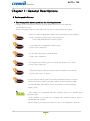
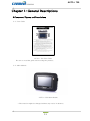
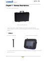
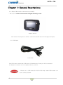
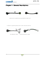
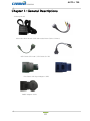
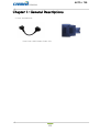
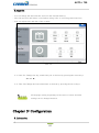
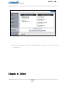
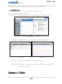
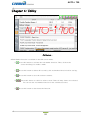
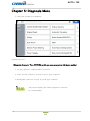
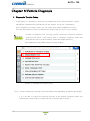
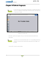
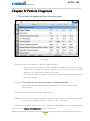
1
AUTO-i 700
User Guide
Ver. 140801A
Safety Cautions
! This information is essential to protect your safety and prevent property damage.
! Make sure to read this thoroughly before using AUTO-i700.
! This information is subject to change or add without notice.
! Please refer to Homepage of Carman International Co., Ltd. for the latest version.
Grade A Equipment (Communication Equipment for business purpose)
Pay attention that this is electromagnetic compatibility equipment for business purpose (Grade A).
It is permitted to use except a house.
CARMAN INTERNATIONAL CO., LTD.
1
AUTO-i 700
Table of Contents
Cautions in Use..........................................................................................4
CHAPTER 1General Descriptions...............................................................5
1. Product Features..........................................................5
2. Product Specifications.......................................................6
3. Rechargeable Battery...................................................7
4. Component List..........................................................8
5. Component Figures and Descriptions..........................................................11
6. Power Supply.......................................................24
CHAPTER 2Menu Configuration............................................................25
1. Before Getting Started........................................................................................25
2. Menu Description........................................................................................26
3. Icons..................................................................................27
CHAPTER 3 Configuration....................................................................29
1. System Display Unit....................................................................................29
2. Maker........................................................................................30
3. Display......................................................................................31
4. Time Set............................................................................................32
5. Information..........................................................................................33
CHAPTER 4Record Data.........................................35
1. Flight Record.....................................................................35
2.TextShot...............................................................................36
3. Screen Capture..............................................................................37
2
AUTO-i 700
Table of Contents
CHAPTER 5Diagnosis Menu...........................................................................39
1. How To Connect Self-Diagnostic Connector and Select
Diagnosis Program.........................................39
CHAPTER 6Vehicle Diagnosis..................................................42
1. Diagnostic Trouble Codes.............................................................................42
2. Erase/reset DTC ...........................................................................45
3. ParameterData.............................................................................46
4. Actuator Test .......................................................................................51
5. Resetting Adaptive Values.............................................................................54
6. EVAP. Leakage Test ..........................................................................55
7. PCM Lock(MEC) Setting........................................................................56
8. Misfire Delay Reason .............................................................................57
9. System Information...........................................................................58
CHAPTER 7OBD-II Diagnosis Menu.................................59
1. OBD-II Overview....................................................................................59
2. How To Connect Self-Diagnostic Connector and Select Diagnosis Program.....60
CHAPTER 8OBD-II Vehicle Diagnosis...............................62
1. Readiness Test ........................................................................62
2. Parameter Data.........................................................................64
3. Diagnostic Trouble Codes...........................................................................66
4. Erase/Reset DTC.........................................................................68
5. Monitoring Test Results..........................................................................69
6. BI-Directional Control...........................................................................72
7. Vehicle Information............................................................................73
CHAPTER 9 Program Download .................................................75
Appendix: Registration.............................................................................76
Q & A.............................................................................77
Certificate of Information and Communication Equipment...................................78
WARRANTY CARD..............................................................................79
3
AUTO-i 700
Cautions in use
Safety Instruction
Cautions in Use
AUTO-i 700 mentioned in this User's Guide is designed for those who have
basic qualifications for using this system.
Users should follow the safety instructions for safe and efficient use of the product.
The cautions of use are as follows:.
- Do not drop AUTO-i 700.
- Always use it in the rubber shroud to product it.
- Do not place AUTO-i 700on the power distributor.
-Although AUTO-i 700 is manufactured to internally prevent the
interference from the electromagnetic waves, the strong interference
by excessive electromagnetic waves may damage the product.
- Excessive surge or electric shock fed by a power cable may damage
the power supply system of AUTO-i 700.
- So, do not use the product while the power supply is unstable.
- The voltage rating of the AC/DC adapter is 12V DC.
- Be sure to use an AC/DC adaptor with the rated voltage.
- Be careful not to let water or oil get into the product.
- The product can be severely damaged.
- Please check if there is short circuit through communication connectors of
OBD-II or a vehicle in the case of flooded cars.
- It can cause damage of scanner.
- Be sure ot use the USB cable supplied by Carman International only.
- Otherwise, your PC or product can be damaged.
- Wireless update or wireless communication requires no hurdle between
scanner and wireless devices. Also, it is recommended to communicate within 10 km.
4
AUTO-i 700
Chapter 1: General Descriptions
1. Product Features
AUTO-i 700 can check vehicle ECU information and malfunction status through the
OBD-II/EOBD and CAN communication.
You can connect AUTO-i 700 to the vehicle diagnostic connector with a diagnosis
cable to check if any of the engine, automatic transmission, ABS, air bag, power steering
and other devices has an error, view current data and use actuator drive features..
AUTO-i 700 has the following features:
▶ Diagnoses Korean, Japanese and European vehicles.
- Support OBD-II/EOBD, MOBD
- Support CAN,SAE-J1850,ISO9141-2/KWP2000,J1587
▶Supports vehicle troubleshooting and current data search.
- You can diagnose vehicles with their sensors and switches, and save and reload
the current data.
▶ Supports automatic actuator inspection.
- This function runs/stops the actuator and switches forcibly in order to check if the
corresponding active device is normal..
▶ You can use saved data and upgrade the diagnosis program by connecting the product
to your PC with wire or wireless.
▶You can change the sound effects and display unit of the AUTO-i 700.
▶Provides the LCD brightness adjustment function.
▶ You can check the latest data and update it automatically.
▶ Support real-time screen printing function by wireless.
▶ Support Log Data function to save / send the data in the case of communication error so
that fast customer support and newest communication is available.
▶ Support remote assistance for usage of product by connecting PC and scanner with USB
connector.
5
AUTO-i 700
Chapter 1: General Descriptions
2. Product Specifications
Item
Specification
Dimension
250mm*180mm*40mm
Weight
1.32kg(2.91lb)
CPU
os
Windows CE 6.0
Diagnosis
Cortex M3 120Mhz
Main
Cortex A8 1Ghz
32GB (Micro SD)
Memory
Display
Operating Temp
Storage Temp
7inch Touch LCD(1024*600)
0~45℃(32~113℉)
-20~70℃(-4~158℉)
Protocol
All Flexibility
- Dual CAN(2.0A,2.0B),Singlewire CAN
- ISO914-2, KWP2000, J1850P, J1587
- K/L-line High Speed Serial, Flashing Code
- Ethernet
Button
Operating Voltage
Power button, All touch button
8V ~ 35V
- Please note that if AUTO-i 700 has been under 0℃(32F), it has to stay in
room temperature over 2 hours surely before using it over 0℃.
-If AUTO-i 700 moves from low temperature to room temperature,
condensations inside the device can be generated and it can cause damage
or malfunction.
- So, please do not place this device in the cold if possible.
6
AUTO-i 700
Chapter 1: General Descriptions
3. Rechargeable Battery
* The rechargeable battery pack has the following features
-Voltage of the rechargeable battery pack gradually decreases even when the
system does not run.
- Before using the product for the first time, be sure to fully charge the battery.
- Always use the rechargeable battery pack provided by Our Company.
- Using a 3rd party product may cause explosion.
(7.4V 2200 mAh lithium ion battery pack)
- Do not heat the rechargeable battery pack.
- It may cause explosion.
- Do not short the battery pack terminal.
- It may cause explosion.
- Do not place the battery pack on or near hot material over 60ºC.
- It may cause explosion.
- Keep the battery pack away from touch of children or an animal.
- It may cause a fire or injury.
- To prevent the battery pack from being discharged, always connect
the power source before using the system. Screen captures, flight
record and other information can be erased due to the discharged
battery pack..
- The battery is consumable and the warranty period is 6 months from
purchase date.
- If the product is not used over 3 months, the contained battery may be
discharged and swollen.
- Please charge your battery at least once per 2 or 3 month for 24 hours.
.
7
AUTO-i 700
Chapter 1: General Descriptions
4. Component List
1. Basic kit
NO
Part No.
Description
1
AY-ELPT-A700
AUTO-i 700 Main Body
2
CB-CYAT-0001
DLC Main Cable (16P 2M)
3
CB-CYVG-0006
Cigarette Lighter Power Cable
4
CB-CNHC-0004
Battery Extension Cable
5
PC-02HC-P009
Power adapter (5A)
6
CB-CYTP-0004
AC/DC Power Cord
7
CB-CYAU-001A
USB Cable(B Type)
8
LA-MCAU-E001
User Guide
9
LA-DQAU-A001
CD
10
PK-BGTT-0005
Carrying Case
11
FE-MUDE-0046
Wi-Fi USB Dongle
8
AUTO-i 700
Chapter 1: General Descriptions
5. Cable Component
1) Korean kit
NO
Part No.
Description
1
CB-CYHC-0018
HYUNDAI,MITSUBISHI CABLE (12P)
2
CB-AYHC-0018
KIA ADAPTOR 20P (BLUE)
3
CB-AYVG-0005
DAEWOO,GM ADAPTOR (12P)
4
CB-AYHC-0019
DAEWOO LPG CABLE
5
CB-AYVG-0006
SSANGYONG ADAPTOR (14P)
6
CB-AYVG-0007
SSANGYONG ADAPTOR (20P)
7
CB-AYVG-0008
SAMSUNG / NISSAN ADAPTOR (14P)
8
CB-CNHC-0010
HYUNDAI KEYLESS CABLE
9
CB-CNHC-0009
KIA KEYLESS CABLE
2) Japanese kit
NO
Part No.
Description
1
CB-AYVG-0001
TOYOTA, LEXUS ADAPTOR (17P"R")
2
CB-AYVG-0002
TOYOTA, LEXUS ADAPTOR (17P"C")
3
CB-AYVG-0009
HONDA ADAPTOR (3P)
4
CB-AYVG-0012
HONDA ADAPTOR (5P)
5
CB-AYVG-0011
SUBARU ADAPTOR (16P-9P)
6
CB-AYVG-0010
MAZDA "C" ADAPTOR (17P)
7
CB-AYVG-0003
MAZDAADAPTOR (6P + 1P)
8
CB-AYVG-0008
NISSAN ADAPTOR (14P)
9
CB-CYHC-0018
MITSUBISHI ADAPTOR (12P)
10
CB-CYVG-0007
MITSUBISHI CABLE (12P+16P)
9
AUTO-i 700
Chapter 1: General Descriptions
3) European kit
NO
Part No.
Description
1
CB-AYHC-0016
Mercedes Benz Board (38P)
2
CB-CYHC-0023
Mercedes Benz Cable (3 liners)
3
CA-PSA1-0002
PSA Cable (2P)
4
CB-CYHC-0022
Audi / VW Cable (2+2P)
5
CN-T005-AM06
Fiat Cable (3P)
6
CB-AYVG-0014
Opel Adapter (10P)
7
CB-AYVG-0013
BMW Adapter (20P)
4) USA/Australian kit
NO
Part No.
Description
1
CB-CYHC-0031
Ford Cable (20P)
2
CB-CYVG-0009
Holden Cable (6P)
10
AUTO-i 700
Chapter 1: General Descriptions
6.Component Figures and Descriptions
6-1. User Guide
AUTO-i 700 User Guide
Be sure to read the guide before using the product..
6-2. Main Module
AUTO-i 700 Main Module
* The exterior might be changed without any notice in advance.
11
AUTO-i 700
Chapter 1: General Descriptions
6-3. Connectors and Key
-Connectors on upper right side -
①
②
- Connectors on upper left side -
③
④
⑤
1. Power connector: It is for a AC/DC power adaptor and a cigar jack.
2. Gas analyzer connector: It is for the gas analyzer that Carman International sells.
(The gas analyzer sells separately.)
3. RJ45: It is not supported just now. (Later it is supposed to support.)
! Please do not insert a LAN cable.
ㅍ
4. DLC connector: It is for DLC communication cable to diagnose vehicles.
5. Hole for a touch pen: It is for keeping touch pen.
- Connectors on left side -
①
②
- Connectors on right side -
③
④
⑤
⑥
1. Forced Termination: This switch can interrupt power emergently if it is overloaded
while using.
2. USB A Type: Connecting to external device.
3. HDMI: Connecting to external monitor. (later, it will be supported by update)
4. USB B TPYE: Connecting to PC for update.
5. USB mini B: USB port for support J2534 communication
(Later, it will be supported on our website.)
6. J2534 power port: power port forJ2534
(Later, it will be supported on our website.)
12
AUTO-i 700
Chapter 1: General Descriptions
6-4. AUTO-i 700 Carrying Case
AUTO-i 700 Carrying Case
AUTO-i 700 includes a number of adaptors and cables for diagnosing vehicles.
When the product is not in use, store it in the supplied carrying case to prevent damage
and loss.
6-5. Touch pen
Picture no.1 Touch Pen
Picture no.2 Hole for Touch Pen
You can prevent the touch pen from loss or damage by keeping it into the hole for touch pen
like the picture no.2.
13
AUTO-i 700
Chapter 1: General Descriptions
6-6. Rubber Shroud (fit to the main body initially)
- The color of rubber shroud can be changed according to user
Rubber Shroud
The rubber shroud protects AUTO-i 700 from external electrical and physical impact.
6-7. USB Cable
USB Cable
The USB cable connects the USB ports of Carmanscan AT and your PC to download
the diagnosis software or save captured files to your PC.
- Please use a USB cable for AUTO-i700 only. Other USB cables can
cause contact problem.
14
AUTO-i 700
Chapter 1: General Descriptions
6-8. CD
*Components of CD
- Installation Driver
- PC Program
- PDF Program
- Basic Diagnostic Data
- User Guide
6-9. Wi-Fi USB Dongle
-Newest diagnostic data can be updated automatically via Wi-Fi(USB A Type). Also,
without wire, captured screens in the scanner can be printed via PC that is connected to
a printer.
(Later, it will be supported through our website.)
15
AUTO-i 700
Chapter 1: General Descriptions
6-10. Cigarette Cable
Cigarette Cable
This cigarette cable connects AUTO-i 700 and a vehicle so that it can supply power.
AUTO-i 700 has internal battery inside so it can boot without other power
but if power of batter is low and it is not charged, you can use cigarette
cable or AC/DC power adapter.
6-11. Battery Extension Cable
Battery Extension Cable
This battery extension cable make AUTO-i 700 to get power from battery of a vehicle
directly by connecting to a cigarette cable.
16
AUTO-i 700
Chapter 1: General Descriptions
6-12. DLC Cable
DLC Cable
The DLC cable is also called the OBD-II cable. All vehicles released recently have built-in
OBD-II connectors compatible to the OBD-II specification.
It is possible to diagnose new model vehicles by directly connecting the DLC cable. It is not
necessary to connect any additional power source as power is feed through the diagnostic
connector.
Old model vehicles should be diagnosed by connecting an additional
adapter.
6-13. AC electrical power cord / adapter
AC electrical power cord / adapter
When you want to download the diagnosis program or search flight record, you can use
this AC/DC electrical power adapter to feed power.
Also, can charge the battery built in the product..
17
AUTO-i 700
Chapter 1: General Descriptions
6-14DLC Adapter
The DLC adapter is used to diagnose vehicles by connecting it to the DLC main connector.
As there are similar shaped adapters, make sure to check the vehicle manufacturer name
on the adapter before use.
Also, there can be various adapters for one manufacturer. Therefore, be sure to check the
shape and pin numbers of the diagnostic connector in the vehicle.
Some vehicles do not supply power through the diagnostic connector.
Do not connect any power supply if power can be supplied through the
diagnostic connector..
1) Korean kit
SAMSUNG / NISSAN ADAPTOR (14P)KIA ADAPTOR 20P (BLUE)
DAEWOO,GM ADAPTOR (12P)
SSANGYONG ADAPTOR (14P)
SSANGYONG ADAPTOR (20P)
18
AUTO-i 700
Chapter 1: General Descriptions
DAEWOO LPG CABLEHYUNDAI,MITSUBISHI CABLE (12P)
2) Cable for registering trans meter codes to Korean vehicles.
KIA KEYLESS CABLE
HYUNDAI KEYLESS CABLE
19
AUTO-i 700
Chapter 1: General Descriptions
3) Japanese kit
TOYOTA, LEXUS ADAPTOR (17P"R")TOYOTA, LEXUS ADAPTOR (17P"C")
HONDA ADAPTOR (3P)HONDA ADAPTOR (5P)
SUBARU ADAPTOR (16P-9P)MAZDA "C" ADAPTOR (17P)
MAZDA ADAPTOR (6P + 1P)NISSAN ADAPTOR (14P)
20
AUTO-i 700
Chapter 1: General Descriptions
MITSUBISHI ADAPTOR (12P)
MITSUBISHI CABLE (12P+16P)
21
AUTO-i 700
Chapter 1: General Descriptions
4) European kit
Mercedes Benz Board (38P) Mercedes Benz Cable (3 liners)
PSA Cable (2P) Audi / VW Cable (2+2P)
Fiat Cable (3P) Opel Adapter (10P)
BMW Adapter (20P)
22
AUTO-i 700
Chapter 1: General Descriptions
5) Usa/ Australian kit
Ford Cable (20P) Holden Cable (6P)
23
AUTO-i 700
Chapter 1: General Descriptions
7. Power Supply
1. Cigarette Lighter Power Cable
Power is fed through the cigarette lighter power cable.
However, when the vehicle ignition switch is in the “OFF” position or upon starting
a vehicle, power is not supplied to the cigarette lighter socket.
2. Vehicle Battery
Connect the red clip of the battery extension cable to the (+) battery terminal, and
black clip to the (-) terminal. Connect the cigarette lighter power cable between the
battery extension cable and the product.
In this case, power is supplied anytime regardless of the ignition switch status or
vehicle starting. (Be careful no to discharge the battery.)
Be careful when connecting the cable, as incorrect polarity may
damage the main module..
3. DLC Cable
Where the vehicle satisfies the OBD-II communication convention and uses a
certain manufacturer's diagnostic connector, the DLC main cable can supply power
to the product directly without a separate power supply.
4. Rechargeable Battery Pack
If the built-in battery is used, you can use the system for 3 to 4 hours without any
separate power supply..
The available time may change based on use and environment.
How to charge: When the product is not in use, connect it to the power
source by the AC/DC power adapter that came with the product to charge
the built-in battery. (12h ~ 24h)
5. AC/DC Power Adapter
If the AC/DC adaptor is used for power supply, the battery will be automatically
recharged depending on programs and it is also used for power supply to the main
module..
24
AUTO-i 700
Chapter 2: Menu Configuration
1. Before Getting Started
1-1.
Before using the system, check whether or not the battery is fully charged. If it
is notcharged, then connect external power supply or recharge the battery
before using thesystem.
- If you use the system by connecting it to a vehicle, you can also feed power
to it through the vehicle diagnostic connector.
If power is not feed by the vehicle diagnostic connector, you need to
connect the cigarette lighter power cable to feed power before you
start communication with the vehicle. Voltage mismatch between the
ECU and AUTO-i 700 may cause a communication error.
1-2.Before using the system, make sure to download the diagnosis program.
The diagnosis program will be stored in the system memory.
- Before using the system, check if the diagnosis program matches the
option youhave purchased.
- Basically, a diagnostic program is installed before delivery.
Also, you can get the latest diagnostic data from our website or from where
you purchase.
25
AUTO-i 700
Chapter 2: Menu Configuration
2. Menu Description
When turning ON AUTO-i 700, the main screen with the menu is displayed as follow:
-Main Screen 01. OBD II//EOBD
- This menu is to diagnose and test some parts that are related with exhaust gas only if user`s
vehicle has OBD II/EOBD
02. Car, Commercial, Bike
- This menu provides scanner's own functionality such as vehicle diagnosis, service data search,
actuator activation, etc.
- Depending on your option, you can perform diagnosis on Korean, Japanese, European,
Australian and USA vehicles.
03. Download
- In this menu, AUTO-i700 can connect to PC so that it can upgrade software and download saved
files etc. in AUTO-i 700 to PC.
04. Config.
- In this menu, you can check the system display unit, favorite maker setting, screen setting, time
setting and system information
05. Utility
- In this menu, you can check flight record, saved list, captured screen etc.
06. Repair
(Later, it will be supported on our website.)
26
AUTO-i 700
Chapter 2: Menu Configuration
3. Icons on Main Screen
3-1 Icons on main screen
①
②
③
1. Clock
- This displays the current time.
2. Sound
- It can sound on/off by touch.
3. Battery Status
- Charging status: This indicates external DC power is being supplied and
your battery is being charged at the same time.
-Battery status: It shows power remaining on your battery.
After charging the battery, use AUTO-i700 in order to avoid discharging.
27
AUTO-i 700
Chapter 2: Menu Configuration
3-2 Icons on the CAR menu
① ②
③
④
-Setting-
1. Setting: Press this button to turn on/off 'Show DLC Message Box' and 'Log on'
functions. If you select one button, the button is brighten and activated.
2. Capture: Press this button to capture a screen and save it.
3. Home: Press this button to return to the main screen.
4. Back: Pressing this button to return to the previous screen.
5. Autoselect Car Menu (Press this button to Activate. then the color of icon changes to white.)
- Activate Autoselect Car Menu and AUTO-i 700 starts from the Menu screen
directly.
- That is, the Main screen is skipped.
6. Show DLC Message Box (Activation makes the color of icon white.)
- Activate this button to show how to connect when select connectors.(Page39)
- On the other hand, if you do not activate this function, you can skip a step of how
to connect.
Chapter 3: Configuration
28
AUTO-i 700
1. System Display Unit
- In this menu, you can change the display unit of data which are sent from a vehicle.
- The units of various information, such as speed, temperature, pressure, angle,air flow
and sound, can be checked and modified.
- System Display Unit-
1-1.
It is possible to change the display units all at once according to the region that
uses“Metric” or “Yard-Pound” system.
1-2.
After changing the display unit, click the Save button to save your modification.
- SPEED : You can change between Km/h and MPH.
- TEMPERATURE : You can change between ℃ and ℉.
- PRESSURE : You can change among mbar, kPa, inHg and psi.
- ANGLE : You can change between ° and %.
- AIR FLOW : You can change between gm/s and lb/m.
- SOUND : It can be turned ON or OFF.
Chapter 3: Configuration
29
AUTO-i 700
2. Maker
- It is possible to select your favorite vehicle maker to be displayed on top in the
diagnosismenu..
- This function can save time to search for the desired vehicle maker whenever
the diagnosis is made.
- Maker-
2-1. Maker - Please select a maker and click the save button. then please click the
confirm button.
2-2. Initialization of favorite: It initializes the saved favorites.
- Please click the initialize favorite button and confirm to save changed settings.
The list of makers shows some models that is not included in what you
download.
You can check valid model in the menu of the car or the commercial car on
main screen.
Chapter 3: Configuration
30
AUTO-i 700
3. Dispaly
- You can set up language and brightness of LCD.
- Setting brightness will improve efficiency of work in a dark or bright place.
Also, language can be selected according to a user.
-Dispaly-
3-1 OS Language - The language of the operating system and diagnostic program can
be set among the languages that are stored in the internal memory.
3-2 Brightness- Press the “-” and “+” buttons to adjust the screen brightness.
- Please note that if you set up the brightness to the max, the battery will be dead earlier.
Chapter 3: Configuration
31
AUTO-i 700
4.Time Set
- You can change the date and time stored in the internal memory.
- The time stored in this menu is used when saving a file or executing other functions.
- User can adjust time and date of the scanner.
-Time Set-
4-1. Date Set: Change the day, month and year as desired by pressing the arrow keys
(▲ and ▼).
4-2. Time Set:Change the hour and minute as desired by pressing the arrow keys.
OS language setting, depending on the state set a date and time
settings can be changed notation.
Chapter 3: Configuration
5. Information
32
AUTO-i 700
You can input your information or check system information.
-Information-
5-1. User information is shown and you can edit and save information.
5-2. In order to change the information.please select a item to edit, click the edit button on below
bar and input information.
5-3. Other languages except English can be input using download program of PC.
Chapter 3: Configuration
33
AUTO-i 700
-Information-
5-4. Press the Information button. Then, the information is shown so you can check system
and program.
Chapter 4: Utility
34
AUTO-i 700
This function is to check flight records, text shots and screen captures etc.
1. Flight Record
- You can save service data of a vehicle to analyze it. (Refer to P49)
- You can save the desired service data.
- This function is useful when data should be saved to diagnose an intermittent symptom.
- Flight Record–
1-1. Data View: Click this button to display the data only selected by the user.
-Text View-
-Graph View-
1-2. Delete: Click this button to delete the file selected by the user.
1-3. Rename: Click this button to rename the file that was temporarily set when saving
the file (only in English).
Chapter 4: Utility
35
AUTO-i 700
2. Text Shot
- You can save a measured value you select among system error code and sensor data by
choosing specific time during diagnosis. and you can use the values of specific time to
analyzation.
- You can save all data at once. So, you can check whole car conveniently.
-Text Shot-
2-1. Full Screen: It shows recorded data of selected item in full screen.
2-2.Delete: It delete a selected item.
2-3. Change filename: User can change a file name.
Chapter 4: Utility
36
AUTO-i 700
3. Screen Capture
- Press the
button on the left upper side if you need to capture screens while using.
- Conveniently, screens are saved.
- Screen Capture-
3-1.Full Screen: Press this button to show the saved files on a full screen.
Red marker function is available in the full screen mode. the Red Pen function makes
a user take a note on the screen and edit it freely.
3-2.Slide Show: Select several files and press this button to display them in a
slideshow.
3-3.Rename: Press this button to rename the file.
3-4.Delete: Press this button to delete a file.
3-5.Initialization : Press this button to initialize by deleting all saved files.
3-6. Save: Press this button to save changed items.
- Unnecessary buttons may not be saved in some items.
37
AUTO-i 700
Chapter 4: Utility
-Full Screen -
# Red Marker function is available in the full screen mode.
①
:Press this button to activate the red marker function. Then, click on the
screen and drag it to make a mark.
②
:Press this button to delete all records by the red marker function before saving.
③
:Press this button to save the written contents.
④
:Press this button to switch to other screen if data of many items are selected.
You can use the red marker function on the switched screens.
⑤
:Press this button to deactivate the function.
38
AUTO-i 700
Chapter 5:Diagnosis Menu
1. How To Connect Diagnostic Connector and Select Diagnosis Program
(It is common to Korean, Janpanese, European and USA vehicles)
1. Locate the diagnostic connector in the vehicle.
- Most vehicles released after year 2002 conform to the OBD-II Protocol and
have OBD-II diagnostic connectors.
- Most OBD-II vehicles have their diagnostic connectors on the section over the
brake pedal under the steering wheel.
- If an additional adaptor is required, the scanner display shows the type of the
necessary adaptor and the location of the diagnostic connector.
-Location of OBD-II diagnostic connector-
2. Use the DLC main cable to connect the vehicle's diagnostic connector and AUTO-i 700.
3. Turn on AUTO-i 700
-If power is not feed through the diagnostic connector and the AUTO-i 700
battery is not fully charged, you need to connect an additional power supply
(vehicle battery or cigarette lighter power cable, etc).
4. Select a kind of vehicle.
39
AUTO-i 700
Chapter 5:Diagnosis Menu
5. Select the maker of the vehicle to diagnose.
-Vehicle Maker Selection -
6. Select a vehicle on diagnosis menu.
- Vehicle Model selection -
40
AUTO-i 700
Chapter 5: Diagnosis Menu
7. Select the system to be diagnose.
-System Selection-
*Diagnostic Connector Type (TOYOTA models use same connectors with Lexus models.)
1. 16-pin connector: common OBD-II connector
2. Semi-circular connector: Toyota 17-pin C-type connector
3.Rectangular connector: Toyota 17-pin R-type connector
- The screen displays the vehicle diagnostic connector
by a vehiclemaker.
41
AUTO-i 700
Chapter 6:Vehicle Diagnosis
1. Diagnostic Trouble Codes
- In this menu, it is possible to check for any malfunction of the selected vehicle system
through the communication with the ECU in the vehicle. As AUTO-i 700displays
DTCs (Diagnostic Trouble Codes), you can easily check where malfunction occurs.
Also, the description for DTCs is displayed as well to help you service your vehicle.
In order to diagnose DTC correctly, please check the connection between
connector and AUTO-i 700. Please refer to Chapter5: Diagnosis menu and
check details such as Vehicle maker, model and displacement etc.
The helpfunction may differ between vehicle makers
Picture 1-1 Diagnostic Trouble Codes
Note - Items of Diagnostic Trouble Codes may differ from depending on makers and models.
1. If a car and a system are selected correctly in the Vehicle Diagnosis menu and
communication with vehicle is stable, the above picture will be shown.
42
AUTO-i 700
Chapter 6:Vehicle Diagnosis
If it does not show a menu like page 42 and shows "Communication Error"
or does not communicate stably, please check first status of the target car
or connection of cables.
-Diagnostic Trouble Code-
2. The DTC search screen appears. Now, you can check current and old DTCs and
erase them.
- Old DTCs are not activated unless there is no corresponding fault history.
-Diagnostic Trouble Codes, detected only when the list save applies, can
be saved.
3. Press DTC to check current troubles.
43
AUTO-i 700
Chapter 6:Vehicle Diagnosis
- DTC -
3-1. DTC - Press this button to check current DTCs.
- In the case of MIL type vehicle, you can check codes through the DTC list.
3-2. History DTC - Press this button to check old DTCs.
3-3. Erase DTC - Press this button to clear DTCs.
3-4. Freeze Frame - Press this button to check data at that moment of malfunction.
3-5. Detail - Press this button to display detailed information for DTCs.
3-6. Recheck - Press this button to check for DTCs again.
- The module checks the ECU information again for DTCs.
- Press [DTC] and [History DTC] buttons again.
44
AUTO-i 700
Chapter 6:Vehicle Diagnosis
2. Erase/Reset DTC
1.
If you select a car and a system correctly on the menu and if communication with a car
works successfully, it shows the DIAG MENU like a picture below.
Press the ERASE/RESET DTC button.
-ERASE/RESET DTC-
2.
You can see "Yes" & "No" buttons. If you choose the YES button, the DTC is deleted. If
you choose the No button, it returns to previous step.
There are current and old DTCs.When trying to clear old DTCs, they
are cleared immediately and they are not set again. However, when trying to
clear current DTCs, they are cleared for a short period of time but they are
activated again.In this case, clear DTCs again after checking and repairing
malfunction parts for the corresponding DTCs
45
AUTO-i 700
Chapter 6:Vehicle Diagnosis
3.Parameter Data
- In the PARAMETER DATA menu, the module can communicate with the vehicle ECU
to check data and control values of each sensor of the selected system and to check
conditions of various switches and actuators.
It is important to select the vehicle specifications correctly for accurate
sensor data measurement. Make sure to set the vehicle displacement,
manufactured year, fuel, etc. correctly.The live data list can differ even with
the same vehicle models
-Parameter Data Selection -
NOTE) The menu for Parameter data selection, shown in the above picture, can differ by
vehicle makers and models.
1. When selecting the correct vehicle model and system from the menu and communication
with the vehicle is properly established, the menu appears as the picture above.
Select Parameter DATA and press the ENTER key
If the message indicating a communication error is displayed instead
of the menu like the figure above or communication cannot be established,
check the vehicle condition and the connection status of the diagnostic connector again.
46
AUTO-i 700
Chapter 6:Vehicle Diagnosis
2. The Live data list is displayed as shown in the below picture.
-Live Data--
Graph mode: Press this button to check live data in graphs..
- Press this button to check live data in graphs.It is helpful to convert the current
vehicle data to graphs for tendency analysis. (Up to 30 items can be selected
while up to 8 graphs can be displayed at a time.)
- To convert live data to graphs, such data are need to be fixed. Then, only these
fixed data change.
File mode: Press this button to save sensor data or check the saved files.
-Data are stored in the internal memory and they can be stored synchronized
with your PC.
Dual DTC: Press this button to display DTCs at once.
Guide Info: If the selected system has help information, this button is activated. Then, press
this button to display information. (Later, it will be supported.)
Change Unit: Press this button to move to configuration and change system Unit and time etc.
Please refer to Chapter 3 Configuration for more information.
47
AUTO-i 700
Chapter 6:Vehicle Diagnosis
If you use the fix function, values are changed only for the fixed items so
you can measure changed values faster and can diagnose more precisely.
- Graph Mode:This function is to check live data in graph forms for tendency
analysis.
-Graph Mode-
- Text Mode: Press this button to switch to the text mode..
- File Mode: Press this button to save data and check saved files.
- Dual DTC: Press this button to check DTC and sensor data at the same time.
-Auto: Press this button to reset graph based on the maximum and minimum values
from ECU.
- up(△),down(▽): In the graph view mode, up to 8 live data can be displayed at a time.
If the number of sensor data displayed on the screen at a time is set to less than 8,
the remaining live data are displayed in the list on the bottom.
- Reset: Press this button to initiate the Graph View.
48
AUTO-i 700
Chapter 6:Vehicle Diagnosis
-File Mode: Press this button to save data or check the saved data.
Flight Record Start: : Press this button to start to record the selected live data.
-The data can be recorded for up to 1 hour and the recording time can vary depending on
the number of the selected live data.
(When the recording operation is performed for 1 hour, it stops automatically.)
Only selected Flight record data by user is saved.
On the other hand, if a user select some list, only the selected list is saved
but if a user select nothing, all list is saved.
Record Data Viewer: Press this button to check or search for the stored file
- The screen displays the Record Data menu pane where you can check the saved data
through the flight record list.
- For the flight record, text shot, screen capture and gas analyzer functions, refer to
Chapter 4. Record Data.
49
AUTO-i 700
Chapter 6:Vehicle Diagnosis
- Dual DTC: The upper half of the screen displays the live data while the lower half of the
screen displays the DTC list.
if there is any DTC, the corresponding sensor data can be checked for comparison.
- Dual DTC -
- Press the DTC list button to exit the dual display mode and return to the
Record Data Viewer.
In the Dual DTC mode, Press the Text shot button to save DTC and
sensor data.
50
AUTO-i 700
Chapter 6:Vehicle Diagnosis
4. ACTUATOR TEST
- In this menu, you can start and stop actuators and switches forcibly to diagnose them.
- The actuation function is available depending on vehicle makers and models.
- Actuator Test-
1. If a car and a system are selected correctly in the Vehicle Diagnosis menu
and communication with vehicle is stable, the above picture will be shown
Select a Actuator Test.
If above picture is not shown, the communication error appears or
communication does not work, check again the status of vehicle and
connection of cables for diagnosis.
51
AUTO-i 700
Chapter 6:Vehicle Diagnosis
2. The screen as below appears.
-Actuator-
3. Press the start button after selecting a item.
- Figure 3-1 Actuator Start & Stop -
52
AUTO-i 700
Chapter 6:Vehicle Diagnosis
- Before starting actuation, make sure to check the operating condition to inspect
the system in the proper condition.
- The actuator time differs by the actuated items.
4. Press the Stop button to stop the actuator function.
- Press this button to stop the actuator function during diagnosis.
- Press the arrow button on the right top corner of the screen to stop
the actuator function too.
- Actuator graph mode -
5. In the figure 3-1, Press Show sensor button to see sensor data. After selecting a
sensor data, Press the graph mode button to change data value to a graph.
The actuation result is judged by noise from the running actuator or
switch and vehicle RPM change.
Therefore, it is recommended to perform the actuation test in a quiet
area and use current data values as a reference.
If target system does not support sensor, actuator and dual display, it
supports items of actuator without items of sensor.
53
AUTO-i 700
Chapter 6:Vehicle Diagnosis
5. Resetting Adaptive Values.
- The resetting adaptive values initiates ECU by clearing values of sets in ECU.
- The clearing learning values may be different depend on car makers and models.
54
AUTO-i 700
Chapter 6:Vehicle Diagnosis
6. Evap. Leakage Test
- Press this button to check if there is leakage from a oil tank .
55
AUTO-i 700
Chapter 6:Vehicle Diagnosis
7. PCM Lock(MEC) Setting
- This function is to prevent data or programs from adjustment.
- System information differs from depend on car makers and models.
56
AUTO-i 700
Chapter 6: Vehicle Diagnosis
8. Misfire Delay Reason
- This function is to check the number of misfire in each cylinders.
- System information differs from depend on car makers and models.
57
AUTO-i 700
Chapter 6:Vehicle Diagnosis
9.System Information
-System Information shows information related with system such as system model and
software version etc.
- System information differs from depend on car makers and models.
58
AUTO-i 700
Chapter 7: OBD-II/EOBDDiagnosis Menu
1. OBD-II/EOBDOverview
■ Purpose ofOBD-II/EOBD
- OBD-II/EOBDis intended to find what caused the emission to increase, diagnose the
part of thecause and light the warning lamp in order to provide faster and more
precise repair..
■ OBD-II/EOBDRegulations
- If emission increases due to defected parts, diagnose components and cause, and turn
on the Malfunction Indicator Lamp (MIL).
- Trouble information shall be read by the standard diagnosis tools (GST).
■ OBD-II/EOBDRegulations《 Major Check List 》
The warning light shall be on before the emission reaches 1.5 times of the permissible
limitdue to any of the following troubles or performance degradation.
- Catalyst purification rate (this diagnosis is for HC emission only. This is being phased in
for 1.75 times of HC limit from TLEV), misfire, EGR System, O2 sensor and fuel system
secondary air system
- Diagnose all sensors and actuators used for controlling the engine to see if they function
properly as well as wirings for an open/short circuit.
- Diagnose the entire evaporation system to see if it leaks.
- Perform diagnosis when the PCV valve and the crankcase or the PCV valve and the
intake manifold are disconnected.
- Diagnose the thermostat when the coolant temperature fails to reach the specified
temperature where the diagnosis can be made to other items in a given time after
starting the engine.
59
AUTO-i 700
Chapter 7: OBD-II/EOBDDiagnosis Menu
2. How To Connect Diagnostic Connector and Select Diagnosis Program
(It is common to Korean, Japanese, European and USA vehicles)
1. Locate the diagnostic connector in the vehicle.
-Most OBD-II vehicles have their diagnostic connectors on the section over
the brake pedal under the steering wheel. (OBD-II Diagnosticconnector location)
- Since vehicles without the OBD-II diagnostic connector do not conform tothe
OBD-II/EOBD communication protocol, you can not use the OBD-II/EOBD vehicle
diagnosis function to them.
-OBD-II Diagnosticconnector location 2. Use the diagnosis cable to connect the vehicle's diagnostic connector and
AUTO-i 700
3. Turn onAUTO-i 700.
- As OBD-II vehicles feed power through the diagnostic connector to the
module, they do not need any additional power supply..
4. Press the OBD-II/EOBD button on main screen of AUTO-i 700 to see diagnosis items.
5. Diagnosis function includes Auto-searching, ISO9141-2/KWP2000, J1850PWM/J
1850VPW, CAN communication(Figure 5-1) etc. please refer to Chapter 8 OBD-II
Vehicle Diagnosis for more information.
Whenever performing diagnosis, make sure that the ignition
switch is in the "ON" position. If the ignition switch is placed in the "OFF"
position, power cannot be feed to the ECU and the diagnosis with AUTO-i 700
cannot be performed.
60
AUTO-i 700
Chapter 7: OBD-II/EOBDDiagnosis Menu
5-1) Communication screen
- Communication-
5-2) Connect a OBD2 16pin connector. (DLC main cable)
- Connect OBD2 16pin connector -
61
AUTO-i 700
Chapter 8: OBD-II/EOBDVehicle Diagnosis
1. READINESS TEST
-The readiness test tries making communication with your vehicle to review general
items of ECU modules that response.
-Readiness Test Selection-
1-1.
If communication with the vehicle is established successfully, the menu above
appears. Select READINESS TEST.
If no menu like above is displayed or communication cannot be
established, check the vehicle condition and the connections status of
the diagnostic connector again.
In addition, check if your vehicle supports OBD-II communication.
62
AUTO-i 700
Chapter 8: OBD-II/EOBDVehicle Diagnosis
-Readiness Test-
*Results
1. NOT CMPLTD: The test has not been completed.
- This appears when the test was not completed owing to the abnormal
ECU or sensorrequired to display the test result..
2. COMPLETED: The test has been completed.
3. NON APPLIC: The item is not applied to the tested vehicle.
63
AUTO-i 700
Chapter 8: OBD-II/EOBDVehicle Diagnosis
2. PARAMETER DATA
-You can check the PARAMETER DATA specified by the OBD-II/EOBD standard in this menu.
-PARAMETER DATA Selection -
2-1. If communication with the vehicle is established successfully, the above menu
appears. Select the PARAMETER DATA.
If no menu like above picture is diplayed or communication cannot be
established, check the vehicle condition and the connection status of the
diagnostic connector again.
In addition, check if your vehicle supports OBD-II communication.
64
AUTO-i 700
Chapter 8: OBD-II/EOBDVehicle Diagnosis
-OBD-II/EOBD LIVE DATA-
2-2 Sensor data are listed on the screen as shown in above figure. you can check
values of each sensor.
.
-Refer to the description from "Chapter6 vehicle diagnosis for each
button`s function.
- Live data items in OBD-II communication may be different from live
data items that are checked by selecting cars because live data itemsin OBD-II standard are
provided.
65
AUTO-i 700
Chapter 8: OBD-II/EOBD Vehicle Diagnosis
3. Diagnostic Trouble Codes
-Press this button to check trouble code of current vehicle.
-DTC selection3-1. Communication withe vehicle is properly establlished, the above menu appears.
Select Diagnostic Trouble Codes.
If the above menu is not appeared and Communication cannot be
established, check the vehicle condition and the connection status of the
diagnostic connector again. Also, check if your vehicle supports OBD-II
communication.
66
AUTO-i 700
Chapter 8: OBD-II/EOBDVehicle Diagnosis
-DTC-
2-2. DTCs are listed on the screen as shown in above figure. You can check values of
each sensor.
- Refer to the description of "Chapter6 Vehicle Diagnosis" for each
button`s function.
- Live data items in OBD-II communication may be different from live
data items that are checked by selecting cars because live data
items in OBD-II standard are provided.
67
AUTO-i 700
Chapter 8: OBD-II/EOBDVehicle Diagnosis
4. Erase/Reset DTC
1. Select a car model and system in the diagnosis menu. Then, if communication with the
vehicle is established successfully, the menu shown in Figure of Page65 appears.
Select the ERASE/RESET DTC button.
-Erase/Reset
DTC-
2. If the YES & NO window are shown, Select the YES button to clear DTC or select the
NO button to return back to previous step.
There are current and old DTCs. When trying to clear old DTCs, they are cleared
immediately and they are not set again. However, when trying to clear current
DTCs, they are cleared for a short period of time but they are activated again. In
this case, clear DTCs again after checking and repairing malfunction parts for the
corresponding DTCs.
68
AUTO-i 700
Chapter 8: OBD-II/EOBDVehicle Diagnosis
5. Monitoring Test Results
- This menu displays the monitoring test results while the vehicle is being normally
operated.
- To test systems and units of different manufacturers, it is required to specify test
IDs and component IDs.
If there is no test item supported by the vehicle manufacturer, an error message will be
displayed.
-Monitoring
Test Results-
5-1. If communication wih the vehicle is established successfully, the menu above appears.
Select MONITORING TEST RESULTS.
If no menu like picture above is displayed or communication cannot be
established, check the vehicle condition and the connection status of the
diagnostic connector again.
In addition, check if your vehicle supports OBD-II communication.
69
AUTO-i 700
Chapter 8: OBD-II/EOBDVehicle Diagnosis
70
AUTO-i 700
Chapter 8: OBD-II/EOBDVehicle Diagnosis
71
AUTO-i 700
Chapter 8: OBD-II/EOBDVehicle Diagnosis
6. BI-Directional Control
- You can control and test functions related with OBD-II system.
- BI-Directional Control -
6-1.If communication wih the vehicle is established successfully, the menu above appears.
Select BI-DIRECTIONAL CONTROL.
If no menu like picture above is displayed or communication cannot be
established, check the vehicle condition and the connection status of the
diagnostic connector again.
In addition, check if your vehicle supports OBD-II communication.
72
AUTO-i 700
Chapter 8: OBD-II/EOBDVehicle Diagnosis
7.
VEHICLE INFORMATION
- This menu displays information of the ECU installed in your vehicle.
- You can check only the ECU that provides its module information.
- This menu displays information of the ECU installed in your vehicle.
- You can check only the ECU that provides its module information.
-VEHICLE INFORMATION Selection-
7-1. If communication wih the vehicle is established successfully, the menu above
appears. Select Vehicle Information.
If no menu like picture above is displayed or communication cannot be
established, check the vehicle condition and the connection status of the
diagnostic connector again.
In addition, check if your vehicle supports OBD-II communication.
73
AUTO-i 700
Chapter 8: OBD-II/EOBDVehicle Diagnosis
- This menu displays information of the ECU installed in your vehicle like the picture above.
- Press the ENTER button to check system information in detail.
74
AUTO-i 700
Chapter 9: Program Download
It is necessary to download the vehicle diagnosis program to your product in order to use it. if
here is any update due to a new model, system or development, the program should be updated to
the latest one. Also, the latest firmware and PIC data are provided for update to ensure the best
performance of your product. For this update, the dedicated program is needed. The following
describes how to install the program.
1. How to Install download program.
- Use only the USB supplied by our company to connect the PC and AUTO-I 700.
- Select the DOWNLOAD button in main screen of AUTO-i 700.
- Download new software after check how to download it in our website.
Website: http://www.carmanit.com
- In the future, you may download a software automatically via Wi-Fi without connection of
cable. Soon we will make a notice in our website after completing development.
- Please contact to where you purchased about downloading latest software.
75
AUTO-i 700
Appendix: Registration
# We explain how to register using windows 7.
How to register?
# You can register on website or where you purchase our products.
# Website address for registration: http://www.carmanit.com
How to register through website
1. Input http://www.carmanit.com into theaddress bar on browsers.
2. Refer to the JOIN page in our website.
76
AUTO-i 700
Q&A
Q) Communication cannot be established.
A) 1. Check the connection of the diagnostic cable.
- Communication cannot be established if the diagnostic cable is not perperly
connected.
- Some old vehicles may have a problem on pin of DLC.
2. Check if power is properly supplied to the main module.
- Vehicle diagnosis can be affected by unstable power source.
- You need to check power from battery or from DLC connector.
- If the vehicle diagnostic cables cannot supply power from vehicle, connect the
cigarette lighter power cable for power.
- If there is electric potential difference between AUTO-i 700 batteries and
vehicle batteries, communication is not available.
* If the problem is not solved, a hardware of scanner or a vehicle may be out of order.
* If so, the scanner requires to be repaired
* Flooded cars may be not communicated also it will cause damage to your scanner.
So, Check if there is any short circuit in advance before scanning the flooded cars.
Q) I cannot turn on the module.
A)
1. Check if the battery in the module is charged.
- The built-in battery may not be charged.
2. The battery may not be able to function due to the ambient temperature.
- Avoid excessively hot or cold areas.
3. If battery life is over, booting by battery is not available.
* If DLC cable, cigarette cable or AC/DC adapter cannot supply power and
booting is not available, it is required to be repaired.
Q) The touch screen does not function properly.
A) 1. The touch screen coordinates may not be correctly aligned.
- It is possible to test the touch screen coordinates by selecting the
CONFIGURATION from the main menu and then selecting DISPLAY and Test
Touch Coordinate menus in order. If the coordinates are not correct, correct
them using the Calibrate Touch Screen function.
* If the problem is not solved, a hardware of scanner or a vehicle may be out of
order.
* If so, the scanner requires to be repaired.
77
AUTO-i 700
Certificate of Information and
Communication Equipment
[Certification Label for Information and Communication Equipment]
Manufacturer: Carman International Co., Ltd.
Equipment: Vehicle diagnosis device
Model: AUTO-i 700
Manufacturer ID: MSIP-REM-CMi-AUTO-i700
Certificate Date: Aug. 2014
COPYRIGHT ⓒby Carman International Co., Ltd.
All right reserved. No part of this publication may be reproduced, stored in a retrieval system,
or in any form, or by any means, electronic, mechanical, photocopying, recording or
otherwise, without the prior written permission of the author.
78
AUTO-i 700
WARRANTY CARD
Warranty Policy
1. The manufacturer warrants this product to be defect free in material and workmanship for a period of one (1) year
from the date of purchase. Defective products may be returned by the original purchaser within the warranty period,
postage pre-paid together with proof of purchase date to Carman International Co. LTD. Defective products will be
repaired at manufacturer’s discretion, replaced at no charge.
2. The warranty does not apply to any units that have been tampered with, or to damages incurred through improper
use and care, defects caused by abuse or through the usage for purposes other than the intended use, used in a
manner inconsistent with the instructions regarding use, and faulty packing or mishandling by any common carrier.
3. Repairs not covered by this warranty will be performed at the current cost for parts and labor. In no event will Carman
International Co. Ltd’s liability exceed the price paid for the product from direct, indirect, special, incidental or,
consequential damages resulting from the use of this product, its accompanying software, or its documentation
without obligation to notify any individual or entity. Warranties hereunder extend only to customers and are not
transferable.
Warranty Period & Software update
1.Free Software update for Carman International products is fifteen (15) months from date of purchase. After fifteen (15)
months from purchase date, software updates will be optional and will require separate payment per request.
Repair Service
1. If you suspect that you have a problem with this product, please read the operation manual (guide) carefully to ensure
that you are operating this product properly.
2. If you conclude that a real problem exists, check your product according to the procedures on the “Trouble Shooting
Card” and mark your trial records in the blank.
3. Please return the main body or the troubled parts along with the “Trouble Shooting Card” to the repair service center
listed below. Be sure to return them in freight prepaid as we don’t accept freight collect.
Carman International Co., Ltd.
#1210, 12th Floor, Hoseo Univ. Venture Tower, 70, Gasan digital 1-ro, Geumcheon-gu, Seoul,
153-711, Korea
Tel: +82-2-2627-4530~3 Fax: +82-2-852-4951
Email: [email protected]
Homepage: http://www.carmanit.com
79