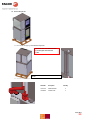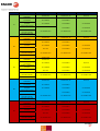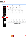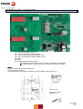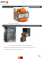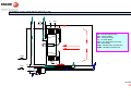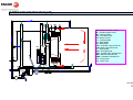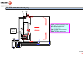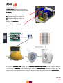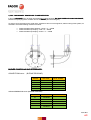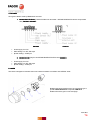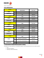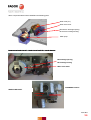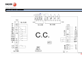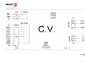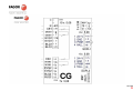
1
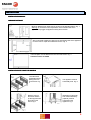
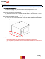
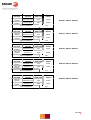
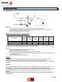
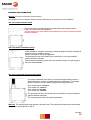
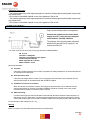
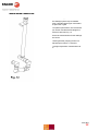
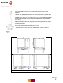
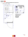
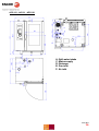
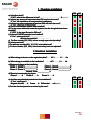
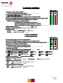
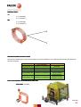
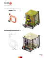
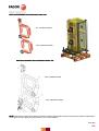
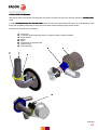
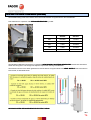
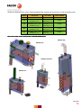
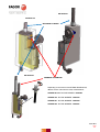
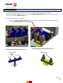
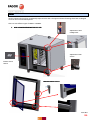
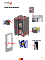
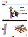
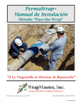
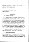
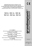
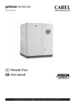
TECHNICAL MANUAL OVENS
“ADVANCE CONCEPT”
“ADVANCE”
“ADVANCE PLUS”
16/11/2012
1
GENERAL SAFETY INSTRUCTIONS
GENERAL INFORMATION
Before switching on the newly installed appliance for the first time, the inside should be cleaned with a cloth soaked
in soapy water. Then switch on the empty oven in Steam mode for ½ hour to eliminate the odours associated with a new
appliance.
Before starting the appliance, check that the cut-off tap for the water supply is open, the cut-off tap for the gas is
open (only in gas models) and that the electricity supply is on.
When the oven is to remain unused for long periods of time, we recommend you close the cut-off tap to the water
supply, the cut-off tap to the gas supply (only gas models), and disconnect the electricity supply.
The oven should always be installed below a extractor hood.
Fagor Industrial recommends you read the safety instructions and the installation and user manual carefully.
Fagor Industrial recommends that the manuals and documents provided with the oven are kept to hand at all times.
The oven should only be used for cooking food in the catering sector. The use of the oven for any purpose other
than the above is considered to be inappropriate and therefore dangerous.
The oven should only be operated with your hands. Any damage due to the use of sharp objects will not be covered
under guarantee.
The oven should be used by trained and qualified personnel.
Other heat sources such as fryers or fry-tops should not be installed close to the oven.
WARNING
The installation, incorrect adjustment, inappropriate maintenance or use of the appliance may cause
material damages and injuries. Before commissioning the appliance, carefully read the instructions.
SAFETY
Do not store or use gases or explosive liquids near the appliance, or introduce liquids containing alcohol
inside the oven.
When the oven is hot, do not open the door suddenly (danger of burns due to hot steam). Do not put cold
water in the chamber when it is hot.
Repairs or adjustments carried out by personnel not belonging to FAGOR INDUSTRIAL
SAT (Technical Assistance Service) or an authorised SAT will imply the cancellation of the
oven warranty.
16/11/2012
2
READING ADVANCE OVEN NOMENCLATURE
“ADVANCE CONCEPT”
A
C
(1) (2)
E/G
(3 )
061
(4)
1: ADVANCE SERIES
2: CONCEPT MODEL
3: ELECTRIC/GAS
4: CAPACITY
Specification plate
Electrical:
061: 6 Trays GN 1/1
101: 10 Trays GN 1/1
102: 10 Trays GN 2/1
201: 20 Trays GN 1/1
202: 20 Trays GN 2/1
ADVANCE
A E/G
(1) (2)
061
(3)
1: ADVANCE SERIES
2: ELECTRIC/GAS
3: CAPACITY
Gas:
061: 6 Trays GN 1/1
101: 10 Trays GN 1/1
102: 10 Trays GN 2/1
201: 20 Trays GN 1/1
202: 20 Trays GN 2/1
“ADVANCE PLUS”
A
P
(1) (2)
E/G
(3 )
061
(4)
1: ADVANCE SERIES
2: PLUS MODEL
3: ELECTRIC/GAS
4: CAPACITY
061:
061 6 Trays GN 1/1
101:
101 10 Trays GN 1/1
102: 10 Trays GN 2/1
201: 20 Trays GN 1/1
202: 20 Trays GN 2/1
16/11/2012
3
INSTALLATION
INSTALLATION MANUAL
MINIMUM DISTANCE
Minimum distance from other sources of heat on the left side 400mm. Fig. 1.
Warning: An excessive room temperature on the left-hand side of the
appliance may trigger the appliance safety disconnection.
We recommend a distance of 500 mm on the left-hand side of the appliance
to leave room for repair and maintenance work. Fig. 2.
The IPX5 plate must be fastened on the rear of the ovens. Fig. 3
Check the ovens are stable
INSTALLATION OF TABLE TOP MODELS
Level the frame
horizontally before
placing the oven
on the frame. Fig.
4
The appliance must be
horizontally level. Fig. 6.
Rest the oven on
the frame and line
up the supports with
the holes on the
frame. Fig 5
(Optional in model 202)
The mobile load trolley
(optional) must be
horizontal on the
appliance. Fig. 7
16/11/2012
4
ELECTRICAL CONNECTION
The electrical connection of the appliance must always be carried out by an OFFICIAL TECHNICAL SERVICE or
an AUTHORISED TECHNICAL SERVICE.
SERVICE
The legal standards in force in each country on connections to the mains should be taken into account.
Check that the mains voltage corresponds to that indicated on the nameplate.
Use POLYCLOROPRENO cable sleeves or other similar materials (Ho5RN
Ho5RNHo5RN-F).
A switch device should be installed next to the appliance for all the phases, with a gap of a minimum of 3 mm
between contacts. This switch will be equipped with fuses.
The appliance must be earthed, from the connection strip of the appliance to the earth connection of the main
power supply.
The manufacturer will not be held liable for damage originated by failure to observe these requirements.
To access the connection strip, release the left side panel, pass the cable hose through the stuffing box on the
exterior base and conenct as shown on the strip.
The electrical cord must correspond to standard EN 60335-1:2002 “ordinary polychloroprene sheathed flexible
cable”.
The cord designation must be H05RN-F in accordance with CENELEC and 60245 IEC 57 in accordance with CEI.
IMPORTANT:
Before installing the left side panel, attach the electrical supply hose securely to the stuffing box.
When several appliances are installed in series, they should be earthed to each other using the point assigned
for this purpose (equipotent outlet), located at the base of the oven, at the back.
16/11/2012
5
SUPPLY
VOLTAGE
CABLE
SECTION
1x1.5 mm²+N+T
2 x 1.5 mm² + T
ELECTRICAL OUTPUT
230V 50-60Hz
POWER
GAS
SUPPLY
VOLTAGE
G30/G31/G20
40,975
Kw (Hi)
G30/G31/G20
12
CABLE
SECTION
POWER
SWITCH
FUSE
DIFFERENTIAL
DEVICE
10A
300mA
G30/G31/G20
15,488
BTU/h (Hi)
G30/G31/G20
61,460
Kw (Hi)
G30/G31/G20
18
CABLE
SECTION
POWER
SWITCH
FUSE
DIFFERENTIAL
DEVICE
16A
300mA
G30/G31/G20
30,975
BTU/h (Hi)
G30/G31/G20
122,920
Kw (Hi)
G30/G31/G20
36
CABLE
SECTION
POWER
SWITCH
FUSE
DIFFERENTIAL
DEVICE
10A
300mA
1.2
Kcal/h (Hi)
G30/G31/G20
30,115
BTU/h (Hi)
G30/G31/G20
119,505
Kw (Hi)
G30/G31/G20
35
CABLE
SECTION
POWER
SWITCH
FUSE
DIFFERENTIAL
DEVICE
16A
300mA
1x1.5 mm²+N+T
2 x 1.5 mm² + T
ELECTRICAL OUTPUT
230V 50-60Hz
POWER
GAS
2.4
Kcal/h (Hi)
1x1.5 mm²+N+T
2 x 1.5 mm² + T
ELECTRICAL OUTPUT
SUPPLY
VOLTAGE
1.2
Kcal/h (Hi)
230V 50-60Hz
POWER
GAS
1.2
BTU/h (Hi)
1x1.5 mm²+N+T
2 x 1.5 mm² + T
ELECTRICAL OUTPUT
SUPPLY
VOLTAGE
300mA
10,325
230V 50-60Hz
POWER
GAS
10A
G30/G31/G20
1x1.5 mm²+N+T
2 x 1.5 mm² + T
ELECTRICAL OUTPUT
SUPPLY
VOLTAGE
DIFFERENTIAL
DEVICE
Kcal/h (Hi)
230V 50-60Hz
POWER
GAS
POWER
SWITCH
FUSE
2,4
Kcal/h (Hi)
G30/G31/G20
55,928
BTU/h (Hi)
G30/G31/G20
221,938
Kw (Hi)
G30/G31/G20
65
ACG-061 / AG-061 /
APG-061
ACG-101 / AG-101 /
APG-101
ACG-201 / AG-201 /
APG-201
ACG-102 / AG-102 /
APG-102
ACG-202 / AG-202 /
APG-202
16/11/2012
6
SUPPLY
VOLTAGE
400V 3N
50-60Hz
230 V 3N
50-60Hz
CABLE
SECTION
FUSE
RING FUSE
DIFFERENTIAL
DEVICE
3x2.5 mm2 + N+T
20A
300mA
ACE-061 / AE-061 / APE-061
3x4 mm²+N+T
32A
TOTAL POWER kW
SUPPLY
VOLTAGE
400V 3N
50-60Hz
230 V 3N
50-60Hz
10.2
CABLE
SECTION
FUSE
RING FUSE
DIFFERENTIAL
DEVICE
3x6 mm2 + N+T
32A
300mA
3x10 mm²+N+T
63A
300mA
TOTAL POWER kW
SUPPLY
VOLTAGE
400V 3N
50-60Hz
230 V 3N
50-60Hz
CABLE
SECTION
FUSE
RING FUSE
DIFFERENTIAL
DEVICE
3x16 mm2 +N+T
80A
300mA
3x35 mm²+ T
125A
300mA
CABLE
SECTION
FUSE
RING FUSE
DIFFERENTIAL
DEVICE
3x10 mm2 + N+T
63A
300mA
3x25 mm²+ T
100A
300mA
ACE-102 / AE-102 / APE-102
31.2
CABLE
SECTION
FUSE
RING FUSE
DIFFERENTIAL
DEVICE
3x25 mm2 + N+T
125A
300mA
3x70 mm²+ T
180A
300mA
TOTAL POWER kW
ACE-201 / AE-201 / APE-201
38.4
TOTAL POWER kW
SUPPLY
VOLTAGE
400V 3N
50-60Hz
230 V 3N
50-60Hz
ACE-101 / AE-101 / APE-101
19.2
TOTAL POWER kW
SUPPLY
VOLTAGE
400V 3N
50-60Hz
230 V 3N
50-60Hz
300mA
ACE-202 / AE-202 / APE-202
62.4
16/11/2012
7
CONNECTION TO GAS
Gas connection
Shut-off valve
Warning:
• The gas installation may only be connected by an authorised local gas technician.
• It is essential to ensure that the gas supply pipes and the connection pipes for the corresponding
measurement systems are the correct diameter.
• Check that the gas supply is correctly sealed.
Maximum consumption with nominal thermal load
Type of gas
Natural gas H G-20 (m³/h)
Butane gas G-30 (kg/h)
Propane gas G-31 (kg/h)
Pressure
required
fluidity
(mbar)
20
30
37
ACG-061
AG-061
APG-061
ACG-101
AG-101
APG-101
ACG-201
AG-201
APG-201
ACG-102
AG-102
APG-102
ACG-202
AG-202
APG-202
1.270
0.998
0.984
1.905
1.498
1.476
3.809
2.995
2.951
3.704
2.912
2.869
6.878
5.408
5.329
3
The quantity of air required for the combustion is 2m /h per kW power.
Remarks:
• Observe the regulations issued by the local gas company.
• Observe the regulations for the installation.
• Check that the gas indicated in the section is identical to that supplied.
• A pipe of at least Ø 12 x 10 mm should be used for the gas connection to the appliance, together with a ¾”
nut to connect to the oven.
• Gas shut-off valve in front of each appliance.
Warning:
If the pipe pressure is different to the fluid pressure, please contact the gas company. For natural gas, the
appliance must not be started at pressures above 30 mbar. Close the gas inlet to the appliance.
Warning Service pressures exceeding 60 mbar are not allowed as some of the oven's components could become
unusable.
Ventilation
The appliances must be installed in such a way as to allow adequate ventilation to prevent the unauthorised
concentration in the premises of products emitted during combustion which may be harmful to health.
The installation of an extraction hood is recommended for the extraction of smoke and steam in compliance with
the UNE–100165:92 standard. It is advisable that the hood sticks out 200-400 mm from the front part of the
appliance.
We recommend the annual maintenance by an authorised technician of the components relating to the
gas installation.
16/11/2012
8
CATEGORIES, GASES AND OPERATING PRESSURES
COUNTRY
CATEGORY
PRESSURE
AT
II2H3B/P
20*50
AL - BG - DK - EE - FI - HR - LT - LV - MK - NO RO - SE
II2H3B/P
20*30
BE - FR
I2H, I3+
20, 30
CH - CY - CZ - ES - GB - GR - IE - IT - PT - SI - SK
- TR
II2H3+
20*28-30/37
DE - LU
II2E3B/P
20*50
PL
II2E3B/P
20*30
HU - IS - MT - NL
I3B/P
30
16/11/2012
9
EXHAUST GAS CONNECTION
Warning: An incorrect connection could result in fire.
Gas appliances may be installed in different manners depending on the requirements of the installation.
Gas oven under extractor hood
We recommend you install the gas oven below the smoke extractor hood.
Install in accordance with local regulations.
The gas supply to the oven should only be switched on once the extraction system
has been activated.
Gas oven below ventilation ceiling
In this installation, extraction is through a natural draught connection, beneath an
extractor hood or ventilation ceiling.
Install in accordance with local regulations.
The gas supply to the oven should only be switched on once the extraction
system has been activated.
If the extraction/ventilation system does not operate correctly, the gas supply to
the oven will be disabled.
Gas oven connected directly to the fluepipe
Convection/combined ovens with a non-return draught diverter system, a
special accessory, may be connected directly to the fluepipe. The draught
diverter accessory can be ordered using the following references:
Oven model 061/101:19012272
Oven model 102: 19012273
Oven model 201:19012290
Oven model 202: 19012291
The gas supply to the oven should only be switched on once the extraction
system has been activated.
The exhaust gases reach very high temperatures.
Warning: The exhaust pipes must provide a hermetic seal. The materials used should provide thermal
stability up to temperatures of 400 ºC.
16/11/2012
10
Instructions for the user:
- The exhaust gases may reach high temperatures, therefore exhaust gases and hot plate components
may cause burns.
- Do not place combustible material on top of the appliance. Risk of fire!
- The exhaust gases may reach high temperatures, therefore exhaust gases and hot plate components
may cause burns.
- Do not place combustible material on top of the appliance. Risk of fire!
WATER CONNECTION
Only connect drinking water to the appliance.
Connect the appliance to the mains water
supply at point 1, using the hose supplied
como dotación. Ref Sap 12025198
The pressure of the incoming water should be
between 200 and 400 kPa (2-4 kg/mm2). We
recommend 250 kPa.
Water intake hose
The water used should have the following properties or characteristics:
PH 6.5÷7.5
Chlorides < 150mg/litre
Chlorine concentration 0.2÷0.5 mg/litre
Conductivity 400÷2000 µS
Water impurities Ø < 0.08 mm
Water hardness 5-10ºF
Recommended filters:
A) Fine filter.
If the water contains impurities such as sand, iron particles or floating substances, we recommend the use
of a fine filter at the water input.
B) Activated carbon filter.
If the water has a high chlorine content over 0.2 mg/l (ppm) (this information can be obtained from the
relevant water board), an activated carbon filter should be installed.
C) Installation of osmosis recirculation.
When the chloride concentration is above 150 mg/l (ppm) (this information can be obtained from the
relevant water board), an osmosis recirculation installation should be mounted. In this case, please
remember that the minimum conductivity value is 400 µS.
D) Water descaling:
For water with a high level of limescale (without chloride load) the water should be treated. Systems: H+.
Interchange of ions or Kleensteam. We strongly advise against the use of sodium exchangers (normally
used in dish washers) due to the formation of sodium sediment and the delay in boiling with common salt.
For the selection of filter systems (A, B, C, D).
Warning
Before connection, look at the label that shows which is the water inlet.
16/11/2012
11
WASTE WATER CONNECTION
Steam resistant pipe, no hoses used.
The drainage system may be installed
using a standard siphon pipe connected to
an open tank or grille.
For optimum performance, we recommend
you use the manufacturer's drainage KIT,
reference 19012125. Fig. 12.
Ensure the measurements for the drainage
are correct:
- Steam generator pumping volume in a
reduced space of time: 0.7 l/second.
- Average temperature of waste water: 65
ºC
16/11/2012
12
ADVANCE DRAINAGE KIT
The drainage system may be installed using a standard siphon pipe connected to an open tank or grille. For
optimum operation, we recommend you use the manufacturer's drainage KIT, reference 19012125.
El kit contains the following units, which can be assembled in various ways, depending on where the oven is
installed.
Configuración hornos Advance Plus
Advance Plus configuration
Configuración hornos Advance/ Concept
Advance/ Concept configuration
During assembly, care should be
taken to ensure that the holes are
facing the opposite side to the oven
panel.
16/11/2012
13
WASTE WATER CONNECTION
Incorrect installation of the oven may result in the incorrect operation of the
appliance.
Therefore, the drainage Kit supplied by the manufacturer should be installed (Fig.
12). This drainage system should be connected to an open tank or grille.
Installation (Fig. 13 Fig. 14.) should be in such a way as to ensure that the installed
drainage outlet is below the oven outlet with a suitable slope to ensure drainage
(>5% or 3º).
Make sure that the holes on the rising pipe face the side opposite the rear panel to
prevent condensation.
Ensure the measurements for the drainage are correct:
- Steam generator pumping volume in a reduced space of time: 0.7 l/second.
- Average temperature of waste water: 65 ºC
.
Fig.13: Table top models 061-101-102
Fig. 14: Models 201 and 202
16/11/2012
14
GENERAL MEASUREMENTS AND CONNECTIONS
ACG 061 - AG 061 - APG 061
A: Soft water intake
C: Mains supply
D: Drainage
E: Gas inlet
F: Air inlet
16/11/2012
15
ACG 101 - AG 101 - APG 101
A: Soft water intake
C: Mains supply
D: Drainage
E: Gas inlet
F: Air inlet
16/11/2012
16
ACG 201 - AG 201 - APG 201
A: Soft water intake
C: Mains supply
D: Drainage
E: Gas inlet
F: Air inlet
16/11/2012
17
ACG 102 - AG 102 - APG 102
A: Soft water intake
C: Mains supply
D: Drainage
E: Gas inlet
F: Air inlet
16/11/2012
18
ACG 202 - AG 202 - APG 202
A: Soft water intake
C: Mains supply
D: Drainage
E: Gas inlet
F: Air inlet
16/11/2012
19
ACE 061 - AE 061 – APE 061
A: Soft water intake
C: Mains supply
D: Drainage
16/11/2012
20
ACE 101 - AE 101 – APE 101
A: Soft water intake
C: Mains supply
D: Drainage
16/11/2012
21
ACE 201 - AE 201 – APE 201
A: Soft water intake
C: Mains supply
D: Drainage
16/11/2012
22
ACE 102 - AE 102 – APE 102
A: Soft water intake
C: Mains supply
D: Drainage
16/11/2012
23
ACE 202 - AE 202 – APE 202
A: Soft water intake
C: Mains supply
D: Drainage
16/11/2012
24
MAINTENANCE
MANUAL CLEANING
•
•
•
The appliance should be cleaned every day.
The appliance must always be switched off for manual cleaning.
For the correct working and maintenance of the appliance, it should be cleaned every day using cleaning
products specifically designed for this.
VERY IMPORTANT:
IMPORTANT
•
•
•
•
Sand-based or abrasive products must not be used. Nor should a hose be used to clean the outside of the
appliance as this could affect the internal components.
The Automatic Cleaning process should be used with the specific cleaning product supplied by Fagor
Industrial.
Industrial
The appliance must always be switched off for Manual Cleaning.
Cleaning
The procedure for Manual Cleaning is as follows:
1. Cool the oven to 60ºC, (use the oven cooling function Cool Down), and then remove all solid waste.
2. Spray a specific chemical product evenly on the inside of the chamber.
3. Close the door and leave the chemical product to act during the time recommended by the manufacturer
(depending on the type of dirt).
4. Continue with a steam cycle for 20 minutes.
WARNING:
WARNING
Chemical products are extremely active. Therefore they should be handled with extreme care, to avoid the risk of
skin or eye irritations. The manufacturer’s instructions must be strictly observed.
5.
Rinse with plenty of water. The shower supplied with the appliance can be used.
Note:
Note
The appliance has been designed to permit water to be sprayed all over the cooking chamber without any risk of
damage, to allow thorough cleaning and the perfect rinse.
6. Dry the oven, using the convection mode for 5 minutes at 160 ºC. Then switch off the power, close the water
and gas (only gas models). cut-off taps.
If the oven is cleaned everyday, the operation can be completed quickly, giving an appliance in perfect condition
and ready for use the next day.
As the door reverse is made of glass, it is very easy to clean, using the same products used to clean vitroceramic
hobs.
1.- Use the scraper to remove any grease incrusted on the glass.
2.- Spray the product on the glass.
3.- Wipe the glass clean with a cloth.
Note: Do not use products or tools which may scratch the glass.
This appliance is only for
professional usage and must be
used by qualified personnel.
16/11/2012
25
ENVIRONMENTAL PROTECTION RECOMMENDATION
On ending its useful life, this product must not be thrown away in a standard rubbish bin, but must be left in an
electrical waste and electronic equipment collection point for recycling.
This is confirmed by the symbol on the product, user manual, or packaging.
Depending on the symbol, the materials can be recycled. By recycling and other ways of processing electrical
waste and electronic equipment, you can significantly contribute to protecting the environment.
Contact your local authorities for more information of the nearest collection point.
To preserve the environment at the end of the useful life of your product, leave it in the appropriate places in
accordance with the current legislation.
NOTE
NOTE (valid for Spain)
Spain): THE FINAL USER OF THE PACKAGING WASTE IS RESPONSIBLE FOR ITS
DISPOSAL (article 1818-1 of Royal Decree 782/98. BOE 11-5-98)
16/11/2012
26
CHECKLIST FOR THE INSTALLATION AND STARTSTART-UP OF FAGOR OVENS
This checklist should be completed separately for each oven in clearly legible writing.
To validate your rights to guarantee, please ask the Technical Service installing the oven to complete the
present checklist and send it, duly completed, to the corresponding branch of Fagor Industrial, within 15
days of the installation and start-up of the oven.
Company or premises where oven is installed: …………………………………………………………………………………………
Contact: ……………………………………………………………………………………………………………………………………………………….
……………………………………………………………………………………………………………………………………………………….………
……………………….………
Position in company:
company: ………………………………………………………..….. Email: ……………………………………………………
Address:. ………………………………………………………………………………………………………………………………………………………………
Town: ……………………………………………………………………………… Country:
Country: ………………..
………………..………………………………………………
………..………………………………………………
P.C.
P.C.:
C.: ………………………………… Telephone: ……………………………………………. FAX: ……………………………………………………
Oven model: ………………………..……………………………... Serial No: ……………………………………………………………………
Installing company:
company: ……………………………………………………………… Technician:
Technician: …………………………………………………
Date of installation (D/M/Y): …… / …… / ……..
Date of startstart-up (D/M/Y): …….. / …….. / ……..
Installation
no complaints
with complaints
Dear installer:
Please enter the relevant information in the different fields, giving the values obtained or marking
the corresponding box with an “X”. If the values obtained differ from the data recommended by Fagor
Industrial, please notify the customer and the corresponding branch of Fagor Industrial.
We hereby confirm that the start-up has been carried out in accordance with the attached
checklist and conforms to current local /national specifications and legislation.
The oven has been delivered free of defects.
The user has been instructed in the use, cleaning and maintenance of the equipment.
Fagor Industrial strongly recommends you establish a suitable
regular preventive maintenance programme for the appliance you
have just installed. This maintenance service should be carried out by
an Official or Authorised SAT.
……………………………………………..
Signed / Date / Installer
……………………………………...
Signed / Date / Customer
16/11/2012
27
1. Checking installation
YES
NO
YES
NO
a) Is the floor level?
If “NO”, what is the difference in level? ........................................... % (max. 2%)
b) Is there any source of heat at less than 500 mm from the oven?
If “Yes”, the installation of heat protection is obligatory.
c) Is there any other equipment at less than 500 mm from the oven?
If “Yes”, what type of equipment? .....................................................................
d) Has a hood/extractor system been installed?
e) For gas ovens without an extraction system, has the draught diverter been
installed?
If “YES”, is the pipe Ø equal to 280 mm?
f) Is there a FAGOR extractor hood installed?
If “Yes”, what model is it? ……………………………………
What is the serial No?……………………………….
No?……………………………….
g) For floor models (201, 202), is there enough space for the trolley?
h) Is the oven level?
i) For table top models (061, 101, 102), is the table level?
j) For floor models, (201, 202), is the oven trolley level and adjusted?
2. Electrical Installation
a) What voltage is shown on the registration plate? ……… AC / ………….. V / ……. Hz
b) What voltage is available at the installation? .……... AC / ……….…. V / ……. Hz
c) Measured voltage at the installation:
Phase 1 – Phase 2 ____________V
Phase 1 – Neutral ____________V
Phase 1 – Phase 3 ____________V
Phase 2 – Neutral _______
____________V
Phase 2 – Phase 3 ____________V
Phase 3 – Neutral ______
____________V
Neutral – Earth ____________V
d) Electrical consumption by phase:
Phase 1 …….... A
Phase 2 ………. A
Phase 3 ………. A
e) Are there any electrical protections in the installation?
If “Yes”, what types?
Magneto thermal ……. A Fuses ……. A Differential ……. mA (300 mA)
f) Can the electrical panel be accessed by the user?
16/11/2012
28
3. Hydraulic Installation
YES
a) Is there a water filter installed?
If “Yes”, what type and make of filter? ………………………………………….
b) Is the water supply to the oven independent?
CAUTION: Water intake ¾”
c) Is the cutcut-off tap for the water supply to the oven independent?
d) Can the cutcut-off tap for the water supply to the oven be accessed by the user?
e) Has the FAGOR (19011229) drainage kit been installed?
If “NO”, is the drainage connection fixed?
Is the drain trap independent for the oven?
Is the drainage pipe material resistant to 110 ºC?
What material are the drainage pipes made from? ……………………………………
f) Water intake pressure ___________________bar. (2÷4 bar.)
g) Water intake temperature _______________ ºC (max. 55ºC)
h) Water quality:
Total H. …….. ºf (5÷10ºF)Carbonate H.……..
H.…….. ºf (Total H./ 2)
Conduc. …….. µs (400÷2000µs) pH …….. (7.5)
NO
4. Gas installation
YES
NO
b) Is the gas supply to the oven independent?
c) Is the cutcut-off tap for the gas supply to the oven independent?
c) Can the cutcut-off tap for the gas supply to the oven be accessed by the user?
d) Has the oven been converted to gas?
e) Is the gas control to the oven independent?
If “Yes”, what type and make of equipment? ……………………………………….......
f) Is the gas pipe rigid?
If “Yes”, what is the diameter of the gas pipe? …………………… mm.
g) Type of gas specified on registration plate:
LPG (ButaneLPG (PropaneNG (G20)
NG (G21)
(Butane-G30)
(Propane-G31)
Other G ……..
h) Type of gas available in the installation:
LPG (ButaneLPG (PropaneNG (G20)
NG (G21)
Other G ……..
(Butane-G30)
(Propane-G31)
i) Altitude of installation ………. metres above sea level.
j) Pressure of gas connected:
Static p.
Dynamic p. …….. mbr. (NGp. ........ mbr. (NG(NG-20 mbr. - LPGLPG-37 mbr.)
(NG-20 mbr. - LPGLPG-37 mbr.)
k) Steam burner combustion:
CO2 …….. % (NG(NG- 8.42÷9.
42÷9.83, Propane – 9.85÷11.
85÷11.25, Butane - 10÷11.
10÷11.6)
CO …….. ppm (máx. 400 ppm) λ …….. (1.2*1.4)
l) Convection burner combustion:
CO2 …….. % (NG(NG- 8.42÷9.
42÷9.83, Propane – 9.85÷11,25, Butane - 10÷11.
10÷11.6)
CO …….. ppm (máx. 400 ppm) λ …….. (1.2*1.4)
16/11/2012
29
5. Operating tests and instructions for customer
YES
NO
a) Are the electrical connections secure and in accordance with legislation?
b) Are the hydraulic connections watertight?
c) Are the gas connections water and airtight?
d) Are the burner air inlets free?
e) Has the oven configuration been adjusted?
f) Have the temperature probes been calibrated?
g) Are all the oven operating modes operating correctly?
Does the chamber turbine (turbines) turn correctly?
Do the fans turn correctly?
In steam mode, does the temperature rise?
In steam mode, does it disconnect at the selected temperature?
Does the fluepipe operate correctly?
Are there any steam leaks from the fluepipe?
Are there any steam leaks through the door?
In convection mode, does the temperature rise?
In convection mode, does it disconnect at the selected
temperature?
In the rinse programme, are there any water leaks?
h) Have the temperature probes been calibrated?
i) Has the customer received instructions on the use and handling of the oven?
j) Has the customer received instructions on the daily cleaning of the oven?
k) Has the customer received adequate information on the maintenance of the
equipment (de(de-scaling, cleaning air intakes, cleaning door seal, etc)?
l) Has the customer been given all the oven documentation (manual, recipe book,
etc)?
FAGOR drainage Kit Code 19012125
Configuración hornos Advance Plus
Advance Plus configuration
Configuración hornos Advance/ Concept
Advance/ Concept configuration
16/11/2012
30
Lateral distances:
distances:
A = …….. cm
B = …….. cm
C = …….. cm
D = …….. cm
Electric connection:
connection:
E = …….. cm
F = …….. cm
Gas connection:
connection:
G = …….. cm
H = …….. cm
Water connection:
connection:
I = …….. cm
J = …….. cm
Table top model drainage:
drainage:
K = …….. cm
L = …….. cm
Ø M = …….. cm
Floor model drainage:
drainage:
N = …….. cm
O = …….. cm
Ø P = …….. cm
16/11/2012
31
ADVANCE STACKING ASSEMBLY MANUAL
1.
Assemble the base structure.
REF SAP
Description
12046240
12046237
12008460
12010065
Advance Stacking Horizontal Support
Advance Stacking Vertical Support
SPRING LOCK FREI.700
RIVET AVINOX Ø3.2x6 mm
Quantity
2
2
12
24
2. Place the structure over the oven.
Align the structure at the rear of the upper
panel
Centrally align the structure over the sides of
the upper panel (19 mm on each side)
3. Drill and rivet the structure to the lower oven.
16/11/2012
32
REF SAP
Description
Quantity
12046244 Advance Stacking Front
1
12002212 STACKING FASTENER WEDGE
1
4. Mount the front panel with the seals.
12046276 Advance Stacking Fastening Wedge
1
12010090 RIVET AVINOX Ø4x10MM
8
12010163 HEXAGONAL RIVET M5
4
12008693
2
LOCK SPIKE
12024285 CONTROL HOLDER SEAL 20/11
5. Fit the front panel over the base structure.
6. Secure the stacking fluepipe.
CAUTION: Use the bolts mounted on the
fluepipe and seal with Loctite.
12046316 ADVANCE STACKING FLUEPIPE 1
16/11/2012
33
2
7. Prepare the top oven.
Change the leg for the
12047542 Stacking leg
Unscrew the interior of the
3 remaining legs
8. Place the top oven on the base structure.
9. Mount the side panel with the seals.
REF SAP
Description
Quantity
12046307
ADVANCE STACKING SIDE
2
12002212
STACKING FASTENER WEDGE
4
12010090
RIVET AVINOX Ø4x10MM
12010163
HEXAGONAL RIVET M5
8
12008693
LOCK SPIKE
4
12023522
SEAL PORT 10/11 VERT
4
16
16/11/2012
34
10. Fit the side panels.
11. Secure the fluepipe guide onto the top oven.
CAUTION: Use the bolts mounted
on the fluepipe and seal with
Loctite.
12046321 ADVANCE STACKING FLUEPIPE
GUIDE
12. Join the outlets to the hoses.
REF SAP
Description
Quantity
12024122
HOSE Ø53X360
2
12009962
CLAMP 40-60
4
16/11/2012
35
99
ELECTRONIC CARDS
VIEWER
CONTROL
12 V DISPLAY
ADVANCE
CONCEPT
MAIN
CONTROL
STEAM + WASH
GENERATOR
CONTROL
CONTROL
GAS
12 V DISPLAY
ADVANCE
CHAMBER
CARD
CONTROL
STEAM
CARD
CONTROL
GAS CARD
CONTROL
ADVANCE PLATFORM
PLUS
COMMUNICATION BMF
16/11/2012
36
99
HORNO
CONPONENTE
SERIGRAPHY
61
12 V DISPLAY
CHAMBER COMBUSTION
CONTROL
BOILER CARD CONTROL
GAS CARD CONTROL
ADV PLUS PLATFORM
SERIGRAPHY
101
12 V DISPLAY
CHAMBER COMBUSTION
CONTROL
BOILER CARD CONTROL
GAS CARD CONTROL
ADV PLUS PLATFORM
SERIGRAPHY
102
12 V DISPLAY
CHAMBER COMBUSTION
CONTROL
BOILER CARD CONTROL
GAS CARD CONTROL
ADV PLUS PLATFORM
SERIGRAPHY
201
12 V DISPLAY
CHAMBER COMBUSTION
CONTROL
BOILER CARD CONTROL
GAS CARD CONTROL
ADV PLUS PLATFORM
SERIGRAPHY
202
12 V DISPLAY
CHAMBER COMBUSTION
CONTROL
BOILER CARD CONTROL
GAS CARD CONTROL
ADV PLUS PLATFORM
ADVANCE CONCEPT
12044176 ACG
12044109 ACE
ADVANCE
ADVANCE PLUS
12044139 AG / AE
NO LLEVA
SAT 12046671
SAT 12046672
NO LLEVA
SAT 12046659
SAT 12046659
SAT 12046659
NO LLEVA
SAT 12046670
SAT 12046670
SAT 12046673 ACG
SAT 12046673 AG
SAT 12046673 APG
NO LLEVA
NO LLEVA
SAT 12046579
12044176 ACG
12044109 ACE
12044139 AG / AE
NO LLEVA
SAT 12046671
SAT 12046672
NO LLEVA
SAT 12046659
SAT 12046659
SAT 12046659
NO LLEVA
SAT 12046670
SAT 12046670
SAT 12046673 ACG
SAT 12046673 AG
SAT 12046673 APG
NO LLEVA
NO LLEVA
SAT 12046579
12044176 ACG
12044109 ACE
12044139 AG / AE
NO LLEVA
SAT 12046671
SAT 12046672
NO LLEVA
SAT 12046659
SAT 12046659
SAT 12046659
NO LLEVA
SAT 12046670
SAT 12046670
SAT 12046673 ACG
SAT 12046673 AG
SAT 12046673 APG
NO LLEVA
NO LLEVA
SAT 12046579
12044176 ACG
12044109 ACE
12044139 AG / AE
NO LLEVA
SAT 12046671
SAT 12046672
NO LLEVA
SAT 12046659
SAT 12046659
SAT 12046659
NO LLEVA
SAT 12046670
SAT 12046670
SAT 12046673 ACG
SAT 12046673 AG
SAT 12046673 APG
NO LLEVA
NO LLEVA
SAT 12046579
12044176 ACG
12044109 ACE
12044139 AG / AE
NO LLEVA
SAT 12046671
SAT 12046672
NO LLEVA
SAT 12046659
SAT 12046659
SAT 12046659
NO LLEVA
SAT 12046670
SAT 12046670
SAT 12046673 ACG
SAT 12046673 AG
SAT 12046673 APG
NO LLEVA
NO LLEVA
SAT 12046579
16/11/2012
37
99
SERIGRAPHY
ADVANCE CONCEPT
1
20
ADVANCE
12
1
16/11/2012
38
99
12 V DISPLAY (ACE and ACG) 12046671
⇒
⇒
⇒
⇒
⇒
⇒
⇒
Chamber temperature selector
Time / core temperature selector switch
Chamber temperature display (Setting + True)
Time / core temperature display (Setting + True)
Buzzer
BMF
Interface with membrane keyboard
Buttons (ON, OFF, Mode, Function, Pow/spe., Humidifier, CD, Start, Stop)
Leds (Convection, Mixed, Steam, Pow1, Pow2, Pow3, CD, Spike, Delta)
NOTE:
The card is supplied with software saved on it
No of version to be saved: 0.1
A label indicates the SAT reference (12046671) and the software version number: 0.1
DETAIL A
Indicated on label
REFERENCE: 12046671
VERSION NO. 0.1
16/11/2012
39
99
12 V DISPLAY (AE and AG) 12046672
⇒
⇒
⇒
⇒
⇒
⇒
Liquid crystal (4 displays 7 segments,15 characters,17 icons)
Back Light
Function selector
Buzzer
BMF
Interface with membrane keyboard
Buttons (ON, OFF, Sel.lines, Config, Delay. Program., Start, Stop)
NOTE:
The card is supplied with software saved on it
No of version to be saved: 0.1
A label indicates the SAT reference (12046672) and the software version number: 0.1
Indicated on label
REFERENCE: 12046672
VERSION NO. 0.1
DETAIL A
16/11/2012
40
99
ADVANCE PLUS PLATFORM (APG – APE 061/101/102/201/202)
⇒ Power supply 24-0 V, +/- 15% VAC, 50/60 Hz
⇒ 2 BMF ports
For communication with other card
For communication with other card
⇒ 1 TFT screen (8”) + couch membrane
⇒ 1 PC Embedded XScale module
⇒ USB Port (for the recipe book, HACCP, etc. )
Ref SAT : 12046579
16/11/2012
41
99
BMF COMMUNICATION CABLE 12023696 (all models)
⇒ The BMF communication cable is used for intercommunication between the different electronic cards.
16/11/2012
42
99
CHAMBER CARD CONTROL - 12046659 (all
(all models)
models)
⇒ Power supply 12–0-12 V. +/- 15% VAC, 50/60 Hz
⇒ 2 BMF ports
For recording software versions andlog extraction and HACCP values
For communication with other card.
⇒ 1 RS485 port for communication with frequency variator
⇒ 1 NTC for measuring electronic plate temperature
⇒ 1 0-10 V analogue output for frequency variator speed setting
⇒ 10 outputs with 220 V/240 V 50/60 Hz/1ª relay
2 outputs for chamber heating
• CC1
• CC2
2 outputs for frequency variator that control chamber turbine
• Left/Right
• Run/Stop
2 outputs for solenoid valves
• Condensation (VCN)
• Humidifier (VHM)
1 switched output for fluepipe (Ms/Mb) motor 30 W.
⇒ 1 main supply relay output (RG).
⇒ 1 fan output (VE)
⇒ 1 chamber lighting output (LZ)
⇒ 10 signal inputs
8 temperature thermocouple inputs (K-type)
• Camera probe (TC)
• Steam outlet probe (TV)
• Steam generator probe (TG)
• Core probe 5 points (TN1, TN2, TN3, TN4, TN5)
1 contact input (open or closed with interlocking) for door (IP)
1 analogue input (0 – 10 V) to read frequency of frequency variator (A.E.)
16/11/2012
43
99
DETAIL A
Indicated on label
REFERENCE: 12046659
VERSION NO. 0.2
NOTE:
The card is supplied with software saved on it
No of version to be saved: 0.2
A label indicates the SAT reference (12046659) and the software version
number: 0.2
16/11/2012
44
99
BOILER CARD CONTROL - 12046670 (AE, AG, APE and APG)
⇒
⇒
⇒
⇒
Power supply 12–0-12 V. +/- 15% VAC, 50/60 Hz
2 BMF ports
⇒ For communication with chamber control
⇒ For communication with interface
9 outputs with 220 V/240 V 50/60 Hz/1A relay
⇒ 2 outputs for motor pump
60 W drainage pump (VAC).
90 W wash pump (Mba).
⇒ 1 output for boiler fill solenoid valve (VDV).
⇒ 1 switched output for 30 W drainage open and close motor (Ma/Mc)
⇒ 2 heater outputs (CV1, CV2)
⇒ 3 dispenser outputs
Detergent (DET)
Rinse aid (ABR)
Descaler (DSC)
1 input for 3 level probes (MAX, MIN, COM)
16/11/2012
45
99
DETAIL A
Indicated on label
REFERENCE: 12046670
VERSION NO. 0.1
NOTE:
The card is supplied with software saved on it
No of version to be saved: 0.1
A label indicates the SAT reference (12046670) and the software version
number: 0.1
16/11/2012
46
99
GAS CARD CONTROL - 12046673 (ACG, AG and APG)
⇒
⇒
⇒
⇒
⇒
Power supply 12–0-12 V. +/- 15% VAC, 50/60 Hz
2 BMF ports
⇒ For communication with other gas control block
⇒ For communication with interface
3 outputs (PWM) 24 V (blower)
3 encoder pulse signal inputs (HALL)
2 or 3 (depending on model) 220 V gas valve activation inputs
NOTE:
The card is supplied with software saved on it. No of version to be saved: 0.5
A label indicates the SAT reference (12046673) and the software version number: 0.5
DETAIL A
Indicated on label:
REFERENCE: 12046673
VERSION NO. 0.5
16/11/2012
47
99
TRANSFORMER – Ref SAP 12024173: (all models)
⇒
AC 0-220/0-12/0-24 Volt transformer
FREQUENCY VARIATOR – Ref SAP 12024329 (all models)
•
Freq. Variator 230V AC 1N 50/60 Hz 0.37 KW for chamber turbine motor.
Depending on the model there are two units for the 201 – 202 and one unit for the 061 – 101 – 102.
Single-phase input and three-phase output to the motors
16/11/2012
48
99
ELECTRIC OVEN CIRCUIT DIAGRAMS (ACE)
Tc
M1
TSC
M – Chamber turbine motor
M1 – Chimney Motor
RC – Chamber resistor
Tc – Chamber probe
TSC – Chamber safety thermostat
TV – Steam probe
VCN – Condensation solenoid valve
VHM – Humidifier solenoid valve
M
VHM
RC
VCN
Tv
TCN
16/11/2012
49
99
ELECTRIC OVEN CIRCUIT DIAGRAMS (AE)
Tc TSC
M1
Tn
DN=
M=
M1=
RC=
RV=
Tc=
Tg=
Tn=
DN
TSV
TSC
M
TSV
Tv=
Tg
VAC
VCN
VDV
VHM
VHM
DN – Boiler water level sensors
M – Chamber turbine motor
M1 – Chimney Motor
RC – Chamber resistor
RV – Steam resistor
Tc – Chamber probe
Tg – Boiler probe
Tn – Spike probe
TSC – Chamber safety thermostat
TSV – Boiler safety thermostat
Tv – Steam probe
VAC – Drainage pump
VCN - Condensation solenoid valve
VDV – Boiler fill solenoid valve
VHM – Humidifier solenoid valve
RC
VCN
RV
Tv
VDV
VAC
16/11/2012
50
99
ELECTRIC OVEN CIRCUIT DIAGRAMS (COE)
Tc TSC
M1
Tn
DN=
M=
M1=
RC=
RV=
Tc=
Tg=
Tn=
TSC
TSV
DN
TSV
M
Tv=
VAC
VCN
Tg
VDV
VHM
B.L=
VHM
V.L=
DN – Boiler water level sensors
M – Chamber turbine motor
M1 – Chimney Motor
RC – Chamber resistor
RV – Steam resistor
Tc – Chamber probe
Tg – Boiler probe
Tn – Spike probe
TSC – Chamber safety thermostat
TSV – Boiler safety thermostat
Tv – Steam probe
VAC – Drainage pump
VCN - Condensation solenoid valve
VDV – Boiler fill solenoid valve
VHM – Humidifier solenoid valve
B.L. - Wash pump
V.L. - Wash valve
RC
VCN
RV
Tv
VDV
VAC
B.L
V.L
16/11/2012
51
99
GAS OVEN CIRCUIT DIAGRAMS (ACG)
Tc
M
GV1, GV2
C.E.C
VC
TSC
C.E.C. - Chamber combustion control
GV1, GV2 - Gas solenoid valve
M – Chamber turbine motor
Tc - Chamber probe
TSC - Chamber safety thermostat
VC - Blower fan
VHM - Humidifier solenoid valve
VHM
16/11/2012
52
99
GAS OVEN CIRCUIT DIAGRAMS (AG)
Tc
TSC
Tn
M1
DN
M
TSV
Tg
VC
VCN
VHM
C.E.V
GV3, GV4
VDV
VAC
C.E.C. - Chamber combustion control
C.E.C= CONTROL COMBUSTION CAMARA
C.E.V.
- Boiler combustion control
C.E.V= CONTROL COMBUSTION CALDERA
DN
–
Boiler
water level sensors
DN= DETECTOR NIVEL CALDERA
GV1,
GV2
Gas solenoid valve
GV1, GV2= ELECTROVALVULA GAS CAMARA
GV3,
GV4
–
Boiler solenoid
valve
GV3, GV4= ELECTROVALVULA
GAS CALDERA
MM=– Chamber
turbine
motor
MOTOR TURBINA
M1
Chimney
Motor
M1=–MOTOR
CHIMENEA
Tc
Chamber
probe
Tc= SONDA CAMARA
Tg
BoilerCALDERA
probe
Tg=– SONDA
Tn
SpikeNUCLEO
probe
Tn=– SONDA
TSC
Chamber SEGURIDAD
safety thermostat
TSC=-TERMOSTATO
CAMARA
TSV
Boiler safety
thermostat
TSV=–TERMOSTATO
SEGURIDAD
CALDERA
VAC= –
BOMBA
VACIADO
VAC
Drainage
pump
VC=- Blower
VENTILADOR
VC
fanSOPLANTE
VCN= –
ELECTROVALVULA
VCN
CondensationCONDENSACION
solenoid valve
VDV=–ELECTROVALVULA
LLENADO
CALDERA
VDV
Boiler fill solenoid
valve
VHM=
ELECTROVALVULA
HUMIDIFICADOR
VHM - Humidifier solenoid valve
GV1, GV2
C.E.C
16/11/2012
53
99
GAS OVEN CIRCUIT DIAGRAMS (COG)
Tc
TSC
Tn
M1
DN
M
TSV
Tg
VC
VCN
VHM
C.E.V
GV3, GV4
B.L
C.E.C. - Chamber combustion control
C.E.C= CONTROL COMBUSTION CAMARA
C.E.V.
- Boiler combustion control
C.E.V= CONTROL COMBUSTION CALDERA
DN DN=
– Boiler
water
level
sensors
DETECTOR
NIVEL
CALDERA
GV1,GV1,
GV2
Gas
solenoid
valve
GV2= ELECTROVALVULA GAS
CAMARA
GV4=–ELECTROVALVULA
GASvalve
CALDERA
GV3,GV3,
GV4
Boiler solenoid
MOTOR TURBINA
M – M=
Chamber
turbine motor
MOTOR CHIMENEA
M1 –M1=
Chimney
Motor
Tc= SONDA CAMARA
Tc - Chamber probe
Tg= SONDA CALDERA
Tg – Boiler probe
Tn= SONDA NUCLEO
Tn –TSC=
Spike
probe SEGURIDAD CAMARA
TERMOSTATO
TSCTSV=
- Chamber
safety
thermostat
TERMOSTATO
SEGURIDAD
CALDERA
TSVVAC=
– Boiler
BOMBAsafety
VACIADOthermostat
VENTILADORpump
SOPLANTE
VACVC=
– Drainage
ELECTROVALVULA
CONDENSACION
VC -VCN=
Blower
fan
ELECTROVALVULA LLENADO CALDERA
VCNVDV=
– Condensation
solenoid valve
VHM= ELECTROVALVULA HUMIDIFICADOR
VDVB.L=
– Boiler
fill
solenoid
valve
BOMBA DE LAVADO
VHMV.L=VALVULA
- Humidifier
solenoid
valve
LAVADO
B.L. - Wash pump
V.L. - Wash valve
VAC
VDV
GV1, GV2
C.E.C
V.L
16/11/2012
54
99
MOTORS AND TURBINES
MODEL
MOTOR
061
101
102
201
202
12024358 ( 12024325 )( X 1 )
12024358 ( 12024325 )( X 1 )
12024358 ( 12024325 )( X 1 )
12024358 ( 12024325 )( X 2 )
12024358 ( 12024325 )( X 2 )
TURBINE
12024789 ( 12024306 ) D350 ( X 1 )- ELECTRICO
12024786 ( X 1 ) D280 - GAS
12024789 ( 12024306 ) D350 ( X 1 )
12024789 ( 12024306 ) D350 ( X 1 )
12024789 ( 12024306 ) D350 ( X 2 )
12024789 ( 12024306 ) D350 ( X 2
Details are attached of the motors and turbines for the 061 families (Smaller diameter turbine), 101-102 & 201 -202.
061 OVENS
12024358 (X 1) Motor
12024786 (X 1) D280 Turbine
16/11/2012
55
99
101 – 102 OVENS
12024358 (X 1) Motor
12024306 D350 (X 1) Turbine
NOTE:
NOTE For this family of OVENS, the motors are the same as for the 061, but the turbine is larger (d: 350) than that of the
061 (d: 280). This due to the internal volume of the chamber. As this is larger it needs a larger turbine.
16/11/2012
56
99
201 – 202 OVENS
12024358 (X 2) Motor
12024306 (X 2) Turbine
16/11/2012
57
99
Details are attached of the TURBINE fastenings
Chamber turbine fastening
Chamber internal fastening
Nut
NOTE:
NOTE At present we have two references for motors with their turbines. This is due to the fact that we work with two different
suppliers. They are totally interchangeable.
Example:
Example
Motor Prov. 1 ----- Prov. 2
12024358 ( 12024325 )( X 1 )
Turbina
Prov. 1 ----- Prov. 2
12024789 ( 12024306 ) D350 ( X 1 )
16/11/2012
58
99
ASSEMBLY OF VARIOUS COMPONENTS CHAMBER–
CHAMBER– STEAM GENERATOR – CONDENSATION
CHAMBER
Details are attached for the assembly and components of various elements located in the INTERNAL BODY (CHAMBER),
STEAM GENERATOR & CONDENSATION CHAMBER.
CHAMBER.
CHAMBER LIGHT
7
6
5
4
3
2
1
HEXAGONAL RIVET M4 (INOX)
CSUNK. BOLT M4X15
LAMP GLASS
LAMP INTERIOR SEAL
LAMP FRAME
LAMP EXTERIOR SEAL
LAMP HOLDER
4
4
1
1
1
1
1
12010002
12010262
12023668
12023532
12024464
12023578
12024545
PROBES
Here, we aim to portray the location as the appropriate assembly distance for the various thermostats mounted in the ovens.
Types of TEMP. PROBE:
PROBE
1.- CHAMBER temperature probe (TC) TYPE “ K “ VALUE 55-11 Ohm
2.- STEAM GENERATOR temperature probe (TG) TYPE “ K “ VALUE 55-11 Ohm
3.- STEAM temperature probe (from the drainage box) TYPE “ K “ VALUE 55-11 Ohm
4..- CORE probe (SPIKE) MULTI-TIP for all models in the series
1.1.- CHAMBER Probe,
Probe It is ESSENTIAL and important to check the distance between the end of the CHAMBER probe and
the end of the probe closing adaptor. (25
25 mm)
mm
Ref Sap CHAMBER THERMOCOUPLE: 12024642
6
5
4
3
2
1
PROBE CLOSING CONNECTION
PROBE CLOSING BICONE
HEX. BOLT M4X10
WASHER A-4
PROBE LOCK BASE
SIMPLE FEEDTHROUGH SEAL
1
1
2
2
1
1
12023581
12024247
12010249
12009987
12023737
120235504
16/11/2012
59
99
2.2.- Temperature Probe STEAM GENERATOR.
GENERATOR See location on attached figure:
3.3.- STEAM temperature probe
This probe is located in the DRAINAGE BOX.
BOX The assembly distances vary considerably with the model. Please see
attached table:
11 061 -101
ADVANCE PLUS 061-101
CONCEPT-ADVANCE 102
ADVANCE PLUS 102
CONCEPT-ADVANCE 202
ADVANCE PLUS 202
ADVANCE PLUS 201
CONCEPT-ADVANCE 201
SAP reference
Distance to bushing
12041634
12044609
12041634
12039678
12039678
12039678
12044609
12041634
125 mm
25 mm
120 mm
35 mm
50 mm
10 mm
25 mm
25 mm
16/11/2012
60
99
Photos different locations for STEAM PROBES:
PROBES
APG – APE (WITH WASH PUMP)
ACG – AG (WITHOUT WASH PUMP)
ACE – AE (WITHOUT WASH PUMP)
4.4.- MULTIMULTI-TIP CORE PROBE.
PROBE
This probe is used to measure the temperature of the interior of the food and therefore take more exact measurements, in all
the ADVANCE RANGE MULTIMULTI-TIP PROBES (4 tips) type “ K“ 50 ohm are used.
Ref SAP : 12039548
16/11/2012
61
99
SAFETY THERMOSTATS:
THERMOSTATS
In addition to these TEMPERATURE PROBES, for safety reasons there are another two SAFETY THERMOSTATS, which
come into operation at certain critical values, and can be reset manually:
1.- CHAMBER SAFETY thermostat (TSC)
2.- STEAM GENERATOR safety thermostat (TSV)
1.- TSC (SAP CODE: 12024591 )
Disconnection temp.: 360 ºC, 18 K
2.- TSV (SAP CODE: 12024884 )
Item No 16 attached photo
Disconnection temp. 150 ºC , 6 K
TSC: In the upper external area of the chamber (see photo)
16/11/2012
62
99
HEATING SYSTEM IN CONVECTION MODE (dry heat)
The heating for the CONVECTION mode uses electrical resistors in the electric model and gas burners in the GAS model.
HEATING SYSTEM FOR ELECTRIC OVENS
This section indicates the electric resistors used by the RANGE of oven FAMILIES. Attached as follows:
MODEL
061
RESISTORS
9KW INT
SAP CODE
12039496
TOTAL POWER
9 KW
101
9KW INT
9 KW EXT
12039496
12039497
18 KW
102
3X5 KW INT
3X5 KW EXT
12024349
12024359
30 KW
201
2 x ( 9 KW INT )
2 X ( 9 KW EXT )
2 x ( 12039496 )
2 X ( 12039497 )
36 KW
202
3X5 KW INT
3X5 KW EXT
2 x ( 12024349 )
2 X ( 12024359 )
60 KW
SIZES 061,101 & 102:
102:
061:
12039496
101
12039496 + 12039497
102
12024349 + 12024359
16/11/2012
63
99
SIZES 201 & 202 :
201
2 x ( 12039496 )
2 X ( 12039497 )
202
2 x ( 12024349 )
2 X ( 12024359 )
HEATING SYSTEM FOR GAS OVENS
This section indicates which of the heat exchangers are used by RANGE of oven FAMILIES and describes the gas burner.
Attached as follows:
MODEL
HEAT EXCHANGERS
ACG/AG/APG 061 PLEASE SEE ATTACHED PLAN
ACG/AG/APG 101 PLEASE SEE ATTACHED PLAN
ACG/AG/APG 102 PLEASE SEE ATTACHED PLAN
SAP CODE
12039650
12039552
12039441
ACG/AG/APG 201 PLEASE SEE ATTACHED PLAN
12039473 UPPER
12040734 LOWER
ACG/AG/APG 202 PLEASE SEE ATTACHED PLAN
12039395 UPPER
12039397 LOWER
HEAT EXCHANGER FOR ACG/AG/APG OVEN 061:
SAP CODE:
CODE 12039650
16/11/2012
64
99
HEAT EXCHANGER FOR ACG/AG/APG OVEN 101::
SAP CODE:
CODE 12039552
HEAT EXCHANGER FOR ACG/AG/APG OVEN 102::
SAP CODE:
CODE 12039441
16/11/2012
65
99
HEAT EXCHANGER FOR ACG/AG/APG OVEN 201:
201: 12039473 UPPER
201: 12040734 LOWER
HEAT EXCHANGER FOR ACG/AG/APG OVEN 202:
202: 12039395 UPPER
202: 12039397 LOWER
NOTE:
NOTE Note that the position of the burners is different in all the GAS models, and this means that the position of the blowers,
mixer, ignition control, spark plug, flame detector, etc. are also different.
16/11/2012
66
99
CONVECTION GAS BURNER:
This section aims to describe the most important components involved in the process to heat the chamber in CONVECTION
mode.
In all the ACG/AG/APG 061061-101101-102102-201 & 202
202 models of oven, the components are the same. The only difference is that
the layouts are different depending on the layout of the model of heat exchanger (See previous section)
These are the elements to be considered:
1.
2.
3.
4.
5.
6.
7.
8.
2
Gas burner
Convection spark plug (new system in comparison with the VISUAL RANGE)
Flame detector
Blower
Mixer
High frequency spark generator
Ignition control
GAS valve (SIT)
5
4
1
3
6
16/11/2012
67
99
7.- Ignition control: Depending on the number of
burners, the number of ignition controls also varies.
For example:
061:
061 CONVECTION ignition control (X 1)
101 : CONVECTION ignition control ( X1 )
102 : CONVECTION ignition control ( X1 )
201 : CONVECTION ignition control ( X2 )
202 : CONVECTION ignition control ( X2 )
Similarly for the GAS valves
8.8.- GAS valve (SIT) (Specifically for 50 Hz or for 60 Hz)
GAS PATHWAY
This small diagram shows the GAS pathway with details of where the GAS and AIR mixture takes place.
As soon as the CHAMBER CARD detects, via the CHAMBER TEMPERATURE PROBE that the temperature inside the
CHAMBER, pre-established by the user, has not been reached, the chamber card sends a signal to the GAS CARD,
CARD which
in turn acts on the GAS VALVE.
VALVE This allows the GAS to pass to the MIXER/BLOWER unit where the correct GAS – AIR
mixture takes place, as required for perfect combustion in the burner thanks to the spark generated by the SPARK PLUG.
PLUG
16/11/2012
68
99
1,2 & 3.3.- GAS BURNER – SPARK PLUG – FLAME DETECTOR
In the new ADVANCE oven, the spark is generated (by a spark generator Ref. SAP 12039544 for all the GAS RANGE)
RANGE
between the spark plug and a rod which acts as an EARTH (See attached figure)
To ensure correct operation and to avoid minor “explosions“ due to incorrect ignitions, and the locking of the system, it is
essential to check the following measures are taken:
•
•
•
Distance between flame detector - burner “ A “ – 7 mm
Distance between spark plug – earth “ B “ – 4 mm
Distance between spark plug – burner “ C “ – 7 mm
BURNER POWERS AND SAP REFERENCES:
CONVECTION burner
(BUTANE PROPANE)
MODEL
61
101
102
201
202
SAP CODE
12039680
12039556
12039442
12039556 X 2
12039442 X 2
TOTAL POWER
12 KW
18 KW
35 KW
36 KW
65 KW
STEAM GENERATOR burner (BUTANE PROPANE)
MODEL
61
101
102
201
202
SAP CODE
12039583
12039583
12044278
12044424
12039427
TOTAL POWER
12 KW
18 KW
30 KW
30 KW
45 KW
16/11/2012
69
99
4.4.- BLOWER
Two types of blower made by EBMPAPST are used.
1. Blower NRG 118 55 kw (CONVECTION burner all models + STEAM GENERATOR burner except model
202 ) Ref SAP: 12044607.
Maniobra
•
•
•
Potencia
Power supply: 24 V DC
PWD setting: 24 V DC, 256 steps
Speed reading < 10000 rpm
2. Blower RG 148 (Only for the STEAM GENERATOR 202 burner12039373
12039373
•
•
•
Power supply: 24 V DC
PWD setting: 24 V DC, 256 steps
Speed reading < 10000 rpm
5.5.- MIXER
This mixer is designed to maximise the use of ambient air thanks to its AXIAL and LATERAL inlets.
Between the blower and the mixer, for each burner type a
specific VENTURI washer is required, ITEM No 5.
Details of these are given on the next page:
16/11/2012
70
99
Table of VENTURI washers
APG 061
STEAM
CONVECTION
PINK
SAP CODE
12039656
12039656
12045105
NG
PINK
12045105
BP
NG
BP
RING
WHITE
WHITE
RED
SAP CODE
12039656
12039656
12039541
NG
RED
12039541
BP
NG
BP
RING
GREEN
GREEN
ALL CLOSED
SAP CODE
12044292
12044292
12039435
NG
ALL CLOSED
12039435
BP
NG
BP
RING
GREEN
GREEN
RED/RED
SAP CODE
12044292
12044292
12039541
NG
RED/RED
12039541
RING
SAP CODE
BP
WHITE WITH 11 MM OPENING
12039436
NG
BP
WHITE WITH 11 MM OPENING
TODO CERRADO
12039436
12039435
NG
TODO CERRADO
12039435
BP
NG
BP
AG 101
STEAM
CONVECTION
APG102
STEAM
CONVECTION
APG201
STEAM
CONVECTION
APG202
STEAM
CONVECTION
VENTURI RING
WHITE
WHITE
6.6.- HIGH FREQUENCY SPARK GENERATOR (Ref SAP: 12039540)
The high frequency spark generator is controlled by the ignition control which guarantees the correct spark for ignition.
•
•
•
IP 00
Primary 220 V 50/60 Hz
Secondary 15 KV 200 Hz 250 mAp
16/11/2012
71
99
7.7.- IGNITION CONTROL SIT 579 DBC
Ref. SAP: 12039440
Principal characteristics:
characteristics This component is used to start and control the burner.
•
•
•
•
•
•
•
•
•
•
Compact design
Assembled directly onto the gas valve
Ignition spark plug signal
Flame ionisation detector
Repetition of cycle when flame is lost during operation
Reset
Power supply 230 V AC
Protection IP 40
Minimum flame current 0.9 microA
Recommended flame current > 3 x minimum current
ELECTRICAL DIAGRAM
Spark generator
After an initial check process, the ignition control activates the gas valve and the signal to the spark generator for this to
activate the spark plug. A safety time period starts from this moment. The spark plug lights the flame in the burner and the
flame is detected by the flame detector. If there is no flame, the system repeats the process until it lights or after three
attempts, the system blocks, generating an ERROR.
16/11/2012
72
99
8.8.- GAS VALVE (SIT) Ref. SAP: 12046364 50Hz, 12046365 60 Hz
In all models of GAS OVEN, the same GAS valve is used for the CONVECTION burner as for the STEAM burner. The
characteristics of the valve are attached.
•
•
•
•
•
Aluminium body
Inlet filter
2 disconnection solenoid valves EV1 & EV2
Gas inlet and outlet 3/4 B ISO 228
Pressure test point diameter 9
ELECTRICAL CONNECTION:
CONNECTION:
230 V 50 Hz (AC)
• Current mA EV1 : 40 – EV2 : 12
24 V 50 Hz (AC)
• Current mA EV1 : 390 – EV2 : 100
230 V 60 Hz (AC)
• Current mA EV1 : 48 – EV2 : 20
24 V 60 Hz (AC)
• Current mA EV1 : 480 – EV2 : 120
If for any reason it is necessary to change the GAS valve, no adjustments are required.
The possible action to the valve is to measure the input and output pressures, as shown in the attached photo (the values
vary depending on the type of GAS):
Air connection input
Output pressure measurement point
Solenoid valve connection EV1 & EV2
Input pressure measurement point
16/11/2012
73
99
HEATING SYSTEM IN STEAM MODE (moist heat)
The STEAM heating mode uses resistors in the ELECTRIC MODEL and gas burners in the GAS MODEL.
First determine the capacities of the STEAM GENERATORS by model:
AE-APE
AG-APG
061
3.25 litres
7.3 litres
101
5.5 litres
7.3 litres
201
7 litres
12.3 litres
102
7 litres
12.3 litres
202
11.7 litres
15.3 litres
The following modification should also be considered: NEW DESIGN of the STEAM GENERATOR with the base inclined as
shown in the top photo. This change has helped to improve the cleaning of the BOILER.
The element common to the steam generator for both the electric and gas models is the LEVEL BOTTLE.
BOTTLE This is the same in
both models, as described below:
HEATING SYSTEM STEAM GENERATOR ELECTRIC OVENS
16/11/2012
74
99
We attach a detailed list of the electric STEAM GENERATORS, together with the resistors by model and heating power.
MODEL
RESISTORS
61
3x3000W 230 V ( X 1 )
SAP CODE
12024752
TOTAL POWER
9 KW
101
3x3000W 230 V ( X 1 ) 12024752 ( X 1 )
3X3000 W ( X 1 )
12024747 ( X 1 )
18 KW
102
3x3000W 230 V ( X 1 )
3X3000 W ( X 2 )
3x3000W 230 V ( X 1 )
3X3000 W ( X 2 )
12024752 ( X 1 )
12024747 ( X 2 )
12024752 ( X 1 )
12024747 ( X 2 )
27 KW
3x3000W 230 V ( X 1 ) 12024752 ( X 1 )
3X3000 W ( X 5 )
12024747 ( X 5 )
54 KW
201
202
27 KW
Note: ACE models are not equipped with a STEAM GENERATOR
AE/APE 202
AE/APE 061
AE/APE 102 & 201
AE/APE 101
16/11/2012
75
99
HEATING SYSTEM STEAM GENERATOR GAS OVENS
This could be said to be the system with the most innovations with respect to the previous VISUAL series. We have moved
from an atmospheric STEAM GENERATOR heating system to a far more powerful DIRECT GAS burner heating system, thus
improving the STEAM GENERATION FUNCTION.
FORMER VISUAL SYSTEM (ATMOSPHERIC BURNER)
NEW ADVANCE SYSTEM (DIRECT GAS BURNER)
Basically, this is the same system as the one used in the CONVECTION HEATING SYSTEM of the oven chamber, explained
above.
AG/APG 061-101
FLAME
DETECTOR
SPARK GENERATOR
SPARK
PLUG
BURNER
16/11/2012
76
99
AG/APG 201
AG/APG 102
EXTERIOR FLUEPIPE
AG/APG 202
CHAMBER STEAM PIPE
Depending on the volume of the STEAM GENERATOR,
different “sizes“ of burners are used, as listed below:
AG/APG 061-101: Ref SAP BURNER: 12039583
AG/APG 102 : Ref SAP BURNER: 12044278
AG/APG 201 : Ref SAP BURNER: 12044424
AG/APG 202 : Ref SAP BURNER: 12039427
16/11/2012
77
99
GAS CONVERSIONS
IN THE NEW ADVANCE ovens, the conversion of the oven for use with different types of gas is simple.
In the mixed models (AG, APG) two burners are considered (CONVECTION & STEAM) and in the ACG models, it is only
necessary to consider the CONVECTION burner.
The required modifications are as follows:
1. Mount the CORRECT NOZZLE INJECTOR on the gas valve in accordance with the attached tables (LPG or NG)
2. Adjust THE BLOWER SPEEDS IN THE SAT MENU
GAS VALVES & IGNITION CONTROL 061-101-102
GAS VALVES & IGNITION CONTROL 201 – 202
Bicone closure
Bicone closure
16/11/2012
78
99
The procedure for converting to a different gas for each model of gas oven is described below. This conversion
should only be carried out by an authorised technical service. To ensure that the conditions of the appliance correspond to
those defined at the factory, check that the CO values are less than 1000 ppm and the Lambda value is between 1.2-1.4
(VERY VERY IMPORTANT)
ACG-AG-APG 061 Models:
QUEMADOR CONVECCION/ Hot-air burner
Ignition Speed
Max. Speed
Min. Speed
Ø Injector
Reference
LPG (G30-G31)
3500
5700
3600
Ø 4.4
12039657
NG (G20)
4000
6500
4200
Ø6
12039566
QUEMADOR VAPOR/ Steam burner
Ignition Speed
Max. Speed
Ø Injector
Reference
LPG (G30-G31)
4000
4300
Ø 3.5
12045658
NG (G20)
4000
5000
Ø 4.55
12039565
ACG-AG-APG 101 Models:
QUEMADOR CONVECCION/ Hot-air burner
Ignition Speed
Max. Speed
Min. Speed
Ø Injector
Reference
LPG (G30-G31)
5000
6000
3600
Ø5
12039570
NG (G20)
5000
7500
4000
Ø7
12039569
QUEMADOR VAPOR/ Steam burner
Ignition Speed
Max. Speed
Ø Injector
Reference
LPG (G30-G31)
5000
5700
Ø 3.5
12045658
NG (G20)
5000
6400
Ø 4.55
12039565
ACG-AG-APG 102 Models:
QUEMADOR CONVECCION/ Hot-air burner
Ignition Speed
Max. Speed
Min. Speed
Ø Injector
Reference
LPG (G30-G31)
5000
6000
3300
Ø 5.4
12045672
NG (G20)
5000
7500
4000
Ø8
12045673
QUEMADOR VAPOR/ Steam burner
Ignition Speed
Max. Speed
Ø Injector
Reference
LPG (G30-G31)
5500
5800
Ø 5.4
12045672
NG (G20)
5500
6600
Sin Inyector
16/11/2012
79
99
ACG-AG-APG 201 Models:
QUEMADOR CONVECCION/ Hot-air burner
Q1-UPPER
Ignition Speed
Max. Speed
Min. Speed
Ø Injector
Reference
LPG (G30-G31)
4000
6200
3800
Ø 5.2
12045675
NG (G20)
4000
8000
4200
Ø 7.5
12045677
QUEMADOR CONVECCION/ Hot-air burner
Q2- LOWER
Ignition Speed
Max. Speed
Min. Speed
Ø Injector
Reference
LPG (G30-G31)
4000
6200
3800
Ø 5.2
12045675
NG (G20)
4000
8000
4200
Ø7
12039569
QUEMADOR VAPOR/ Steam burner
Ignition Speed
Max. Speed
Ø Injector
Reference
LPG (G30-G31)
4000
5500
Ø 5.4
12045672
NG (G20)
4000
6700
Sin Inyector
ACG-AG-APG 202 Models:
QUEMADOR CONVECCION/ Hot-air burner
Q1-UPPER
Ignition Speed
Max. Speed
Min. Speed
Ø Injector
Reference
LPG (G30-G31)
4000
6000
3500
Ø 5.2
12045675
NG (G20)
4000
8000
3800
Ø 7.5
12045677
QUEMADOR CONVECCION/ Hot-air burner
Q2- LOWER
Ignition Speed
Max. Speed
Min. Speed
Ø Injector
Reference
LPG (G30-G31)
4000
6000
3500
Ø 5.2
12045675
NG (G20)
4000
8000
3800
Ø8
12045673
QUEMADOR VAPOR/ Steam burner
Ignition Speed
Max. Speed
Ø Injector
Reference
LPG (G30-G31)
4000
6000
Ø6
12039566
NG (G20)
4000
7300
Sin Inyector
16/11/2012
80
99
WATER SOLENOID VALVES
APPLIANCE
INSTALL:
REF.
SAP
AE / APE
061 /101/ 201
TRIPLE
12023921
ACE
061/101/201/102
SIMPLE
SINPLE
12025161
12025161
AE / AG
10-21
TRIPLE
12023921
AE 202
TRIPLE
12023921
ACE 202
DOUBLE
12023794
ACG 061 / 101
SINPLE
ACG
102/201/202
Reg.
CTD. REF.SAP
COLOUR
OBSERVATIONS
8 l.
0.25 l
1l
1l
0.25 l
8 l.
1l
0.25 l
1l
1l
8 l.
1l
1l
1
1
1
1
1
1
1
1
1
1
1
1
1
12024045
12024509
12025263
12025263
12024509
12024045
12025263
12024509
12025263
12025263
12024045
12025263
12025263
RED
GREEN
YELLOW
YELLOW
GREEN
RED
YELLOW
GREEN
YELLOW
YELLOW
RED
YELLOW
YELLOW
BOILER
INJECTOR
CONDENSATION
CONDENSATION
INJECTOR
BOILER
CONDENSATION
INJECTOR
INJECTOR
CONDENSATION
BOILER
CONDENSATION
INJECTOR
12025161
0.25 l
1
12024509
GREEN
INJECTOR
SINPLE
12025161
0.5 l
1
12008692
ORANGE
INJECTOR
AG 101 / 201
TRIPLE
12023921
AG 202
TRIPLE
12023921
8 l.
1l
0.25 l
0.25 l
8 l.
1l
1
1
1
1
1
1
12024045
12025263
12024509
12024509
12024045
12025263
RED
YELLOW
GREEN
GREEN
RED
YELLOW
BOILER
CONDENSATION
INJECTOR
INJECTOR
BOILER
CONDENSATION
Flow
Reducers
16/11/2012
81
99
DESCALING
WARGING! The descaling function is performed by the SAT. All the relevant safety measures for preventing
accidents should be observed. Procedure involving chemical products.
The chemical product used must have a phosphoric acid base at a concentration of 35 ÷ 40 %. It may contain an antifoaming agent. A chemical concentration of approximately 10 ÷ 15% of the capacity should be used in the boiler. This
concentration depends on the degree of lime scale saturation and the effectiveness of the chemical product. Please refer to
the supplier for advice on the method of application.
When the over automatically detects an excess level of lime scale in the pipes, the text DESCALING flashes on the
display. The speed of the flash increases with the need for decaling, and when descaling is obligatory the message is
permanently lit and the boiler heating is blocked (at this point the oven only operates in convection mode).
Lime scale detection
In any operating mode, if the TG probe reaches:
o 125 ºC The message “DESCALE”
“DESCALE” is displayed in the upper text of the screen, and flashes every two seconds.
o 140 ºC The message “DESCALE”
“DESCALE” is displayed in the upper text of the screen, and flashes every one second.
o 155 ºC The message “DESCALE”
“DESCALE” is displayed in the upper text of the screen, and flashes every ½ second.
o 180 ºC The message “DESCALE”
“DESCALE” is displayed continuously in the upper text of the screen, and the oven only
operates in Convection mode.
Once the message “DESCALE” has been displayed, it will not disappear until descaling takes place, even though the
TG temperature falls or if the oven is switched off. The message reappears when the oven is switched on.
Procedure for descaling
Phase 1: VAC operates for 3 minutes
The message “SPRAY DESCALER” is displayed and the process waits until the message is confirmed. Undo the side
panel of the oven and access the steam generator. En los modelos ELECTRICOS,
ELECTRICOS undo the descaling nut and pour the
descaler in the steam generator. En los modelos a GAS soltar el conducto de vapor a cámara e introducir el
desincrustante.
Phase 2: VDV operates until reaching the maximum level, the boiler fills with descaler and water.
Phase 3: CV operates until TG reaches 61ºC. When TG falls below 58 ºC, CV enters again until reaching 61ºC, this
continues for the period selected by the user. The display shows a countdown for the time remaining.
Phase 4: VAC operates for 3 minutes
Phase 5: VDV operates until reaching N.max.
Phase 6: VAC operates for 3 minutes.
Phase 7: VDV operates until reaching N.max.
Phase 8: Steam mode operates until TC reaches 95ºC.
If, during the descaling cycle, the operation is aborted or the oven is switched off, proceed as follows:
- If it has not reached phase 2 The cycle is ended
- If it has reached or exceeded phase 2 The cycle goes to phase 4.
- If it has reached phase 4The cycle goes to the phase in which it stopped
APE
APG
16/11/2012
82
99
ELECTRICAL CONVERSION from 400 c 3P+N+E to 230 V 3P+E
This conversion is only valid for electric ovens, as GAS ovens are single-phase.
≡
N
R
S
T
- To convert the oven electrically, release the three groups of cables (black, brown and
grey) from the Neutral terminal strip).
Neutral terminal strip
400 Volt connection
3P+N+E
- When the three groups of cables have been released from the Neutral terminal strip, place
them on the R, S and T terminal strips, matching the colours, black, brown and grey
(black-black, brown-brown, grey-grey).
Group of black, brown and grey cables
Conversion
- After the electrical conversion, the Neutral terminal strip is no longer used.
240 Volt connection
3P+E
16/11/2012
83
99
DOOR
Another element that has been considerably improved is the door. The upper and lower fastenings have been redesigned
as can be seen in the attached photos.
There are two different types of FAMILY or RANGE:
1. ACG / AG/APG/ACE/AE/APE 061061-101101-102
Adjustment of door
misalignment
Adjustment of seal
closure
Position of bolt
closure
A
COMPLETE HANDLE 12044773
16/11/2012
84
99
2.2.- ACG / AG / APG / ACE / AE / APE 201201-202
COMPLETE HANDLE: 12044776
16/11/2012
85
99
16/11/2012
86
99
FLUEPIPE
Position of bolt closure
Micro position upwards
Chimney motor Ms / Mb
Micro position downwards
RETRACTABLE SHOWER
The retractable shower is fitted as standard in the following models AG / APG / AE / APE and may be located in different
positions depending on the function of the family of ovens. The difference between the 061-101-102 & 201-202, is shown in
the attached diagrams.
201 & 202
SAP CODE:
CODE: 12024800
061061-101101-102
16/11/2012
87
99
To replace components individually, the part references should be attached:
1.1.- SHOWER BODY: 12039158
2.2.- SHOWER HANDLE: 12010475
APE / APG WASH SYSTEM
This section describes how the wash process works and the components involved:
When the required wash programme has been selected, check that the IP is closed and that the TC temperature probe
indicates less than 65ºC, with the following warning if this is not the case: “HIGH
HIGH TEMP OVEN COOLING”.
COOLING In this case,
cooling is automatic.
When the 2 conditions shown have been met, the selected wash programme starts, following the sequence below:
1. LZ and Ms/Mb operate. The display must indicate the chamber temperature and the time left to complete the selected
programme.
2. The fluepipe behaves as follows:
•
Electric oven: Fluepipe open
•
Gas oven: Fluepipe open
3. VAC operates for 3 seconds, the level of the boiler should drop below the minimum level. If the low level is not
reached, after 5” re-operate the VAC for a further 3” and continue so. If after 1 minute the minimum level is not
reached, the corresponding error is displayed. (See
See Errors section).
section
4. Operate VDV until maximum level is reached. If this is not reached within 7 minutes, the corresponding error should
be displayed. (See
See Errors section).
section
16/11/2012
88
99
5. Next follow the instructions for each wash programme (See operation for each wash type)
There is an option to abort the current wash programme by pressing the START/STOP button. It proceeds as
follows if the drying phase has not been reached (if it has, the wash cycle is considered to have ended).
• The message “WASH INTERRUPTED” is displayed on the screen.
• When the user confirms this message, the cycle proceeds to the rinse stage, displaying the
message “RINSING”
• Mc operates for 30”.
• The rinse cycle is run
Similarly, if the controller was switched off during the wash cycle without reaching the drying cycle, the above sequence is
followed when the oven is switched back on.
If the oven is switched off during the rinse cycle, the complete rinse sequence must be run when the oven is switched on
again.
There is a secret sequence to abort the rinse cycle: Press the ON button and then press the START/STOP button for 5
seconds.
6. Lastly, everything is switched off, all the outputs are set to zero and the display shows the message “END
END OF WASH”.
WASH
If the door is opened during a wash cycle, the programme must be stopped, and restarted when the door is closed.
NOTE:
NOTE Whenever it is not in a wash cycle, the wash valve (V.L) should be open, so that the water from the condensation box
flows to DRAINAGE (micro
micro Ma activated).
activated To the contrary, whenever the wash process is selected and is in process, the
wash valve (V.L) should be closed, so that the water from the condensation box is used in this process (micro
micro Mc activated)
activated
WASH SYSTEM COMPONENTS
The wash system is made up of the following components:
1.1.- Wash valve
2.2.- Wash valve motor
3.3.- Sensors
Sensors
4.4.- Wash pump ( B.L )
5.5.- Wash box
16/11/2012
89
99
All the components listed can be identified in the following photo:
Wash valve (V.L)
Wash valve motor
Ma sensors: Drainage opening
Mc sensors: Drainage closing
Wash pump
Detailed view WASH VALVE + WASH VALVE MOTOR + MaMa-Mc Sensors
Ma: Drainage opening
Mc: Drainage closing
Wash valve motor
DRAINAGE OUTLET
WASH PUMP INLET
CONDENSATION
BOX INLET
CONDENSATION BOX
INLET SAFETY LEVEL
16/11/2012
90
99
ELECTRIC CIRCUIT DIAGRAMS
16/11/2012
91
99
16/11/2012
92
99
16/11/2012
93
99
16/11/2012
94
99
16/11/2012
95
Lever
Tub
Sensor
X
X
X
X
X
X
X
X
X
X
X
X
X
X
X
Micros
Motor
Turbine
Frequency Variator
X
X
X
X
X
X
X
X
X
X
X
X
X
X
X
X
X
X
X
X
X
Cleaning
drainage
Turbine
Chimney
Door
X
X
X
X
X
X
X
X
X
X
X
X
X
X
X
X
X
X
X
X
X
Levers
Control holder
X
X
Cover
Electricity
Level control
Boiler descaling
Insulation
X
X
X
Spike probe
Terminals
Boiler resistor
Chamber resistor
X
X
Contactors
X
X
Contacts
Level detecting rods
X
X
X
Pipes
X
X
X
Level detection
Steam
X
X
Water
Leaks
X
X
X
Shower
Water solenoid valves
X
Cooling fans
Cleaning valve
Cleaning pump
Drainage pump
Motor
X
X
X
Chimney
Chamber light
Hinge
ACE
AE
APE
Counterseal
99
OVEN MAINTENANCE AND CHECK POINTS
Electric oven
X
X
X
X
X
X
X
X
X
16/11/2012
96
Air intake
COG
AG
APE
X
X
X
X
X
X
X
X
X
X
X
X
X
X
X
X
X
X
X
X
X
Boiler burner
X
Cleaning
drainage
X
X
X
X
X
X
X
X
X
X
X
X
X
X
X
X
X
X
X
X
X
X
X
X
X
X
X
X
X
X
X
X
X
Terminales
X
X
Contactors
X
X
Contacts
Level detecting rods
X
X
X
Pipes
Gas
X
X
X
Level detection
Steam
X
X
Water
Electricity
Level control
Leaks
X
X
X
Shower
Water solenoid valves
Cleaning valve
Cleaning pump
Turbine
Chimney
Door
Cooling fans
X
X
X
X
Control holder
X
X
Levers
X
X
X
Cover
Frequency Variator
X
X
X
Boiler descaling
Turbine
X
X
X
CO measurement
Motor
X
X
X
Insulation
Micros
X
X
X
Drainage pump
Motor
X
X
X
Spike probe
Air intake
Burner
Chimney
X
X
X
Burner
Blower
Chamber
burner
X
X
X
Gas valve
Gas valve
X
X
X
Ignition control
Ignition control
Sensor
X
X
X
Chamber light
Tub
X
X
X
Detector llama
Flame detector
Lever
X
X
X
Encendedor
Lighter
Hinge
ACG
AG
APG
Counterseal
99
Gas oven
X
X
X
X
X
X
X
X
X
X
X
X
16/11/2012
97
99
NOTES:
16/11/2012
98
99
Fagor Industrial, S. Coop.
Bº Sancholopetegi 22
Aptdo. 17
20560 Oñati (Spain)
Tel: +34 943 71 80 30
Fax: +34 943 71 81 81
www.fagorindustrial.com
16/11/2012
99