1
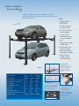
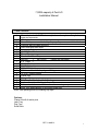
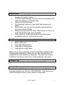
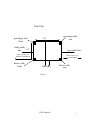
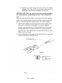
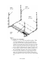
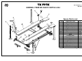
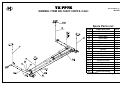
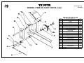
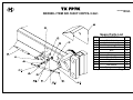
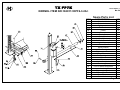
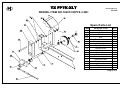
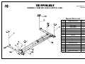
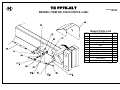
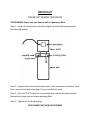
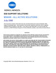
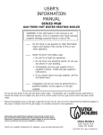
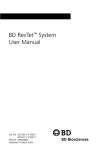
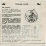
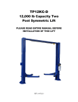
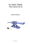
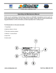
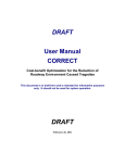
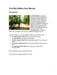
FP7K&FP7KXLT
7000l
bCapaci
t
y
Ser
vi
ce/
St
or
ageLi
f
t
I
ns
t
a
l
l
a
t
i
o
n& Ope
r
a
t
i
o
nMa
nua
l
REV A-080113
7,000 LB. / 9,000 LB.
STORAGE / SERVICE
LIFT
7,000 lb. / 9,000 lb. capacity and large 3” cylinder,
one-piece diamond-plate runways and scratch-resistant
powder coat paint.
Features:
✦
7,000 lb./ 9,000 lb.
lifting capacity
✦
Carriages completely
enclosed for safety
✦
Aircraft quality cables
rated at 14,500 lbs.
✦
18” wide runways
formed with one piece
3
⁄16” non-skid diamond
plate
✦
Hydraulic pump available
in 110 or 220 vac
✦
Easy operation—lock
handle is located by
power unit minimizing
any bending or squatting
✦
Large 3” diameter
cylinder is located
safely under runway
FP7K
Storage / Service lift
Solid Deck Option
Large storage area. Two diamond
plate platforms drop between
tracks for storage of snowmobiles,
ATVs and garden equipment.
Available in steel or lightweight
aluminum.
–Options
SPECIFICATIONS
FP9K
FP7K
(Not Shown)
Lifting capacity
Overall length (to outside base plates)
Total width (to outside base plates)
Overall height
Track length (without ramp)
Track width
Rate of lift
Width between posts
Maximum clearance under tracks
Shipping weight
9,000 lbs.
175”
103.38”
82”
165”
18 5⁄8”
90 sec.
94”
68”
1,485 lbs.
FP7K-XLT
(Not Shown)
7,000 lbs.
170”
108.38”
82”
160”
18 5⁄8”
90 sec.
99”
64”
1,485 lbs.
7,000 lbs.
190”
108.38”
92”
180”
18 5⁄8”
100 sec.
99”
74”
1,680 lbs.
One-Step Caster Kit
Easy to install with no tools— simply pin
them on, lower lift, casters automatically
lift the columns; allows mobility with or
without a vehicle; turn lift sideways to
park two vehicles underneath.
Aluminum Approach Ramps
These lightweight ramps weigh only
18 lbs. each compared with the
53 lbs. of standard ramps.
Stackable Poly Drip Trays, 3
Lightweight polyethylene; stackable:
simply slide to back and stack!
8” or 12” widths.
TUXEDO DISTRIBUTORS LIMITED WARRANTY
Structural Warranty:
The following parts and structural components carry a five year warranty:
Columns
Legs
Top Rail Beam
Carriages
Uprights
Arms Swivel Pins
Tracks Overhead Beam Cross Rails
Limited One-Year Warranty:
Tuxedo Distributors, LLC (“Tuxedo”) offers a limited one-year warranty to the original purchaser of
Tuxedo lifts and Wheel Service in the United States and Canada. Tuxedo will replace, without charge, any
part found defective in materials or workmanship under normal use, for a period of one year after purchase.
The purchaser is responsible for all shipping charges. This warranty does not apply to equipment that has
been improperly installed or altered or that has not been operated or maintained according to specifications.
Other Limitations:
This warranty does not cover:
1.
2.
3.
4.
Parts needed for normal maintenance
Wear parts, including but not limited to cables, slider blocks, chains, rubber pads and pulleys
Replacement of lift and tire changer cylinders after the first 30 days. A seal kit and installation
instructions will be sent for repairs thereafter.
On-site labor
Upon receipt, the customer must visually inspect the equipment for any potential freight damage before
signing clear on the shipping receipt. Freight damage is not considered a warranty issue and therefore must
be noted for any potential recovery with the shipping company.
The customer is required to notify Tuxedo of any missing parts within 72 hours. Timely notification must
be received to be covered under warranty.
Tuxedo will replace any defective part under warranty at no charge as soon as such parts become available
from the manufacturer. No guarantee is given as to the immediate availability of replacement parts.
Tuxedo reserves the right to make improvements and/or design changes to its lifts without any obligation
to previously sold, assembled or fabricated equipment.
There is no other express warranty on the Tuxedo lifts and this warranty is exclusive of and in lieu of all
other warranties, expressed or implied, including all warranties of merchantability and fitness for a
particular purpose.
To the fullest extent allowed by law, Tuxedo shall not be liable for loss of use, cost of cover, lost profits,
inconvenience, lost time, commercial loss or other incidental or consequential damages.
This Limited Warranty is granted to the original purchaser only and is not transferable or
assignable.
Some states do not allow exclusion or limitation of consequential damages or how long an
implied warranty lasts, so the above limitations and exclusions may not apply. This warranty
gives you specific legal rights and you may have other rights, which may vary from state to state.
1905 N Main St Suite C, Cleburne, TX 76033
Ph 817-558-9337
Fax 817-558-9740
7,000lb capacity 4 Post Lift
Installation Manual
Parts Checklist
1
Main side track with 9/16” hole on cylinder end complete with cylinder,
hose and connector
1
Offside track
2
Cross Rails pre-assembled with pulleys, pulley covers, and slider blocks
4
Columns with top caps and bolts
2
Short rods with heim ends
1
Long rod with heim ends
1
½” x 50” Bent Rod
4
Ramp Clips
4
Removable Wheel Stop
Ms7000
//
ms7000XLT
cables with hardware
1
8’ 4” Cable //
1
13’ 4 ¾” Cable
//
1
21’ ½” Cable //
1
26” 1 ¾” Cable //
1
71” Hose with anti-kink spring and fittings
2
18” x 80” Plastic Sheets
1
Power Unit
2
Drive on Ramps
1
Bolt Box that includes the following:
16
Anchors for optional bolting to floor
8
Bolts, nuts, washers and lock washers for securing ramps
4
Bolts, nuts and washers for mounting power unit
Note: save packing bolts for installing top caps
Options:
Caster Kit with 4 caster pins
Jack Tray
Drip Tray
Solid Deck
REV A-080113
1
Important Notes
1.
2.
3.
4.
5.
6.
7.
Always inspect the lift for damage and make note of any
damage on the bill of lading.
In case of freight damage, call the truck line immediately and
report the damage as a freight claim.
Always read the directions.
Do a thorough inventory of your parts and measure your
cables.
Never raise a car until you have double-checked all bolts
and nuts and hose fittings.
Always level and check for leaks. Never stand or store a car
under this lift without the locks engaged.
Please obtain a qualified electrician to provide wiring in
compliance with your local electrical codes.
Tools Required
1.
2.
3.
4.
5.
Metric Open or box end wrenches
Metric socket set.
Large adjustable wrench.
Vise grips or locking pliers.
Large punch to align holes.
Make sure you have extra help or heavy duty lifting equipment when
unloading and assembling. Make sure you have enough room to
install the lock rods, at least a 9’ clearance. The power unit may be
installed on the driver’s front corner or the passenger rear corner.
Installation Time
The lift should take between four and six hours to install.
Hydraulic Oil
Use AW-32 or ISO-32 hydraulic oil for your power unit. (10wt nondetergent hydraulic oil) DO NOT USE DEXRON. It will damage the
seals and shorten the life of your hydraulic components.
REV A-080113
2
Floor Plan
passenger side
front
170”
front guide 112”
line
rear guide line
allow at least 6’ for
handle rod installation
drivers side
front
passenger side
rear
allow at least 9’ for
T rod installation
side lines
drivers side
rear
figure 1
REV A-080113
3
BEFORE ATTEMPTING TO ASSEMBLE THIS LIFT
STUDY FLOOR PLAN CAREFULLY.
MAKE SURE YOU HAVE ENOUGH ROOM. KEEP
FLOOR PLAN AREA CLEAR OF LIFT COMPONENTS
UNTIL THEY ARE READY TO BE INSTALLED.
TAKE SPECIAL NOTE OF SPACE NEEDED FOR
SAFETY ROD ASSEMBLY
A.COLUMN AND CROSSBAR ASSEMBLY
1. Locate the four columns. One column has a bracket for the
power unit. Determine placement of power unit column.
(drivers side front or passenger side rear)For this
installation we will be placing the power unit in the
drivers side front position.
2. Take column with the power unit bracket and stand it up in
the drivers side front corner (see fig.1) with the opening
facing in and the lock blocks located on the right side of the
column opening (as you stand facing the opening) along the
front guide line.
3. Stand up another column in passenger side front position.
Make sure that the opening is facing in towards the drivers
side front column and the lock blocks are on the left side of
the column opening, along the front guide line.
4. Tilt the columns back and lay each on the ground along the
side guide lines. Remove the top caps.
5. Place a crossbar at the top of the 2 columns. Be sure that the
spring loaded lock latches at either end of the crossbar are
facing up, with bevel side up.
6. With a helper slide the cross rail into the top of the columns.
In order to lower the cross rail all the way down it will be
necessary to manually hold the lock latches out of the way
of the stop blocks. Release latches to engage the lowest lock
blocks(16” off the ground). Stand the assembly up.
7. Repeat process for rear columns and cross rail. Make sure
the lock blocks on the driver’s side rear column are on the
left of the column opening along the rear guide line, and that
the lock blocks on the passenger side rear column are on the
right side of the column opening along the rear guide line.
When complete the cross rails will be approximately 160”
apart.
REV A-080113
4
B. TRACK INSTALLATION
1. Locate the track with the cylinder attached underneath. Now
find the ¾” hole in the side of the ramp. This hole will be
positioned next to the power post (driver’s side front). The
ledge running down the side of the ramp always goes on the
inside. (it’s used to support the drip trays and other options)
2. To aid lifting, position the track on two 2x4s or blocks on
the floor just outside the column assemblies taking care to
keep ledge facing in.
3. With two people on each end of the track, lift the ends of the
track onto the cross rails. You will need to walk one end at a
time into the floor plan area to clear the column assemblies.
Using a large punch, line up the holes in the cross rail with
those on the track and temporarily bolt together using one
bolt in each end.
4. Install offside track by repeating steps 1 through 3.
Remember to keep the ledge running the length of track
facing to the inside.
5. Locate the 4 drop-in ramp clips and working on one end at a
time, carefully remove the track bolts, install the ramp clip,
with spacing collars towards cross rail, and reinstall using
both bolts and tighten.
C. CABLE INSTALLATION
1. Lay out all cables and measure from the inside of the button
end to the end of the cable bolt to insure proper cable
lengths. See fig.3 for measurements.
2. In order to attach the cable buttons to the mounting bracket
on the end of the ram, the ram must be extended. Below are two
suggested methods of extending ram
a. Using the cable mounting-bracket on the end of the
ram, pull the ram out with a come-along.
REV A-080113
5
b. Position yourself under the track with your hands
gripping the edge of the track, then put your feet
against the cable bracket and push the ram out.
IMPORTANT: Take care not to score the ram when pulling
the ram manually or tightening the nut. This will ruin the
seal.
Since the nub end of the cable is easier end to feed through the
pulley, start with the pulley at the end of the crossbar and work
your way back to the ram. (Refer to fig 3 for cable routing.)
3. Install cable buttons into the appropriate slots in thick plate
and secure with slots on thin plate. (see fig3a) Tighten
enough so the nylock nut is fully threaded onto the head of
the ram and that at least three threads are exposed past the
top of the nut. The cable bracket should still be able to move
freely on the ram head.
4. Run the threaded cable ends into the hole in the top caps and
secure with washer and nylock nut.
Cable Hookup
fig 3a
REV A-080113
6
D. HYDRAULIC ASSEMBLY
1. Find the 4, 1” x 5/16” bolts, nuts and lock washers. With
one helper holding the power unit, line up the holes on
power unit with the holes in mounting bracket and attach
with the four mounting bolts. Remove the plastic-cap from
the port on the power unit and attach the o-ring elbow. Do
not over tighten, backing nut and o-ring will complete seal.
2. Connect power unit hose (the hose with the spring on it) to
the o-ring fitting on the power unit. Do not over-tighten.
3. On the end of the cylinder hose, located under the track,
remove the backing nut from the bulkhead fitting, insert
fitting through hole in side of track and secure with backing
nut.
REV A-080113
7
4. Attach loose end of power unit hose to the bulk head fitting
5. Use 3 gallons of ISO-32 or AW-32 hydraulic oil (can be
purchased at local auto parts discount supplier) to fill
reservoir (10wt non-detergent hydraulic oil)
F. LOCK LINKAGE ASSEMBLY
Remember: This manual is installing the power column at
the driver’s side front position
1. The single point safety lock is a system of connecting rods
and linkage that disengage the four lock latches that secure
the lift to each column. Locate the 6 rods:
2 long rods, 2 short rods, 1 handle, 1 tee.
2. Starting with the handle, insure that spacer is installed over
threaded end of handle and inset rod into hole on cross bar
near power column. Take care to run rod through rod guide
located under track.
3. Install long rod into the hole on the cross rail near the
driver’s rear column. Make sure the spacer is on the rod and
take care to run rod through rod guide.
4. Thread nut onto ends of handle rod and “T” rod. With the T
on the handle set at 12:00 o’clock and the T on the long rod
set at 12:30 when viewed from power unit end, attach
coupler and tighten with lock nuts. Rod should be secure but
free enough to swing.
5. Starting at the power unit end, attach linkage bolt at one end
of the long ¼” rod into the hole located in the lock latch near
the passenger front column and secure with nut. Attach the
other end of the long ¼” rod to the top of the handle T
6. Repeat using short ¼” rod attaching to the lock latch near
the driver’s side front column and attach the other end to the
bottom of the handle T
7. Repeat process on rear cross rail.
REV A-080113
8
G. FINAL ADJUSTMENTS
1. Please obtain a qualified electrician to provide wiring in
compliance with your local electrical codes.
2. Depress power up button for 10 seconds. Then while
continuing to hold power button open release lever for
another 5-10 seconds, allowing air to be bled from the
system.
3. Run power until tracks begin to rise. Go to the top of each
column and tighten any cables that are slack. All cables
should have even tension and platform must hang level.
(Check by using a level on the crossbars). Never adjust
cables with a vehicle on the lift. This will damage threads on
cable.
4. Run lift up and down a few times to insure that the locks are
engaging uniformly and that the release mechanism is
functioning properly. Have helper check to be sure that far
side lock latches are disengaging as fully as the near side
lock latches
5. With lift all the way down, install the approach ramps and
carefully drive a vehicle onto the tracks.
6. Run the lift up and down a few times rechecking all
function. If cables need to be adjusted vehicle must be
removed first or damage to threads on cable will occur.
REV A-080113
9
TX FP7K
Kernel Edtion 1.0
Mar.2008
KERNEL ITEM NO.163011<DPF4-3.2A>
Spare Parts List
ITEM
DESCRIPTION
QTY
Column parts
2
Top plate parts
2
Column parts
2
Top plate parts
2
Galvanized bolt
12
Flat washer
24
Galvanized nut
12
Punway parts
1
Brae
2
Punway parts
1
Cross beam parts
2
Toolbox parts
1
Bolt
8
Rub blocks
4
Ramp broad
4
Galvanized flat washer
8
Spring washer
8
Galvanized nut
8
* Easily Worn Parts
Page 1 of 5
1
2
3
4
5
5.1
5.2
6
7
8
9
10
11
12
13
14
15
16
TX FP7K
Kernel Edtion 1.0
Mar.2008
KERNEL ITEM NO.163011<DPF4-3.2A>
Spare Parts List
ITEM
DESCRIPTION
QTY
Steel cable
1
Steel cable
1
Steel cable
1
Steel cable
1
Lock nut
4
Flat washer
4
Pulley
10
Core shaft
4
Sheath
2
Sheath
2
Flat washer
6
Bush
6
Bolt
4
Aunectent shaft
1
Galvanized nut
2
Bolt
2
Galvanized nut
2
Up-rights
1
Untie lock handle
1
* Easily Worn Parts
Page 2 of 5
17
18
19
20
21
22
23
24
25
26
26.1
26.2
26.3
26.4
26.5
26.6
26.7
26.8
43
TX FP7K
Kernel Edtion 1.0
Mar.2008
KERNEL ITEM NO.163011<DPF4-3.2A>
Spare Parts List
ITEM
DESCRIPTION
QTY
Pulley
10
Pole
2
Sheath
8
Bolt
12
Retropack bolt
4
Wrest spring(right)
2
Bushing
4
Spring sheath
4
Rubber block
8
Washer
32
Flat washer
16
Flat washer
24
Cross beam parts
2
Galvanized bolt
8
Galvanized nut
8
Cover A
2
Flat washer
12
Bush
4
* Easily Worn Parts
Page 3 of 5
23
27
28
29
30
31
32
33
34
35
35.1
35.2
36
37
38
39
40
41
TX FP7K
Kernel Edtion 1.0
Mar.2008
KERNEL ITEM NO.163011<DPF4-3.2A>
Spare Parts List
ITEM
DESCRIPTION
QTY
Bakelite ball
1
Untie lock handle
1
Wrest spring(left)
2
Cover B
2
Bolt
8
Cover
4
Bushing
6
Small shaft
4
Small shaft
4
Cover
4
Flat washer
8
Spring washer
8
* Easily Worn Parts
Page 4 of 5
42
43
44
45
47
48
50
51
51.1
51.2
51.3
51.4
TX FP7K
Kernel Edtion 1.0
Mar.2008
KERNEL ITEM NO.163011<DPF4-3.2A>
Spare Parts List
ITEM
DESCRIPTION
QTY
52
53
53.1
53.2
54
55
56
57
58
59
60
61
62
63
64
64.1
64.2
65
66
67
68
69
70
71
72
73
74
Galvanized bolt
Galvanized nut
Spring washer
Flat washer
Caster
Raw pin
Plank parts
Spring block
Hydraulic cylinder pin
Shaft sheath
Hydraulic pump
Flat washer
Spring washer
Galvanized bolt
Right-angled Tie-in
Hydraulic extention
Bushing
Oil hose
Oil hose
Hydraulic cylinder
Wheel stop plates
Front of wheel stop plates
Locknut
Right-angled Tie-in
Right-angled Tie-in
Nut
Galvanized nut
16
16
16
16
4
4
4
4
1
2
1
8
4
4
1
1
1
1
1
1
1
1
1
1
1
1
4
* Easily Worn Parts
Page 5 of 5
TX FP7K-XLT
Kernel Edtion 1.0
Mar.2008
KERNEL ITEM NO.163013<DPF4-3.2B>
Spare Parts List
ITEM
DESCRIPTION
QTY
Column parts
2
Top plate parts
2
Column parts
2
Top plate parts
2
Galvanized bolt
12
Flat washer
24
Galvanized nut
12
Punway parts
1
Brae
2
Punway parts
1
Cross beam parts
2
Toolbox parts
1
Bolt
8
Rub blocks
4
Ramp broad
4
Galvanized flat washer
8
Spring washer
8
Galvanized nut
8
* Easily Worn Parts
Page 1 of 5
1
2
3
4
5
5.1
5.2
6
7
8
9
10
11
12
13
14
15
16
TX FP7K-XLT
Kernel Edtion 1.0
Mar.2008
KERNEL ITEM NO.163013<DPF4-3.2B>
Spare Parts List
ITEM
DESCRIPTION
QTY
Pulley
10
Pole
2
Sheath
8
Bolt
12
Retropack bolt
4
Wrest spring(right)
2
Bushing
4
Spring sheath
4
Rubber block
8
Washer
32
Flat washer
16
Flat washer
24
Cross beam parts
2
Galvanized bolt
8
Galvanized nut
8
Cover A
2
Flat washer
12
Bush
4
* Easily Worn Parts
Page 3 of 5
23
27
28
29
30
31
32
33
34
35
35.1
35.2
36
37
38
39
40
41
TX FP7K-XLT
Kernel Edtion 1.0
Mar.2008
KERNEL ITEM NO.163013<DPF4-3.2B>
Spare Parts List
ITEM
DESCRIPTION
QTY
Steel cable
1
Steel cable
1
Steel cable
1
Steel cable
1
Lock nut
4
Flat washer
4
Pulley
10
Core shaft
4
Sheath
2
Sheath
2
Flat washer
6
Bush
6
Bolt
4
Aunectent shaft
1
Galvanizedn nut
2
Bolt
2
Galvanized nut
2
Up-rights
1
Untie lock handle
1
* Easily Worn Parts
Page 2 of 5
17
18
19
20
21
22
23
24
25
26
26.1
26.2
26.3
26.4
26.5
26.6
26.7
26.8
43
TX FP7K-XLT
Kernel Edtion 1.0
Mar.2008
KERNEL ITEM NO.163013<DPF4-3.2B>
Spare Parts List
ITEM
DESCRIPTION
QTY
52
53
53.1
53.2
54
55
56
57
58
59
60
61
62
63
64
64.1
64.2
65
66
67
68
69
70
71
72
73
74
Galvanized bolt
Galvanized nut
Spring washer
Flat washer
Caster
Raw pin
Plank parts
Spring block
Hydraulic cylinder pin
Shaft sheath
Hydraulic pump
Flat washer
Spring washer
Galvanizantion bolt
Right-angled Tie-in
Hydraulic extention
Bushing
Oil hose
Oil hose
Hydraulic cylinder
Wheel stop plates
Front of wheel stop plates
Locknut
Right-angled Tie-in
Right-angled Tie-in
Nut
Galvanized nut
16
16
16
16
4
4
4
4
1
2
1
8
4
4
1
1
1
1
1
1
1
1
1
1
1
1
4
* Easily Worn Parts
Page 5 of 5
TX FP7K-XLT
Kernel Edtion 1.0
Mar.2008
KERNEL ITEM NO.163013<DPF4-3.2B>
Spare Parts List
ITEM
DESCRIPTION
QTY
Bakelite ball
1
Untie lock handle
1
Wrest spring(left)
2
Cover B
2
Bolt
8
Cover
4
Bushing
6
Small shaft
4
Small shaft
4
Cover
4
Flat washer
8
Spring washer
8
* Easily Worn Parts
Page 4 of 5
42
43
44
45
47
48
50
51
51.1
51.2
51.3
51.4
IMPORTANT
POWER UNIT PRIMING PROCEDURE
THE PROBLEM: Power unit runs fine but will not pump any fluid.
Step 1 – Locate the check valve, the flush plug to the left of the lowering valve.
(See drawing below.)
Step 2 – Using an Allen wrench and shop towel – with shop towel in place to catch
fluid – loosen the check valve plug 2 ½ turns to allow it to leak.
Step 3 – Push the START button for one second, then release for three seconds.
Repeat these steps until unit starts pumping fluid.
Step 4 – Tighten the check valve plug.
YOUR POWER UNIT SHOULD BE PRIMED