1
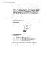
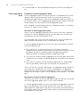
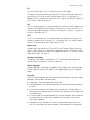
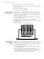
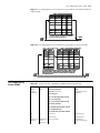
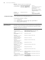
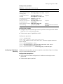
3Com® Switch 4200G Family
Configuration Guide
4200G 12-Port (3CR17660-91)
4200G 24-Port (3CR17661-91)
4200G 48-Port (3CR17662-91)
www.3Com.com
Part Number: 10014915 Rev. AD
Published: May 2007
3Com Corporation
350 Campus Drive
Marlborough, MA
USA 01752-3064
Copyright © 2006, 3Com Corporation. All rights reserved. No part of this documentation may be reproduced in any form or
by any means or used to make any derivative work (such as translation, transformation, or adaptation) without written
permission from 3Com Corporation.
3Com Corporation reserves the right to revise this documentation and to make changes in content from time to time
without obligation on the part of 3Com Corporation to provide notification of such revision or change.
3Com Corporation provides this documentation without warranty, term, or condition of any kind, either implied or
expressed, including, but not limited to, the implied warranties, terms or conditions of merchantability, satisfactory quality,
and fitness for a particular purpose. 3Com may make improvements or changes in the product(s) and/or the program(s)
described in this documentation at any time.
If there is any software on removable media described in this documentation, it is furnished under a license agreement
included with the product as a separate document, in the hard copy documentation, or on the removable media in a
directory file named LICENSE.TXT or !LICENSE.TXT. If you are unable to locate a copy, please contact 3Com and a copy will
be provided to you.
UNITED STATES GOVERNMENT LEGEND
If you are a United States government agency, then this documentation and the software described herein are provided to
you subject to the following:
All technical data and computer software are commercial in nature and developed solely at private expense. Software is
delivered as “Commercial Computer Software” as defined in DFARS 252.227-7014 (June 1995) or as a “commercial item”
as defined in FAR 2.101(a) and as such is provided with only such rights as are provided in 3Com’s standard commercial
license for the Software. Technical data is provided with limited rights only as provided in DFAR 252.227-7015 (Nov 1995) or
FAR 52.227-14 (June 1987), whichever is applicable. You agree not to remove or deface any portion of any legend provided
on any licensed program or documentation contained in, or delivered to you in conjunction with, this User Guide.
Unless otherwise indicated, 3Com registered trademarks are registered in the United States and may or may not be registered
in other countries.
3Com and the 3Com logo are registered trademarks of 3Com Corporation.
Cisco is a registered trademark of Cisco Systems, Inc.
Funk RADIUS is a registered trademark of Funk Software, Inc.
Aegis is a registered trademark of Aegis Group PLC.
Intel and Pentium are registered trademarks of Intel Corporation. Microsoft, MS-DOS, Windows, and Windows NT are
registered trademarks of Microsoft Corporation. Novell and NetWare are registered trademarks of Novell, Inc. UNIX is a
registered trademark in the United States and other countries, licensed exclusively through X/Open Company, Ltd.
IEEE and 802 are registered trademarks of the Institute of Electrical and Electronics Engineers, Inc.
All other company and product names may be trademarks of the respective companies with which they are associated.
ENVIRONMENTAL STATEMENT
It is the policy of 3Com Corporation to be environmentally-friendly in all operations. To uphold our policy, we are committed
to:
Establishing environmental performance standards that comply with national legislation and regulations.
Conserving energy, materials and natural resources in all operations.
Reducing the waste generated by all operations. Ensuring that all waste conforms to recognized environmental standards.
Maximizing the recyclable and reusable content of all products.
Ensuring that all products can be recycled, reused and disposed of safely.
Ensuring that all products are labelled according to recognized environmental standards.
Improving our environmental record on a continual basis.
End of Life Statement
3Com processes allow for the recovery, reclamation and safe disposal of all end-of-life electronic components.
Regulated Materials Statement
3Com products do not contain any hazardous or ozone-depleting material.
CONTENTS
ABOUT THIS GUIDE
Organization of the Manual
Intended Readership 2
Conventions
2
Related Manuals 3
1
1
CLI OVERVIEW
Introduction to the CLI 1
Command Level/Command View
CLI Features 6
Terminal Display 7
2
1
LOGGING INTO AN ETHERNET SWITCH
Logging into an Ethernet Switch 9
Introduction to the User Interface 9
3
LOGGING IN THROUGH THE CONSOLE PORT
Introduction 11
Setting up the Connection to the Console Port 11
Console Port Login Configuration 13
Console Port Login Configuration with Authentication Mode Being None 15
Console Port Login Configuration with Authentication Mode Being Password 18
Console Port Login Configuration with Authentication Mode Being Scheme 21
4
LOGGING IN USING MODEM
Introduction 25
Configuration on the Administrator Side
Configuration on the Switch Side 25
Modem Connection Establishment 26
5
LOGGING IN THROUGH WEB-BASED NETWORK MANAGEMENT SYSTEM
Introduction 29
HTTP Connection Establishment
6
29
LOGGING IN THROUGH NMS
Introduction 33
Connection Establishment Using NMS
7
25
33
CONTROLLING LOGIN USERS
Introduction 35
Controlling Telnet Users 35
Controlling Network Management Users by Source IP Addresses
Controlling Web Users by Source IP Address 39
37
2
CONTENTS
8
CONFIGURATION FILE MANAGEMENT
Introduction to Configuration File 41
Configuration File-Related Configuration
9
VLAN CONFIGURATION
VLAN Overview 43
VLAN Configuration 44
Displaying a VLAN 44
VLAN Configuration Example
10
41
45
MANAGEMENT VLAN CONFIGURATION
Introduction to Management VLAN 47
Management VLAN Configuration 47
Displaying and Debugging Management VLAN
11
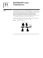
DHCP/BOOTP CLIENT CONFIGURATION
Introduction to DHCP Client 51
Introduction to BOOTP Client 53
DHCP/BOOTP Client Configuration
12
49
53
VOICE VLAN CONFIGURATION
Voice VLAN Configuration 55
Voice VLAN Configuration 57
Voice VLAN Displaying and Debugging 59
Voice VLAN Configuration Example 59
13
GVRP CONFIGURATION
Introduction to GVRP 61
GVRP Configuration 63
Displaying and Maintaining GVRP
14
65
BASIC PORT CONFIGURATION
Ethernet Port Overview 67
Configuring Ethernet Ports 69
Ethernet Port Configuration Example 73
Troubleshooting Ethernet Port Configuration
15
74
LINK AGGREGATION CONFIGURATION
Overview 75
Link Aggregation Configuration 79
Displaying and Maintaining Link Aggregation Information
Link Aggregation Configuration Example 82
16
PORT ISOLATION CONFIGURATION
Port Isolation Overview
85
81
CONTENTS
Port Isolation Configuration 85
Displaying Port Isolation 85
Port Isolation Configuration Example
17
PORT SECURITY CONFIGURATION
Port Security Configuration 87
Displaying Port Security 90
Port Security Configuration Example
18
85
91
MAC ADDRESS TABLE MANAGEMENT
Overview 93
MAC Address Table Management 95
Displaying and Maintaining a MAC Address Table
Configuration Example 96
19
96
LOGGING IN THROUGH TELNET
Introduction 99
Telnet Configuration with Authentication Mode Being None 100
Telnet Configuration with Authentication Mode Being Password 102
Telnet Configuration with Authentication Mode Being Scheme 105
Telnet Connection Establishment 109
20
MSTP CONFIGURATION
MSTP Overview 113
Root Bridge Configuration 118
Leaf Node Configuration 131
The mCheck Configuration 135
Protection Function Configuration 136
BPDU Tunnel Configuration 139
Digest Snooping Configuration 141
Rapid Transition Configuration 142
MSTP Displaying and Debugging 145
MSTP Implementation Example 145
21
802.1X CONFIGURATION
Introduction to 802.1x 149
802.1x Configuration 158
Basic 802.1x Configuration 158
Timer and Maximum User Number Configuration
Advanced 802.1x Configuration 160
Displaying and Debugging 802.1x 162
Configuration Example 162
22
HABP CONFIGURATION
Introduction to HABP 165
HABP Server Configuration 165
159
3
4
CONTENTS
HABP Client Configuration 166
Displaying and Debugging HABP 166
23
AAA&RADIUS CONFIGURATION
Overview 167
Configuration Tasks 173
AAA Configuration 174
RADIUS Configuration 179
Displaying AAA&RADIUS Information 186
AAA&RADIUS Configuration Example 187
Troubleshooting AAA&RADIUS Configuration
24
189
CENTRALIZED MAC ADDRESS AUTHENTICATION CONFIGURATION
Centralized MAC Address Authentication Overview 191
Centralized MAC Address Authentication Configuration 191
Displaying and Debugging Centralized MAC Address Authentication 193
Centralized MAC Address Authentication Configuration Example 194
25
ARP CONFIGURATION
Introduction to ARP 195
Introduction to Gratuitous ARP 197
ARP Configuration 198
Gratuitous ARP Packet Learning configuration
Displaying and Debugging ARP 199
26
ACL CONFIGURATION
ACL Overview 201
Configuring Time Ranges 202
Defining Basic ACLs 203
Defining Advanced ACLs 204
Defining Layer 2 ACLs 207
Applying ACLs on Ports 209
Displaying and Debugging ACL Configuration
ACL Configuration Examples 210
27
199
QOS CONFIGURATION
Introduction to QoS 213
Priority Mapping 221
QoS Supported by Switch 4200G 223
Configuring Priority Mapping 224
Configuring TP 229
Configuring TS 230
Configuring Queue-scheduling 231
Configuring Traffic Statistics 232
Setting the Precedence of Protocol Packet
Displaying and Maintaining QoS 234
QoS Configuration Example 235
233
210
CONTENTS
28
CONFIGURATION FOR MIRRORING FEATURES
Mirroring Features 237
Mirroring Supported by Switch 4200G 239
Mirroring Configuration 239
Displaying and Debugging Mirroring 248
29
IGMP SNOOPING CONFIGURATION
Overview of IGMP Snooping 249
IGMP Snooping Configuration 252
Displaying Information About IGMP Snooping
IGMP Snooping Configuration Example 256
Troubleshooting IGMP Snooping 259
30
256
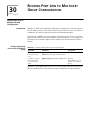
ROUTING PORT JOIN TO MULTICAST GROUP CONFIGURATION
Routing Port Join to Multicast Group Configuration
31
261
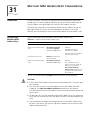
MULTICAST MAC ADDRESS ENTRY CONFIGURATION
Introduction 263
Configuring a Multicast MAC Address Entry 263
Displaying Multicast MAC Address Configuration 264
32
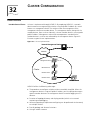
CLUSTER CONFIGURATION
Cluster Overview 265
Management Device Configuration 268
Member Device Configuration 271
Intra-Cluster Configuration 272
Displaying and Maintaining a Cluster 272
HGMP V2 Configuration Example 273
33
SNMP CONFIGURATION
SNMP Overview 277
Configuring SNMP Basic Functions 279
Configuring Trap 281
Setting the Logging Function for Network Management
Displaying SNMP 282
SNMP Configuration Example 282
34
RMON CONFIGURATION
Introduction to RMON 285
RMON Configuration 287
Displaying and Debugging RMON 288
RMON Configuration Example 288
35
NTP CONFIGURATION
Introduction to NTP
291
282
5
6
CONTENTS
NTP Implementation Mode Configuration 295
Access Control Permission Configuration 297
NTP Authentication Configuration 297
Configuration of Optional NTP Parameters 299
Displaying and Debugging NTP 300
Configuration Example 300
36
SSH TERMINAL SERVICES
SSH Terminal Services
SFTP Service 317
37
309
FILE SYSTEM MANAGEMENT
File Attribute Configuration 325
File System Configuration 326
Testing Tools for Network Connection
38
331
FTP AND TFTP CONFIGURATION
FTP Configuration 333
TFTP Configuration 339
39
INFORMATION CENTER
Information Center Overview 343
Information Center Configuration 345
Displaying and Debugging Information Center 350
Information Center Configuration Example 350
40
BOOTROM AND HOST SOFTWARE LOADING
Introduction to Loading Approaches
Local Software Loading 353
Remote Software Loading 361
41
353
Basic System Configuration and Debugging
Basic System Configuration 365
Displaying the System Status 367
System Debugging 367
42
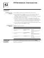
IP PERFORMANCE CONFIGURATION
IP Performance Configuration 371
Displaying and Debugging IP Performance 371
Troubleshooting the IP Performance Configuration
43
NETWORK CONNECTIVITY TEST
Network Connectivity Test
373
372
CONTENTS
44
DEVICE MANAGEMENT
Introduction to Device Management 375
Device Management Configuration 375
Displaying the Device Management Configuration 376
Remote Switch Update Configuration Example 376
45
CONFIGURATION OF NEWLY ADDED CLUSTER FUNCTIONS
Introduction to the Newly Added Cluster Functions 379
Displaying and Debugging a Cluster 389
Configuration Example for Newly Added Cluster Functions
46
DHCP RELAY CONFIGURATION
Introduction to DHCP Relay 393
DHCP Relay Configuration 395
Option 82 Supporting Configuration 397
DHCP Relay Displaying 399
DHCP Relay Configuration Example 399
Troubleshooting DHCP Relay 400
47
STATIC ROUTE CONFIGURATION
Introduction to Static Route 401
Static Route Configuration 402
Displaying and Debugging Static Route 403
Typical Static Route Configuration Example 403
Static Route Fault Diagnosis and Troubleshooting 404
48
UDP HELPER CONFIGURATION
Overview of UDP Helper
405
390
7
8
CONTENTS
ABOUT THIS GUIDE
This guide provides information about configuring your network using the
commands supported on the 3Com® Switch 4200-G Family.
The descriptions in this guide applies to the Switch 4200-G.
Organization of the
Manual
The Switch 4200 Family Configuration Guide consists of the following chapters:
■
CLI Overview—Provides an introduction to the CLI interface.
■
Logging In—Provides information on the different ways to log into the switch.
■
Configuration File System Management—Details the Configuration File
System Management.
■
Address Management—Details hoe to configure the switch on which the
Address Manage (AM) feature is enabled.
■
VLAN Operation—Details how to configure VLANs.
■
DHCP—Details Dynamic Host Configuration Protocol.
■
Voice-VLAN—Details configuration information to create Voice-VLAN.
■
GVRP Configuration—Details GARP VLAN Registration Protocol
configuration.
■
Port Operation—Details how to configure Ethernet ports.
■
Link Aggregation—Details how to aggregating several ports together
■
Port Isolation—Details how to configure ports to be controlled on Layer 2.
■
DLDP—Details overview and fundamentals for Device Link Detection Protocol.
■
MAC Address Table Management—Details MAC address table
configuration.
■
MSTP—Details Multiple spanning tree protocol.
■
802.1x Configuration—Details how to configure 802.1x.
■
HABP Configuration—Details how to configure HABP
■
AAA &RADIUS—Details AAA and RADIUS Configuration.
■
EAD—Details Endpoint Admission Defense Configuration.
■
Centralized MAC address authentication—Details Centralized MAC
address authentication configuration.
■
ARP—Details Address Resolution Protocol table configuration.
■
DHCP—Details Dynamic Host Configuration Protocol.
■
ACL Configuration—Details how to configure QoS/ACL..
2
ABOUT THIS GUIDE
Intended Readership
Conventions
■
QoS—Details Quality of Service.
■
Mirroring—Details how to configure Mirroring.
■
IGMP Snooping—Details Internet Group Management Protocol Snooping
■
Multicast Protocol—Details how to configure multicast protocols.
■
Clustering—Details Clustering Configuration.
■
SNMP—Details Simple Network Management Protocol Configuration.
■
RMON—Details Remote Monitoring Configuration.
■
NTP—Details Network time protocol.
■
SSH—Details Secure Shell authentication.
■
File System Management—Details how to configure the file system
management.
■
FTP and TFTP—Details how to configure the FTP and TFTP protocols.
■
Information Center—Details how to configure the Information Center
■
BootROM and Host Software—Details how to how to load BootROM and
host software to a switch
■
Basic System Configuration—Details how to how to configure a basic
system.
■
IP Performance Configuration—Details how to configure routing protocols
■
Network Protocol Operation—Details how to configure network protocols
■
Network Connectivity Tests—Details how to perform a connectivity test.
■
Device Management—Details how to manage devices.
■
VLAN-VPN—Details configuration information to create VLAN-VPNs.
■
DHCP Relay—Details Dynamic Host Configuration Protocol relay
configuration.
■
Static Route—Details Static Route Configuration.
■
UDP Helper—Details UDP Configuration.
The manual is intended for the following readers:
■
Network administrators
■
Network engineers
■
Users who are familiar with the basics of networking
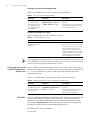
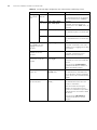
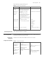
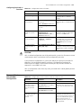
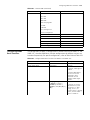
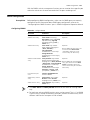
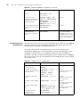
This manual uses the following conventions:
Table 1 Icons
Icon
Notice Type
Description
Information note
Information that describes important features or instructions.
Caution
Information that alerts you to potential loss of data or
potential damage to an application, system, or device.
Related Manuals
3
Table 1 Icons (Continued)
Icon
Notice Type
Description
Warning
Information that alerts you to potential personal injury.
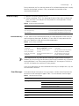
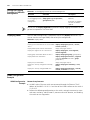
Table 2 Text conventions
Convention
Description
Screen
displays
This typeface represents text as it appears on the screen.
Keyboard key
names
If you must press two or more keys simultaneously, the key names are
linked with a plus sign (+), for example:
Press Ctrl+Alt+Del
The words “enter”
and “type”
When you see the word “enter” in this guide, you must type something,
and then press Return or Enter. Do not press Return or Enter when an
instruction simply says “type.”
Fixed command
text
This typeface indicates the fixed part of a command text. You must type
the command, or this part of the command, exactly as shown, and press
Return or Enter when you are ready to enter the command.
Example: The command display history-command must be
entered exactly as shown.
Variable
command text
This typeface indicates the variable part of a command text. You must
type a value here, and press Return or Enter when you are ready to enter
the command.
Example: in the command super level, a value in the range 0 to 3
must be entered in the position indicated by level
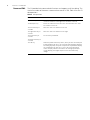
{x|y|…}
Alternative items, one of which must be entered, are grouped in braces
and separated by vertical bars. You must select and enter one of the
items.
Example: in the command flow-control {hardware | none |
software}, the braces and the vertical bars combined indicate that
you must enter one of the parameters. Enter either hardware, or
none, or software.
[ ]
Items shown in square brackets [ ] are optional.
Example 1: in the command display users [all], the square
brackets indicate that the parameter all is optional. You can enter the
command with or without this parameter.
Example 2: in the command user-interface [type]
first-number [last-number] the square brackets indicate that the
parameters [type] and [last-number] are both optional. You can
enter a value in place of one, both or neither of these parameters.
Alternative items, one of which can optionally be entered, are grouped
in square brackets and separated by vertical bars.
Example 3: in the command header [shell | incoming |
login] text, the square brackets indicate that the parameters
shell, incoming and login are all optional. The vertical bars
indicate that only one of the parameters is allowed.
Related Manuals
The 3Com Switch 4200 Family Getting Started Guide provides information about
installation.
The 3Com Switch 4200 Family Command Reference Guide provides all the
information you need to use the configuration commands.
4
ABOUT THIS GUIDE
1
Introduction to the CLI
Command
Level/Command View
CLI OVERVIEW
A S4200G series Ethernet switch provides a command line interface (CLI) and
commands for you to configure and manage the Ethernet switch. The CLI is featured
by the following:
■
Commands are grouped by levels. This prevents unauthorized users from
operating the switch with relevant commands.
■
Users can gain online help at any time by entering the question mark “?”.
■
Commonly used diagnosing utilities (such as Tracert and Ping) are available.
■
Debugging information of various kinds is available.
■
The command history is available. You can recall and execute a history command
easily.
■
You can execute a command by only entering part of the command in the CLI, as
long as the keywords you input uniquely identify the corresponding ones.
To prevent unauthorized accesses, commands are grouped by command levels.
Commands fall into four levels: visit, monitor, system, and manage:
■
Visit level: Commands at this level are mainly used to diagnose network and
change the language mode of user interface, and cannot be saved in
configuration files. For example, the ping, tracert, and language-mode
commands are at this level.
■
Monitor level: Commands at this level are mainly used to maintain the system and
diagnose service problems, and cannot be saved to configuration files. For
example, the display and debugging commands are at this level.
■
System level: Commands at this level are mainly used to configure services.
Commands concerning routing and network layers are at this level. You can utilize
network services by using these commands.
■
Manage level: Commands at this level are associated with the basic operation of
the system, and the system supporting modules. These commands provide
supports to services. Commands concerning file system, FTP/TFTP/XModem
downloading, user management, and level setting are at this level.
Users logging into a switch also fall into four levels, each of which corresponding to
one of the above command levels. Users at a specific level can only use the
commands of the same level and those of the lower levels.
Switching between
User Levels
A user can switch the user level from one to another by executing a related command
after logging into a switch. The administrator can also set user level switching
passwords so that users can switch their levels from lower ones to higher ones only
when they input the correct passwords.
2
CHAPTER 1: CLI OVERVIEW
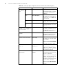
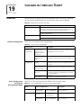
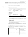
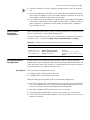
Setting a user level switching password
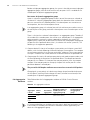
Table 1 lists the operations to set a user level switching password.
Table 1 Set a user level switching password
Operation
Command
Description
Enter system view
system-view
—
Set a password for
super password [ level level ]
switching from a lower { simple | cipher } password
user level to the user
level identified by the
level argument
Optional
A password is necessary only when
a user switches from a lower user
level to a higher user level.
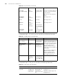
Switching to another user level
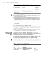
Table 2 lists operations to switch to another user level.
Table 2 Switch to another user level
Operation
Command
Switch to the user level super [ level ]
identified by the level
argument
Description
Required
Execute this command in user view.
If a password for switching to the
user level identified by the level
argument is set and you want to
switch to a lower user level, you will
remain at the lower user level unless
you provide the correct password
after executing this command.
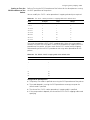
For security purpose, the password a user enters when switching to a higher user level
is not displayed. A user will remain at the original user level if the user has tried three
times to enter the correct password but fails to do this.
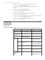
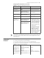
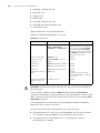
Configuring the Level of
a Specific Command in a
Specific View
You can configure the level of a specific command in a specific view. Commands fall
into four command levels: visit, monitor, system, and manage, which are identified as
0, 1, 2, and 3 respectively. The administrator can change the command level a
command belongs to.
Table 3 lists the operations to configure the level of a specific command.
Table 3 Configure the level of a specific command in a specific view
Operation
Command
Description
Enter system view
system-view
—
Configure the level of a command-privilege level level
specific command in a view view command
specific view
CLI Views
Required
Use this command with caution to
prevent inconvenience on
maintenance and operation.
CLI views are designed for different configuration tasks. They are interrelated. You will
enter user view once you log into a switch successfully, where you can perform
operations such as displaying operation status and statistical information. And by
executing the system-view command, you can enter system view, where you can
enter other views by executing the corresponding commands.
The following CLI views are provided:
■
User view
Command Level/Command View
■
System view
■
Ethernet port view
■
VLAN view
■
VLAN interface view
■
LoopBack interface view
■
Local user view
■
User interface view
■
FTP client view
■
SFTP client view
■
MST region view
■
Cluster view
■
Public key view
■
Public key editing view
■
Basic ACL view
■
Advanced ACL view
■
Layer 2 ACL view
■
RADIUS scheme view
■
ISP domain view
3
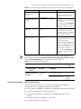
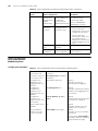
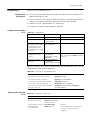
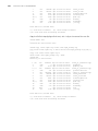
Table 4 lists information about CLI views (including the operations you can performed
in these views, how to enter these views, and so on).
Table 4 CLI views
View
User view
Available
operation
Prompt
example
Display operation
status and
statistical
information
System view Configure system
parameters
Ethernet
port view
Enter method
Quit method
<S4200G>
Enter user view once
logging into the
switch.
Execute the quit
command in user
view to log out of
the switch.
[4200G]
Execute the
system-view
command in user
view.
Execute the quit or
return command
to return to user
view.
Configure Ethernet [4200G-GigabitEt Execute the interface
port parameters
hernet1/0/1]
gigabitethernet
1/0/1 command in
system view.
Execute the quit
command to
return to system
view.
Execute the return
command to
return to user
view.
[4200G-TenGiga
bitEthernet1/1/1]
Execute the interface
tengigabitethernet
1/1/1 command in
system view.
4
CHAPTER 1: CLI OVERVIEW
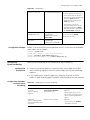
Table 4 CLI views (Continued)
View
VLAN view
Available
operation
Prompt
example
Configure VLAN
parameters
[4200G-Vlan1]
Enter method
Quit method
Execute the vlan 1
command in system
view.
Execute the quit
command to
return to system
view.
Execute the return
command to
return to user
view.
VLAN
interface
view
LoopBack
interface
view
Configure IP
[4200G-Vlan-inte Execute the interface
interface
rface1]
vlan-interface 1
parameters for
command in system
VLANs and
view.
aggregated VLANs
Execute the quit
command to
return to system
view.
Configure
[4200G-LoopBac
LoopBack interface k0]
parameters
Execute the quit
command to
return to system
view.
Execute the interface
loopback 0
command in system
view
Execute the return
command to
return to user
view.
Execute the return
command to
return to user
view.
Local user
view
Configure local
user parameters
[4200G-luser-use Execute the
r1]
local-user user1
command in system
view.
Execute the quit
command to
return to system
view.
Execute the return
command to
return to user
view.
User
interface
view
Configure user
interface
parameters
[4200G-ui0]
Execute the
user-interface 0
command in system
view.
Execute the quit
command to
return to system
view.
Execute the return
command to
return to user
view.
FTP client
view
Configure FTP
client parameters
[ ftp]
Execute the ftp
command in user
view.
Execute the quit
command to
return to user
view.
SFTP client
view
Configure SFTP
client parameters
<sftp-client>
Execute the sftp
Execute the quit
10.1.1.1 command in command to
system view.
return to user
view.
MST region
view
Configure MST
region parameters
[4200G-mst-regi
on]
Execute the stp
region-configuratio
n command in system
view.
Execute the quit
command to
return to system
view.
Execute the return
command to
return to user
view.
Command Level/Command View
5
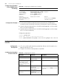
Table 4 CLI views (Continued)
View
Available
operation
Cluster view Configure cluster
parameters
Prompt
example
[4200G-cluster]
Enter method
Quit method
Execute the cluster
command in system
view.
Execute the quit
command to
return to system
view.
Execute the return
command to
return to user
view.
Public key
view
Configure RSA
[4200G-rsa-publi
public keys for SSH c-key]
users
Public key
editing view
Edit RSA public
keys of SSH users
Basic ACL
view
Define rules for a [4200G-aclbasic ACL (ACLs
basic-2000]
with their IDs
ranging from 2000
to 2999 are basic
ACLs.)
Execute the acl
number 2000
command in system
view.
Define rules for an [4200G-acladvanced ACL
adv-3000]
(ACLs with their
IDs ranging from
3000 to 3999 are
advanced ACLs.)
Execute the acl
number 3000
command in system
view.
Advanced
ACL view
Layer 2 ACL
view
Define the
sub-rules of Layer
2 ACLs, which is
numbered from
4000 to 4999.
Execute the rsa
peer-public-key
S4200G003
command in system
view.
Execute the
peer-public-key
end command to
return to system
view.
[4200G-rsa-key-c Execute the
ode]
public-key-code
begin command in
public key view.
Execute the
public-key-code
end command to
return to public
key view.
Execute the quit
command to
return to system
view.
Execute the return
command to
return to user
view.
Execute the quit
command to
return to system
view.
Execute the return
command to
return to user
view.
[4200G-acl-ether Execute the acl
netframe-4000]
number 4000
command in system
view.
Execute the quit
command to
return to system
view.
Execute the return
command to
return to user
view.
RADIUS
Configure RADIUS [4200G-radius-1] Execute the radius
scheme view parameters
scheme 1 command
in system view.
Execute the quit
command to
return to system
view.
Execute the return
command to
return to user
view.
ISP domain
view
Configure
parameters for an
ISP domain
[4200G-isp-3Co
m163.net]
Execute the domain
3Com163.net
command in system
view.
Execute the quit
command to
return to system
view.
Execute the return
command to
return to user
view.
6
CHAPTER 1: CLI OVERVIEW
CLI Features
Online Help
CLI provides two types of online help: complete online help and partial online help.
They assist you with your configuration.
Complete online help
Enter a “?” character in any view on your terminal to display all the commands
available in the view and their brief descriptions. The following takes user view as an
example.
<S4200G> ?
User view commands:
boot
Set boot option
cd
Change the current path
clock
Specify the system clock
cluster
Run cluster command
copy
Copy the file
debugging
Enable system debugging functions
delete
Delete the file
dir
Display the file list in system
display
Display current system information
<omitted>
Enter a command, a space, and a “?” character (instead of a keyword available in this
position of the command) on your terminal to display all the available keywords and
their brief descriptions. The following takes the clock command as an example.
<S4200G> clock
datetime
summer-time
timezone
?
Specify the time and date
Configure summer time
Configure time zone
Enter a command, a space, and a “?” character (instead of an argument available in
this position of the command) on your terminal to display all the available arguments
and their brief descriptions. The following takes the interface vlan command as an
example.
[4200G] interface vlan ?
<1-4094> VLAN interface number
[4200G] interface vlan 1 ?
<cr>
The string <cr> means no argument is available in the position occupied by the “?”
character. You can execute the command without providing any other information.
Partial online help
Enter a string followed directly by a “?” character on your terminal to display all the
commands beginning with the string. For example:
<S4200G> pi?
ping
Enter a command, a space, and a string followed by a “?” character on your terminal
to display all the keywords that belong to the command and begin with the string (if
available). For example:
<S4200G> display ver?
version
Terminal Display
7
Enter a command, the first several characters of an available keyword which uniquely
identifies the keyword, and press <Tab>, to complete the keyword will be
automatically completed.
Terminal Display
CLI provides the following display feature:
■
Display suspending. That is, the displaying of output information can be paused
when the screen is full and you can then perform the three operations listed in
Table 5 as needed.
Table 5 Displaying-related operations
Command History
Operation
Function
Press <Ctrl+C>
Suspend displaying and executing.
Press the space key
Scroll the output information up by one page.
Press <Enter>
Scroll the output information up by one line.
CLI can store the latest executed commands as history commands so that users can
recall and execute them again. By default, CLI can store 10 history commands for
each user. Table 6lists history command-related operations.
Table 6 Access history commands
Operation
Operation
Description
Display history
commands
Execute the display
history-command command
This command displays valid history
commands.
Recall the previous
history command
Press the up-arrow key or
<Ctrl+P>
This operation recalls the previous
history command (if available).
Recall the next history
command
Pressing the down-arrow key or
<Ctrl+N>
This operation recalls the next
history command (if available).
As the Up and Down keys have different meanings in HyperTerminal running on
Windows 9x, these two keys can be used to recall history commands only in terminals
running Windows 3.x or Telnet running in Windows 3.x. You can press <Ctrl+P> or
<Ctrl+N> in Windows 9x to achieve the same purpose.
If you enter and execute the same command successively for multiple times, only the
first command is buffered.
Error Messages
If the command you enter passes the syntax check, it will be successfully executed;
otherwise an error message will appear. Table 7 lists the common error messages.
Table 7 Common error messages
Error message
Description
Unrecognized command
The command does not exist.
The keyword does not exist.
The parameter type is wrong.
The parameter value is out of range.
Incomplete command
The command entered is incomplete.
Too many parameters
You have entered too many parameters.
Ambiguous command
The parameters entered are ambiguous.
Wrong parameter found at '^'
position.
The parameter labeled by '^' is unrecognizable.
8
CHAPTER 1: CLI OVERVIEW
Command Edit
The CLI provides basic command edit functions and supports multi-line editing. The
maximum number of characters a command can contain is 256. Table 8 lists the CLI
edit operations.
Table 8 Edit operations
Press…
To…
A common key
Insert the character the key represents at the cursor and move the
cursor one character to the right if the edit buffer is not full.
The Backspace key
Delete the character on the left of the cursor and move the cursor
one character to the left.
The left arrow key or
<Ctrl+B>
Move the cursor one character to the left.
The right arrow key or
<Ctrl+F>
Move the cursor one character to the right.
The up arrow key or
<Ctrl+P>
Access history commands.
The down arrow key or
<Ctrl+N>
The Tab key
Utilize the partial online help. That is, when you enter an incomplete
keyword and the Tab key, if the entered keyword uniquely identifies
an existing keyword, the system completes the keyword and displays
the command on the next line, or else (if the entered keyword
neither uniquely identifies nor matches an existing keyword) the
system displays your original input on a new line without any
change.
2
Logging into an
Ethernet Switch
LOGGING INTO AN ETHERNET SWITCH
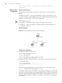
You can log into an S4200-G series Ethernet switch in one of the following ways:
■
Logging in locally through the Console port
■
Telneting locally or remotely to an Ethernet port
■
Telneting to the Console port using a modem
■
Logging into the Web-based network management system
■
Logging in through NMS (network management system)
Introduction to the
User Interface
Supported User
Interfaces
S4200-G series Ethernet switch supports two types of user interfaces: AUX and VTY.
Table 9 Description on user interface
User interface
Applicable user
Port used
Description
AUX
Users logging in
through the Console
port
Console port
Each switch can
accommodate one AUX user.
VTY
Telnet users and SSH
users
Ethernet port
Each switch can
accommodate up to five VTY
users.
As the AUX port and the Console port of a S4200G series switch are the same one,
you will be in the AUX user interface if you log in through this port.
User Interface Number
Two kinds of user interface index exist: absolute user interface index and relative user
interface index.
1 The absolute user interface indexes are as follows:
■
AUX user interface: 0
■
VTY user interfaces: Numbered after AUX user interfaces and increases in the step
of 1
2 A relative user interface index can be obtained by appending a number to the
identifier of a user interface type. It is generated by user interface type. The relative
user interface indexes are as follows:
■
AUX user interface: AUX 0
■
VTY user interfaces: VTY 0, VTY 1, VTY 2, and so on.
10
CHAPTER 2: LOGGING INTO AN ETHERNET SWITCH
Common User Interface
Configuration
Table 10 Common user interface configuration
Operation
Command
Description
Lock the current user
interface
lock
Optional
Execute this command in user view.
A user interface is not locked by
default.
Specify to send messages
to all user interfaces/a
specified user interface
send { all | number | type
number }
Optional
Execute this command in user view.
Disconnect a specified user free user-interface [ type ]
interface
number
Optional
Execute this command in user view.
Enter system view
system-view
—
Enter user interface view
user-interface [ type ]
first-number [ last-number ]
—
Set the command that is
automatically executed
when a user logs into the
user interface
auto-execute command
text
Optional
By default, no command is
automatically executed when a user
logs into a user interface.
Display the information
about the current user
interface/all user interfaces
display users [ all ]
You can execute this command in
any view.
Display the physical
attributes and
configuration of the
current/a specified user
interface
display user-interface [
type number | number ]
You can execute this command in
any view.
CAUTION:
■
The auto-execute command command may cause you unable to perform
common configuration in the user interface, so use it with caution.
■
Before executing the auto-execute command command and save your
configuration, make sure you can log into the switch in other modes and cancel
the configuration.
3
Introduction
LOGGING IN THROUGH THE CONSOLE
PORT
To log in through the Console port is the most common way to log into a switch. It is
also the prerequisite to configure other login methods. By default, you can log into an
S4200G series Ethernet switch through its Console port only.
To log into an Ethernet switch through its Console port, the related configuration of
the user terminal must be in accordance with that of the Console port.
Table 11 lists the default settings of a Console port.
Table 11 The default settings of a Console port
Setting
Default
Baud rate
9,600 bps
Flow control
Off
Check mode
No check bit
Stop bits
1
Data bits
8
After logging into a switch, you can perform configuration for AUX users. Refer to
“Console Port Login Configuration” for more.
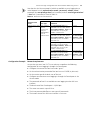
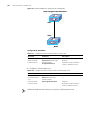
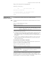
Setting up the
Connection to the
Console Port
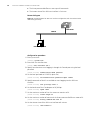
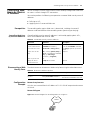
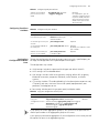
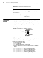
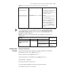
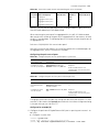
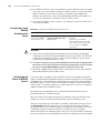
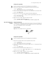
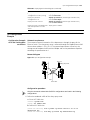
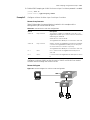
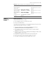
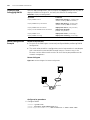
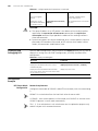
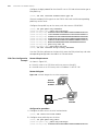
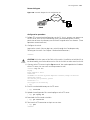
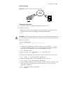
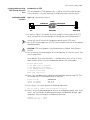
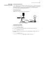
■
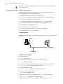
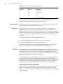
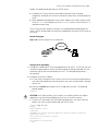
Connect the serial port of your PC/terminal to the Console port of the switch, as
shown in Figure 1.
Figure 1 Diagram for setting the connection to the Console port
RS-232 port
Console port
Configuration cable
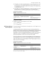
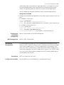
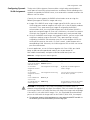
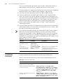
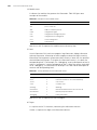
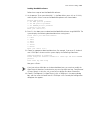
■
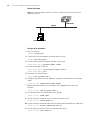
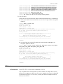
If you use a PC to connect to the Console port, launch a terminal emulation utility
(such as Terminal in Windows 3.X or HyperTerminal in Windows 9X) and perform
the configuration shown in Figure 2 through Figure 4 for the connection to be
created. Normally, the parameters of a terminal are configured as those listed in
Table 11. And the type of the terminal is set to VT100.
12
CHAPTER 3: LOGGING IN THROUGH THE CONSOLE PORT
Figure 2 Create a connection
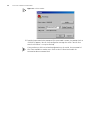
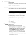
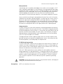
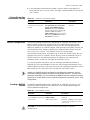
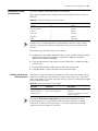
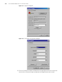
Figure 3 Specify the port used to establish the connection
Console Port Login Configuration
13
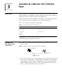
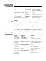
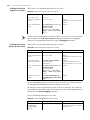
Figure 4 Set port parameters
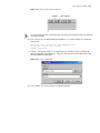
■
Turn on the switch. The user will be prompted to press the Enter key if the switch
successfully completes POST (power-on self test). The prompt (such as <S4200G>)
appears after the user presses the Enter key.
■
You can then configure the switch or check the information about the switch by
executing commands. You can also acquire help by type the ? character.
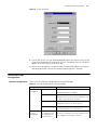
Console Port Login
Configuration
Common Configuration
Table 12 lists the common configuration of Console port login.
Table 12 Common configuration of Console port login
Configuration
Console port
configuration
Description
Baud rate
Optional
The default baud rate is 9,600 bps.
Check mode
Optional
By default, the check mode of the Console port is set
to “none”, which means no check bit.
Stop bits
Optional
The default stop bits of a Console port is 1.
Data bits
Optional
The default data bits of a Console port is 8.
AUX user
interface
configuration
Configure the command Optional
level available to the
By default, commands of level 3 are available to the
users logging into the
users logging into the AUX user interface.
AUX user interface
14
CHAPTER 3: LOGGING IN THROUGH THE CONSOLE PORT
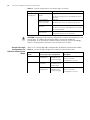
Table 12 Common configuration of Console port login (Continued)
Configuration
Terminal
configuration
Description
Make terminal services
available
Optional
Set the maximum
number of lines the
screen can contain
Optional
Set history command
buffer size
Optional
Set the timeout time of
a user interface
Optional
By default, terminal services are available in all user
interfaces
By default, the screen can contain up to 24 lines.
By default, the history command buffer can contain
up to 10 commands.
The default timeout time is 10 minutes.
CAUTION: Changing of Console port configuration terminates the connection to the
Console port. To establish the connection again, you need to modify the
configuration of the termination emulation utility running on your PC accordingly.
Refer to “Setting up the Connection to the Console Port” for more.
Console Port Login
Configurations for
Different Authentication
Modes
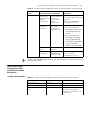
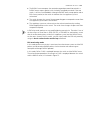
Table 13 lists Console port login configurations for different authentication modes.
Table 13 Console port login configurations for different authentication modes
Authentication
mode
None
Password
Console port login configuration
Description
Perform common Perform common
configuration
configuration for
Console port login
Optional
Configure the
password
Configure the
password for local
authentication
Required
Perform common Perform common
configuration
configuration for
Console port login
Optional
Refer to “Common
Configuration” for more.
Refer to “Common
Configuration” for more.
Console Port Login Configuration with Authentication Mode Being None
15
Table 13 Console port login configurations for different authentication modes (Continued)
Authentication
mode
Scheme
Console port login configuration
Description
Specify to
perform local
authentication or
RADIUS
authentication
AAA configuration
specifies whether to
perform local
authentication or
RADIUS
authentication
Optional
Configure user
name and
password
Configure user
names and
passwords for
local/remote users
Required
Manage AUX
users
Local authentication is performed
by default.
Refer to the “AAA&RADIUS
Configuration” for more.
■
The user name and
password of a local user
are configured on the
switch.
■
The user name and
password of a remote
user are configured on
the RADIUS server. Refer
to user manual of
RADIUS server for more.
Set service type for
AUX users
Required
Perform common Perform common
configuration
configuration for
Console port login
Optional
Refer to “Common
Configuration” for more.
Changes of the authentication mode of Console port login will not take effect unless
you restart the switch.
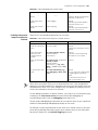
Console Port Login
Configuration with
Authentication Mode
Being None
Configuration Procedure
Table 14 Console port login configuration with the authentication mode being none
Operation
Command
Description
Enter system view
system-view
—
Enter AUX user interface view user-interface aux 0
—
Configure not to authenticate authentication-mode none
users
Required
By default, users logging in
through the Console port are not
authenticated.
16
CHAPTER 3: LOGGING IN THROUGH THE CONSOLE PORT
Table 14 Console port login configuration with the authentication mode being none
Operation
Configure
the Console
port
Command
Description
Set the baud
rate
speed speed-value
Optional
Set the check
mode
parity { even | mark |
none | odd | space }
Optional
Set the stop
bits
stopbits { 1 | 1.5 | 2 }
Optional
Set the data
bits
databits { 7 | 8 }
The default baud rate of an AUX
port (also the Console port) is
9,600 bps.
By default, the check mode of a
Console port is set to none, that
is, no check bit.
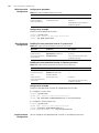
The stop bits of a Console port is 1.
Optional
The default data bits of a Console
port is 8.
Configure the command level user privilege level level
available to users logging into
the user interface
Optional
Make terminal services
available
shell
Optional
Set the maximum number of
lines the screen can contain
screen-length
screen-length
By default, commands of level 3
are available to users logging into
the AUX user interface.
By default, terminal services are
available in all user interfaces.
Optional
By default, the screen can contain
up to 24 lines.
You can use the screen-length 0
command to disable the function
to display information in pages.
Set the history command
buffer size
history-command
max-size value
Optional
Set the timeout time for the
user interface
idle-timeout minutes [
seconds ]
Optional
The default history command
buffer size is 10. That is, a history
command buffer can store up to
10 commands by default.
The default timeout time of a user
interface is 10 minutes.
With the timeout time being 10
minutes, the connection to a user
interface is terminated if no
operation is performed in the user
interface within 10 minutes.
You can use the idle-timeout 0
command to disable the timeout
function.
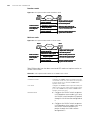
Console Port Login Configuration with Authentication Mode Being None
17
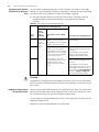
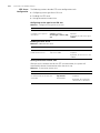
Note that the command level available to users logging into a switch depends on
both the authentication-mode { password | scheme | none } command and the
user privilege level level command, as listed in Table 15.
Table 15 Determine the command level (A)
Scenario
Authentication mode
User type
Command
Command level
None
(authentication-mode
none)
Users logging in The user privilege level
through Console level command not
ports
executed
The user privilege level
level command already
executed
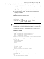
Configuration Example
Level 3
Determined by
the level
argument
Network requirements
Assume that you are a level 3 VTY user and want to perform the following
configuration for users logging in through the Console port:
■
Do not authenticate users logging in through the Console port.
■
Commands of level 2 are available to users logging into the AUX user interface.
■
The baud rate of the Console port is 19,200 bps.
■
The screen can contain up to 30 lines.
■
The history command buffer can contain up to 20 commands.
■
The timeout time of the AUX user interface is 6 minutes.
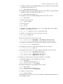
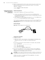
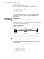
Network diagram
Figure 5 Network diagram for AUX user interface configuration (with the authentication
mode being none)
Ethernet1/0/1
Ethernet
User PC running Telnet
Configuration procedure
1 Enter system view.
<S4200G> system-view
2 Enter AUX user interface view.
[4200G] user-interface aux 0
18
CHAPTER 3: LOGGING IN THROUGH THE CONSOLE PORT
3 Specify not to authenticate users logging in through the Console port.
[4200G-ui-aux0] authentication-mode none
4 Specify commands of level 2 are available to users logging into the AUX user
interface.
[4200G-ui-aux0] user privilege level 2
5 Set the baud rate of the Console port to 19,200 bps.
[4200G-ui-aux0] speed 19200
6 Set the maximum number of lines the screen can contain to 30.
[4200G-ui-aux0] screen-length 30
7 Set the maximum number of commands the history command buffer can store to 20.
[4200G-ui-aux0] history-command max-size 20
8 Set the timeout time of the AUX user interface to 6 minutes.
[4200G-ui-aux0] idle-timeout 6
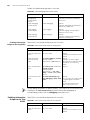
Console Port Login
Configuration with
Authentication Mode
Being Password
Configuration Procedure
Table 16 Console port login configuration with the authentication mode being password
Operation
Command
Description
Enter system view
system-view
—
Enter AUX user interface
view
user-interface aux 0
—
Configure to authenticate authentication-mode password
users using the local
password
Required
Set the local password
set authentication password
{ cipher | simple } password
Required
Configure
Set the
the Console baud rate
port
speed speed-value
Optional
The default baud rate of an AUX
port (also the Console port) is
9,600 bps.
Set the
parity { even | mark | none |
check mode odd | space }
Optional
Set the stop stopbits { 1 | 1.5 | 2 }
bits
Optional
Set the data databits { 7 | 8 }
bits
Optional
Configure the command
level available to users
logging into the user
interface
user privilege level level
By default, the check mode of a
Console port is set to none, that
is, no check bit.
The default stop bits of a Console
port is 1.
The default data bits of a Console
port is 8.
Optional
By default, commands of level 3
are available to users logging into
the AUX user interface.
Console Port Login Configuration with Authentication Mode Being Password
19
Table 16 Console port login configuration with the authentication mode being password
Operation
Command
Description
Make terminal services
available to the user
interface
shell
Optional
By default, terminal services are
available in all user interfaces.
Set the maximum number screen-length screen-length
of lines the screen can
contain
Optional
By default, the screen can contain
up to 24 lines.
You can use the screen-length 0
command to disable the function
to display information in pages.
Set history command
buffer size
history-command max-size
value
Optional
Set the timeout time for
the user interface
idle-timeout minutes [
seconds ]
Optional
The default history command
buffer size is 10. That is, a history
command buffer can store up to
10 commands by default.
The default timeout time of a user
interface is 10 minutes.
With the timeout time being 10
minutes, the connection to a user
interface is terminated if no
operation is performed in the user
interface within 10 minutes.
You can use the idle-timeout 0
command to disable the timeout
function.
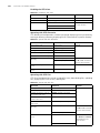
Note that the level the commands of which are available to users logging into a
switch depends on both the authentication-mode { password | scheme | none }
and the user privilege level level command, as listed in Table 17.
Table 17 Determine the command level (B)
Scenario
Authentication
mode
User type
Local authentication
Users logging into
(authentication-mode the AUX user
password)
interface
Configuration Example
Command
level
Command
The user privilege level level Level 3
command not executed
The user privilege level level Determined by
command already executed
the level
argument
Network requirements
Assume that you are a level 3 VTY user and want to perform the following
configuration for users logging in through the Console port:
■
Authenticate users logging in through the Console port using the local password.
■
Set the local password to 123456 (in plain text).
■
The commands of level 2 are available to users logging into the AUX user
interface.
■
The baud rate of the Console port is 19,200 bps.
■
The screen can contain up to 30 lines.
20
CHAPTER 3: LOGGING IN THROUGH THE CONSOLE PORT
■
The history command buffer can store up to 20 commands.
■
The timeout time of the AUX user interface is 6 minutes.
Network diagram
Figure 6 Network diagram for AUX user interface configuration (with the authentication
mode being password)
Ethernet1/0/1
Ethernet
User PC running Telnet
Configuration procedure
1 Enter system view.
<S4200G> system-view
2 Enter AUX user interface view.
[4200G] user-interface aux 0
3 Specify to authenticate users logging in through the Console port using the local
password.
[4200G-ui-aux0] authentication-mode password
4 Set the local password to 123456 (in plain text).
[4200G-ui-aux0] set authentication password simple 123456
5 Specify commands of level 2 are available to users logging into the AUX user
interface.
[4200G-ui-aux0] user privilege level 2
6 Set the baud rate of the Console port to 19,200 bps.
[4200G-ui-aux0] speed 19200
7 Set the maximum number of lines the screen can contain to 30.
[4200G-ui-aux0] screen-length 30
8 Set the maximum number of commands the history command buffer can store to 20.
[4200G-ui-aux0] history-command max-size 20
9 Set the timeout time of the AUX user interface to 6 minutes.
[4200G-ui-aux0] idle-timeout 6
Console Port Login Configuration with Authentication Mode Being Scheme
21
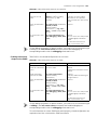
Console Port Login
Configuration with
Authentication Mode
Being Scheme
Configuration Procedure
Table 18 Console port login configuration with authentication mode being scheme
Operation
Command
Description
Enter system view
system-view
—
Configure
the
authentic
ation
mode
Enter the
default ISP
domain view
domain system
Optional
Specify the
AAA scheme
to be applied
to the domain
scheme { local |
radius-scheme
radius-scheme-name [
local ] | none }
Quit to system quit
view
Create a local user (Enter
local user view.)
local-user user-name
By default, the local AAA scheme is
applied. If you specify to apply the local
AAA scheme, you need to perform the
configuration concerning local user as
well.
If you specify to apply an existing
scheme by providing the
radius-scheme-name argument, you
need to perform the following
configuration as well:
■
Perform AAA&RADIUS
configuration on the switch. (Refer
to “AAA&RADIUS Configuration”
for more.)
■
Configure the user name and
password accordingly on the AAA
server. (Refer to the user manual of
AAA server.)
Required
No local user exists by default.
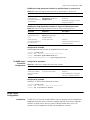
Set the authentication
password { simple |
password for the local user cipher } password
Required
Specify the service type for service-type terminal [
AUX users
level level ]
Required
Quit to system view
quit
—
Enter AUX user interface
view
user-interface aux 0
—
Configure to authenticate
users locally or remotely
authentication-mode
scheme
Required
The specified AAA scheme determines
whether to authenticate users locally or
remotely.
Users are authenticated locally by
default.
22
CHAPTER 3: LOGGING IN THROUGH THE CONSOLE PORT
Table 18 Console port login configuration with authentication mode being scheme
Operation
Configure
the Console
port
Set the
baud rate
Command
Description
speed speed-value
Optional
The default baud rate of the AUX port
(also the Console port) is 9,600 bps.
Set the
parity { even | mark |
check mode none | odd | space }
Optional
Set the stop stopbits { 1 | 1.5 | 2 }
bits
Optional
Set the data databits { 7 | 8 }
bits
Optional
Configure the command
level available to users
logging into the user
interface
user privilege level level
Make terminal services
available to the user
interface
shell
Set the maximum number
of lines the screen can
contain
screen-length
screen-length
By default, the check mode of a
Console port is set to none, that is, no
check bit.
The default stop bits of a Console port
is 1.
The default data bits of a Console port
is 8.
Optional
By default, commands of level 3 are
available to users logging into the AUX
user interface.
Optional
By default, terminal services are
available in all user interfaces.
Optional
By default, the screen can contain up to
24 lines.
You can use the screen-length 0
command to disable the function to
display information in pages.
Set history command
buffer size
history-command
max-size value
Optional
Set the timeout time for
the user interface
idle-timeout minutes [
seconds ]
Optional
The default history command buffer
size is 10. That is, a history command
buffer can store up to 10 commands by
default.
The default timeout time of a user
interface is 10 minutes.
With the timeout time being 10
minutes, the connection to a user
interface is terminated if no operation is
performed in the user interface within
10 minutes.
You can use the idle-timeout 0
command to disable the timeout
function.
Console Port Login Configuration with Authentication Mode Being Scheme
23
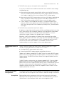
Note that the level the commands of which are available to users logging into a
switch depends on the authentication-mode { password | scheme | none }
command, the user privilege level level command, and the service-type terminal
[ level level ] command, as listed in Table 19.
Table 19 Determine the command level
Scenario
Authentication
mode
Command level
User type
authentication-mode Users logging
scheme
into the
Console port
and pass
AAA&RADIUS
or local
authentication
Command
The user privilege level level
Level 0
command is not executed, and the
service-type terminal [ level level ]
command does not specify the
available command level.
The user privilege level level
command is not executed, and the
service-type terminal [ level level ]
command specifies the available
command level.
Determined by
the service-type
terminal [ level
level ] command
The user privilege level level
Level 0
command is executed, and the
service-type terminal [ level level ]
command does not specify the
available command level.
The user privilege level level
command is executed, and the
service-type terminal [ level level ]
command specifies the available
command level.
Configuration Example
Determined by
the service-type
terminal [ level
level ] command
Network requirements
Assume that you are a level 3 VTY user and want to perform the following
configuration for users logging in through the Console port:
■
Configure the name of the local user to be “guest”.
■
Set the authentication password of the local user to 123456 (in plain text).
■
Set the service type of the local user to Terminal.
■
Configure to authenticate users logging in through the Console port in the
scheme mode.
■
The commands of level 2 are available to users logging into the AUX user
interface.
■
The baud rate of the Console port is 19,200 bps.
■
The screen can contain up to 30 lines.
■
The history command buffer can store up to 20 commands.
■
The timeout time of the AUX user interface is 6 minutes.
24
CHAPTER 3: LOGGING IN THROUGH THE CONSOLE PORT
Network diagram
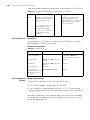
Figure 7 Network diagram for AUX user interface configuration (with the authentication
mode being scheme)
Ethernet1/0/1
Ethernet
User PC running Telnet
Configuration procedure
1 Enter system view.
<S4200G> system-view
2 Create a local user named guest and enter local user view.
[4200G] local-user guest
3 Set the authentication password to 123456 (in plain text).
[4200G-luser-guest] password simple 123456
4 Set the service type to Terminal.
[4200G-luser-guest] service-type terminal level 2
[4200G-luser-guest] quit
5 Enter AUX user interface view.
[4200G] user-interface aux 0
6 Configure to authenticate users logging in through the Console port in the scheme
mode.
[4200G-ui-aux0] authentication-mode scheme
7 Specify commands of level 2 are available to users logging into the AUX user
interface.
[4200G-ui-aux0] user privilege level 2
8 Set the baud rate of the Console port to 19,200 bps.
[4200G-ui-aux0] speed 19200
9 Set the maximum number of lines the screen can contain to 30.
[4200G-ui-aux0] screen-length 30
10 Set the maximum number of commands the history command buffer can store to 20.
[4200G-ui-aux0] history-command max-size 20
11 Set the timeout time of the AUX user interface to 6 minutes.
[4200G-ui-aux0] idle-timeout 6
4
Introduction
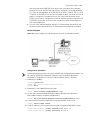
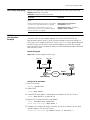
LOGGING IN USING MODEM
The administrator can log into the Console port of a remote switch using a modem
through PSTN (public switched telephone network) if the remote switch is connected
to the PSTN through a modem to configure and maintain the switch remotely. When
a network operates improperly or is inaccessible, you can log into the switches in the
network in this way to configure these switches, to query logs and warning
messages, and to locate problems.
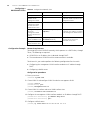
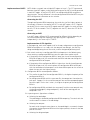
To log into a switch in this way, you need to configure the terminal and the switch
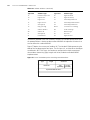
properly, as listed in Table 20.
Table 20 Requirements for logging into a switch using a modem
Item
Requirement
Administrator side
The PC can communicate with the modem connected to it.
The modem is properly connected to PSTN.
The telephone number of the switch side is available.
Switch side
The modem is connected to the Console port of the switch
properly.
The modem is properly configured.
The modem is properly connected to PSTN and a telephone set.
The authentication mode and other related settings are configured
on the switch. Refer to Table 76 in “Logging in through Telnet”.
Configuration on the
Administrator Side
The PC can communicate with the modem connected to it. The modem is properly
connected to PSTN. And the telephone number of the switch side is available.
Configuration on the
Switch Side
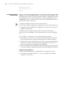
Modem Configuration
Perform the following configuration on the modem directly connected to the switch:
AT&F
----------------------- Restore the factory settings
ATS0=1----------------------- Configure to answer automatically after
the first ring
AT&D ----------------------- Ignore DTR signal
AT&K0----------------------- Disable flow control
AT&R1----------------------- Ignore RTS signal
AT&S0----------------------- Set DSR to high level by force
ATEQ1&W----------------------- Disable the modem from returning command
response and the result, save the changes
You can verify your configuration by executing the AT&V command.
The above configuration is unnecessary to the modem on the administrator side.The
configuration commands and the output of different modems may differ. Refer to the
user manual of the modem when performing the above configuration.
26
CHAPTER 4: LOGGING IN USING MODEM
Switch Configuration
After logging into a switch through its Console port by using a modem, you will enter
the AUX user interface. The corresponding configuration on the switch is the same as
those when logging into the switch locally through its Console port except that:
■
When you log in through the Console port using a modem, the baud rate of the
Console port is usually set to a value lower than the transmission speed of the
modem. Otherwise, packets may get lost.
■
Other settings of the Console port, such as the check mode, the stop bits, and the
data bits, remain the default.
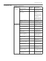
The configuration on the switch depends on the authentication mode the user is in.
Refer to Table 13 in Chapter 3 for the information about authentication mode
configuration.
Configuration on switch when the authentication mode is none
Refer to “Configuration on switch when the authentication mode is none”.
Configuration on switch when the authentication mode is password
Refer to “Configuration on switch when the authentication mode is password”.
Configuration on switch when the authentication mode is scheme
Refer to “Configuration on switch when the authentication mode is scheme”.
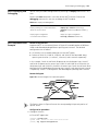
Modem Connection
Establishment
1 Configure the user name and password on the switch. Refer to “Console Port Login
Configuration with Authentication Mode Being None”, “Configuration on switch
when the authentication mode is password”, and “Configuration on switch when
the authentication mode is scheme” in Chapter 3 for more.
2 Perform the following configuration on the modem directly connected to the switch.
AT&F
----------------------- Restore the factory settings
ATS0=1----------------------- Configure to answer automatically after
the first ring
AT&D ----------------------- Ignore DTR signal
AT&K0----------------------- Disable flow control
AT&R1----------------------- Ignore RTS signal
AT&S0----------------------- Set DSR to high level by force
ATEQ1&W----------------------- Disable the modem from returning command
response and the result, save the changes
You can verify your configuration by executing the AT&V command.
The configuration commands and the output of different modems may differ. Refer
to the user manual of the modem when performing the above configuration.
It is recommended that the baud rate of the AUX port (also the Console port) be set
to a value lower than the transmission speed of the modem. Otherwise, packets may
get lost.
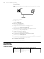
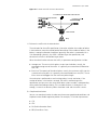
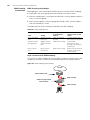
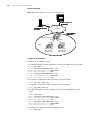
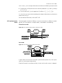
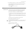
Modem Connection Establishment
27
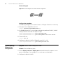
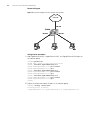
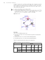
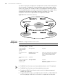
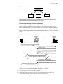
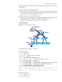
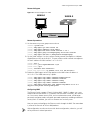
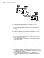
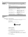
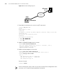
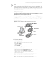
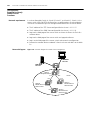
3 Connect your PC, the modems, and the switch, as shown in Figure 8.
Figure 8 Establish the connection by using modems
Serial cable
Modem
PC
Telephone line
PSTN
Modem
Console port
Telephone number: 82882285
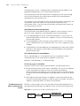
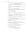
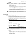
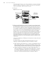
4 Launch a terminal emulation utility on the PC and set the telephone number to call
the modem directly connected to the switch, as shown in Figure 9 and Figure 10.
Note that you need to set the telephone number to that of the modem directly
connected to the switch.
Figure 9 Set the telephone number
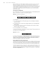
28
CHAPTER 4: LOGGING IN USING MODEM
Figure 10 Call the modem
5 Provide the password when prompted. If the password is correct, the prompt (such as
<S4200G>) appears. You can then configure or manage the switch. You can also
enter the character ? at anytime for help.
If you perform no AUX user-related configuration on the switch, the commands of
level 3 are available to modem users. Refer to the CLI Overview module for
information about command level.
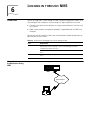
5
Introduction
LOGGING IN THROUGH WEB-BASED
NETWORK MANAGEMENT SYSTEM
An S4200-G series switch has a Web server built in. You can log into an S4200-G
series switch through a Web browser and manage and maintain the switch intuitively
by interacting with the built-in Web server.
To log into an S4200-G series switch through the built-in Web-based network
management system, you need to perform the related configuration on both the
switch and the PC operating as the network management terminal.
Table 21 Requirements for logging into a switch through the Web-based network
management system
Item
Requirement
Switch
The management VLAN of the switch is configured. The route
between the switch and the network management terminal is
available. (Refer to the Management VLAN Configuration module
for more.)
The user name and password for logging into the Web-based
network management system are configured.
PC operating as the
network management
terminal
IE is available.
The IP address of the management VLAN interface of the switch is
available.
HTTP Connection
Establishment
1 Log into the switch through the Console port and assign an IP address to the
management VLAN interface of the switch.
■
Connect to the Console port. To log into a switch through the Console port, you
need to connect the serial port of your PC (or terminal) to the Console port of the
switch using a configuration cable, as shown in Figure 11.
Figure 11 Connect to the Console port
(1)
( 2)
( 3)
Table 22 Callouts
(1) RS-232 port
(2) Console port
(3) Configuration cable
30
CHAPTER 5: LOGGING IN THROUGH WEB-BASED NETWORK MANAGEMENT SYSTEM
■
Launch a terminal emulation utility (such as Terminal in Windows 3.X or
HyperTerminal in Windows 9X) on the PC, with the baud rate set to 9,600 bps,
data bits set to 8, parity check set to off, and flow control set to off.
■
Turn on the switch. When the switch is starting, the information about self-testing
appears on the terminal window. When you press Enter after the self-testing
finishes, the prompt (such as <S4200G>) appears, as shown in the Figure 12.
Figure 12 The terminal window
■
Execute the following commands in the terminal window to assign an IP address
to the management VLAN interface of the switch.
<S4200G> system
a Enter management VLAN interface view.
[4200G] interface vlan-interface 1
b Remove the existing IP address of the management VLAN interface.
[4200G-VLAN-interface1] undo ip address
c Configure the IP address of the management VLAN interface to be 10.153.17.82.
[4200G-VLAN-interface1] ip address 10.153.17.82 255.255.255.0
2 Configure the user name and the password for the Web-based network management
system.
■
Add a Telnet user account for the switch, setting the user level to level 3 (the
administration level).
a Configure the user name to be admin.
[4200G] local-user admin
b Set the user level to level 3.
[4200G-luser-admin] service-type telnet level 3
c Set the password to admin.
[4200G-luser-admin] password simple admin
■
Configure a static route from the switch to the gateway.
[4200G] ip route-static ip-address 0.0.0.0 255.255.255.255
HTTP Connection Establishment
31
3 Establish an HTTP connection between your PC and the switch, as shown in
Figure 13.
Figure 13 Establish an HTTP connection between your PC and the switch
Sw itch
HTTP
Connection
connection
HTTP Connection
PC
PC
4 Log into the switch through IE. Launch IE on the Web-based network management
terminal (your PC) and enter the IP address of the management VLAN interface of the
switch (here it is http://10.153.17.82). (Make sure the route between the Web-based
network management terminal and the switch is available.)
5 When the login interface (shown in Figure 14) appears, enter the user name and the
password configured in step 2 and click <Login> to bring up the main page of the
Web-based network management system.
Figure 14 The login page of the Web-based network management system
32
CHAPTER 5: LOGGING IN THROUGH WEB-BASED NETWORK MANAGEMENT SYSTEM
6
Introduction
LOGGING IN THROUGH NMS
You can also log into a switch through an NMS (network management station), and
then configure and manage the switch through the agent module on the switch.
■
The agent here refers to the software running on network devices (switches) and
as the server.
■
SNMP (simple network management protocol) is applied between the NMS and
the agent.
To log into a switch through an NMS, you need to perform related configuration on
both the NMS and the switch.
Table 23 Requirements for logging into a switch through an NMS
Item
Requirement
Switch
The management VLAN of the switch is configured. The route between the
NMS and the switch is available. (Refer to the Management VLAN
Configuration module for more.)
The basic SNMP functions are configured. (Refer to the SNMP module for
more.)
NMS
Connection
Establishment Using
NMS
The NMS is properly configured. (Refer to the user manual of your NMS for
more.)
Figure 15 Network diagram for logging in through an NMS
Switch
HTTP Connection
PC
34
CHAPTER 6: LOGGING IN THROUGH NMS
CONTROLLING LOGIN USERS
7
Introduction
A switch provides ways to control different types of login users, as listed in Table 24.
Table 24 Ways to control different types of login users
Login mode Control method
Implementation
Related section
Telnet
By source IP addresses
Through basic ACLs
Controlling Telnet Users by
Source IP Addresses
By source and
destination IP addresses
Through advanced
ACLs
Controlling Telnet Users by
Source and Destination IP
Addresses
SNMP
By source IP addresses
Through basic ACLs
Controlling Network
Management Users by Source IP
Addresses
WEB
By source IP addresses
Through basic ACLs
Controlling Web Users by
Source IP Address.
Disconnect Web users by By executing
force
commands in CLI
Disconnecting a Web User by
Force.
Controlling Telnet
Users
Prerequisites
The controlling policy against Telnet users is determined, including the source and
destination IP addresses to be controlled and the controlling actions (permitting or
denying).
Controlling Telnet Users
by Source IP Addresses
Controlling Telnet users by source IP addresses is achieved by applying basic ACLs,
which are numbered from 2000 to 2999.
Table 25 Control Telnet users by source IP addresses
Operation
Command
Description
Enter system view
system-view
Create a basic ACL or
enter basic ACL view
acl number acl-number [
match-order { config | auto } ]
As for the acl number command,
the config keyword is specified by
default.
Define rules for the
ACL
rule [ rule-id ] { permit | deny } [
source { sour-addr sour-wildcard
| any } ] [ time-range
time-name ] [ fragment ]
Required
Quit to system view
quit
Enter user interface
view
user-interface [ type ]
first-number [ last-number ]
Apply the ACL to
control Telnet users by
source IP addresses
acl acl-number { inbound |
outbound }
Required
The inbound keyword specifies to
filter the users trying to Telnet to
the current switch.
The outbound keyword specifies
to filter users trying to Telnet to
other switches from the current
switch.
36
CHAPTER 7: CONTROLLING LOGIN USERS
Controlling Telnet Users
by Source and
Destination IP Addresses
Controlling Telnet users by source and destination IP addresses is achieved by applying
advanced ACLs, which are numbered from 3000 to 3999. Refer to the ACL module
for information about defining an ACL.
Table 26 Define an advanced ACL
Operation
Command
Enter system view
system-view
Description
Create an advanced
acl number acl-number [
ACL or enter advanced match-order { config | auto } ]
ACL view
As for the acl number command,
the config keyword is specified by
default.
Define rules for the
ACL
rule [ rule-id ] { permit | deny }
rule-string
Required
Quit to system view
quit
Enter user interface
view
user-interface [ type ]
first-number [ last-number ]
Apply the ACL to
control Telnet users by
specified source and
destination IP
addresses
acl acl-number { inbound |
outbound }
You can define rules as needed to
filter by specific source and
destination IP addresses.
Required
The inbound keyword specifies to
filter the users trying to Telnet to
the current switch.
The outbound keyword specifies
to filter users trying to Telnet to
other switches from the current
switch.
Configuration
Example
Network requirements
Only the Telnet users sourced from the IP address of 10.110.100.52 and
10.110.100.46 are permitted to log into the switch.
Network diagram
Figure 16 Network diagram for controlling Telnet users using ACLs
Internet
Sw itch
Configuration procedure
1 Define a basic ACL.
<S4200G> system-view
[4200G] acl number 2000 match-order config
[4200G-acl-basic-2000] rule 1 permit source 10.110.100.52 0
[4200G-acl-basic-2000] rule 2 permit source 10.110.100.46 0
[4200G-acl-basic-2000] rule 3 deny source any
[4200G-acl-basic-2000] quit
2 Apply the ACL.
[4200G] user-interface vty 0 4
[4200G-ui-vty0-4] acl 2000 inbound
Controlling Network Management Users by Source IP Addresses
Controlling
Network
Management
Users by Source
IP Addresses
Prerequisites
Controlling Network
Management Users
by Source IP
Addresses
37
You can manage a S4200G series Ethernet switch through network management
software. Network management users can access switches through SNMP.
You need to perform the following two operations to control network management
users by source IP addresses.
■
Defining an ACL
■
Applying the ACL to control users accessing the switch through SNMP
The controlling policy against network management users is determined, including
the source IP addresses to be controlled and the controlling actions (permitting or
denying).
Controlling network management users by source IP addresses is achieved by
applying basic ACLs, which are numbered from 2000 to 2999.
Table 27 Control network management users by source IP addresses
Operation
Command
Enter system view
system-view
Description
Create a basic ACL or
enter basic ACL view
acl number acl-number [
match-order { config | auto } ]
As for the acl number command,
the config keyword is specified by
default.
Define rules for the
ACL
rule [ rule-id ] { permit | deny } [
source { sour-addr sour-wildcard
| any } ] [ time-range
time-name ] [ fragment ]
Required
Quit to system view
quit
Apply the ACL while
configuring the SNMP
community name
snmp-agent community { read
| write } community-name [ [
mib-view view-name ] | [ acl
acl-number ] ]*
Optional
Apply the ACL while
configuring the SNMP
group name
snmp-agent group { v1 | v2c }
group-name [ read-view
read-view ] [ write-view
write-view ] [ notify-view
notify-view ] [ acl acl-number ]
Optional
snmp-agent group v3
group-name [ authentication |
privacy ] [ read-view
read-view ] [ write-view
write-view ] [ notify-view
notify-view ] [ acl acl-number ]
Apply the ACL while
configuring the SNMP
user name
snmp-agent usm-user { v1 |
v2c } user-name group-name [
acl acl-number ]
Optional
snmp-agent usm-user v3
user-name group-name [
authentication-mode { md5 |
sha } auth-password ] [
privacy-mode des56
priv-password ] [ acl acl-number ]
You can specify different ACLs while configuring the SNMP community name, the
SNMP group name and the SNMP user name.
38
CHAPTER 7: CONTROLLING LOGIN USERS
As SNMP community name is a feature of SNMP V1 and SNMP V2, the specified ACLs
in the command that configures SNMP community names (the snmp-agent
community command) take effect in the network management systems that adopt
SNMP V1 or SNMP V2.
Similarly, as SNMP group name and SNMP user name are features of SNMP V2 and
the higher SNMP versions, the specified ACLs in the commands that configure SNMP
group names (the snmp-agent group command and the snmp-agent group v3
command) and SNMP user names (the snmp-agent usm-user command and the
snmp-agent usm-user v3 command) take effect in the network management
systems that adopt SNMP V2 or higher SNMP versions. If you configure both the
SNMP group name and the SNMP user name and specify ACLs in the two operations,
the switch will filter network management users by both SNMP group name and
SNMP user name.
Configuration Example
Network requirements
Only SNMP users sourced from the IP addresses of 10.110.100.52 and 10.110.100.46
are permitted to access the switch.
Network diagram
Figure 17 Network diagram for controlling SNMP users using ACLs
Internet
Sw itch
Configuration procedure
1 Define a basic ACL.
<S4200G> system-view
[4200G] acl number 2000 match-order config
[4200G-acl-basic-2000] rule 1 permit source 10.110.100.52 0
[4200G-acl-basic-2000] rule 2 permit source 10.110.100.46 0
[4200G-acl-basic-2000] rule 3 deny source any
[4200G-acl-basic-2000] quit
2 Apply the ACL to only permit SNMP users sourced from the IP addresses of
10.110.100.52 and 10.110.100.46 to access the switch.
[4200G] snmp-agent community read 3Com acl 2000
[4200G] snmp-agent group v2c 3Comgroup acl 2000
[4200G] snmp-agent usm-user v2c 3Comuser 3Comgroup acl 2000
Controlling Web Users by Source IP Address
Controlling Web
Users by Source
IP Address
39
You can manage a S4200G series Ethernet switch remotely through Web. Web users
can access a switch through HTTP connections.
You need to perform the following two operations to control Web users by source IP
addresses.
Prerequisites
Controlling Web Users
by Source IP Addresses
■
Defining an ACL
■
Applying the ACL to control Web users
The controlling policy against Web users is determined, including the source IP
addresses to be controlled and the controlling actions (permitting or denying).
Controlling Web users by source IP addresses is achieved by applying basic ACLs,
which are numbered from 2000 to 2999.
Table 28 Control Web users by source IP addresses
Disconnecting a Web
User by Force
Operation
Command
Enter system view
system-view
Description
Create a basic ACL or
enter basic ACL view
acl number acl-number [
match-order { config | auto } ]
As for the acl number command,
the config keyword is specified by
default.
Define rules for the
ACL
rule [ rule-id ] { permit | deny } [
source { sour-addr sour-wildcard
| any } ] [ time-range
time-name ] [ fragment ]
Required
Quit to system view
quit
Apply the ACL to
control Web users
ip http acl acl-number
The administrator can disconnect a Web user by force using the related command.
Table 29 Disconnect a Web user by force
Operation
Command
Description
Disconnect a Web user free web-users { all | user-id
by force
userid | user-name username }
Configuration
Example
Optional
Required
Execute this command in user view.
Network requirements
Only the users sourced from the IP address of 10.110.100.46 are permitted to access
the switch.
Network diagram
Figure 18 Network diagram for controlling Web users using ACLs
Internet
Sw itch
40
CHAPTER 7: CONTROLLING LOGIN USERS
Configuration procedure
1 Define a basic ACL.
<S4200G> system-view
[4200G] acl number 2030 match-order config
[4200G-acl-basic-2030] rule 1 permit source 10.110.100.46 0
[4200G-acl-basic-2030] rule 2 deny source any
2 Apply the ACL to only permit the Web users sourced from the IP address of
10.110.100.46 to access the switch.
[4200G] ip http acl 2030
8
Introduction to
Configuration File
CONFIGURATION FILE MANAGEMENT
Configuration file records and stores user configurations performed to a switch. It
also enables users to check switch configurations easily.
Upon powered on, a switch loads the configuration file known as
saved-configuration file, which resides in the Flash, for initialization. If the Flash
contains no configuration file, the system initializes using the default settings.
Comparing to saved-configuration file, the configuration file which is currently
adopted by a switch is known as the current-configuration.
A configuration file conforms to the following conventions:
Configuration
File-Related
Configuration
■
The content of a configuration files is a series of commands.
■
Only the non-default configuration parameters are saved.
■
The commands are grouped into sections by command view. The commands that
are of the same command view are grouped into one section. Sections are
separated by empty lines or comment lines. (A line is a comment line if it starts
with the character “#”.)
■
The sections are listed in this order: system configuration section, physical port
configuration section, logical interface configuration section, routing protocol
configuration section, and so on.
■
A configuration file ends with a “return”.
You can perform the following operations on an S4200G series switch:
■
Saving the current configuration to a configuration file or erasing a configuration
file in the Flash
■
Checking/Setting the configuration file to be used when the switch starts the next
time
■
Setting a configuration file to be of the main/backup attribute
Perform the following configuration in user view.
Table 30 Configure a configuration file
Operation
Command
Description
Save the current
save [ cfgfile | [ safely ] [
configuration to a
backup | main ] ]
specified configuration
file and specify the
configuration file to be
of the main or backup
attribute
Optional
This command can be executed in
any view.
Erase the configuration reset saved-configuration [
file in the Flash
backup | main ]
Optional
Specify that the
Optional
undo startup
switch starts without saved-configuration [ unit
unit-id ]
loading the
configuration file
42
CHAPTER 8: CONFIGURATION FILE MANAGEMENT
Table 30 Configure a configuration file (Continued)
Operation
Command
Description
Specify the
startup saved-configuration
configuration file to be cfgfile [ backup | main ]
used when the switch
starts the next time
Optional
By default, the main configuration
file is used.
Check the
configuration file
display saved-configuration [
unit unit-id ] [ by-linenum ]
Check the current
configuration
display current-configuration [
configuration [
configuration-type ] | interface [
interface-type ] [
interface-number ] | vlan [
vlan-id ] ] [ by-linenum [ |
{ begin | include | exclude }
regular-expression ]
Optional
This command can be executed in
any view.
Display the
configuration
performed in the
current view
display this [ by-linenum ]
Display the information display startup [ unit unit-id ]
about the
configuration file to be
used for startup.
CAUTION: Currently, the extension of a configuration file is cfg. Configuration files
reside in the root directory.
9
VLAN CONFIGURATION
VLAN Overview
Introduction to VLAN
The virtual local area network (VLAN) technology is developed for switches to control
broadcast operations in LANs.
By creating VLANs in a physical LAN, you can divide the LAN into multiple logical
LANs, each of which has a broadcast domain of its own. Hosts in the same VLAN
communicate with each other as if they are in a LAN. However, hosts in different
VLANs cannot communicate with each other directly. Figure 19 illustrates a VLAN
implementation.
Figure 19 A VLAN implementation
VLAN A
LAN Switch
VLAN B
VLAN A
LAN Switch
VLAN A
VLAN B
VLAN B
Router
A VLAN can span across multiple switches, or even routers. This enables hosts in a
VLAN to be dispersed in a more loose way. That is, hosts in a VLAN can belong to
different physical network segment.
VLAN enjoys the following advantages.
1 Broadcasts are confined to VLANs. This decreases bandwidth utilization and improves
network performance.
2 Network security is improved. VLANs cannot communicate with each other directly.
That is, hosts in different VLANs cannot communicate with each other directly. To
enable communications between different VLANs, network devices operating on
Layer 3 (such as routers or Layer 3 switches) are needed.
3 Configuration workload is reduced. VLAN can be used to group specific hosts. When
the physical position of a host changes, no additional network configuration is
required if the host still belongs to the same VLAN.
VLAN standard is described in IEEE 802.1Q, which is issued by IEEE in 1999.
44
CHAPTER 9: VLAN CONFIGURATION
VLAN Classification
You can create port-based and policy-based VLAN types a Switch 4200G:
The port-based VLAN members are defined in terms of switch ports. You can add
ports to which close-related hosts are connected to the same port-based VLAN. This is
the simplest yet most effective way to create VLANs.
Policy-based VLANs enable a switch to forward received packets that match specific
QoS/ACLs to specific VLANs. For instructions on creating policy-based VLANs, see
“QoS Configuration” on page 213.
VLAN Configuration
Basic VLAN
Configuration
Configuring a
Port-Based VLAN
Table 31 Basic VLAN configuration
Operation
Command
Description
Enter system view
system-view
-
Create a VLAN and
enter VLAN view
vlan vlan-id
Required
Assign a name for the
VLAN
name
Specify the description
string of the VLAN
description string
The vlan-id argument ranges from 1
to 4094.
Optional
By default, the name of a VLAN is
its VLAN ID.
Optional
By default, the description string of
a VLAN is its VLAN ID.
Configuration prerequisites
Before configuring a port-based VLAN, you need to create it first.
Configuration procedure
Table 32 Configure a port-based VLAN
Operation
Command
Description
Enter system view
system-view
-
Enter VLAN view
vlan vlan-id
Required
The vlan-id argument ranges 1 from
to 4094.
Add specified Ethernet
ports to the VLAN
Displaying a VLAN
port interface-list
Required
By default, all the ports belong to
the default VLAN.
After the above configuration, you can execute the display command in any view to
view the running of the VLAN configuration, and to verify the effect of the
configuration.
Table 33 Display the information about specified VLANs
Operation
Command
Display the information about display vlan [ vlan-id1 [ to vlan-id2 ] | all | static | dynamic ]
specified VLANs
VLAN Configuration Example
VLAN Configuration
Example
Port-based VLAN
Configuration Example
Network requirements
■
Create VLAN 2 and VLAN 3, with the name of VLAN 2 being v2, and the
description string being home.
■
Add GigabitEthernet1/0/1 and GigabitEthernet1/0/2 ports to VLAN 2; add
GigabitEthernet1/0/3 and GigabitEthernet1/0/4 ports to VLAN 3.
Network diagram
Figure 20 Network diagram for VLAN configuration
Switch
GE1/0/1 GE1/0/2
GE1/0/3 GE1/0/4
VLAN2
VLAN3
Configuration procedure
1 Create VLAN 2 and enter VLAN view.
[4200G] vlan 2
2 Set the name of VLAN 2 to v2.
[4200G-vlan2] name v2
3 Specify the description string of VLAN 2 to be home.
[4200G-vlan2] description home
4 Add GigabitEthernet1/0/1 and GigabitEthernet1/0/2 ports to VLAN 2.
[4200G-vlan2] port GigabitEthernet1/0/1 GigabitEthernet1/0/2
5 Create VLAN 3 and enter VLAN view.
[4200G-vlan2] vlan 3
6 Add GigabitEthernet1/0/3 and GigabitEthernet1/0/4 ports to VLAN 3.
[4200G-vlan3] port GigabitEthernet1/0/3 GigabitEthernet1/0/4
45
46
CHAPTER 9: VLAN CONFIGURATION
MANAGEMENT VLAN CONFIGURATION
10
Introduction to
Management VLAN
Management VLAN
To manage an Ethernet switch remotely through Telnet or network management, the
switch need to be assigned an IP address. As for a S4200G series Layer 2 Ethernet
switch, only the management VLAN interface can be assigned an IP address.
You can assign an IP address to a management VLAN interface in one of the following
three ways:
■
Using commands to assign IP addresses
■
Through BOOTP (In this case, the switch operates as a BOOTP client.)
■
Through dynamic host configuration protocol (DHCP) (In this case, the switch
operates as a DHCP client)
The three above mentioned ways are mutually exclusive. That is, the IP address
obtained in a new way overwrites the one obtained in the previously configured way
and the overwritten IP address is then released. For example, if you assign an IP
address to a VLAN interface by using the corresponding commands and then apply
for another IP address through BOOTP (using the ip address bootp-alloc command),
the former IP address will be removed, and the final IP address of the VLAN interface
is the one obtained through BOOTP.
Static Route
A static route is configured manually by an administrator. You can make a network
with relatively simple topology to operate properly by simply configuring static routes
for it. Configuring and using static routes wisely helps to improve network
performance and can guarantee bandwidth for important applications.
The disadvantages of static route lie in that: When a fault occurs or the network
topology changes, static routes may become unreachable, which in turn results in
network failures. In this case, manual configurations are needed to recover the
network.
To access a 4200G 24-Port series Ethernet switch through networks, you can
configure static routes for it.
Management VLAN
Configuration
Prerequisites
Before configuring the management VLAN, make sure the VLAN operating as the
management VLAN exists. If VLAN 1 (the default VLAN) is the management VLAN,
just go ahead.
48
CHAPTER 10: MANAGEMENT VLAN CONFIGURATION
Configuring the
Management VLAN
Table 34 Configure the management VLAN
Operation
Command
Description
Enter system view
system-view
-
Configure a specified
VLAN to be the
management VLAN
management-vlan vlan-id
Required
Create the
management VLAN
interface and enter
VLAN interface view
interface vlan-interface vlan-id
By default, VLAN 1 operates as the
management VLAN.
Required
Assign an IP address to ip address { ip-address net-mask | Required
the management VLAN bootp-alloc | dhcp-alloc }
By default, the management VLAN
interface
interface has no IP address.
Configuration Example
Provide a description
string for the
management VLAN
interface
description string
Optional
Add a default route
ip route-static 0.0.0.0 0.0.0.0
Required
{ interface-type interface-number |
gateway-address } [ preference
value ]
Shut down the
management VLAN
interface
Shutdown
Bring up the
management VLAN
interface
undo shutdown
By default, the description string of
the management VLAN interface is
Vlan-interface vlan-id Interface.
Optional
By default, a management VLAN
interface is down if all the Ethernet
ports in the management VLAN are
down; a management VLAN
interface is up if one or more
Ethernet ports in the management
VLAN are up.
■
To configure the management VLAN of a switch operating as a cluster
management device to be a cluster management VLAN (using the
management-vlan vlan-id command) successfully, make sure the vlan-id
argument provided in the management-vlan vlan-id command is consistent with
that of the management VLAN.
■
Shutting down or bringing up a management VLAN interface has no effect on the
up/down status of the Ethernet ports in the management VLAN.
Network requirements
The administrator wants to manage the switch S4200GA remotely through Telnet.
The requirements are as follows: S4200GA has an IP address, and the route between
S4200GA and the remote console is reachable.
You need to configure the switch as follows:
■
Assigning an IP address to the management VLAN interface
■
Configuring a default route
Displaying and Debugging Management VLAN
Configuration procedure
1 Enter system view.
<S4200GA> system-view
2 Create VLAN 10 and configure VLAN 10 to be the management VLAN.
[4200GA] vlan 10
[4200GA-vlan10] quit
[4200GA] management-vlan 10
3 Create the VLAN 10 interface and enter VLAN interface view.
[4200GA] interface vlan-interface 10
4 Configure the IP address of VLAN 10 interface to be 1.1.1.1.
[4200GA-Vlan-interface10] ip address 1.1.1.1 255.255.255.0
[4200GA-Vlan-interface10] quit
5 Configure a default route.
[4200GA] ip route-static 0.0.0.0 0.0.0.0 1.1.1.2
Displaying and
Debugging
Management VLAN
Table 35 Display and debug management VLAN
Operation
Command
Description
Display the IP-related
information about a
management VLAN
interface
display ip interface [
vlan-interface vlan-id ]
Optional
Display the information display interface vlan-interface
about a management
[ vlan-id ]
VLAN interface
Display summary
information about the
routing table
display ip routing-table
Display detailed
information about the
routing table
display ip routing-table verbose
Display the routes
display ip routing-table
leading to a specified IP ip-address [ mask ] [
address
longer-match ] [ verbose ]
Display the routes
leading to specified IP
addresses
display ip routing-table
ip-address1 mask1 ip-address2
mask2 [ verbose ]
Display the routes
display ip routing-table acl
filtered by a specified
{ acl-number | acl-name } [
access control list (ACL) verbose ]
Display the routes
display ip routing-table
filtered by a specified IP ip-prefix ip-prefix-name [
prefix
verbose ]
Display the routing
display ip routing-table radix
table in a tree structure
Display the statistics of
the routing table
display ip routing-table statistics
You can execute the display
commands in any view.
49
50
CHAPTER 10: MANAGEMENT VLAN CONFIGURATION
11
Introduction to DHCP
Client
DHCP/BOOTP CLIENT
CONFIGURATION
As the network scale expands and the network complexity increases, the network
configurations become more and more complex accordingly. It is usually the case that
the computer locations change (such as the portable computers or wireless networks)
or the number of the computers exceeds that of the available IP addresses. The
dynamic host configuration protocol (DHCP) is developed to meet these
requirements. It adopts the client/server model. The DHCP client requests
configuration information from the DHCP server dynamically, and the DHCP server
returns corresponding configuration information based on policies.
A typical DHCP implementation usually involves a DHCP server and multiple clients
(such as PCs and portable computers), as shown in Figure 21.
Figure 21 A typical DHCP implementation
DHCP Client DHCP Client
DHCP Server
LAN
DHCP Client
DHCP Client
The interactions between a DHCP client and a DHCP server are shown in Figure 22.
52
CHAPTER 11: DHCP/BOOTP CLIENT CONFIGURATION
Figure 22 Interaction between a DHCP client and a DHCP server
DHCP Client
DHCP
_Disc
over
DHCP Client
r
_Offe
DHCP
DHCP
_Req
ue
DHCP Client
st
DHCP Server
_ACK
DHCP
DHCP
_Ren
ew
DHCP Client
rDHCP Server
DHCP Server
_ACK
DHCP
To obtain valid dynamic IP addresses, a DHCP client exchanges different information
with the DHCP server in different phases. Usually, the following three modes are
involved:
1 The DHCP client accesses the network for the first time
In this case, the DHCP client goes through the following four phases to establish
connections with the DHCP server.
■
Discovery. The DHCP client discovers a DHCP server by broadcasting
DHCP_Discover packets in the network. Only the DHCP servers respond to this
type of packets.
■
Offer. Upon receiving DHCP_Discover packets, a DHCP server select an available IP
address from an address pool and sends a DHCP_Offer packet that carries the
selected IP address and other configuration information to the DHCP client. The
DHCP client only accepts the first-arrived DHCP_Offer packet (if there are many
DHCP servers), and broadcasts a DHCP_Request packet to each DHCP server. The
packet contains the IP address carried by the DHCP_Offer packet.
■
Acknowledgement. Upon receiving the DHCP_Request packet, the DHCP server
that owns the IP address the DHCP_Request packet carries sends a DHCP_ACK
packet to the DHCP client. In this way, the DHCP client binds TCP/IP protocol
components to its network adapter.
■
IP addresses offered by other DHCP servers (if any) through DHCP_Offer packets
but not selected by the DHCP client are still available for other clients.
Introduction to BOOTP Client
53
2 The DHCP client accesses the network for the second time
In this case, the DHCP client establishes connections with the DHCP server through
the following steps.
a After accessing the network successfully for the first time, the DHCP client can
access the network again by broadcasting a DHCP_Request packet that contains
the IP address assigned to it last time instead of a DHCP_Discover packet.
b Upon receiving the DHCP_Request packet and, when the IP address applied by the
client is available, the DHCP server that owns the IP address responds with a
DHCP_ACK packet to enable the DHCP client to use the IP address again.
c If the IP address is not available (for example, it is assigned to another DHCP
client), the DHCP server responds with a DHCP_NAK packet, which enables the
DHCP client to request for a new IP address by sending a DHCP_Discover packet
once again.
3 The DHCP client extends the lease of an IP address
IP addresses assigned dynamically are only valid for a specified period of time and the
DHCP servers reclaim their assigned IP addresses at the expiration of these periods.
Therefore, the DHCP client must be able to extend the period if it is to use a
dynamically assigned IP address for a period longer than allowed.
By default, a DHCP client updates its IP address lease automatically by sending
DHCP_Request packets to the DHCP server when half of the specified period expires.
The DHCP server, in turn, responds with a DHCP_ACK packet to notify the DHCP
client of the new lease if the IP address is still available. The DHCP clients
implemented by the switches support this lease auto-update process.
Introduction to BOOTP
Client
A BOOTP client can request the server for an IP address through BOOTP. It goes
through the following two phases to apply for an IP address.
■
Sending a BOOTP request packet to the server
■
Processing the BOOTP response packet received from the server
To obtain an IP address through BOOTP, a BOOTP client first sends a BOOTP request
packet to the server. Upon receiving the request packet, the server returns a BOOTP
response packet. The BOOTP client then retrieves the assigned IP address from the
response packet.
The BOOTP packets are based on user datagram protocol (UDP). To ensure reliable
packet transmission, a timer is triggered when the BOOTP client sends a request
packet to the server. If no response packet from the server is received after the timer
times out, the client resends the request packet. The packet is resent every five
seconds and three times at most. After that, no packet is resent if there is still no
response packet from the server.
DHCP/BOOTP Client
Configuration
Prerequisites
An S4200G series Ethernet switch can operate as a DHCP/BOOTP client. In this case,
the IP address of the management VLAN interface is obtained through DHCP/BOOTP.
Before configuring the management VLAN, you need to create the VLAN to be
operating as the management VLAN. As VLAN 1 is created by default, you do not
need to create it if you configure VLAN 1 to be the management VLAN.
54
CHAPTER 11: DHCP/BOOTP CLIENT CONFIGURATION
Configuring a
DHCP/BOOTP Client
Table 36 Configure DHCP/BOOTP client
Operation
Command
Description
Enter system view
system-view
Required
Configure a specified
VLAN to be the
management VLAN
management-vlan vlan-id
Required
By default, VLAN 1 operates as the
management VLAN.
Create the
management VLAN
interface and enter
VLAN interface view
interface vlan-interface vlan-id
Required
Configure the way in
which the
management VLAN
interface obtains an IP
address
ip address { bootp-alloc |
dhcp-alloc }
Required
By default, no IP address is assigned
to the management VLAN interface.
Display the information display bootp client [ interface Optional
about the BOOTP client vlan-interface vlan-id ]
You can execute these two
commands in any view.
Display the information display dhcp client [ verbose ]
about the DHCP client
Configuration Example
Network requirements
To manage the switch S4200GA remotely, which operates as a DHCP client, through
Telnet, The following are required:
■
S4200GA has an IP address that is obtained through DHCP
■
The route between S4200GA and the remote console is reachable.
To achieve this, you need to perform the following configuration for the switch:
■
Configuring the management VLAN interface to obtain an IP address through
DHCP
■
Configuring a default route
Configuration procedures
1 Enter system view.
<S4200GA> system-view
2 Create VLAN 10 and configure VLAN 10 to be the management VLAN.
[4200GA] vlan 10
[4200GA-vlan10] quit
[4200GA] management-vlan 10
3 Create VLAN 10 interface and enter VLAN interface view.
[4200GA] interface vlan-interface 10
4 Configure the management VLAN interface to obtain an IP address through DHCP.
[4200GA-Vlan-interface10] ip address dhcp-alloc
[4200GA-Vlan-interface10] quit
5 Configure a default route.
[4200GA] ip route-static 0.0.0.0 0.0.0.0 1.1.1.2
12
VOICE VLAN CONFIGURATION
Voice VLAN
Configuration
Introduction to Voice
VLAN
Voice VLANs are VLANs configured specially for voice data stream. By adding the
ports with voice devices attached to voice VLANs, you can perform QoS-related
configuration for voice data, ensuring the transmission priority of voice data stream
and voice quality.
S4200G series Ethernet switches determine whether a received packet is a voice
packet by checking its source MAC address. Voice packets can also be identified by
organizationally unique identifier (OUI) addresses. You can configure an OUI address
for voice packets or specify to use the default OUI address.
An OUI address is a globally unique identifier assigned to a vendor by IEEE. It forms
the first 24 bits of a MAC address.
A voice VLAN can operate in two modes: automatic mode and manual mode. You
can configure the operation mode for a voice VLAN according to data stream passing
through the ports of the voice VLAN.
■
When a voice VLAN operates in the automatic mode, the switch learns source
MAC addresses from untagged packets sent by IP phones (an IP phone sends
untagged packets when powered on) and adds the port with the IP phones
attached to the voice VLAN. A port in a voice VLAN ages if the corresponding OUI
address is not updated when the aging time expires.
■
When a voice VLAN operates in the manual mode, you need to execute related
commands to add a port to the voice VLAN or remove a port from the voice VLAN.
As for tagged packets sent by IP phones, a switch only forwards them (rather than
learns the MAS addresses) regardless of the voice VLAN operation mode.
Voice VLAN packets can be forwarded by trunk ports and hybrid ports. You can
enable a trunk port or a hybrid port to forward voice and service packets
simultaneously by enabling the voice VLAN function for it.
56
CHAPTER 12: VOICE VLAN CONFIGURATION
As multiple types of IP phones exist, you need to match port mode with types of voice
stream sent by IP phones, as listed in Table 37.
Table 37 Port modes and voice stream types
Port voice
VLAN mode
Voice stream
type
Automatic
mode
Tagged voice
stream
Port type Supported or not
Access
Not supported
Trunk
Supported
Make sure the default VLAN of the port exists
and is not a voice VLAN. And the access port
permits the packets of the default VLAN.
Hybrid
Supported
Make sure the default VLAN of the port exists
and is in the list of the tagged VLANs whose
packets are permitted by the access port.
Untagged voice
stream
Manual mode
Tagged voice
stream
Access
Hybrid
Not supported, because the default VLAN of
the port must be a voice VLAN and the access
port is in the voice VLAN. To do so, you can
also add the port to the voice VLAN manually.
Access
Not supported
Trunk
Supported
Trunk
Make sure the default VLAN of the port exists
and is not a voice VLAN. And the access port
permits the packets of the default VLAN.
Hybrid
Supported
Make sure the default VLAN of the port exists
and is in the list of the tagged VLANs whose
packets are permitted by the access port.
Untagged voice
stream
Access
Supported
Make sure the default VLAN of the port is a
voice VLAN.
Trunk
Supported
Make sure the default VLAN of the port is a
voice VLAN and the port permits the packets of
the VLAN.
Hybrid
Supported
Make sure the default VLAN of the port is a
voice VLAN and is in the list of untagged VLANs
whose packets are permitted by the port.
CAUTION: If the voice stream transmitted by an IP phone is tagged and the port
which the IP phone is attached to is 802.1x-enabled, assign different VLAN IDs for the
voice VLAN, the default VLAN of the port, and the 802.1x guest VLAN to ensure the
two functions to operate properly.
If the voice stream transmitted by the IP phone is untagged, the default VLAN of the
port which the IP phone is attached can only be configured as a voice VLAN for the
voice VLAN function to take effect. In this case, 802.1x authentication is unavailable.
Voice VLAN Configuration
57
Voice VLAN
Configuration
Configuration
Prerequisites
Configuring a voice
VLAN to operate in
automatic mode
Configuring a voice
VLAN to operate in
manual mode
■
Create the corresponding VLAN before configuring a voice VLAN.
■
VLAN 1 is the default VLAN and do not need to be created. But VLAN 1 does not
support the voice VLAN function.
Table 38 Configure a voice VLAN to operate in automatic mode
Operation
Command
Description
Enter system view
system-view
—
Enter port view
interface interface-type
interface-number
Required
Enable the voice VLAN
function for the port
voice vlan enable
Required
Set the voice VLAN
operation mode to
automatic mode
voice vlan mode auto
Quit to system view
quit
By default, the voice VLAN function
is disabled.
Optional
The default voice VLAN operation
mode is automatic mode.
—
Set an OUI address that voice vlan mac-address oui
can be identified by the mask oui-mask [ description
voice VLAN
string ]
Optional
Enable the voice VLAN
security mode
voice vlan security enable
Optional
Set the aging time for
the voice VLAN
voice vlan aging minutes
Enable the voice VLAN
function globally
voice vlan vlan-id enable
If you do not set the OUI address,
the default OUI address is used.
By default, the voice VLAN security
mode is enabled.
Optional
The default aging time is 1,440
minutes.
Required
Table 39 Configure a voice VLAN to operate in manual mode
Operation
Command
Description
Enter system view
system-view
-
Enter port view
interface interface-type
interface-num
Required
Enable the voice VLAN function
for the port
voice vlan enable
Required
By default, the voice VLAN
function is disabled on a
port.
Set voice VLAN operation mode to undo voice vlan mode auto
manual mode
Required
Quit to system view
-
quit
The default voice VLAN
operation mode is
automatic mode.
58
CHAPTER 12: VOICE VLAN CONFIGURATION
Table 39 Configure a voice VLAN to operate in manual mode (Continued)
Operation
Add a
port to
the
VLAN
Access
port
Enter VLAN
view
Command
Description
vlan vlan-id
Required
Add the port port port-type port-num
to the VLAN
Trunk or
hybrid
port
Enter port
view
interface interface-type
interface-num
Add the port port trunk permit vlan vlan-id
to the voice
port hybrid vlan vlan-id
VLAN
{ tagged | untagged }
Configure
the voice
VLAN to be
the default
VLAN of the
port
Quit to system view
port trunk pvid vlan vlan-id
Optional
port hybrid pvid vlan vlan-id
Refer to Table 37 to
determine whether or not
this operation is needed.
quit
-
Set an OUI address to be one that voice vlan mac-address oui
can be identified by the voice
mask oui-mask [ description
VLAN
string ]
Optional
Enable the voice VLAN security
mode
Optional
voice vlan security enable
If you do not set the
address, the default OUI
address is used.
By default, the voice VLAN
security mode is enabled.
Set aging time for the voice VLAN voice vlan aging minutes
Optional
The default aging time is
1,440 minutes.
Enable the voice VLAN function
globally
voice vlan vlan-id enable
Required
CAUTION:
■
You can enable voice VLAN feature for only one VLAN at a moment.
■
If the VLAN for whom the voice VLAN function is enabled is a dynamic VLAN, the
VLAN becomes a static VLAN after you enable the voice VLAN function.
■
A port operating in the automatic mode cannot be added to/removed from a voice
VLAN.
■
When a voice VLAN operates in the security mode, the devices in it only permit
packets whose source addresses are the voice OUI addresses that can be
identified. Packets whose source addresses cannot be identified, including certain
authentication packets (such as 802.1x authentication packets), will be dropped.
So, do not transmit both voice data and service data in a voice VLAN. If you have
to do so, make sure the voice VLAN do not operate in the security mode.
Voice VLAN Displaying and Debugging
Voice VLAN Displaying
and Debugging
59
Table 40 Display and debug a voice VLAN
Operation
Command
Description
Display voice VLAN
configuration
display voice vlan status
You can execute the display
command in any view.
Display the currently
valid OUI addresses
display voice vlan oui
Display the ports
operating in the
current voice VLAN
display vlan vlan-id
Voice VLAN
Configuration
Example
Voice VLAN
Configuration Example
(Automatic Mode)
Network requirements
■
Create VLAN 2 and configure it as a voice VLAN.
■
Configure GigabitEthernet1/0/1 port as a trunk port, with VLAN 6 as the default
port.
■
GigabitEthernet1/0/1 port can be added to/removed from the voice VLAN
automatically according to the type of the data stream that reaches the port.
Configuration procedure
1 Create VLAN 2.
<S4200G> system-view
System View: return to User View with Ctrl+Z.
[4200G] vlan 2
2 Configure GigabitEthernet1/0/1 port to be a trunk port, with VLAN 6 as the default
VLAN.
[4200G] interface GigabitEthernet1/0/1
[4200G-GigabitEthernet1/0/1] port link-type trunk
[4200G-GigabitEthernet1/0/3] port trunk pvid vlan 6
3 Enable the voice VLAN function for the port and configure the port to operate in
automatic mode.
[4200G-GigabitEthernet1/0/1] voice vlan enable
[4200G-GigabitEthernet1/0/1] voice vlan mode auto
4 Enable the voice VLAN function globally.
[4200G-GigabitEthernet1/0/1] quit
[4200G] voice vlan 2 enable
Voice VLAN
Configuration Example
(Manual Mode)
Network requirements
■
Create VLAN 3 and configure it as a voice VLAN.
■
Configure GigabitEthernet1/0/1 port as a trunk port for it to be added to/removed
form the voice VLAN.
■
Configure the OUI address to be 0011-2200-0000, with the description string
being test.
60
CHAPTER 12: VOICE VLAN CONFIGURATION
Configuration procedure
1 Create VLAN 3.
<S4200G> system-view
System View: return to User View with Ctrl+Z.
[4200G] vlan 3
2 Configure GigabitEthernet1/0/3 port to be a trunk port and add it to VLAN 3.
[4200G] interface GigabitEthernet1/0/3
[4200G-GigabitEthernet1/0/3] port link-type trunk
[4200G-GigabitEthernet1/0/3] port trunk permit vlan 3
3 Enable the voice VLAN function for the port and configure the port to operate in
manual mode.
[4200G-GigabitEthernet1/0/3] voice vlan enable
[4200G-GigabitEthernet1/0/3] undo voice vlan mode auto
[4200G-GigabitEthernet1/0/3] quit
4 Specify an OUI address.
[4200G] voice vlan mac-address 0011-2200-0000 mask ffff-ff00-0000
description test
5 Enable the voice VLAN function globally.
[4200G] voice vlan 3 enable
6 Display voice VLAN-related configurations.
[4200G] display voice vlan status
Voice Vlan status: ENABLE
Voice Vlan ID: 3
Voice Vlan security mode: Security
Voice Vlan aging time: 1440 minutes
Current voice vlan enabled port mode:
PORT
MODE
---------------------------------------GigabitEthernet1/0/3
MANUAL
7 Remove GigabitEthernet1/0/3 port from the voice VLAN.
[4200G] interface GigabitEthernet1/0/3
[4200G-GigabitEthernet1/0/3] undo port trunk permit vlan 3
13
Introduction to GVRP
GVRP CONFIGURATION
GVRP (GARP VLAN registration protocol) is an application of GARP (generic attribute
registration protocol). GVRP is based on the mechanism of GARP; it maintains
dynamic VLAN registration information and propagates the information to other
switches.
GARP is a generic attribute registration protocol. This protocol provides a mechanism
for the switching members in a switched network to register, distribute and
propagate information about VLANs, multicast addresses, and so on between each
other.
After the GVRP feature is enabled on a switch, the switch can receive the VLAN
registration information from other switches to dynamically update the local VLAN
registration information (including current VLAN members, which ports these VLAN
members get to, and so on), and propagate the local VLAN registration information
to other switches so that all the switching devices in the same switched network can
have the same VLAN information. The VLAN registration information includes not
only the static registration information configured locally, but also the dynamic
registration information from other switches.
GVRP Mechanism
GARP Timers
The information exchange between GARP members is completed by messages. The
messages performing important functions for GARP fall into three types: Join, Leave
and LeaveAll.
■
When a GARP entity expects other switches to register certain attribute
information of its own, it sends out a Join message.
■
When a GARP entity expects other switches to unregister certain attribute
information of its own, it sends out a Leave message.
■
Once a GARP entity starts up, it starts the LeaveAll timer. After the timer times out,
the GARP entity sends out a LeaveAll message.
The join message and the Leave message are used together to complete the
unregistration and re-registration of information. Through message exchange, all the
attribute information to be registered can be propagated to all the switches in the
same switched network.
GARP has the following timers:
■
Hold: When a GARP entity receives a piece of registration information, it does not
send out a Join message immediately. Instead, to save the bandwidth resources, it
starts the Hold timer, puts all registration information it receives before the timer
times out into one Join message and sends out the message after the timer times
out.
■
Join: To transmit the Join messages reliably to other entities, a GARP entity sends
each Join message two times. The Join timer is used to define the interval between
the two sending operations of each Join message.
■
Leave: When a GARP entity expects to unregister a piece of attribute information,
it sends out a Leave message. Any GARP entity receiving this message starts its
62
CHAPTER 13: GVRP CONFIGURATION
Leave timer, and unregisters the attribute information if it does not receives a Join
message again before the timer times out.
■
LeaveAll: Once a GARP entity starts up, it starts the LeaveAll timer, and sends out a
LeaveALL message after the timer times out, so that other GARP entities can
re-register all the attribute information on this entity. After that, the entity restarts
the LeaveAll timer to begin a new cycle.
GVRP port registration mode
GVRP has the following port registration modes:
■
Normal: In this mode, both dynamic and manual creation, registration and
unregistration of VLANs are allowed.
■
Fixed: In this mode, when you create a static VLAN on a switch and the packets of
this VLAN are allowed to pass through the current port, the switch joins the
current port to this VLAN and adds a VLAN entry to the local GVRP database (a
table maintained by GVRP). But GVRP cannot learn dynamic VLAN through this
port, and the dynamic VLANs learned through other ports on this switch cannot
be pronounced through this port.
■
Forbidden: In this mode, all the VLANs except VLAN 1 are unregistered on the
port, and no other VLANs can be created or registered on the port.
GARP operation procedure
Through the mechanism of GARP, the configuration information on a GARP member
will be propagated to the whole switched network. A GARP can be a terminal
workstation or a bridge; it instructs other GARP member to register/unregister its
attribute information by declaration/recant, and register/unregister other GARP
member's attribute information according to other member's declaration/recant.
The protocol packets of GARP entity use specific multicast MAC addresses as their
destination MAC addresses. When receiving these packets, the switch distinguishes
them by their destination MAC addresses and delivers them to different GARP
application (for example, GVRP) for further processing.
GVRP Packet Format
The GVRP packets are in the following format:
Figure 23 Format of GVRP packets
GVRP Configuration
63
Table 41describes the packet fields Figure 23.
Table 41 Description of the packet fields
Field
Description
Value
Protocol ID
Protocol ID
1
Message
Each message consists of two parts:
Attribute Type and Attribute List.
—
Attribute Type
It is defined by specific GARP
application.
The attribute type of GVRP is 0x01.
Attribute List
It contains multiple attributes.
—
Attribute
Each general attribute consists of three —
parts: Attribute Length, Attribute
Event and Attribute Value.
Each LeaveAll attribute consists of two
parts: Attribute Length and LeaveAll
Event.
Attribute Length
The length of the attribute
2 to 255
Attribute Event
The event described by the attribute
0: LeaveAll Event
1: JoinEmpty
2: JoinIn
3: LeaveEmpty
4: LeaveIn
5: Empty
Protocol Specifications
GVRP Configuration
Configuration
Prerequisite
Configuration Procedure
Attribute Value
The value of the attribute
The attribute value of GVRP is the
VID.
End Mark
End mark of the GVRP PDU.
—
GVRP is defined in IEEE 802.1Q standard.
The GVRP configuration tasks include configuring the timers, enabling GVRP, and
configuring the GVRP port registration mode.
The port on which GVRP will be enabled must be set to a trunk port.
Table 42 Configuration procedure
Operation
Command
Description
Enter system view
system-view
—
Configure the
LeaveAll timer
garp timer leaveall timer-value
Optional
By default, the LeaveAll timer is set to
1,000 centiseconds.
Enter Ethernet port
view
interface interface-type
interface-number
—
Configure the Hold,
Join, and Leave
timers
garp timer { hold | join | leave } Optional
timer-value
By default, the Hold, Join, and Leave
timers are set to 10, 20, and 60
centiseconds respectively.
Exit and return to
system view
quit
—
64
CHAPTER 13: GVRP CONFIGURATION
Table 42 Configuration procedure (Continued)
Operation
Command
Description
Enable GVRP globally gvrp
Required
By default, GVRP is disabled globally.
Enter Ethernet port
view
interface interface-type
interface-number
—
Enable GVRP on the
port
gvrp
Required
By default, GVRP is disabled on the
port.
After you enable GVRP on a trunk
port, you cannot change the port to a
different type.
Configure GVRP port gvrp registration { normal |
registration mode
fixed | forbidden }
Optional
You can choose one of the three
modes.
By default, GVRP port registration
mode is normal.
In a network that contains switches with both GVRP and MSTP employed, GVRP
packets are forwarded along the CIST. If you want to broadcast packets of a specific
VLAN through GVRP, be sure to map the VLAN to the CIST when configuring the
MSTP VLAN mapping table (The CIST of a network is the spanning tree instance
numbered 0.)
The timeout ranges of the timers vary depending on the timeout values you set for
other timers. If you want to set the timeout time of a timer to a value out of the
current range, you can set the timeout time of the associated timer to another value
to change the timeout range of this timer.
Table 43 describes the relations between the timers:
Table 43 Relations between the timers
Timer
Configuration Example
Lower threshold
Upper threshold
Hold
10 centiseconds
This upper threshold is less than or equal to
one-half of the timeout time of the Join
timer. You can change the threshold by
changing the timeout time of the Join timer.
Join
This lower threshold is greater than
or equal to twice the timeout time
of the Hold timer. You can change
the threshold by changing the
timeout time of the Hold timer.
This upper threshold is less than one-half of
the timeout time of the Leave timer. You
can change the threshold by changing the
timeout time of the Leave timer.
Leave
This lower threshold is greater than
twice the timeout time of the Join
timer. You can change the
threshold by changing the timeout
time of the Join timer.
This upper threshold is less than the timeout
time of the LeaveAll timer. You can change
the threshold by changing the timeout time
of the LeaveAll timer.
LeaveAll
This lower threshold is greater than 32,765 centiseconds
the timeout time of the Leave
timer. You can change threshold
by changing the timeout time of
the Leave timer.
Network requirements
You should enable GVRP on the switches to implement the dynamic registration and
update of VLAN information between the switches.
Displaying and Maintaining GVRP
65
Network diagram
Figure 24 Network diagram for GVRP configuration
E
1
/0
/1
E
1
/0
/2
S
w
itc
h
A
S
w
itc
h
B
Configuration procedure
1 Configure switch A:
a Enable GVRP globally.
<S4200G> system-view
[4200G] gvrp
b Set the port GigabitEthernet1/0/1 to a trunk port, and allow all VLAN packets to
pass through the port.
[4200G] interface GigabitEthernet1/0/1
[4200G-GigabitEthernet1/0/1] port link-type trunk
[4200G-GigabitEthernet1/0/1] port trunk permit vlan all
c Enable GVRP on the trunk port.
[4200G-GigabitEthernet1/0/1] gvrp
2 Configure switch B:
a Enable GVRP globally.
<S4200G> system-view
[4200G] gvrp
b Set the port GigabitEthernet1/0/2 to a trunk port, and allow all VLAN packets to
pass through the port.
[4200G] interface GigabitEthernet1/0/2
[4200G-GigabitEthernet1/0/2] port link-type trunk
[4200G-GigabitEthernet1/0/2] port trunk permit vlan all
c Enable GVRP on the trunk port.
[4200G-GigabitEthernet1/0/2] gvrp
Displaying and
Maintaining GVRP
After the above configuration, you can use the display commands in any view to
display the configuration information and operating status of GVRP, and thus verify
your configuration. You can use the reset garp statistics command in user view to
clear GARP statistics.
Table 44 Display and maintain GVRP
Operation
Command
Display GARP statistics
display garp statistics [ interface interface-list ]
Display the settings of the GARP
timers
display garp timer [ interface interface-list ]
Display GVRP statistics
display gvrp statistics [ interface interface-list ]
Display the global GVRP status
display gvrp status
Clear GARP statistics
reset garp statistics [ interface interface-list ]
66
CHAPTER 13: GVRP CONFIGURATION
14
BASIC PORT CONFIGURATION
Ethernet Port
Overview
Types and Numbers of
Ethernet Ports
Table 45 lists the types and numbers of the Ethernet ports available on the S4200G
series Ethernet switches.
Table 45 Description of Ethernet port type and port number
Device Model
Type and number of fixed ports
Switch 4200G 12-port 12 × 10/100/1000M electrical interfaces
Number of
expansion slots
1
Four Gigabit SFP Combo ports
Switch 4200G 24-port 24 × 10/100/1000M electrical interfaces
2
Four Gigabit SFP Combo ports
Switch 4200G 48-port 48 × 10/100/1000M electrical interfaces
2
Four Gigabit SFP Combo ports
The Ethernet ports of the S4200G series switches have the following characteristics:
Link Types of Ethernet
Ports
■
The 10/100/1000BASE-TX Ethernet ports (except combo ports) support
MDI/MDI-X autosensing. They can work in half-duplex/full-duplex or
autonegotiation mode. They can also negotiate with other network devices for
working mode and rate, automatically select the optimal working manner and
rate, and simplify the system configuration and management.
■
Gigabit SFP ports work in Gigabit full-duplex mode. The duplex mode can be set
as full or auto, with a rate of 1000Mbps.
■
10 Gigabit Ethernet optical interfaces work in fixed 10,000 Mbps full-duplex
mode.
An Ethernet port of the S4200G switch can operate in three different link types:
■
Access: An access port can belong to only one VLAN, and is generally used to
connect user PCs.
■
Trunk: A trunk port can belong to more than one VLAN. It can receive/send
packets from/to multiple VLANs, and is generally used to connect another switch.
■
Hybrid: A hybrid port can belong to more than one VLAN. It can receive/send
packets from/to multiple VLANs, and can be used to connect either a switch or
user PCs.
A hybrid port allows the packets of multiple VLANs to be sent without tags, but a
trunk port only allows the packets of the default VLAN to be sent without tags.
You can configure all the three types of ports on the same Ethernet switch. However,
note that you cannot directly switch a port between trunk and hybrid and you must
set the port as access before the switching. For example, to change a trunk port to
hybrid, you must first set it as access and then hybrid.
68
CHAPTER 14: BASIC PORT CONFIGURATION
Configuring the Default
VLAN ID for an Ethernet
Port
An access port can belong to only one VLAN. Therefore, the VLAN an access port
belongs to is also the default VLAN of the access port. A hybrid/trunk port can belong
to several VLANs, and so a default VLAN ID for the port is required.
■
After you configure default VLAN IDs for Ethernet ports, the packets passing
through the ports are processed in different ways depending on different
situations:
Table 46 Processing of incoming/outgoing packet
Processing of an incoming packet
Port
type
Access
Trunk
If the
packet
does not
carry a
VLAN tag
Receive the
packet and
add the
default tag
to the
packet.
If the packet carries a VLAN
tag
Processing of an outgoing packet
If the VLAN ID is just the default
VLAN ID, receive the packet.
Deprive the tag from the packet and
send the packet.
If the VLAN ID is not the default
VLAN ID, discard the packet.
If the VLAN ID is just the default
VLAN ID, receive the packet.
If the VLAN ID is not the default
VLAN ID but is one of the VLAN
IDs allowed to pass through the
port, receive the packet.
Hybrid
If the VLAN ID is neither the
default VLAN ID, nor one of the
VLAN IDs allowed to pass
through the port, discard the
packet.
If the VLAN ID is just the default
VLAN ID, deprive the tag and send
the packet.
If the VLAN ID is not the default
VLAN ID, keep the original tag
unchanged and send the packet.
If the VLAN ID is just the default
VLAN ID, deprive the tag and send
the packet.
If the VLAN ID is not the default
VLAN ID, deprive the tag or keep the
tag unchanged (whichever is done is
determined by the port hybrid vlan
vlan-id-list { tagged | untagged }
command) and send the packet.
CAUTION:
To guarantee the proper packet forwarding, the default VLAN ID of the local hybrid
port or trunk port should be identical with that of the hybrid port or trunk port on the
peer switch.
Adding an Ethernet Port
to Specified VLANs
You can add the specified Ethernet port to a specified VLAN. After that, the Ethernet
port can forward the packets of the specified VLAN, so that the VLAN on this switch
can intercommunicate with the same VLAN on the peer switch.
An access port can only be added to one VLAN, while hybrid and trunk ports can be
added to multiple VLANs.
Note that the port shall be added to an existing VLAN.
Configuring Ethernet Ports
69
Configuring Ethernet
Ports
Making Basic Port
Configuration
Table 47 Make basic port configuration
Operation
Command
Remarks
Enter system view
system-view
—
Enter Ethernet port view
interface interface-type
interface-number
—
Enable the Ethernet port
undo shutdown
By default, the port is
enabled.
Use the shutdown
command to disable the
port.
Allow jumbo frames to pass jumboframe enable
through the Ethernet por
Optional
Set the description of the
Ethernet port
description text
By default, no description is
defined for an Ethernet port.
Set the duplex mode of the
Ethernet port
duplex { auto | full | half }
The port defaults to auto
(autonegotiation) mode.
Set the rate of the Ethernet
port
speed { 10 | 100 | 1000 | auto }
By default, the speed of the
port is set to auto mode.
The maximum ethernet
frame size supported is 9216
bytes.
Set the MDI attribute of the mdi { across | auto | normal } Be default, the MDI attribute
Ethernet port
of the port is set to auto
mode.
To use the optical interface on a combo port, install the SFP and issue the undo
shutdown command in the interface. The corresponding 10/100/1000BASE-T port
will automatically be shutdown.
The speed and mdi commands are not available on the combo port.
The mdi command is not available on the Ethernet ports of the expansion interface
card.
Setting the Ethernet
Port Broadcast
Suppression Ratio
You can use the broadcast-suppression commands to restrict the broadcast traffic
allowed to pass through a port. After that, if the broadcast traffic on the port exceeds
the value you set, the system will maintain an appropriate broadcast traffic ratio by
discarding the overflow traffic, so as to suppress broadcast storm, avoid network
congestion and ensure normal network services.
You can execute the broadcast-suppression command in system view or Ethernet
port view:
■
If you execute the command in system view, the command takes effect on all
ports.
70
CHAPTER 14: BASIC PORT CONFIGURATION
■
If you execute the command in Ethernet port view, the command takes effect only
on current port.
Table 48 Set the Ethernet port broadcast suppression ratio
Enabling Flow Control
on a Port
Operation
Command
Remarks
Enter system view
system-view
—
Set the global broadcast
suppression ratio
broadcast-suppression { ratio | pps
max-pps }
By default, the ratio is
100%, that is, the system
does not suppress
broadcast traffic globally.
Enter Ethernet port view
interface interface-type
interface-number
—
Set the broadcast
suppression ratio on current
port
broadcast-suppression { ratio | pps
max-pps }
By default, the ratio is
100%, that is, the system
does not suppress
broadcast traffic on the
port.
After flow control is enabled on both the local and the peer switches, if congestion
occurs on the local switch, the switch will inform its peer to suspend packet sending.
In this way, packet loss is reduced and normal network services are guaranteed.
Table 49 Enable flow control on a port
Configuring Access Port
Attribute
Configuring Hybrid Port
Attribute
Operation
Command
Remarks
Enter system view
system-view
—
Enter Ethernet port view
interface interface-type
interface-number
—
Enable flow control on the Ethernet
port
flow-control
By default, flow control is
not enabled on the port.
Table 50 Configure access port attribute
Operation
Command
Remarks
Enter system view
system-view
—
Enter Ethernet port view
interface interface-type
interface-number
—
Configure the link type for
the port as access
port link-type access
By default, the link
type for the port is
access.
Add the current access port
into the specified VLAN
port access vlan vlan-id
Optional
Table 51 Configure hybrid port attribute
Operation
Command
Remarks
Enter system view
system-view
—
Enter Ethernet port view
interface interface-type
interface-number
—
Set the link type for the
port as hybrid
port link-type hybrid
Required
Set the default VLAN ID for port hybrid pvid vlan vlan-id
the hybrid port
Optional
By default, the VLAN of a
hybrid port is VLAN 1.
Configuring Ethernet Ports
71
Table 51 Configure hybrid port attribute
Add the current hybrid
port into the specified
VLAN
Configuring Trunk Port
Attribute
Copying Port
Configuration to Other
Ports
port hybrid vlan vlan-id-list
{ tagged | untagged }
Optional
For a hybrid port, you can
configure to tag the packets
of specific VLANs, based on
which the packets of those
VLANs can be processed in
differently ways.
Table 52 Configure trunk port attribute
Operation
Command
Remarks
Enter system view
System-view
—
Enter Ethernet port view
interface interface-type
interface-number
—
Set the link type for the port
as trunk
port link-type trunk
Required
Set the default VLAN ID for
the trunk port
port trunk pvid vlan vlan-id
Optional
By default, the VLAN of a trunk
port is VLAN 1.
Add the current trunk port
into the specified VLAN
port trunk permit vlan
{ vlan-id-list | all }
Optional
To keep the configuration of some other ports consistent with a specified port, you
can copy the configuration of the specified port to these ports.
The configuration may include:
■
VLAN settings: Includes the permitted VLAN types and default VLAN ID.
■
LACP settings: LACP enabled/disabled.
■
QoS settings: Includes traffic limiting, priority marking, default 802.1p priority,
bandwidth reservation, congestion avoidance, traffic direction, and traffic
statistics.,
■
STP settings: Includes STP enabling/disabling, link attribute (point-to-point or not),
STP priority, path cost, maximum transmission speed, loop protection, root
protection, and edge port or not.
■
Port setting: Includes port link type, port speed, and duplex mode.
Table 53 Copy port configuration to other ports
Operation
Command
Remarks
Enter system view
system-view
—
Copy port
configuration to other
ports
copy configuration source { interface-type
interface-number | aggregation-group source-agg-id }
destination { interface-list [ aggregation-group
destination-agg-id ] | aggregation-group
destination-agg-id }
Optional
If you specify the source aggregation group ID, the system uses the port with the
smallest port number in the aggregation group as the source.
If you specify the destination aggregation ID, the configuration of the source port will
be copied to all ports in the aggregation group.
72
CHAPTER 14: BASIC PORT CONFIGURATION
Setting Loopback
Detection for an
Ethernet Port
Loopback detection is used to monitor if loopback occurs on a switch port.
After you enable loopback detection on Ethernet ports, the switch can monitor if
external loopback occurs on them. If there is a loopback port found, the switch will
put it under control.
■
If loopback is found on an access port, the system disables the port, sends a Trap
message to the client and removes the corresponding MAC forwarding entry.
■
If loopback is found on a trunk or hybrid port, the system sends a Trap message to
the client. When the loopback port control function is enabled on these ports, the
system disables the port, sends a Trap message to the client and removes the
corresponding MAC forwarding entry.
Table 54 Set loopback detection for an Ethernet port
Operation
Command
Remarks
Enter system view
system-view
—
Enable loopback detection loopback-detection enable
globally
Optional
By default, loopback detection is
disabled globally.
Set time interval for port
loopback detection
loopback-detection
interval-time time
Optional
The default interval is 30 seconds.
Enter Ethernet port view
interface interface-type
interface-number
—
Enable loopback detection loopback-detection enable
on a specified port
Optional
By default, port loopback
detection is disabled.
Enable loopback port
control on the trunk or
hybrid port
Optional
By default, loopback port control
is not enabled.
loopback-detection control
enable
Configure the system to
loopback-detection per-vlan
run loopback detection on enable
all VLANs for the trunk and
hybrid ports
Optional
By default, the system runs
loopback detection only on the
default VLAN for the trunk and
hybrid ports.
Display port loopback
detection information
Optional
You can use the command in any
view.
display loopback-detection
CAUTION:
To enable loopback detection on a specific port, you must use the
loopback-detection enable command in both system view and the specific port
view.
After you use the undo loopback-detection enable command in system view,
loopback detection will be disabled on all ports.
The commands of loopback detection feature cannot be configured with the
commands of port link aggregation at the same time.
Configuring the
Ethernet Port to Run
Loopback Test
You can configure the Ethernet port to run loopback test to check if it operates
normally. The port running loopback test cannot forward data packets normally. The
loopback test terminates automatically after a specific period.
Table 55 Configure the Ethernet port to run loopback test
Operation
Command
Remarks
Enter system view
system-view
—
Enter Ethernet port view
interface interface-type interface-number
—
Ethernet Port Configuration Example
73
Table 55 Configure the Ethernet port to run loopback test
Configure the Ethernet port to run loopback { external | internal }
loopback test
Optional
After you use the shutdown command on a port, the port cannot run loopback test.
You cannot use the speed, duplex, mdi and shutdown commands on the ports
running loopback test. Some ports do not support loopback test, and corresponding
prompts will be given when you perform loopback test on them.
Enabling the System to
Test Connected Cable
You can enable the system to test the cable connected to a specific port. The test
result will be returned in five minutes. The system can test these attributes of the
cable: Receive and transmit directions (RX and TX), short circuit/open circuit or not,
the length of the faulty cable.
Table 56 Enable the system to test connected cables
Operation
Command
Remarks
Enter system view
system-view
—
Enter Ethernet port view
interface interface-type interface-number
—
Enable the system to test
connected cables
virtual-cable-test
Required
The virtual-cable-test command is not available on combo ports.
Displaying and
Debugging Ethernet
Port
After the above configuration, enter the display commands in any view to display
the running of the Ethernet port configuration, and thus verify your configuration.
Enter the reset counters command in user view to clear the statistics of the port.
Table 57 Display and debug Ethernet port
Operation
Command
Display port configuration display interface [ interface-type |
information
interface-type interface-number ]
Display port loopback
detection state
Remarks
You can use the
commands in any view.
display loopback-detection
Display brief configuration display brief interface [ interface-type
information about one or interface-number ] [ | { begin | include |
all ports
exclude } string ]
Ethernet Port
Configuration
Example
Display current
type-specific ports
display port { hybrid | trunk | combo |
vlan-vpn }
Clear the statistics of the
port
reset counters interface [
interface-type | interface-type
interface-number ]
After 802.1X is enabled,
the port information
cannot be reset.
Network requirements
■
Switch A is connected to Switch B through trunk port GigabitEthernet1/0/1.
■
Configure the default VLAN ID for the trunk port as 100.
■
Allow the packets of VLAN 2, VLAN 6 through VLAN 50 and VLAN 100 to pass the
port.
74
CHAPTER 14: BASIC PORT CONFIGURATION
Network diagram
Figure 25 Network diagram for default VLAN ID configuration
Switch A
Switch B
Configuration procedure
The following configuration is used for Switch A. Configure Switch B in a similar way.
1 Enter port view of GigabitEthernet1/0/1.
[4200G] interface GigabitEthernet1/0/1
2 Set GigabitEthernet1/0/1 as a trunk port and allow the packets of VLAN 2, VLAN 6
through VLAN 50 and VLAN 100 to pass the port.
[4200G-GigabitEthernet1/0/1] port link-type trunk
[4200G-GigabitEthernet1/0/1] port trunk permit vlan 2 6 to 50 100
3 Create VLAN 100.
[4200G] vlan 100
4 Configure the default VLAN ID of GigabitEthernet1/0/1 as 100.
[4200G-GigabitEthernet1/0/1] port trunk pvid vlan 100
Troubleshooting
Ethernet Port
Configuration
Symptom: Default VLAN ID configuration failed.
Solution: Take the following steps.
1 Use the display interface or display port command to check if the port is a trunk
port or a hybrid port. If not, configure it as a trunk port or a hybrid port.
2 Configure the default VLAN ID.
15
LINK AGGREGATION CONFIGURATION
Overview
Introduction to Link
Aggregation
Link aggregation means aggregating several ports together to form an aggregation
group, so as to implement outgoing/incoming load sharing among the member ports
in the group and to enhance the connection reliability.
Depending on different aggregation modes, aggregation groups fall into three types:
manual, static LACP, and dynamic LACP. Depending on whether or not load sharing is
implemented, aggregation groups can be load-sharing or non-load-sharing
aggregation groups.
For the member ports in an aggregation group, their basic configuration must be the
same. The basic configuration includes STP, QoS, VLAN, port attributes and other
associated settings.
Introduction to LACP
■
STP configuration, including STP status (enabled or disabled), link attribute
(point-to-point or not), STP priority, maximum transmission speed, loop prevention
status, root protection status, edge port or not.
■
QoS configuration, including traffic limiting, priority marking, default 802.1p
priority, bandwidth assurance, congestion avoidance, traffic redirection, traffic
statistics, and so on.
■
VLAN configuration, including permitted VLANs, and default VLAN ID.
■
Port attribute configuration, including port rate, duplex mode, and link type
(Trunk, Hybrid or Access).
The purpose of link aggregation control protocol (LACP) is to implement dynamic link
aggregation and deaggregation. This protocol is based on IEEE802.3ad and uses
LACPDUs (link aggregation control protocol data units) to interact with its peer.
After LACP is enabled on a port, LACP notifies the following information of the port
to its peer by sending LACPDUs: priority and MAC address of this system, priority,
number and operation key of the port. Upon receiving the information, the peer
compares the information with the information of other ports on the peer device to
determine the ports that can be aggregated with the receiving port. In this way, the
two parties can reach an agreement in adding/removing the port to/from a dynamic
aggregation group.
Operation Key
An operation key of an aggregation port is a configuration combination generated by
system depending on the configurations of the port (rate, duplex mode, other basic
configuration, and management key) when the port is aggregated.
1 The selected ports in a manual/static aggregation group must have the same
operation key.
2 The management key of an LACP-enable static aggregation port is equal to its
aggregation group ID.
3 The management key of an LACP-enable dynamic aggregation port is zero by default.
76
CHAPTER 15: LINK AGGREGATION CONFIGURATION
4 The member ports in a dynamic aggregation group must have the same operation
key.
Manual Aggregation
Group
Introduction to manual aggregation group
A manual aggregation group is manually created. All its member ports are manually
added and can be manually removed (it inhibits the system from automatically
adding/removing ports to/from it). Each manual aggregation group must contain at
least one port. When a manual aggregation group contains only one port, you cannot
remove the port unless you remove the whole aggregation group.
LACP is disabled on the member ports of manual aggregation groups, and enabling
LACP on such a port will not take effect.
Port status in manual aggregation group
A port in a manual aggregation group can be in one of the two states: selected or
unselected. In a manual aggregation group, the selected ports can transceive user
service packets, but the unselected ports cannot.
The selected port with the minimum port number serves as the master port of the
group, and other selected ports serve as member ports of the group.
In a manual aggregation group, the system sets the ports to selected or unselected
state by the following rules:
■
The system sets the "most preferred" ports (that is, the ports take most
precedence over other ports) to selected state, and others to unselected state. Port
precedence descends in the following order: full duplex/high speed, full
duplex/low speed, half duplex/high speed, half duplex/low speed.
■
The system sets the ports unable to aggregate with the master port (due to some
hardware limit, for example, cross-board aggregation unavailability) to unselected
state.
■
The system sets the ports with port attribute configuration (rate, duplex mode,
and link type) different from that of the master port to unselected state.
There is a limit on the number of selected ports in an aggregation group. Therefore, if
the number of the member ports that can be as selected ports in an aggregation
group exceeds the maximum number supported by the device, the system will choose
the ports with lower port numbers as the selected ports, and set others as unselected
ports.
Requirements on ports for manual aggregation
Generally, there is no limit on the rate and duplex mode of the port you want to add
to a manual aggregation group, even if it is an initially DOWN port.
In a manual aggregation group, the system never performs deaggregation and all the
ports in the group keep in their current working states, even when the rate and
duplex mode of a member port change. But, if the rate of the master port decreases
or the duplex mode of the master port changes, packets may be lost during packet
forwarding on the master port.
Overview
Static LACP Aggregation
Group
77
Introduction to static LACP aggregation
A static LACP aggregation group is also manually created. All its member ports are
manually added and can be manually removed (it inhibits the system from
automatically adding/removing ports to/from it). Each static aggregation group must
contain at least one port. When a static aggregation group contains only one port,
you cannot remove the port unless you remove the whole aggregation group.
LACP is enabled on the member ports of static aggregation groups, and disabling
LACP on such a port will not take effect. When you remove a static aggregation
group, the system will remain the member ports of the group in LACP-enabled state
and re-aggregate the ports to form one or more dynamic LACP aggregation groups.
Port status of static aggregation group
A port in a static aggregation group can be in one of the two states: selected or
unselected. In a static aggregation group, both the selected and the unselected ports
can transceive LACP protocol packets; the selected ports can transceive user service
packets, but the unselected ports cannot.
In an aggregation group, the selected port with the minimum port number serves as
the master port of the group, and other selected ports serve as member ports of the
group.
In a static aggregation group, the system sets the ports to selected or unselected state
by the following rules:
■
The system sets the "most preferred" ports (that is, the ports take most
precedence over other ports) to selected state, and others to unselected state. Port
precedence descends in the following order: full duplex/high speed, full
duplex/low speed, half duplex/high speed, half duplex/low speed.
■
The system sets the following ports to unselected state: ports that are not connect
to the same peer device as that of the master port, and ports that are connected
to the same peer device as that of the master port but their peer ports are in
aggregation groups different from the group of the peer port of the master port.
■
The system sets the ports unable to aggregate with the master port (due to some
hardware limit, for example, cross-board aggregation unavailability) to unselected
state.
■
The system sets the ports with basic port configuration different from that of the
master port to unselected state.
There is a limit on the number of selected ports in an aggregation group. Therefore, if
the number of the member ports that can be set as selected ports in an aggregation
group exceeds the maximum number supported by the device, the system will choose
the ports with lower port numbers as the selected ports, and set others as unselected
ports.
Dynamic LACP
Aggregation Group
Introduction to dynamic LACP aggregation group
A dynamic LACP aggregation group is automatically created by the system; it can be
removed only by the system. Users cannot add/remove ports to/from it. A port can
participate in dynamic link aggregation only when it is LACP-enabled. Ports can be
aggregated into a dynamic aggregation group only when they are connected to the
same peer device and have the same basic configuration (such as rate and duplex
mode).
78
CHAPTER 15: LINK AGGREGATION CONFIGURATION
Besides multiple-port aggregation groups, the system is also able to create single-port
aggregation groups, each of which contains only one port. LACP is enabled on the
member ports of dynamic aggregation groups.
Port status of dynamic aggregation group
A port in a dynamic aggregation group can be in one of the two states: selected or
unselected. In a dynamic aggregation group, both the selected and the unselected
ports can transceive LACP protocol packets; the selected ports can transceive user
service packets, but the unselected ports cannot.
In an aggregation group, the selected port with the minimum port number serves as
the master port of the group, and other selected ports serve as member ports of the
group.
There is a limit on the number of selected ports in an aggregation group. Therefore, if
the number of the member ports that can be set as selected ports in an aggregation
group exceeds the maximum number supported by the device, the system will
negotiate with its peer end, to determine the states of the member ports according to
the port IDs of the preferred device (that is, the device with smaller system ID). The
following is the negotiation procedure:
1 Compare device IDs (consist of two bytes system priority and six bytes system MAC
address, with the latter following the former) between the two parties. First compare
the two system priorities, then the two system MAC addresses if the system priorities
are equal. The device with smaller device ID will be considered as the preferred one.
2 Compare port IDs (consist of two bytes port priority and two bytes port number, with
the latter following the former) on the preferred device. The comparison between
two port IDs is as follows: First compare the two port priorities, then the two port
numbers if the two port priorities are equal; the port with smaller port ID is more
possible to become a selected port.
The port with half duplex attribute cannot receive or transmit LACP packets.
Changing the system priority of a device may change the preferred device between
the two parties, and may further change the states (selected or unselected) of the
member ports of dynamic aggregation groups.
Link Aggregation
Attributes
Table 58 describes the link aggregation attributes of S4200-G series Ethernet
switches.
Table 58 Link aggregation attributes
Aggregatio
n mode
Switch
model
Cross-board
aggregation
Manual
S4200-G
series
Supported
Static LACP
Maximum number of
member ports in an
aggregation group
Maximum number
of selected ports in
an aggregation
group
Equal to the total number of 8
ports on the switch
Dynamic
LACP
It is recommended that you configure the same type in both local and remote switch
if the number of member ports exceed the maximum number supported by the
device in a link aggregation group.
Link Aggregation Configuration
Aggregation Group
Categories
79
Depending on whether or not load sharing is implemented, aggregation groups can
be load-sharing or non-load-sharing aggregation groups.
In general, the system only provides limited load-sharing aggregation resources
(currently 64 load-sharing aggregation groups can be created at most), so the system
needs to reasonably allocate the resources among different aggregation groups.
The system always allocates hardware aggregation resources to the aggregation
groups with higher priorities. When load-sharing aggregation resources are used up
by existing aggregation groups, newly-created aggregation groups will be
non-load-sharing ones.
The priorities of aggregation groups for allocating load-sharing aggregation resources
are as follows:
■
An aggregation group containing special ports (such as 10GE port) which require
hardware aggregation resources has higher priority than any aggregation group
containing no special port.
■
A manual or static aggregation group has higher priority than a dynamic
aggregation group (unless the latter contains special ports while the former does
not).
■
For two aggregation groups of the same kind, the one that might gain higher
speed if resources were allocated to it has higher priority than the other one. If the
two groups can gain the same speed, the one with smaller master port number
has higher priority than the other one.
When an aggregation group of higher priority appears, the aggregation groups of
lower priorities release their hardware resources. For single-port aggregation groups,
if they can transceive packets normally without occupying aggregation resources,
they shall not occupy the hardware aggregation resources.
CAUTION: A load-sharing aggregation group contains at least two selected ports,
but a non-load-sharing aggregation group can only have one selected port, while
others are unselected ports.
Link Aggregation
Configuration
Configuring a Manual
Aggregation Group
CAUTION: The commands of link aggregation cannot be configured with the
commands of port loopback detection feature at the same time.
You can create a manual aggregation group, or remove an existing manual
aggregation group (after that, all the member ports in the group are removed from
the ports).
You can manually add/remove a port to/from a manual aggregation group, and a port
can only be manually added/removed to/from a manual aggregation group.
Table 59 Configure a manual aggregation group
Operation
Command
Description
Enter system view
system-view
—
Create a manual aggregation link-aggregation group agg-id mode
group
manual
Required
80
CHAPTER 15: LINK AGGREGATION CONFIGURATION
Table 59 Configure a manual aggregation group (Continued)
Operation
Command
Description
Configure a description for
the aggregation group
link-aggregation group agg-id description Optional
agg-name
By default, an
aggregation
group has no
description.
Enter Ethernet port view
interface interface-type interface-num
—
Add the port to the
aggregation group
port link-aggregation group agg-id
Required
When creating an aggregation group:
■
If the aggregation group you are creating already exists but contains no port, its
type will change to the type you set.
■
If the aggregation group you are creating already exists and contains ports, the
possible type changes may be: changing from dynamic or static to manual, and
changing from dynamic to static; and no other kinds of type change can occur.
■
When you change a dynamic/static group to a manual group, the system will
automatically disable LACP on the member ports. When you change a
dynamic/static group to a manual group, the system will remain the member ports
LACP-enabled.
When adding Ethernet ports to an aggregation group:
Configuring a Static
LACP Aggregation
Group
■
You cannot add the following types of ports into an aggregation group: mirroring
port, port with static MAC address configured, port with static ARP configured,
port with 802.1x enabled.
■
When a manual or static aggregation group contains only one port, you cannot
remove the port unless you remove the whole aggregation group.
You can create a static LACP aggregation group, or remove an existing static
aggregation group (after that, the system will re-aggregate the original member ports
in the group to form one or more dynamic aggregation groups.).
You can manually add/remove a port to/from a static aggregation group, and a port
can only be manually added/removed to/from a static aggregation group.
When you add an LACP-enabled port to a manual aggregation group, the system will
automatically disable LACP on the port. Similarly, when you add an LACP-disabled
port to a static aggregation group, the system will automatically enable LACP on the
port.
Table 60 Configure a static LACP aggregation group
Operation
Command
Description
Enter system view
system-view
—
Create a static aggregation
group
link-aggregation group agg-id
mode static
Required
Configure a description for the
aggregation group
link-aggregation group agg-id
description agg-name
Optional
By default, an
aggregation group has
no description.
Enter Ethernet port view
interface interface-type
interface-number
—
Displaying and Maintaining Link Aggregation Information
81
Table 60 Configure a static LACP aggregation group (Continued)
Operation
Command
Description
Add the port to the
aggregation group
port link-aggregation group agg-id Required
Enable LACP on the port
lacp enable
Optional, the system will
automatically enable
LACP on the port added
to a static aggregation
group.
The default LACP state
on a port is disabled.
Configuring a Dynamic
LACP Aggregation
Group
A dynamic LACP aggregation group is automatically created by the system based on
LACP-enabled ports. The adding and removing of ports to/from a dynamic
aggregation group are automatically accomplished by LACP.
You need to enable LACP on the ports whom you want to participate in dynamic
aggregation of the system, because, only when LACP is enabled on those ports at
both ends, can the two parties reach agreement in adding/removing ports to/from
dynamic aggregation groups.
LACP cannot be enabled on the following types of ports: mirroring port, port with
static MAC address configured, port with static ARP configured, port with 802.1x
enabled.
In addition, enabling LACP on a member port of a manual aggregation group will not
take effect.
Table 61 Configure a dynamic LACP aggregation group
Displaying and
Maintaining Link
Aggregation
Information
Operation
Command
Description
Enter system view
system-view
—
Configure the system
priority
lacp system-priority system-priority
Optional
By default, the system
priority is 32,768.
Enter Ethernet port view
interface interface-type interface-number
—
Enable LACP on the port
lacp enable
Required
By default, LACP is
disabled on a port.
Configure the port
priority
lacp port-priority port-priority
Optional
By default, the port
priority is 32,768.
Configure a description
for an dynamic
aggregation group
link-aggregation group agg-id
description agg-name
Optional
By default, an
aggregation group has
no description.
After the above configuration, execute the display commands in any view to display
link aggregation conditions and verify your configuration.
82
CHAPTER 15: LINK AGGREGATION CONFIGURATION
You can also execute the reset command in user view to clear statistics on LACP
ports.
Table 62 Display and maintain link aggregation information
Link Aggregation
Configuration
Example
Operation
Command
Display summary information of all
aggregation groups
display link-aggregation summary
Display detailed information of a
specified aggregation group or all
aggregation groups
display link-aggregation verbose [ agg-id ]
Display link aggregation details of a
specified port or port range
display link-aggregation interface interface-type
interface-number [ to interface-type interface-number ]
Clear LACP statistics on specified
port(s) or all ports
reset lacp statistics [ interface interface-type
interface-number [ to interface-type
interface-number ] ]
Network requirements
■
Switch A connects to Switch B with three ports GigabitEthernet1/0/1 to
GigabitEthernet1/0/3. It is required that incoming/outgoing load between the two
switch can be shared among the three ports.
■
Adopt three different aggregation modes to implement link aggregation on the
three ports between switch A and B.
Network diagram
Figure 26 Network diagram for link aggregation configuration
Switch A
Link aggregation
Switch B
Configuration procedure
The following only lists the configuration on Switch A; you must perform the similar
configuration on Switch B to implement link aggregation.
1 Adopting manual aggregation mode
a Create manual aggregation group 1.
<S4200G> system-view
[4200G] link-aggregation group 1 mode manual
b Add ports GigabitEthernet1/0/1 through GigabitEthernet1/0/3 to aggregation
group 1.
[4200G] interface GigabitEthernet1/0/1
[4200G-GigabitEthernet1/0/1] port link-aggregation group 1
[4200G-GigabitEthernet1/0/1] interface GigabitEthernet1/0/2
[4200G-GigabitEthernet1/0/2] port link-aggregation group 1
[4200G-GigabitEthernet1/0/2] interface GigabitEthernet1/0/3
[4200G-GigabitEthernet1/0/3] port link-aggregation group 1
Link Aggregation Configuration Example
83
2 Adopting static LACP aggregation mode
a Create static aggregation group 1.
<S4200G> system-view
[4200G] link-aggregation group 1 mode static
b Add ports GigabitEthernet1/0/1 through GigabitEthernet1/0/3 to aggregation
group 1.
[4200G] interface GigabitEthernet1/0/1
[4200G-GigabitEthernet1/0/1] port link-aggregation group 1
[4200G-GigabitEthernet1/0/1] interface GigabitEthernet1/0/2
[4200G-GigabitEthernet1/0/2] port link-aggregation group 1
[4200G-GigabitEthernet1/0/2] interface GigabitEthernet1/0/3
[4200G-GigabitEthernet1/0/3] port link-aggregation group 1
3 Adopting dynamic LACP aggregation mode
a Enable LACP on ports GigabitEthernet1/0/1 through GigabitEthernet1/0/3.
<S4200G> system-view
[4200G] interface GigabitEthernet1/0/1
[4200G-GigabitEthernet1/0/1] lacp enable
[4200G-GigabitEthernet1/0/1] interface GigabitEthernet1/0/2
[4200G-GigabitEthernet1/0/2] lacp enable
[4200G-GigabitEthernet1/0/2] interface GigabitEthernet1/0/3
[4200G-GigabitEthernet1/0/3] lacp enable
Note that, the three LACP-enabled ports can be aggregated into a dynamic
aggregation group to implement load sharing only when they have the same basic
configuration (such as rate and duplex mode).
84
CHAPTER 15: LINK AGGREGATION CONFIGURATION
16
PORT ISOLATION CONFIGURATION
Port Isolation
Overview
Introduction to Port
Isolation
The port isolation function enables you to isolate the ports to be controlled on Layer 2
by adding the ports to an isolation group, through which you can improve network
security and network in a more flexible way.
Currently, you can configure only one isolation group on a switch. The number of
Ethernet ports an isolation group can accommodate is not limited.
The port isolation function is independent of VLAN configuration.
Port Isolation and Port
Aggregation
Port Isolation
Configuration
Displaying Port
Isolation
When a member port of an aggregation group is added to an isolation group, the
other ports in the same aggregation group are added to the isolation group
automatically.
Table 63 lists the operations to add an Ethernet ports to an isolation group.
Table 63 Configure port isolation
Operation
Command
Description
Enter system view
system-view
—
Enter Ethernet port
view
interface interface-type
interface-num
—
Add the Ethernet port
to the isolation group
port isolate
Required
By default, an isolation group
contains no port.
After the above configuration, you can execute the display command in any view to
display the information about the Ethernet ports added to the isolation group.
Table 64 Display port isolation
Port Isolation
Configuration
Example
Operation
Command
Display the information about the Ethernet
ports added to the isolation group.
display isolate port
Network requirements
■
PC 2, PC 3 and PC 4 are connected to GigabitEthernet1/0/2, GigabitEthernet1/0/3,
and GigabitEthernet1/0/4 ports.
■
The switch connects to the Internet through GigabitEthernet1/0/1 port.
■
It is desired that PC 2, PC 3 and PC 4 cannot communicate with each other.
86
CHAPTER 16: PORT ISOLATION CONFIGURATION
Network diagram
Figure 27 Network diagram for port isolation configuration
Internet
GE1/0/1
Switch
GE1/0/2
GE1/0/4
GE1/0/3
PC2
PC3
PC4
Configuration procedure
1 Add GigabitEthernet1/0/2, GigabitEthernet1/0/3, and GigabitEthernet1/0/4 ports to
the isolation group.
<S4200G>system-view
System View: return to User View with Ctrl+Z.
[4200G] interface GigabitEthernet1/0/2
[4200G-GigabitEthernet1/0/2] port isolate
[4200G-GigabitEthernet1/0/2] quit
[4200G] interface GigabitEthernet1/0/3
[4200G-GigabitEthernet1/0/3] port isolate
[4200G-GigabitEthernet1/0/3] quit
[4200G] interface GigabitEthernet1/0/4
[4200G-GigabitEthernet1/0/4] port isolate
[4200G-GigabitEthernet1/0/4] quit
[4200G]
2 Display the information about the ports in the isolation group.
<S4200G> display isolate port
Isolated port(s) on UNIT 1:
GigabitEthernet1/0/2, GigabitEthernet1/0/3, GigabitEthernet1/0/4
17
PORT SECURITY CONFIGURATION
Port Security
Configuration
Introduction to Port
Security
Port security is a security mechanism that controls network access. It is an expansion
to the current 802.1x and MAC address authentication. This scheme controls the
incoming/outgoing packets on port by checking the MAC addresses contained in
data frames, and provides multiple security and authentication modes; this greatly
improves the security and manageability of the system.
The port security scheme provides the following characteristics:
1 NTK: Need to know. By means of checking the destination MAC addresses in the
outbound packets of a given port, NTK can ensure that only authenticated devices
can receive the data packets, and thus prevent data from being intercepted.
2 Intrusion Protection: By means of checking the source MAC addresses in the inbound
packets of a given port, intrusion protection detects illegal packets and takes
necessary actions when necessary. These include disconnecting ports
temporarily/permanently, or filtering packets with the MAC addresses to ensure port
security.
3 Device Tracking: Refers to the feature that when certain types of data packets (due to
illegal intrusion, improper manner of logging on and off) are transmitted, the switch
will send Trap message to help the network administrators monitor and control such
actions.
4 Binding of MAC and IP addresses to ports: Binding the MAC addresses and IP
addresses of authorized users to designated ports of a switch, so that only authorized
users can access the ports and thereby enhances the system security.
Port Security Modes
Table 65 describes the available security modes in details:
Table 65 Description of the port security modes
Security
mode
autolearn
Description
Feature
the learned MAC addresses will be changed to Security
MAC addresses.
In this mode, only
the NTK and
Intrusion Protection
features take effect.
This security mode will automatically change to the
secure mode after the system has learned the maximum
number of Security MAC from this port, and new
Security MAC cannot be added.
The packets whose original MAC addresses are not the
current Security MAC addresses cannot pass the port.
secure
In this mode, the system is disabled from learning MAC
addresses from this port.
Only the packets whose original MAC addresses are the
configured static MAC addresses can pass the port.
userlogin
In this mode, port-based 802.1x authentication is
performed for connected users.
In this mode, the
NTK and Intrusion
Protection features
do not take effect.
88
CHAPTER 17: PORT SECURITY CONFIGURATION
Table 65 Description of the port security modes (Continued)
Security
mode
userloginsecure
Description
Feature
The port opens only after the access user passes the
802.1x authentication. Even after the port opens, only
the packets of the successfully authenticated user can
pass through the port.
In these modes, only
the NTK and
Intrusion Protection
features take effect.
In this mode, only one 802.1x-authenticated user is
allowed to access the port.
When the port changes from the normal mode to this
security mode, the system automatically removes the
already existing dynamic MAC address entries and
authenticated MAC address entries on the port.
userloginwithoui
This mode is similar to the userlogin-secure mode,
except that there can be one OUI-carried MAC address
being successfully authenticated in addition to the single
802.1x-authenticated user who is allowed to access the
port.
When the port changes from the normal mode to this
security mode, the system automatically removes the
already existing dynamic/authenticated MAC address
entries on the port.
macauthentication
In this mode, MAC address-based authentication is
performed for access users.
mac-oruserloginsecure
In this mode, the two kinds of authentication in
mac-authentication and userlogin-secure modes can
be performed simultaneously. If both kinds of
authentication succeed, the userlogin-secure mode
takes precedence over the mac-authentication mode.
mac-elseuserlogin
In this mode, first the MAC-based authentication is
performed. If this authentication succeeds, the
mac-authentication mode is adopted, or else, the
authentication in userlogin-secure mode is performed.
userloginsecure-ext
This mode is similar to the userlogin-secure mode,
except that there can be more than one
802.1x-authenticated user on the port.
userloginThis mode is similar to the userlogin-secure-or-mac
secure-or-mac- mode, except that there can be more than one
ext
802.1x-authenticated user on the port.
mac-oruserloginsecure-ext
Configuring Port
Security
This mode is similar to the userlogin-secure-else-mac
mode, except that there can be more than one
802.1x-authenticated user on the port.
Table 66 Configure port security
Operation
Command
Description
Enter system view
system-view
—
Enable port security
port-security enable
Required
Set OUI value for user
authentication
port-security OUI OUI-value index
index-value
Optional
Enable the sending of
type-specific trap
messages
port-security trap { addresslearned |
Optional
intrusion | dot1xlogon | dot1xlogoff |
By default, sending of
dot1xlogfailure | ralmlogon | ralmlogoff |
trap messages is disabled.
ralmlogfailure }*
Enter Ethernet port
view
interface interface-type interface-number
—
Port Security Configuration
89
Table 66 Configure port security (Continued)
Operation
Command
Description
Set the security mode
of a port
port-security port-mode mode
Required
Set the maximum
number of MAC
addresses that can be
accommodated by a
port
port-security max-mac-count count-value Optional
Set the NTK
transmission mode
port-security ntk-mode { ntkonly |
ntk-withbroadcasts |
ntk-withmulticasts }
Users can choose the
optimal mode as
necessary.
By default, there is no
limit on the number of
MAC addresses.
Required
No specific transmission
mode is configured by
default.
Bind the MAC and IP
am user-bind mac-addr mac-address
addresses of a legal
ip-addr ip-address [ interface
user to a specified port interface-type interface-number ]
Optional
Set the Intrusion
Protection mode
port-security intrusion-mode
{ disableport | disableport-temporarily |
blockmac }
Required
Return to system view
quit
—
Set the timer for
port-security timer disableport timer
temporarily disabling a
port
Users need to specify the
ports to bind while
executing this command
in system view, whereas
in Ethernet port view, this
command applies to the
current port only.
No specific intrusion
mode is configured by
default.
Optional
Defaults to 20 seconds.
The time set by the port-security timer disableport timer command is the same as
the time set for temporarily disabling a port while executing the port-security
intrusion-mode command under disableport-temporarily mode.
With the port security enabled, a device has the following restrictions on the 802.1x
authentication and MAC address authentication in order to prevent conflictions.
1 The access control mode (set by the dot1x port-control command) is automatically set
to auto.
2 The dot1x, dot1x port-method, dot1x port-control, and mac-authentication
commands are inapplicable.
Configure Security MAC
■
Refer to the 802.1x module of S4200G S4200G Series Ethernet Switches
Operation Manual for details on 802.1x authentication.
■
You cannot add a port that configured port security feature to a link aggregation
group.
■
You cannot configure the port-security port-mode mode command on a port if the
port is in a link aggregation group
Security MAC is a special type MAC address and similar with static MAC address. One
Security MAC can only be added to one port in the same VLAN. Using this feature,
you can bind a MAC address with a port in the same VLAN.
90
CHAPTER 17: PORT SECURITY CONFIGURATION
Security MAC can be learned by the autolearn function of Port-Security feature, and
can be configured by the command or MIB manually.
Before adding Security MAC, you may configure the port security mode to autolearn
and then the MAC address learning method will change:
■
Original dynamic MAC address will be deleted;
■
If the maximum Security MAC number is not reached maximum, the new MAC
address learned by the port will be added as Security MAC;
■
If the maximum Security MAC number is reached maximum, the new MAC
address cannot be learned by the port and the port mode will be changed from
autolearn to secure
Table 67 Configure Security MAC address
Operation
Command
Description
Enter system view
system-view
-
Enable the port security
port-security enable
Required
Enter Ethernet port view
interface interface-type
interface-number
-
Set the maximum number of
Security MAC allowed by the
port
port-security max-mac-count
count-value
Required
Set the port mode to
autolearn
port-security port-mode autolearn
Required
Add Security MAC address
manually
mac-address security mac-address Required
[ interface interface-type
This command can be
interface-number ] vlan vlan-id
configured either in
system view or Ethernet
port view
By default, the maximum
number of Security MAC
is not limited
1 port-security port-mode autolearn command cannot be configured with the
following features at the same time:
■
Static and black-hole MAC address;
■
Voice VLAN feature;
■
802.1x feature;
■
port link aggregation;
■
configuration of mirroring reflect port;
2 port-security max-mac-count count-value command cannot be configured with
mac-address max-mac-count count.
Displaying Port
Security
To display port-security related information after the above configuration, enter the
following command in any view.
Table 68 Display port security
Operation
Command
Display port-security related
information
display port-security [ interface interface-list ]
Display the configuration of Security
MAC address
display mac-address security [ interface
interface-type interface-number ] [ vlan vlan-id ] [
count ]
Port Security Configuration Example
91
Table 68 Display port security (Continued)
Port Security
Configuration
Example
Operation
Command
Display the information about port
binding
display am user-bind [ interface interface-type
interface-number | mac-addr | ip-addr ]
Network requirements
■
Enable port security on port GigabitEthernet1/0/1 of switch A, and set the
maximum number of the MAC addresses accommodated by the port to 80.
■
The NTK packet transmission mode of on the port is ntk-withbroadcasts, and
the intrusion Protection mode is disableport.
■
Connect PC1 to GigabitEthernet1/0/1 through switch B.
■
Bind the MAC and IP addresses of PC1 to GigabitEthernet1/0/1.
Network diagram
Figure 28 Network diagram for port security configuration
Switch A
Switch B
GE1/0/1
PC1
PC2
IP Address: 10.153.1.1
MAC Address: 00e0 -fc00 - 3900
Configuration procedure
Configure switch A as follows:
1 Enter system view.
<S4200G> system-view
2 Enable port security.
[4200G] port-security enable
3 Enter port view for GigabitEthernet1/0/1.
[4200G] interface GigabitEthernet1/0/1
4 Set the port mode to MAC authentication.
[4200G-GigabitEthernet1/0/1] port-security port-mode mac-authentication
5 Set the maximum number of MAC addresses accommodate by the port to 80.
[4200G-GigabitEthernet1/0/1] port-security max-mac-count 80
6 Set the NTK packet transmission mode to ntk-withbroadcasts.
[4200G-GigabitEthernet1/0/1] port-security ntk-mode ntk-withbroadcasts
7 Set the Intrusion Protection mode to disableport.
[4200G-GigabitEthernet1/0/1] port-security intrusion-mode disableport
8 Return to system view.
[4200G-GigabitEthernet1/0/1] quit
92
CHAPTER 17: PORT SECURITY CONFIGURATION
9 Enable the sending of intrusion trap messages.
[4200G] port-security trap intrusion
10 Bind the MAC and IP addresses of PC1 to GigabitEthernet1/0/1 port.
[4200G] am user-bind mac-address 00e0-fc00-4200G ip-address 10.153.1.1
interface GigabitEthernet1/0/1
18
MAC ADDRESS TABLE MANAGEMENT
This chapter describes the management of static, dynamic, and blackhole MAC
address entries. For information about the management of multicast MAC address
entries, refer to Chapter 29.
Overview
Introduction to MAC
Address Table
A MAC address table is a port-based Layer 2 address table. It is the base for Ethernet
switch to perform Layer 2 packet forwarding. Each entry in a MAC address table
contains the following fields:
■
Destination MAC address
■
ID of the VLAN which a port belongs to.
■
Forwarding port number.
Upon receiving a packet, a switch queries its MAC address table for the forwarding
port number according to the destination MAC address carried in the packet and
then forwards the packet through the port.
Entries in a MAC
Address Table
Entries in a MAC address table fall into the following categories according to their
characteristics and configuration methods:
■
Static MAC address entry: Also known as permanent MAC address entry. This type
of MAC address entries are added/removed manually and can not age out by
themselves. Using static MAC address entries can reduce broadcast packets
remarkably and are suitable for networks where network devices seldom change.
■
Dynamic MAC address entry: This type of MAC address entries are generated by
the MAC address learning mechanism and age out after the aging time.
■
Blackhole MAC address entry: This type of MAC address entries are configured
manually. A switch discards the packets destined for the MAC addresses contained
in blackhole MAC address entries.
Table 69 lists the different types of MAC address entries and their characteristics.
Table 69 Characteristics of different types of MAC address entries
Configuration
method
Aging time
Reserved or not at
reboot (if the
configuration is saved)
Static MAC address
entries
Manually configured
Unavailable
Yes
Dynamic MAC address
table
Manually configured or
generated by MAC
address learning
mechanism
Available
No
Blackhole MAC address
entry
Manually configured
Unavailable
Yes
MAC address entry
94
CHAPTER 18: MAC ADDRESS TABLE MANAGEMENT
MAC Address Learning
Mechanism
The MAC address learning mechanism enables a switch to acquire the MAC
addresses of the network devices on the segments connected to the ports of the
switch. A packet can be directly forwarded if its destination MAC address is already
learnt by the switch.
The MAC address learning mechanism is implemented as follows:
■
When a switch receives a packet from one of its ports (referred to as Port A), the
switch extracts the source MAC address (referred to as MAC-S) of the packet and
considers that the packets destined for MAC-S can be forwarded through Port A.
■
If the MAC address table already contains MAC-S, the switch refreshes the aging
time of the corresponding MAC address entry. Otherwise, the switch adds MAC-S
and Port A as a new MAC address entry to the MAC address table.
■
The switch searches the MAC address table for the destination MAC address of
the received packet. If it finds a match, it directly forwards the packet, or else it
broadcasts the packet in the corresponding VLAN.
■
When a broadcast packet reaches the network device whose MAC address is the
destination MAC address of the packet, the network device returns a packet to
the switch, with its MAC address contained in the packet.
■
The switch extracts the MAC address of the network device from the returned
packet and adds a MAC address entry accordingly in its MAC address table. After
that, the switch can directly forward other packets destined for the same network
device by the newly added MAC address entry.
Among the three types of packets (unicast packets, multicast packets, and broadcast
packets), the MAC address learning mechanism enables a switch to learn MAC
addresses from only unicast packets.
Aging Time of MAC
Address Entries
As mentioned previously, an Ethernet switch can acquire MAC addresses of network
devices from its ports and add MAC address entries accordingly in its MAC address
table.
The MAC address table is updated regularly. That is, the switch updates the aging
time of an existing MAC address entry if it learns the same MAC address again before
the specified aging time expires, and removes an existing MAC address entry if it does
not learn the same MAC address again when the specified aging time expires.
Note the following when setting the aging time:
■
If the aging time is too long, the number of the invalid MAC address entries
maintained by the switch may be too many to make room for the MAC address
table. In this case, the MAC address table cannot vary with network changes in
time.
■
If the aging time is too short, MAC address entries that are still valid may be
removed. This results in large amount of broadcast packets wandering across the
network and decreases the performance of the switches.
Aging time only applies to dynamic MAC address entries.
Limit of the Number of
MAC Addresses Learnt
The MAC address learning mechanism enables an Ethernet switch to acquire the
MAC addresses of the network devices on the segment connected to the ports of the
switch.
MAC Address Table Management
95
By setting the maximum numbers of MAC addresses that can be learnt from
individual ports, you can control the number of the MAC address entries the MAC
address table can dynamically maintains. When the number of the MAC address
entries learnt from a port reaches the set value, the port stops learning MAC
addresses.
MAC Address Table
Management
Configuring a MAC
Address Entry and the
Aging Time
■
The total number of static MAC addresses and blackhole MAC addresses that can
be configured for a switch is 1,024.
■
The number of static MAC addresses and blackhole MAC addresses depends on
the maximum number of MAC address entries configured for a switch. For
S4200G series switches, the maximum number of MAC addresses entries is 16K.
The configuration to manage a MAC address table includes:
■
Configuring a MAC Address Entry and the Aging Time
■
Setting the Maximum Number of MAC Addresses a Port can Learn
You can add, modify, or remove one MAC address entry, remove all MAC address
entries concerning a specific port (unicast MAC addresses only), or remove specific
type of MAC address entries (such as dynamic or static MAC address entries).
Table 70 Configure a MAC address entry
Operation
Command
Description
Enter system view
system-view
—
Add/modify a MAC
address entry
mac-address { static | dynamic | Required
blackhole } mac-address
interface interface-type
interface-number vlan vlan-id
Set the aging time for
dynamic MAC address
entries
mac-address timer { aging
seconds | no-aging }
Optional
The default aging time is 300
seconds.
The no-aging keyword specifies
that dynamic MAC address entries
do not age out.
Setting the Maximum
Number of MAC
Addresses a Port can
Learn
A MAC address table too big in size may decrease the forwarding performance of the
switch. By setting the maximum number of MAC addresses each port can learn, you
can limit the number of MAC address entries a switch maintains. A port stops
learning MAC addresses if the number of MAC addresses it has learnt reaches the set
value.
Table 71 Set the maximum number of MAC addresses a port can learn
Operation
Command
Description
Enter system view
system-view
—
Enter port view
interface interface-type
interface-number
—
Set the maximum
number of MAC
addresses the port can
learn
mac-address max-mac-count
count
Required
By default, the number of the MAC
addresses a port can learn is not
limited.
96
CHAPTER 18: MAC ADDRESS TABLE MANAGEMENT
Disabling MAC Address
learning for a VLAN
You can disable a switch from learning MAC addresses in specific VLANs to improve
stability and security for the users belong to these VLANs and prevent unauthorized
accesses.
Table 72 Disable MAC address learning for a VLAN
Operation
Command
Enter system view
system-view
Enter VLAN view
vlan vlan-id
Description
Disable the switch from mac-address max-mac-count 0
learning MAC
addresses in the VLAN
Displaying and
Maintaining a MAC
Address Table
Configuration
Example
Required
By default, a switch learns MAC
addresses in any VLAN.
To verify your configuration, you can display information about the MAC address
table by executing the display command in any view.
Table 73 Display and maintain the MAC address table
Operation
Command
Display information about the MAC address
table
display mac-address [ display-option ]
Display the aging time of the dynamic MAC
address entries in the MAC address table
display mac-address aging-time
Network requirements
■
Log into the switch through the Console port.
■
Set the aging time of the dynamic MAC address entries to 500 seconds.
■
Add a static MAC address entry for GigabitEthernet1/0/2 port (assuming that the
port belongs to VLAN 1), with the MAC address of 00e0-fc35-dc71.
Network diagram
Figure 29 Network diagram for MAC address table configuration
Internet
Network
port
t
Console port
Switch
Configuration Example
Configuration procedure
1 Enter system view.
<S4200G> system-view
2 Add a static MAC address entry.
[4200G] mac-address static 00e0-fc35-dc71 interface
GigabitEthernet1/0/2 vlan 1
3 Set the aging time to 500 seconds.
[4200G] mac-address timer aging 500
4 Display the information about the MAC address table.
[4200G] display mac-address interface GigabitEthernet1/0/2
MAC ADDR
VLAN ID
STATE PORT INDEX AGING TIME
00-e0-fc-35-dc-71 1
Static GigabitEthernet1/0/2 NOAGED
00-e0-fc-17-a7-d6 1
Learned GigabitEthernet1/0/2 AGING
00-e0-fc-5e-b1-fb 1
Learned GigabitEthernet1/0/2 AGING
00-e0-fc-55-f1-16 1
Learned GigabitEthernet1/0/2 AGING
--- 4 mac address(es) found on port GigabitEthernet1/0/2 ---
97
98
CHAPTER 18: MAC ADDRESS TABLE MANAGEMENT
19
Introduction
LOGGING IN THROUGH TELNET
You can telnet to a remote switch to manage and maintain the switch. To achieve
this, you need to configure both the switch and the Telnet terminal properly.
Table 74 Requirements for Telnet to a switch
Item
Requirement
Switch
The management VLAN of the switch is created and the route
between the switch and the Telnet terminal is available. (Refer to
the Management VLAN Configuration module for more.)
The authentication mode and other settings are configured. Refer
to Table 75 and Table 76.
Telnet terminal
Telnet is running.
The IP address of the management VLAN of the switch is available.
Common Configuration
Table 75 lists the common Telnet configuration.
Table 75 Common Telnet configuration
Configuration
VTY user
interface
configuration
Description
Configure the
command level
available to users
logging into the VTY
user interface
Optional
By default, commands of level 0 is available to users
logging into a VTY user interface.
Configure the protocols Optional
the user interface
By default, Telnet and SSH protocol are supported.
supports
VTY terminal
configuration
Telnet Configurations
for Different
Authentication Modes
Make terminal services
available
Optional
By default, terminal services are available in all user
interfaces
Set the maximum
number of lines the
screen can contain
Optional
By default, the screen can contain up to 24 lines.
Set history command
buffer size
Optional
By default, the history command buffer can contain
up to 10 commands.
Set the timeout time of
a user interface
Optional
The default timeout time is 10 minutes.
Table 76 lists Telnet configurations for different authentication modes.
Table 76 Telnet configurations for different authentication modes
Authentication
mode
Telnet configuration
Description
None
Perform common Perform common
configuration
Telnet configuration
Optional
Refer to Table 75.
Password
Configure the
password
Required
Configure the
password for local
authentication
Perform common Perform common
configuration
Telnet configuration
Optional
Refer to Table 75.
100
CHAPTER 19: LOGGING IN THROUGH TELNET
Table 76 Telnet configurations for different authentication modes (Continued)
Authentication
mode
Scheme
Telnet configuration
Description
Specify to
perform local
authentication or
RADIUS
authentication
AAA configuration
specifies whether to
perform local
authentication or
RADIUS authentication
Optional
Local authentication is
performed by default.
Configure user
name and
password
Configure user names
and passwords for
local/remote users
Required
Manage VTY
users
Set service type for
VTY users
Refer to “AAA&RADIUS
Configuration” for more.
■
The user name and
password of a local user are
configured on the switch.
■
The user name and
password of a remote user
are configured on the
RADIUS server. Refer to user
manual of RADIUS server for
more.
Required
Perform common Perform common
configuration
Telnet configuration
Optional
Refer to Table 75.
Telnet Configuration
with Authentication
Mode Being None
Configuration Procedure
Table 77 Telnet configuration with the authentication mode being none
Operation
Command
Description
Enter system view
system-view
—
Enter one or more VTY user-interface vty first-number [
user interface views
last-number ]
—
Configure not to
authenticate users
logging into VTY user
interfaces
authentication-mode none
Required
By default, VTY users are
authenticated after logging in.
Configure the
command level
available to users
logging into VTY user
interface
user privilege level level
Optional
By default, commands of level 0 are
available to users logging into VTY
user interfaces.
Configure the
protocols to be
supported by the VTY
user interface
protocol inbound { all | ssh |
telnet }
Optional
By default, both Telnet protocol and
SSH protocol are supported.
Make terminal services shell
available
Optional
By default, terminal services are
available in all user interfaces.
Set the maximum
number of lines the
screen can contain
Optional
By default, the screen can contain
up to 24 lines.
screen-length screen-length
You can use the screen-length 0
command to disable the function to
display information in pages.
Telnet Configuration with Authentication Mode Being None 101
Table 77 Telnet configuration with the authentication mode being none
Operation
Command
Description
Set the history
command buffer size
history-command max-size
value
Optional
The default history command buffer
size is 10. That is, a history
command buffer can store up to 10
commands by default.
Set the timeout time of idle-timeout minutes [ seconds ] Optional
the VTY user interface
The default timeout time of a user
interface is 10 minutes.
With the timeout time being 10
minutes, the connection to a user
interface is terminated if no
operation is performed in the user
interface within 10 minutes.
You can use the idle-timeout 0
command to disable the timeout
function.
Note that if you configure not to authenticate the users, the command level available
to users logging into a switch depends on both the authentication-mode
{ password | scheme | none } command and the user privilege level level
command, as listed in Table 78.
Table 78 Determine the command level when users logging into switches are not
authenticated
Scenario
Configuration
Example
Command level
Authentication mode
User type
Command
None
(authentication-mode
none)
VTY users
The user privilege level
Level 0
level command not executed
The user privilege level
level command already
executed
Determined by
the level
argument
Network requirements
Assume that you are a level 3 AUX user and want to perform the following
configuration for Telnet users logging into VTY 0:
Do not authenticate users logging into VTY 0.
Commands of level 2 are available to users logging into VTY 0.
Telnet protocol is supported.
The screen can contain up to 30 lines.
The history command buffer can contain up to 20 commands.
The timeout time of VTY 0 is 6 minutes.
102
CHAPTER 19: LOGGING IN THROUGH TELNET
Network diagram
Figure 30 Network diagram for Telnet configuration (with the authentication mode being
none)
RS-232
Console port
Console cable
Configuration procedure
1 Enter system view.
<S4200G> system-view
2 Enter VTY 0 user interface view.
[4200G] user-interface vty 0
3 Configure not to authenticate Telnet users logging into VTY 0.
[4200G-ui-vty0] authentication-mode none
4 Specify commands of level 2 are available to users logging into VTY 0.
[4200G-ui-vty0] user privilege level 2
5 Configure Telnet protocol is supported.
[4200G-ui-vty0] protocol inbound telnet
6 Set the maximum number of lines the screen can contain to 30.
[4200G-ui-vty0] screen-length 30
7 Set the maximum number of commands the history command buffer can store to 20.
[4200G-ui-vty0] history-command max-size 20
8 Set the timeout time to 6 minutes.
[4200G-ui-vty0] idle-timeout 6
Telnet Configuration
with Authentication
Mode Being Password
Configuration Procedure
Table 79 Telnet configuration with the authentication mode being password
Operation
Command
Description
Enter system view
system-view
—
Enter one or more VTY user-interface vty first-number [
user interface views
last-number ]
—
Telnet Configuration with Authentication Mode Being Password 103
Table 79 Telnet configuration with the authentication mode being password (Continued)
Operation
Command
Description
Configure to
authenticate users
logging into VTY user
interfaces using the
local password
authentication-mode password
Required
Set the local password
set authentication password
{ cipher | simple } password
Required
Configure the
command level
available to users
logging into the user
interface
user privilege level level
Optional
By default, commands of level 0 are
available to users logging into VTY
user interface.
Configure the protocol protocol inbound { all | ssh |
to be supported by the telnet }
user interface
Optional
By default, both Telnet protocol
and SSH protocol are supported.
Make terminal services shell
available
Optional
By default, terminal services are
available in all user interfaces.
Set the maximum
number of lines the
screen can contain
Optional
By default, the screen can contain
up to 24 lines.
screen-length screen-length
You can use the screen-length 0
command to disable the function to
display information in pages.
Set the history
command buffer size
history-command max-size
value
Optional
The default history command
buffer size is 10. That is, a history
command buffer can store up to 10
commands by default.
Set the timeout time of idle-timeout minutes [ seconds ] Optional
the user interface
The default timeout time of a user
interface is 10 minutes.
With the timeout time being 10
minutes, the connection to a user
interface is terminated if no
operation is performed in the user
interface within 10 minutes.
You can use the idle-timeout 0
command to disable the timeout
function.
Note that if you configure to authenticate the users in the password mode, the
command level available to users logging into a switch depends on both the
authentication-mode { password | scheme | none } command and the user
privilege level level command, as listed in Table 80
Table 80 Determine the command level when users logging into switches are authenticated
in the password mode
Scenario
Command level
Authentication mode
User type
Command
Password
(authentication-mode
password)
VTY users
The user privilege level
Level 0
level command not executed
The user privilege level
level command already
executed
Determined by
the level
argument
104
CHAPTER 19: LOGGING IN THROUGH TELNET
Configuration Example
Network requirements
Assume that you are a level 3 AUX user and want to perform the following
configuration for Telnet users logging into VTY 0:
■
Authenticate users logging into VTY 0 using the local password.
■
Set the local password to 123456 (in plain text).
■
Commands of level 2 are available to users logging into VTY 0.
■
Telnet protocol is supported.
■
The screen can contain up to 30 lines.
■
The history command buffer can contain up to 20 commands.
■
The timeout time of VTY 0 is 6 minutes.
Network diagram
Figure 31 Network diagram for Telnet configuration (with the authentication mode being
password)
RS-232
Console port
Console cable
Configuration procedure
1 Enter system view.
<S4200G> system-view
2 Enter VTY 0 user interface view.
[4200G] user-interface vty 0
3 Configure to authenticate users logging into VTY 0 using the local password.
[4200G-ui-vty0] authentication-mode password
4 Set the local password to 123456 (in plain text).
[4200G-ui-vty0] set authentication password simple 123456
5 Specify commands of level 2 are available to users logging into VTY 0.
[4200G-ui-vty0] user privilege level 2
6 Configure Telnet protocol is supported.
[4200G-ui-vty0] protocol inbound telnet
7 Set the maximum number of lines the screen can contain to 30.
[4200G-ui-vty0] screen-length 30
8 Set the maximum number of commands the history command buffer can store to 20.
[4200G-ui-vty0] history-command max-size 20
9 Set the timeout time to 6 minutes.
[4200G-ui-vty0] idle-timeout 6
Telnet Configuration with Authentication Mode Being Scheme 105
Telnet Configuration
with Authentication
Mode Being Scheme
Configuration Procedure
Table 81 Telnet configuration with the authentication mode being scheme
Operation
Command
Description
Enter system view
system-view
—
Configure
the
authenticati
on scheme
Enter the
default ISP
domain view
domain system
Optional
Configure the
AAA scheme
to be applied
to the domain
scheme { local |
radius-scheme
radius-scheme-name [
local ] | none }
Quit to system quit
view
By default, the local AAA scheme is
applied. If you specify to apply the
local AAA scheme, you need to
perform the configuration
concerning local user as well.
If you specify to apply an existing
scheme by providing the
radius-scheme-name argument,
you need to perform the following
configuration as well:
■
Perform AAA&RADIUS
configuration on the switch.
(Refer to “AAA&RADIUS
Configuration” for more.)
■
Configure the user name and
password accordingly on the
AAA server. (Refer to the user
manual of AAA server.)
Create a local user and enter local-user user-name
local user view
No local user exists by default.
Set the authentication
password for the local user
password { simple |
cipher } password
Required
Specify the service type for
VTY users
service-type telnet [ level Required
level ]
Quit to system view
quit
—
Enter one or more VTY user
interface views
user-interface vty
first-number [ last-number ]
—
Configure to authenticate
users locally or remotely
authentication-mode
scheme
Required
The specified AAA scheme
determines whether to
authenticate users locally or
remotely.
Users are authenticated locally by
default.
Configure the command
level available to users
logging into the user
interface
user privilege level level
Optional
By default, commands of level 0 are
available to users logging into the
VTY user interfaces.
Configure the supported
protocol
protocol inbound { all |
ssh | telnet }
Optional
Both Telnet protocol and SSH
protocol are supported by default.
Make terminal services
available
shell
Optional
Terminal services are available in all
use interfaces by default.
106
CHAPTER 19: LOGGING IN THROUGH TELNET
Table 81 Telnet configuration with the authentication mode being scheme (Continued)
Operation
Command
Set the maximum number of screen-length
lines the screen can contain screen-length
Description
Optional
By default, the screen can contain
up to 24 lines.
You can use the screen-length 0
command to disable the function
to display information in pages.
Set history command buffer
size
history-command
max-size value
Optional
The default history command
buffer size is 10. That is, a history
command buffer can store up to 10
commands by default.
Set the timeout time for the
user interface
idle-timeout minutes [
seconds ]
Optional
The default timeout time of a user
interface is 10 minutes.
With the timeout time being 10
minutes, the connection to a user
interface is terminated if no
operation is performed in the user
interface within 10 minutes.
You can use the idle-timeout 0
command to disable the timeout
function.
Telnet Configuration with Authentication Mode Being Scheme 107
Note that if you configure to authenticate the users in the scheme mode, the
command level available to users logging into a switch depends on the
authentication-mode { password | scheme | none } command, the user privilege
level level command, and the service-type { ftp [ ftp-directory directory ] |
lan-access | { ssh | telnet | terminal }* [ level level ] } command, as listed in
Table 80
Table 82 Determine the command level when users logging into switches are authenticated
in the scheme mode
Scenario
Authentication
mode
User type
Scheme
VTY users that are
(authentication- AAA&RADIUS
mode scheme) authenticated or
locally
authenticated
VTY users that are
authenticated in
the RSA mode of
SSH
Command
Command level
The user privilege level level
command is not executed, and the
service-type command does not
specify the available command level.
Level 0
The user privilege level level
command is not executed, and the
service-type command specifies the
available command level.
Determined by
the service-type
command
The user privilege level level
command is executed, and the
service-type command does not
specify the available command level.
Level 0
The user privilege level level
command is executed, and the
service-type command specifies the
available command level.
Determined by
the service-type
command
The user privilege level level
command is not executed, and the
service-type command does not
specify the available command level.
Level 0
The user privilege level level
command is not executed, and the
service-type command specifies the
available command level.
The user privilege level level
command is executed, and the
service-type command does not
specify the available command level.
Determined by
the user
privilege level
level command
The user privilege level level
command is executed, and the
service-type command specifies the
available command level.
VTY users that are
authenticated in
the password mode
of SSH
The user privilege level level
command is not executed, and the
service-type command does not
specify the available command level.
Level 0
The user privilege level level
command is not executed, and the
service-type command specifies the
available command level.
Determined by
the service-type
command
The user privilege level level
command is executed, and the
service-type command does not
specify the available command level.
Level 0
The user privilege level level
command is executed, and the
service-type command specifies the
available command level.
Determined by
the service-type
command
108
CHAPTER 19: LOGGING IN THROUGH TELNET
Refer to the corresponding modules in this manual for information about AAA,
RADIUS, and SSH.
Configuration Example
Network requirements
Assume that you are a level 3 AUX user and want to perform the following
configuration for Telnet users logging into VTY 0:
■
Configure the name of the local user to be “guest”.
■
Set the authentication password of the local user to 123456 (in plain text).
■
Set the service type of VTY users to Telnet.
■
Configure to authenticate users logging into VTY 0 in scheme mode.
■
The commands of level 2 are available to users logging into VTY 0.
■
Telnet protocol is supported in VTY 0.
■
The screen can contain up to 30 lines.
■
The history command buffer can store up to 20 commands.
■
The timeout time of VTY 0 is 6 minutes.
Network diagram
Figure 32 Network diagram for Telnet configuration (with the authentication mode being
scheme)
RS-232
Console port
Console cable
Configuration procedure
1 Enter system view.
<S4200G> system-view
2 Create a local user named “guest” and enter local user view.
[4200G] local-user guest
3 Set the authentication password of the local user to 123456 (in plain text).
[4200G-luser-guest] password simple 123456
4 Set the service type to Telnet.
[4200G-luser-guest] service-type telnet level 2
5 Enter VTY 0 user interface view.
[4200G] user-interface vty 0
6 Configure to authenticate users logging into VTY 0 in the scheme mode.
[4200G-ui-vty0] authentication-mode scheme
7 Specify commands of level 2 are available to users logging into VTY 0.
Telnet Connection Establishment 109
[4200G-ui-vty0] user privilege level 2
8 Configure Telnet protocol is supported.
[4200G-ui-vty0] protocol inbound telnet
9 Set the maximum number of lines the screen can contain to 30.
[4200G-ui-vty0] screen-length 30
10 Set the maximum number of commands the history command buffer can store to 20.
[4200G-ui-vty0] history-command max-size 20
11 Set the timeout time to 6 minutes.
[4200G-ui-vty0] idle-timeout 6
Telnet Connection
Establishment
Telneting to a Switch
from a Terminal
You can Telnet to a switch and then to configure the switch if the interface of the
management VLAN of the switch is assigned an IP address. To assign an IP address to
the interface of the management VLAN of a switch, you can log into the switch
through its Console port, enter VLAN interface view, and execute the ip address
command.
Following are procedures to establish a Telnet connection to a switch:
1 Configure the user name and password for Telnet on the switch. Refer to “Telnet
Configuration with Authentication Mode Being None”, “Telnet Configuration with
Authentication Mode Being Password”, and “Telnet Configuration with
Authentication Mode Being Scheme” for more.
2 Connect your PC to the Switch, as shown in Figure 33. Make sure the Ethernet port
to which your PC is connected belongs to the management VLAN of the switch and
the route between your PC and the switch is available.
Figure 33 Network diagram for Telnet connection establishment
Workstation
Ethernet port
Ethernet
Server Workstation
PC w ith Telnet
running on it
(used to configure
the switch)
3 Launch Telnet on your PC, with the IP address of the management VLAN interface of
the switch as the parameter, as shown in Figure 34.
110
CHAPTER 19: LOGGING IN THROUGH TELNET
Figure 34 Launch Telnet
4 Enter the password when the Telnet window displays “Login authentication” and
prompts for login password. The CLI prompt (such as <S4200G>) appears if the
password is correct. If all VTY user interfaces of the switch are in use, you will fail to
establish the connection and receive the message that says “All user interfaces are
used, please try later!”. A S4200G series Ethernet switch can accommodate up to five
Telnet connections at same time.
5 After successfully Telneting to a switch, you can configure the switch or display the
information about the switch by executing corresponding commands. You can also
type ? at any time for help.
A Telnet connection will be terminated if you delete or modify the IP address of the
VLAN interface in the Telnet session.
By default, commands of level 0 are available to Telnet users authenticated by
password. Refer to “Command Level/Command View” in Chapter 1 for information
about command hierarchy.
Telneting to Another
Switch from the Current
Switch
You can Telnet to another switch from the current switch. In this case, the current
switch operates as the client, and the other operates as the server. If the
interconnected Ethernet ports of the two switches are in the same LAN segment,
make sure the IP addresses of the two management VLAN interfaces to which the
two Ethernet ports belong to are of the same network segment, or the route
between the two VLAN interfaces is available.
As shown in Figure 35, after Telneting to a switch (labeled as Telnet client), you can
Telnet to another switch (labeled as Telnet server) by executing the telnet command
and then to configure the later.
Figure 35 Network diagram for Telneting to another switch from the current switch
PC
Telnet client
Telnet server
1 Configure the user name and password for Telnet on the switch operating as the
Telnet server. Refer to “Telnet Configuration with Authentication Mode Being None”,
“Telnet Configuration with Authentication Mode Being Password”, and “Telnet
Configuration with Authentication Mode Being Scheme” for more.
2 Telnet to the switch operating as the Telnet client.
3 Execute the following command on the switch operating as the Telnet client:
<S4200G> telnet xxxx
Telnet Connection Establishment 111
Where xxxx is the IP address or the host name of the switch operating as the Telnet
server. You can use the ip host to assign a host name to a switch.
4 Enter the password. If the password is correct, the CLI prompt (such as <S4200G>)
appears. If all VTY user interfaces of the switch are in use, you will fail to establish the
connection and receive the message that says “All user interfaces are used, please try
later!”.
5 After successfully Telneting to the switch, you can configure the switch or display the
information about the switch by executing corresponding commands. You can also
type ? at any time for help.
112
CHAPTER 19: LOGGING IN THROUGH TELNET
20
MSTP Overview
MSTP CONFIGURATION
Spanning tree protocol (STP) cannot enable Ethernet ports to transit their states
rapidly. It costs two times of the forward delay for a port to transit to the forwarding
state even if the port is on a point-to-point link or the port is an edge port. This slows
down the spanning tree convergence of STP.
Rapid spanning tree protocol (RSTP) enables the spanning tree to converge rapidly,
but it suffers from the same drawback as that of STP: all bridges in a LAN share one
spanning tree; packets of all VLANs are forwarded along the same spanning tree, and
therefore redundant links cannot be blocked by VLANs.
As well as the above two protocols, multiple spanning tree protocol (MSTP) can
disbranch a ring network to form a tree-topological ring-free network to prevent
packets from being duplicated and forwarded endlessly in the ring network. Besides
this, MSTP can also provide multiple redundant paths for packet forwarding and
balances the forwarding loads of different VLANs.
MSTP is compatible with both STP and RSTP. It overcomes the drawback of STP and
RSTP. It not only enables spanning trees to converge rapidly, but also enables packets
of different VLANs to be forwarded along their respective paths to provide a better
load-balancing mechanism with redundant links.
MSTP Protocol Data Unit
Bridge protocol data unit (BPDU) is the protocol data unit (PDU) that STP and RSTP
use.
The switches in a network transfer BPDUs between each other to determine the
topology of the network. BPDUs carry the information that is needed for switches to
figure out the spanning tree.
BPDUs fall into the following two categories:
■
Configuration BPDUs: BPDUs of this type are used to maintain the spanning tree
topology.
■
Topology change notification BPDU (TCN BPDN): BPDUs of this type are used to
notify the switches of network changes.
Similar to STP and RSTP, MSTP uses BPDUs to figure out spanning trees too. In this
case, the BPDUs carry MSTP configuration information of the switches.
Basic MSTP
Terminologies
Figure 36 illustrates basic MSTP terms (assuming that MSTP is enabled on each switch
in Figure 36).
114
CHAPTER 20: MSTP CONFIGURATION
Figure 36 Basic MSTP terminologies
MST region
An MST region (multiple spanning tree region) comprises multiple
physically-interconnected MSTP-enabled switches and the corresponding network
segments connected to these switches. These switches have the same region name,
the same VLAN-to-spanning-tree mapping configuration and the same MSTP revision
level.
A switched network can contain multiple MST regions. You can group multiple
switches into one MST region by using the corresponding MSTP configuration
commands. For example, all switches in region A0 shown in Figure 36 have the same
MST region configuration: the same region name, the same VLAN-to-spanning-tree
mappings (that is, VLAN 1 is mapped to spanning tree instance 1, VLAN 2 is mapped
to spanning tree instance 2, and other VLANs are mapped to CIST), the same MSTP
revision level (not shown in Figure 36).
MSTI
A multiple spanning tree instance (MSTI) refers to a spanning tree in a MST region.
Multiple spanning trees can be established in one MST region. These spanning trees
are independent of each other. For example, each region in Figure 36 contains
multiple spanning trees known as MSTIs (multiple spanning tree instances). Each of
these spanning trees corresponds to a VLAN.
VLAN mapping table
A VLAN mapping table is a property of an MST region. It contains information about
how VLANs are mapped to MSTIs. For example, in Figure 36, the information
contained in the VLAN mapping table of region A0 is: VLAN 1 is mapped to MSTI 1;
VLAN 2 is mapped to MSTI 2; and other VLANs are mapped to CIST. In an MST region,
load balancing is achieved by the VLAN mapping table.
MSTP Overview 115
IST
An internal spanning tree (IST) is a spanning tree in an MST region.
ISTs together with the common spanning tree (CST) form the common and internal
spanning tree (CIST) of the entire switched network. An IST is a special MSTI; it
belongs to an MST region and is a branch of CIST. In Figure 36, each MST region has
an IST, which is a branch of the CIST.
CST
A CST is the spanning tree in a switched network that connects all MST regions in the
network. If you regard each MST region in the network as a switch, then the CST is
the spanning tree generated by STP or RSTP running on the “switches”. In Figure 36,
the lines in red depict the CST.
CIST
A CIST is the spanning tree in a switched network that connects all switches in the
network. It comprises the ISTs and the CST. In Figure 36, the ISTs in the MST regions
and the CST connecting the MST regions form the CIST.
Region root
A region root is the root of the IST or an MSTI in a MST region. Different spanning
trees in an MST region may have different topologies and thus have different region
roots. In region D0 shown in Figure 36, the region root of MSTI 1 is switch B, and the
region root of MSTI 2 is switch C.
Common root bridge
The common root bridge is the root of the CIST. The common root bridge of the
network shown in Figure 36 is a switch in region A0.
Region edge port
A region edge port is located on the edge of an MST region and is used to connect
the MST region to another MST region, a STP-enabled region, or an RSTP-enabled
region.
Port roles
In MSTP, the following port roles exist: root port, designated port, master port, region
edge port, alternate port, and backup port.
■
A root port is used to forward packets to the root.
■
A designated port is used to forward packets to a downstream network segment
or switch.
■
A master port connects a MST region to the common root. The path from the
master port to the common root is the shortest path between the MST region and
the common root.
■
An alternate port can be a backup port of a master or root port. When it operates
as a backup port of a master port, it becomes the master port if the existing
master port is blocked.
■
A loop occurs when two ports of a switch are connected to each other. In this
case, the switch blocks one of the two ports. The blocked port is a backup port.
116
CHAPTER 20: MSTP CONFIGURATION
In Figure 37, switch A, B, C, and D form an MST region. Port 1 and port 2 on switch A
connect upstream to the common root. Port 5 and port 6 on switch C form a loop.
Port 3 and port 4 on switch D connect downstream to other MST regions. Figure 37
shows the roles these ports play.
■
A port can play different roles in different MSTIs.
■
The role a region edge port plays is consistent with the role it plays in the CIST. For
example, port 1 on switch A in Figure 37 is a region edge port, and it is a master
port in the CIST. So it is a master port in all MSTIs in the region.
Figure 37 Port roles
Port states
Ports can be in the following three states:
■
Forwarding state: Ports in this state can forward user packets and receive/send
BPDU packets.
■
Learning state: Ports in this state can receive/send BPDU packets.
■
Discarding state: Ports in this state can only receive BPDU packets.
Table 83 lists possible combinations of port states and port roles.
Table 83 Combinations of port states and port roles
Port role
Port
state
Root/
port/Master
port
Designated
port
Region
edge
port
Alternate
port
Backup
port
X
X
X
—
—
Learning
X
X
X
—
—
Discarding
X
X
X
X
X
Forwarding
MSTP Overview 117
Implementation of MSTP
MSTP divides a network into multiple MST regions at Layer 2. The CST is generated
between these MST regions, and multiple spanning trees (or, MSTIs) can be generated
in each MST region. As well as RSTP, MSTP uses configuration BPDUs to generate
spanning trees. The only difference is that the configuration BPDUs for MSTP carry the
MSTP configuration information on the switches.
Generating the CIST
Through configuration BPDU comparing, the switch that is of the highest priority in
the network is chosen as the root of the CIST. In each MST region, an IST is figured
out by MSTP. At the same time, MSTP regards each MST region as a switch to figure
out the CST of the network. The CST, together with the ISTs, forms the CIST of the
network.
Generating an MSTI
In an MST region, different MSTIs are generated for different VLANs depending on
the VLAN-to-spanning-tree mappings. Each spanning tree is figured out
independently, in the same way as STP/RSTP.
Implementation of STP algorithm
In the beginning, each switch regards itself as the root, and generates a configuration
BPDU for each port on it as a root, with the root path cost being 0, the ID of the
designated bridge being that of the switch, and the designated port being itself.
1 Each switch sends out its configuration BPDUs and operates in the following way
when receiving a configuration BPDU on one of its ports from another switch:
■
If the priority of the configuration BPDU is lower than that of the configuration
BPDU of the port itself, the switch discards the BPDU and does not change the
configuration BPDU of the port.
■
If the priority of the configuration BPDU is higher than that of the configuration
BPDU of the port itself, the switch replaces the configuration BPDU of the port
with the received one and compares it with those of other ports on the switch to
obtain the one with the highest priority.
2 Configuration BPDUs are compared as follows:
■
The smaller the root ID of the configuration BPDU is, the higher the priority of the
configuration BPDU is.
■
For configuration BPDUs with the same root IDs, the comparison is based on the
path costs. Suppose S is the sum of the root path cost and the corresponding path
cost of the port. The less the S value is, the higher the priority of the configuration
BPDU is.
■
For configuration BPDUs with both the same root ID and the same root path cost,
the designated bridge ID, designated port ID, the ID of the receiving port are
compared in turn.
3 A spanning tree is figured out as follows:
■
Selecting the root bridge
The root bridge is selected by configuration BPDU comparing. The switch with the
smallest root ID is chosen as the root bridge.
■
Selecting the root port
For each switch (except the one chosen as the root bridge) in a network, the port
that receives the configuration BPDU with the highest priority is chosen as the root
port of the switch.
■
Selecting the designated port
118
CHAPTER 20: MSTP CONFIGURATION
First, the switch generates a designated port configuration BPDU for each of its
port using the root port configuration BPDU and the root port path cost, with the
root ID being replaced with that of the root port configuration BPDU, root path
cost being replaced with the sum of the path cost of the root port configuration
BPDU and the path cost of the root port, the ID of the designated bridge being
replaced with that of the switch, and the ID of the designated port being replaced
with that of the port.
The switch then compares the resulting configuration BPDU with the configuration
BPDU received from the peer port on another switch. If the latter takes precedence
over the former, the switch blocks the local port and remains the port's
configuration BPDU unchanged, so that the port can only receive configuration
messages and cannot forward packets. Otherwise, the switch sets the local port to
the designated port, replaces the original configuration BPDU of the port with the
resulting one and releases it regularly.
MSTP Implementation
on Switches
Root Bridge
Configuration
MSTP is compatible with both STP and RSTP. That is, switches with MSTP employed
can recognize the protocol packets of STP and RSTP and use them to generate
spanning trees. In addition to the basic MSTP functions, S4200G series switches also
provide the following other functions for the convenience of users to manage their
switches.
■
Root bridge retaining
■
Root bridge backup
■
Root protection
■
BPDU protection
■
Loop prevention
■
Digest snooping
■
Rapid transition
Table 84 lists MSTP-related configurations about root bridges.
Table 84 Root bridge configuration
Operation
Description
Related section
MSTP configuration
Required
MSTP Configuration
To prevent network topology jitter
caused by other related
configurations, you are
recommended to enable MSTP after
performing other configurations.
MST region
configuration
Required
MST Region Configuration
Root bridge/secondary
root bridge
configuration
Required
Root Bridge/Secondary Root
Bridge Configuration
Bridge priority
configuration
Optional
Bridge Priority Configuration
MSTP operation mode
configuration
Optional
MSTP Operation Mode
Configuration
Maximum hops of MST
region configuration
Optional
MST Region Maximum Hops
Configuration
The priority of a switch cannot be
changed after the switch is specified
as the root bridge or a secondary root
bridge.
Root Bridge Configuration 119
Table 84 Root bridge configuration (Continued)
Operation
Description
Related section
Network diameter
configuration
Optional
Network Diameter
Configuration
MSTP time-related
configuration
Optional
Timeout time factor
configuration
Optional
Timeout Time Factor
Configuration
Maximum transmitting
speed configuration
Optional
Maximum Transmitting Speed
Configuration
The default is recommended.
The defaults are recommended.
The default is recommended.
MSTP Time-related
Configuration
Edge port configuration Optional
Edge Port Configuration
Point-to-point link
related configuration
Point-to-point Link-Related
Configuration
Optional
In a network that contains switches with both GVRP and MSTP employed, GVRP
packets are forwarded along the CIST. If you want to broadcast packets of a specific
VLAN through GVRP, be sure to map the VLAN to the CIST when configuring the
MSTP VLAN mapping table (The CIST of a network is the spanning tree instance
numbered 0.)
Prerequisites
The status of the switches in the spanning trees are determined. That is, the status
(root, branch, or leaf) of each switch in each spanning tree instance is determined.
120
CHAPTER 20: MSTP CONFIGURATION
MST Region
Configuration
Configuration procedure
Table 85 Configure an MST region
Operation
Command
Description
Enter system view
system-view
—
Enter MST region view
stp region-configuration
—
Configure a name for
the MST region
region-name name
Required
Configure the VALN
mapping table for the
MST region
instance instance-id vlan vlan-list Required
The default MST region name of a
switch is its MAC address.
vlan-mapping modulo modulo
Both commands can be used to
configure VLAN mapping tables.
By default, all VLANs in an MST
region are mapped to spanning tree
instance 0.
Configure the MSTP
revision level for the
MST region
revision-level level
Required
Activate the
configuration of the
MST region manually
active region-configuration
Required
Display the
configuration of the
current MST region
check region-configuration
Optional
Display the currently
valid configuration of
the MST region
Display stp region-configuration
You can execute this command in
any view.
The default revision level of an MST
region is level 0.
Configuring MST region-related parameters (especially the VLAN mapping table)
results in spanning trees being regenerated. To reduce network topology jitter caused
by the configuration, MSTP does not regenerate spanning trees immediately after the
configuration; it does this only after you perform one of the following operations,
and then the configuration can really takes effect:
■
Activating the new MST region-related settings by using the active
region-configuration command
■
Enabling MSTP by using the stp enable command
Switches belong to the same MST region only when they have the same MST region
name, VLAN mapping table, and MSTP revision level.
Configuration example
1 Configure an MST region, with the name being “info”, the MSTP revision level being
level 1, VLAN 2 through VLAN 10 being mapped to spanning tree instance 1, and
VLAN 20 through VLAN 30 being mapped to spanning tree 2.
<S4200G> system-view
System View: return to User View with Ctrl+Z.
[4200G] stp region-configuration
[4200G-mst-region] region-name info
[4200G-mst-region] instance 1 vlan 2 to 10
[4200G-mst-region] instance 2 vlan 20 to 30
[4200G-mst-region] revision-level 1
[4200G-mst-region] active region-configuration
2 Verify the above configuration.
[4200G-mst-region] check region-configuration
Root Bridge Configuration 121
Admin configuration
Format selector
Region name
Revision level
Instance
0
1
2
Root Bridge/Secondary
Root Bridge
Configuration
:0
:info
:1
Vlans Mapped
11 to 19, 31 to 4094
1 to 10
20 to 30
MSTP can automatically choose a switch as a root bridge. You can also manually
specify the current switch as a root bridge by using the corresponding commands.
Root bridge configuration
Table 86 Specify the current switch as the root bridge of a specified spanning tree
Operation
Command
Description
Enter system view
system-view
—
Specify the current
switch as the root
bridge of a specified
spanning tree
stp [ instance instance-id ] root
primary [ bridge-diameter
bridgenumber ] [ hello-time
centi-seconds ]
Required
Secondary root bridge configuration
Table 87 Specify the current switch as the secondary root bridge of a specified spanning tree
Operation
Command
Description
Enter system view
system-view
—
Specify the current
switch as the
secondary root bridge
of a specified spanning
tree
stp [ instance instance-id ] root
secondary [ bridge-diameter
bridgenumber ] [ hello-time
centi-seconds ]
Required
Using the stp root primary/stp root secondary command, you can specify a switch
as the root bridge or the secondary root bridge of the spanning tree instance
identified by the instance-id argument. If the value of the instance-id argument is set
to 0, the stp root primary/stp root secondary command specify the current switch
as the root bridge or the secondary root bridge of the CIST.
A switch can play different roles in different spanning tree instances. That is, it can be
the root bridges in a spanning tree instance and be a secondary root bridge in
another spanning tree instance at the same time. But in one spanning tree instance, a
switch cannot be the root bridge and the secondary root bridge simultaneously.
When the root bridge fails or is turned off, the secondary root bridge becomes the
root bridge if no new root bridge is configured. If you configure multiple secondary
root bridges for a spanning tree instance, the one with the least MAC address
replaces the root bridge when the latter fails.
You can specify the network diameter and the Hello time parameters while
configuring a root bridge/secondary root bridge. Refer to “Network Diameter
Configuration” and “MSTP Time-related Configuration” for information about the
network diameter parameter and the Hello time parameter.
122
CHAPTER 20: MSTP CONFIGURATION
You can configure a switch as the root bridges of multiple spanning tree instances.
But you cannot configure two or more root bridges for one spanning tree instance.
So, do not configure root bridges for the same spanning tree instance on two or
more switches using the stp root primary command.
You can configure multiple secondary root bridges for one spanning tree instance.
That is, you can configure secondary root bridges for the same spanning tree instance
on two or more switches using the stp root secondary command.
You can also configure the current switch as the root bridge by setting the priority of
the switch to 0. Note that once a switch is configured as the root bridge or a
secondary root bridge, its priority cannot be modified.
Configuration example
1 Configure the current switch as the root bridge of spanning tree instance 1 and a
secondary root bridge of spanning tree instance 2.
<S4200G> system-view
System View: return to User View with Ctrl+Z.
[4200G] stp instance 1 root primary
[4200G] stp instance 2 root secondary
Bridge Priority
Configuration
Root bridges are selected by the bridge priorities of switches. You can make a specific
switch being selected as a root bridge by set a higher bridge priority for the switch
(Note that a smaller bridge priority value indicates a higher bridge priority.) A
MSTP-enabled switch can have different bridge priorities in different spanning tree
instances.
Configuration procedure
Table 88 Assign a bridge priority to a switch
Operation
Command
Description
Enter system view
system-view
—
Set a bridge priority for stp [ instance instance-id ]
a switch
priority priority
Required
The default bridge priority of a
switch is 32,768.
CAUTION: Once you specify a switch as the root bridge or a secondary root bridge by
using the stp root primary or stp root secondary command, the bridge priority of
the switch is not configurable.
During the selection of root bridge, if multiple switches have the same bridge priority,
the one with the least MAC address will become the root bridge.
Configuration example
1 Set the bridge priority of the current switch to 4,096 in spanning tree instance 1.
<S4200G> system-view
System View: return to User View with Ctrl+Z.
[4200G] stp instance 1 priority 4096
MSTP Operation Mode
Configuration
A MSTP-enabled switch can operate in one of the following operation modes:
■
STP mode: In this mode, the protocol packets sent out of the ports of the switch
are STP packets. If the switched network contains STP-enabled switches, you can
configure the current MSTP-enabled switch to operate in this mode by using the
stp mode stp command.
Root Bridge Configuration 123
■
RSTP mode: In this mode, the protocol packets sent out of the ports of the switch
are RSTP packets. If the switched network contains RSTP-enabled switches, you
can configure the current MSTP-enabled switch to operate in this mode by using
the stp mode rstp command.
■
MSTP mode: In this mode, the protocol packets sent out of the ports of the switch
are MSTP packets, or STP packets if the ports have STP-enabled switches
connected. In this case, the multiple spanning tree function is enabled as well.
Configuration procedure
Table 89 Configure MSTP operation mode
Operation
Command
Description
Enter system view
system-view
—
Configure the MSTP
stp mode { stp | rstp | mstp }
operation mode for the
switch
Required
A MSTP-enabled switch operates in
the MSTP mode by default.
Configuration example
1 Configure the current switch to operate in the STP mode.
<S4200G> system-view
System View: return to User View with Ctrl+Z.
[4200G] stp mode stp
MST Region Maximum
Hops Configuration
The maximum hops values configured on the region roots in an MST region limit the
size of the MST region.
A configuration BPDU contains a field that maintains the remaining hops of the
configuration BPDU. And a switch discards the configuration BPDUs whose remaining
hops are 0. After a configuration BPDU reaches a root bridge of a spanning tree in a
MST region, the value of the remaining hops field in the configuration BPDU is
decreased by 1 every time the configuration BPDU passes a switch. Such a mechanism
disables the switches that are beyond the maximum hops from participating in
spanning tree generation, and thus limits the size of an MST region.
With such a mechanism, the maximum hops configured on the switch operating as
the root bridge of the IST or an MSTI in a MST region becomes the network diameter
of the spanning tree, which limits the size of the spanning tree in the current MST
region. The switches that are not root bridges in the MST region adopt the maximum
hops settings of their root bridges.
Configuration procedure
Table 90 Configure the maximum hops for an MST region
Operation
Command
Description
Enter system view
system-view
—
Configure the
stp max-hops hops
maximum hops for the
MST region
Required
By default, the maximum hops of
an MST region is 20.
Note that only the maximum hops settings on the switches operating as region roots
can limit the size of the MST region.
124
CHAPTER 20: MSTP CONFIGURATION
Configuration example
1 Configure the maximum hops of the MST region to be 30 (assuming that the current
switch operates as the region root).
<S4200G> system-view
System View: return to User View with Ctrl+Z.
[4200G] stp max-hops 30
Network Diameter
Configuration
In a switched network, any two switches can communicate with each other through a
path, on which there may be some other switches. The network diameter of a
network is measured by the number of switches; it equals the number of the switches
on the longest path (that is, the path contains the maximum number of switches).
Configuration procedure
Table 91 Configure the network diameter for a network
Operation
Command
Description
Enter system view
system-view
—
Configure the network stp bridge-diameter
diameter for a network bridgenumber
Required
The default network diameter of a
network is 7.
The network diameter parameter indicates the size of a network. The larger the
network diameter is, the larger the network size is.
After you configure the network diameter of a switched network, A MSTP-enabled
switch adjusts its Hello time, Forward delay, and Max age settings accordingly.
The network diameter setting only applies to CIST; it is invalid for MSTIs.
Configuration example
1 Configure the network diameter of the switched network to 6.
<S4200G> system-view
System View: return to User View with Ctrl+Z.
[4200G] stp bridge-diameter 6
MSTP Time-related
Configuration
You can configure three MSTP time-related parameters for a switch: Forward delay,
Hello time, and Max age.
■
The Forward delay parameter sets the delay of state transition.
Link problems occurred in a network results in the spanning trees being
regenerated and original spanning tree structures being changed. As the newly
generated configuration BPDUs cannot be propagated across the entire network
immediately when the new spanning trees are generated, loops may occur if the
new root ports and designated ports begin to forward packets immediately.
This can be avoided by adopting a state transition mechanism. With this
mechanism, newly selected root ports and designated ports undergo an
intermediate state before they begin to forward packets. That is, it costs these
ports a period (specified by the Forward delay parameter) for them to turn to the
forwarding state. The period ensures that the newly generated configuration
BPDUs to propagate across the entire network.
■
The Hello time parameter is for link testing.
A switch regularly sends hello packets to other switches in the interval specified by
the Hello time parameter to test the links.
Root Bridge Configuration 125
■
The Max age parameter is used to judge whether or not a configuration BPDU is
obsolete. Obsolete configuration BPDUs will be discarded.
Configuration procedure
Table 92 Configure MSTP time-related parameters
Operation
Command
Description
Enter system view
system-view
—
Configure the Forward stp timer forward-delay
delay parameter
centiseconds
Required
Configure the Hello
time parameter
Required
stp timer hello centiseconds
Configure the Max age stp timer max-age centiseconds
parameter
The Forward delay parameter
defaults to 1,500 centiseconds (15
seconds).
The Hello time parameter defaults
to 200 centiseconds (2 seconds).
Required
The Max age parameter defaults to
2,000 centiseconds (20 seconds).
All switches in a switched network adopt the three time-related parameters
configured on the CIST root bridge.
CAUTION:
■
The Forward delay parameter and the network diameter are correlated. Normally,
a large network diameter corresponds to a large Forward delay. A too small
Forward delay parameter may result in temporary redundant paths. And a too
large Forward delay parameter may cause a network unable to resume the normal
state in time after changes occurred to the network. The default is recommended.
■
An adequate Hello time parameter enables a switch to be aware of link problems
in time without occupying too much network resources. A too large Hello time
parameter may result in normal links being regarded as invalid when packets get
lost on them, which in turn results in spanning trees being regenerated. And a too
small Hello time parameter may result in duplicated configuration BPDUs being
sent frequently, which increases the work load of the switches and wastes
network resources. The default is recommended.
■
As for the Max age parameter, if it is too small, network congestions may be
falsely regarded as link problems, which results in spanning trees being frequently
regenerated. If it is too large, link problems may be unable to be found in time,
which in turn handicaps spanning trees being regenerated in time and makes the
network less adaptive. The default is recommended.
As for the configuration of these three time-related parameters (that is, the Hello
time, Forward delay, and Max age parameters), the following formulas must be met
to prevent network jitter.
2 x (Forward delay – 1 second) >= Max age
Max age >= 2 x (Hello time + 1 second)
You are recommended to specify the network diameter of the switched network and
the Hello time by using the stp root primary or stp root secondary command.
After that, the three proper time-related parameters are determined automatically.
126
CHAPTER 20: MSTP CONFIGURATION
Configuration example
1 Configure the Forward delay parameter to be 1,600 centiseconds, the Hello time
parameter to be 300 centiseconds, and the Max age parameter to be 2,100
centiseconds (assuming that the current switch operates as the CIST root bridge).
<S4200G> system-view
System View: return to User View with Ctrl+Z.
[4200G] stp timer forward-delay 1600
[4200G] stp timer hello 300
[4200G] stp timer max-age 2100
Timeout Time Factor
Configuration
A switch regularly sends protocol packets to its neighboring devices at the interval
specified by the Hello time parameter to test the links. Normally, a switch regards its
upstream switch faulty if the former does not receive any protocol packets from the
latter in a period three times of the Hello time and then initiates the spanning tree
regeneration process.
Spanning trees may be regenerated even in a steady network if an upstream switch
continues to be busy. You can configure the timeout time factor to a larger number to
avoid this. Normally, the timeout time can be four or more times of the Hello time. For
a steady network, the timeout time can be five to seven times of the Hello time.
Configuration procedure
Table 93 Configure timeout time factor
Operation
Command
Description
Enter system view
system-view
—
Configure the timeout
time factor for the
switch
stp timer-factor number
Required
The timeout time factor defaults to
3.
Configuration example
1 Configure the timeout time factor to be 6.
<S4200G> system-view
System View: return to User View with Ctrl+Z.
[4200G] stp timer-factor 6
Maximum Transmitting
Speed Configuration
The maximum transmitting speed of a port specifies the maximum number of
configuration BPDUs a port can transmit in a period specified by the Hello time
parameter. It depends on the physical state of the port and network structure. You
can configure this parameter according to the network.
Root Bridge Configuration 127
Configuration procedure (in system view)
Table 94 Configure the maximum transmitting speed for specified ports in system view
Operation
Command
Description
Enter system view
system-view
—
Configure the
stp interface interface-list
maximum transmitting transmit-limit packetnumber
speed for specified
ports
Required
The maximum transmitting speed
of all Ethernet ports on a switch
defaults to 3.
Configuration procedure (in Ethernet port view)
Table 95 Configure the maximum transmitting speed in Ethernet port view
Operation
Command
Description
Enter system view
system-view
—
Enter Ethernet port
view
interface interface-type
interface-number
—
Configure the
stp transmit-limit packetnum
maximum transmitting
speed
Required
The maximum transmitting speed
of all Ethernet ports on a switch
defaults to 3.
As the maximum transmitting speed parameter determines the number of the
configuration BPDUs transmitted in each Hello time, set it to a proper value to avoid
MSTP from occupying too many network resources. The default is recommended.
Configuration example
1 Set the maximum transmitting speed of GigabitEthernet1/0/1 port to 5.
■
Configure the maximum transmitting speed in system view.
<S4200G> system-view
System View: return to User View with Ctrl+Z.
[4200G] stp interface GigabitEthernet1/0/1 transmit-limit 5
■
Configure the maximum transmitting speed in Ethernet port view.
<S4200G> system-view
System View: return to User View with Ctrl+Z.
[4200G] interface GigabitEthernet1/0/1
[4200G-GigabitEthernet1/0/1] stp transmit-limit 5
Edge Port
Configuration
Edge ports are ports that neither directly connects to other switches nor indirectly
connects to other switches through network segments. After a port is configured as
an edge port, rapid transition is applicable to the port. That is, when the port changes
from blocking state to forwarding state, it does not have to wait for a delay.
You can configure a port as an edge port in the following two ways.
128
CHAPTER 20: MSTP CONFIGURATION
Configuration procedure (in system view)
Table 96 Configure a port as an edge port (in system view)
Operation
Command
Description
Enter system view
system-view
—
Configure the specified stp interface interface-list
ports as edge ports
edged-port enable
Required
By default, all the Ethernet ports of
a switch are non-edge ports.
Configuration procedure (in Ethernet port view)
Table 97 Configure a port as an edge port (in Ethernet port view)
Operation
Command
Description
Enter system view
system-view
—
Enter Ethernet port
view
interface interface-type
interface-number
—
Configure the port as
an edge port
stp edged-port enable
Required
By default, all the Ethernet ports of a
switch are non-edge ports.
On a switch with BPDU protection not enabled, an edge port becomes a non-edge
port again once it receives a BPDU from another port.
You are recommended to configure the Ethernet ports connected directly to terminals
as edge ports and enable the BPDU protection function as well. This not only enables
these ports to transit to forwarding state rapidly but also secures your network.
Configuration example
1 Configure GigabitEthernet1/0/1 port as an edge port.
■
Configure in system view.
<S4200G> system-view
System View: return to User View with Ctrl+Z.
[4200G] stp interface GigabitEthernet1/0/1 edged-port enable
■
Configure in Ethernet port view.
<S4200G> system-view
System View: return to User View with Ctrl+Z.
[4200G] interface GigabitEthernet1/0/1
[4200G-GigabitEthernet1/0/1] stp edged-port enable
Point-to-point
Link-Related
Configuration
A point-to-point link directly connects two switches. If the roles of the two ports at
the two ends of a point-to-point link meet certain criteria, the two ports can transit to
the forwarding state rapidly by exchanging synchronization packets, eliminating the
forwarding delay.
You can specify whether or not the link connected to a port is a point-to-point link in
one of the following two ways.
Root Bridge Configuration 129
Configuration procedure (in system view)
Table 98 Specify whether or not the links connected to the specified ports are point-to-point
links (in system view)
Operation
Command
Description
Enter system view
system-view
—
Specify whether or not
the links connected to
the specified ports are
point-to-point links
stp interface interface-list Required
point-to-point
The auto keyword is adopted by default.
{ force-true | force-false |
auto }
The force-true keyword specifies that the
links connected to the specified ports are
point-to-point links.
The force-false keyword specifies that the
links connected to the specified ports are
not point-to-point links.
The auto keyword specifies to
automatically determine whether or not
the links connected to the specified ports
are point-to-point links.
Configuration procedure (in Ethernet port view)
Table 99 Specify whether or not the link connected to a specific port is a point-to-point link
(in Ethernet port view)
Operation
Command
Description
Enter system view
system-view
—
Enter Ethernet port
view
interface interface-type
interface-number
—
Specify whether or not stp point-to-point { force-true | Required
the link connected to
force-false | auto }
The auto keyword is adopted by
the port is a
default.
point-to-point link
The force-true keyword specifies
that the link connected to the port
is a point-to-point link.
The force-false keyword specifies
that the link connected to the port
is not a point-to-point link.
The auto keyword specifies to
automatically determine whether or
not the link connected to the port is
a point-to-point link.
Among aggregated ports, you can only configure the links of master ports as
point-to-point links.
If an autonegotiating port operates in full duplex mode after negotiation, you can
configure the link of the port as a point-to-point link.
After you configure the link of a port as a point-to-point link, the configuration
applies to all spanning tree instances. If the actual physical link of a port is not a
point-to-point link and you forcibly configure the link as a point-to-point link,
temporary loops may be incurred.
Configuration example
1 Configure the link connected to GigabitEthernet1/0/1 port as a point-to-point link.
■
Configure in system view.
<S4200G> system-view
130
CHAPTER 20: MSTP CONFIGURATION
System View: return to User View with Ctrl+Z.
[4200G] stp interface GigabitEthernet1/0/1 point-to-point force-true
■
Configure in Ethernet port view.
<S4200G> system-view
System View: return to User View with Ctrl+Z.
[4200G] b
[4200G-GigabitEthernet1/0/1] stp point-to-point force-true
MSTP Configuration
Configuration procedure
Table 100 Enable MSTP in system view
Operation
Command
Description
Enter system view
system-view
—
Enable MSTP
stp enable
Required
Disable MSTP on
specified ports
stp interface interface-list
disable
MSTP is disabled by default.
Optional
By default, MSTP is enabled on all
ports after you enable MSTP in
system view.
To enable a switch to operate more
flexibly, you can disable MSTP on
specific ports. As MSTP-disabled
ports do not participate in spanning
tree generation, this operation
saves CPU resources.
Table 101 Disable MSTP in Ethernet port view
Operation
Command
Description
Enter system view
system-view
—
Enable MSTP
stp enable
Required
MSTP is disabled by default.
Enter Ethernet port
view
Interface interface-type
interface-number
—
Disable MSTP on the
port
stp disable
Optional
By default, MSTP is enabled on all
ports after you enable MSTP in
system view.
To enable a switch to operate more
flexibly, you can disable MSTP on
specific ports. As MSTP-disabled
ports do not participate in spanning
tree generation, this operation
saves CPU resources.
Other MSTP-related settings can take effect only after MSTP is enabled on the switch.
Configuration example
1 Enable MSTP on the switch and disable MSTP on GigabitEthernet1/0/1 port.
■
Configure in system view.
<S4200G> system-view
System View: return to User View with Ctrl+Z.
[4200G] stp enable
[4200G] stp interface GigabitEthernet1/0/1 disable
Leaf Node Configuration 131
■
Configure in Ethernet port view.
<S4200G> system-view
System View: return to User View with Ctrl+Z.
[4200G] stp enable
[4200G] interface GigabitEthernet1/0/1
[4200G-GigabitEthernet1/0/1] stp disable
Leaf Node
Configuration
Table 102 lists MSTP-related configurations about leaf nodes.
Table 102 Leaf node configuration
Operation
Description
Related section
MSTP configuration
Required
MSTP Configuration
To prevent network topology jitter
caused by other related
configurations, you are
recommended to enable MSTP after
performing other configurations.
MST region
configuration
Required
MST Region Configuration
MSTP operation
mode configuration
Optional
MSTP Operation Mode
Configuration
Timeout time factor
configuration
Optional
Timeout Time Factor Configuration
Maximum
transmitting speed
configuration
Optional
Maximum Transmitting Speed
Configuration
Edge port
configuration
Optional
Edge Port Configuration
Path cost
configuration
Optional
Path Cost Configuration
Port priority
configuration
Optional
Port Priority Configuration
Point-to-point link
Optional
related configuration
Point-to-point Link-Related
Configuration
The default is recommended.
In a network that contains switches with both GVRP and MSTP employed, GVRP
packets are forwarded along the CIST. If you want to broadcast packets of a specific
VLAN through GVRP, be sure to map the VLAN to the CIST when configuring the
MSTP VLAN mapping table (The CIST of a network is the spanning tree instance
numbered 0.)
Prerequisites
MST Region
Configuration
MSTP Operation Mode
Configuration
Timeout Time Factor
Configuration
The status of the switches in the spanning trees is determined. That is, the status
(root, branch, or leaf) of each switch in each spanning tree instance is determined.
Refer to “MST Region Configuration”.
Refer to “MSTP Operation Mode Configuration”.
Refer to “Timeout Time Factor Configuration”.
132
CHAPTER 20: MSTP CONFIGURATION
Maximum Transmitting
Speed Configuration
Refer to “Maximum Transmitting Speed Configuration”.
Edge Port Configuration
Refer to “Edge Port Configuration”.
Path Cost Configuration
The path cost parameters reflects the link rates on ports. For a port on an
MSTP-enabled switch, the path cost may differ with spanning tree instance. You can
enable flows of different VLANs to travel along different physical links by configuring
appropriate path costs on ports, so that load balancing can be achieved by VLANs.
The switch can automatically calculate the path costs of ports, but you can also
manually configure them.
Standards for calculating path costs of ports
Currently, a switch can calculate the path costs of ports based on one of the following
standards:
■
dot1d-1998: Adopts the IEEE 802.1D-1998 standard to calculate the default path
costs of ports.
■
dot1t: Adopts the IEEE 802.1t standard to calculate the default path costs of
ports.
■
legacy: Adopts the standard defined by 3Com to calculate the default path costs
of ports.
Table 103 Specify the standard for calculating path costs
Operation
Command
Description
Enter system view
system-view
—
Specify the standard to stp pathcost-standard
be used to calculate
{ dot1d-1998 | dot1t | legacy }
the default path costs
of the links connected
to the switch
Optional
By default, the legacy standard is
used to calculate the default path
costs of ports.
Table 104 Transmission speeds and the corresponding path costs
Transmiss Operation mode
ion speed (half-/full-duplex)
802.1D-1998
IEEE 802.1t
Standard
defined by 3Com
0
—
65,535
200,000,000
200,000
10 Mbps
Half-duplex
100
2,000,000
2,000
Full-duplex
99
1,999,999
2,000
Aggregated link 2 ports
95
1,000,000
1,800
Aggregated link 3 ports
95
666,666
1,600
Aggregated link 4 ports
95
500,000
1,400
100 Mbps Half-duplex
19
200,000
200
Full-duplex
18
199,999
200
Aggregated link 2 ports
15
100,000
180
Aggregated link 3 ports
15
66,666
160
Aggregated link 4 ports
15
50,000
140
Full-duplex
4
20,000
20
Aggregated link 2 ports
3
10,000
18
Aggregated link 3 ports
3
6,666
16
Aggregated link 4 ports
3
5,000
14
1,000
Mbps
Leaf Node Configuration 133
Table 104 Transmission speeds and the corresponding path costs (Continued)
Transmiss Operation mode
ion speed (half-/full-duplex)
802.1D-1998
IEEE 802.1t
Standard
defined by 3Com
10 Gbps
Full-duplex
2
2,000
2
Aggregated link 2 ports
1
1,000
1
Aggregated link 3 ports
1
666
1
Aggregated link 4 ports
1
500
1
Normally, the path cost of a port operating in full-duplex mode is slightly less than
that of the port operating in half-duplex mode.
When calculating the path cost of an aggregated link, the 802.1D-1998 standard
does not take the number of the ports on the aggregated link into account, whereas
the 802.1T standard does. The following formula is used to calculate the path cost of
an aggregated link:
Path cost = 200,000,000 / link transmission speed
Here the link transmission speed is the sum of the speeds of the unblocked ports on
the aggregated link, which is measured in 100 Kbps.
Configuring the path costs of ports
Table 105 Configure the path cost for specified ports in system view
Operation
Command
Description
Enter system view
system-view
—
Configure the path
stp interface interface-list [
cost for specified ports instance instance-id ] cost cost
Required
A MSTP-enabled switch can
calculate path costs for all its ports
automatically.
Table 106 Configure the path cost for a port in Ethernet port view
Operation
Command
Description
Enter system view
system-view
—
Enter Ethernet port
view
interface interface-type
interface-number
—
Configure the path
cost for the port
stp [ instance instance-id ] cost
cost
Required
A MSTP-enabled switch can
calculate path costs for all its ports
automatically.
Changing the path cost of a port may change the role of the port and put it in state
transition. If you execute the stp cost command with the instance-id argument being
0, the path cost you set is for the CIST.
Configuration example (A)
1 Configure the path cost of GigabitEthernet1/0/1 port in spanning tree instance 1 to
be 2,000.
■
Configure in system view.
<S4200G> system-view
System View: return to User View with Ctrl+Z.
[4200G] stp interface GigabitEthernet1/0/1 instance 1 cost 2000
134
CHAPTER 20: MSTP CONFIGURATION
■
Configure in Ethernet port view.
<S4200G> system-view
System View: return to User View with Ctrl+Z.
[4200G] interface GigabitEthernet1/0/1
[4200G-GigabitEthernet1/0/1] stp instance 1 cost 2000
Configuration example (B)
1 Change the path cost of GigabitEthernet1/0/1 port in spanning tree instance 1 to the
default one calculated with the IEEE 802.1D-1998 standard.
■
Configure in system view.
<S4200G> system-view
System View: return to User View with Ctrl+Z.
[4200G] undo stp interface GigabitEthernet1/0/1 instance 1 cost
[4200G] stp pathcost-standard dot1d-1998
■
Configure in Ethernet port view.
<S4200G> system-view
System View: return to User View with Ctrl+Z.
[4200G] interface GigabitEthernet1/0/1
[4200G-GigabitEthernet1/0/1] undo stp instance 1 cost
[4200G-GigabitEthernet1/0/1] quit
[4200G] stp pathcost-standard dot1d-1998
Port Priority
Configuration
Port priority is an important criterion on determining the root port. In the same
condition, a port with higher port priority is more potential to become the root port
than another port with lower priority.
A port on a MSTP-enabled switch can have different port priorities and play different
roles in different spanning tree instances. This enables packets of different VLANs to
be forwarded along different physical paths, so that load balancing can be achieved
by VLANs.
You can configure port priority in the following two ways.
Configuring port priority in system view
Table 107 Configure port priority for specified ports in system view
Operation
Command
Description
Enter system view
system-view
—
Configure port priority
for specified ports
stp interface interface-list
instance instance-id port
priority priority
Required
The default port priority is 128.
Configuring port priority in Ethernet port view
Table 108 Configure port priority for a specified port in Ethernet port view
Operation
Command
Description
Enter system view
system-view
—
Enter Ethernet port
view
interface interface-type
interface-number
—
Configure port priority
for the port
stp [ instance instance-id ] port
priority priority
Required.
The default port priority is 128.
Changing port priority of a port may change the role of the port and put the port into
state transition.
The mCheck Configuration 135
A lower port priority value indicates a higher port priority. If all the ports of a switch
have the same port priority value, the port priorities are determined by the port
indexes. Changing the priority of a port will cause spanning tree regeneration.
You can configure port priorities according to actual networking requirements.
Configuration example
1 Configure the port priority of GigabitEthernet1/0/1 port in spanning tree instance 1 to
be 16.
■
Configure in system view.
<S4200G> system-view
System View: return to User View with Ctrl+Z.
[4200G] stp interface GigabitEthernet1/0/1 instance 1 port priority 16
■
Configure in Ethernet port view.
<S4200G> system-view
System View: return to User View with Ctrl+Z.
[4200G] interface GigabitEthernet1/0/1
[4200G-GigabitEthernet1/0/1] stp instance 1 port priority 16
Point-to-point
Link-Related
Configuration
MSTP Configuration
The mCheck
Configuration
Refer to “Point-to-point Link-Related Configuration”.
Refer to “MSTP Configuration”.
As mentioned previously, ports on an MSTP-enabled switch can operate in three
modes: STP, RSTP, and MSTP. A port on an MSTP-enabled switch automatically toggles
to the STP/RSTP mode when an STP-/RSTP-enabled switch is connected to it. But
when the STP-/RSTP-enabled switch is disconnected from the port, the port cannot
automatically toggle back to the MSTP mode and still remains in the STP/RSTP mode.
In this case, you can force the port to toggle to the MSTP mode by performing the
mCheck operation on the port.
Prerequisites
Configuration Procedure
MSTP runs normally on the switch.
You can perform the mCheck operation in the following two ways.
136
CHAPTER 20: MSTP CONFIGURATION
Performing the mCheck operation in system view
Table 109 Perform the mCheck operation in system view
Operation
Command
Description
Enter system view
System-view
—
Perform the mCheck
operation
stp [ interface interface-list ]
mcheck
Required
Performing the mCheck operation in Ethernet port view
Table 110 Perform the mCheck operation in Ethernet port view
Operation
Command
Description
Enter system view
system-view
—
Enter Ethernet port
view
interface interface-type
interface-number
—
Perform the mCheck
operation
stp mcheck
Required
CAUTION: The stp mcheck command takes effect only when the switch operate in
MSTP mode, and does not take effect when the switch operates in STP/RSTP mode.)
Configuration Example
1 Perform the mCheck operation on GigabitEthernet1/0/1 port (assuming that the
switch operates in MSTP mode and the port operates in the STP/RSTP mode).
■
Configure in system view.
<S4200G> system-view
System View: return to User View with Ctrl+Z.
[4200G] stp interface GigabitEthernet1/0/1 mcheck
■
Configure in Ethernet port view.
<S4200G> system-view
System View: return to User View with Ctrl+Z.
[4200G] interface GigabitEthernet1/0/1
[4200G-GigabitEthernet1/0/1] stp mcheck
Protection Function
Configuration
Introduction
The following protection functions are provided on MSTP-enabled switches: BPDU
protection, root protection, loop prevention, and TC-BPDU attack prevention.
BPDU protection
Normally, the access ports of the devices operating on the access layer directly
connect to terminals (such as PCs) or file servers. These ports are usually configured as
edge ports to achieve rapid transition. But they resume non-edge ports automatically
upon receiving configuration BPDUs, which causes spanning tree regeneration and
network topology jitter.
Normally, no configuration BPDU will reach edge ports. But malicious users can attack
a network by sending configuration BPDUs deliberately to edge ports to cause
network jitter. You can prevent this type of attacks by utilizing the BPDU protection
function. With this function enabled on a switch, the switch shuts down the edge
ports that receive configuration BPDUs and then reports these cases to the
administrator. If a port is shut down, only the administrator can restore it.
Protection Function Configuration 137
Root protection
A root bridge and its secondary root bridges must reside in the same region. A CIST
and its secondary root bridges are usually located in the high-bandwidth core region.
Configuration errors or attacks may result in configuration BPDUs with their priorities
higher than that of a root bridge, which causes new root bridge to be elected and
network topology jitter to occur. In this case, flows that should travel along
high-speed links may be led to low-speed links, and network congestion may occur.
You can avoid this by utilizing the root protection function. Ports with this function
enabled can only be kept as designated ports in all spanning tree instances. When a
port of this type receives configuration BPDUs with higher priorities, it changes to
discarding state (rather than becomes a non-designated port) and stops forwarding
packets (as if it is disconnected from the link). It resumes the normal state if it does
not receive any configuration BPDUs with higher priorities for a specified period.
Loop prevention
A switch maintains the states of the root port and other blocked ports by receiving
and processing BPDUs from the upstream switch. These BPDUs may get lost because
of network congestions and link failures. If a switch does not receive BPDUs from the
upstream switch for certain period, the switch selects a new root port; the original
root port becomes a designated port; and the blocked ports transit to forwarding
state. This may cause loops in the network.
The loop prevention function suppresses loops. With this function enabled, a root
port does not gives up its position and blocked ports remain in discarding state (do
not forward packets), and thereby loops can be prevented.
TC-BPDU attack prevention
A switch removes MAC address entries and ARP entries upon receiving TC-BPDUs. If a
malicious user sends a large amount of TC-BPDUs to a switch in a short period, the
switch may busy itself in removing MAC address entries and ARP entries, which may
decreases the performance and stability of the switch.
With the TC-BPDU prevention function enabled, the switch performs only one
removing operation in a specified period (it is 10 seconds by default) after it receives a
TC-BPDU. The switch also checks to see if other TC-BPDUs arrive in this period and
performs another removing operation in the next period if a TC-BPDU is received.
Such a mechanism prevents a switch from busying itself in performing removing
operations.
CAUTION: Among loop prevention function, root protection function, and edge port
setting, only one can be valid on the same port.
Prerequisites
MSTP runs normally on the switch.
138
CHAPTER 20: MSTP CONFIGURATION
BPDU Protection
Configuration
Configuration procedure
Table 111 Enable the BPDU protection function
Operation
Command
Description
Enter system view
system-view
—
Enable the BPDU
protection function
stp bpdu-protection
Required
The BPDU protection function is
disabled by default.
Configuration example
Enable the BPDU protection function.
<S4200G> system-view
System View: return to User View with Ctrl+Z.
[4200G] stp bpdu-protection
Root Protection
Configuration
Enabling the root protection function in system view
Table 112 Enable the root protection function in system view
Operation
Command
Description
Enter system view
system-view
—
Enable the root
protection function on
specified ports
stp interface interface-list
root-protection
Required
The root protection function is
disabled by default.
Enabling the root protection function in Ethernet port view
Table 113 Enable the root protection function in Ethernet port view
Operation
Command
Description
Enter system view
system-view
—
Enter Ethernet port
view
Interface interface-type
interface-number
—
Enable the root
protection function on
current port
stp root-protection
Required
The root protection function is
disabled by default.
Configuration example
Enable the root protection function on GigabitEthernet1/0/1 port.
■
Configure in system view.
<S4200G> system-view
System View: return to User View with Ctrl+Z.
[4200G] stp interface GigabitEthernet1/0/1 root-protection
■
Configure in Ethernet port view.
<S4200G> system-view
System View: return to User View with Ctrl+Z.
[4200G] interface GigabitEthernet1/0/1
[4200G-GigabitEthernet1/0/1] stp root-protection
Loop Prevention
Configuration
You can configure the loop prevention function in the following two ways.
BPDU Tunnel Configuration 139
Enabling the loop prevention function on specified ports in system view
Table 114 Enable the loop prevention function on specified ports in system view
Operation
Command
Description
Enter system view
system-view
—
Enable the loop
stp interface interface-list
prevention function on loop-protection
specified ports
Required
By default, the loop prevention
function is disabled.
Enabling the loop prevention function on a port in Ethernet port view
Table 115 Enable the loop prevention function on a port in Ethernet port view
Operation
Command
Description
Enter system view
system-view
—
Enter Ethernet port
view
interface interface-type
interface-number
—
Enable the loop
stp loop-protection
prevention function on
the current port
Required
The loop prevention function is
disabled by default.
Configuration example
Enable loop prevention function on GigabitEthernet1/0/1 port.
<S4200G> system-view
System View: return to User View with Ctrl+Z.
[4200G] interface GigabitEthernet1/0/1
[4200G-GigabitEthernet1/0/1] stp loop-protection
TC-BPDU Attack
Prevention
Configuration
Configuration procedure
Table 116 Enable the TC-BPDU attack prevention function
Operation
Command
Description
Enter system view
system-view
—
Enable the TC-BPDU
attack prevention
function
stp tc-protection enable
Required
The TC-BPDU attack prevention
function is enabled by default.
Configuration example
Enable the TC-BPDU attack prevention function
<S4200G> system-view
System View: return to User View with Ctrl+Z.
[4200G] stp tc-protection enable
BPDU Tunnel
Configuration
Introduction
The BPDU Tunnel function enables BPDUs to be transparently transmitted between
geographically dispersed user networks through specified VLAN VPNs in operator’s
networks, through which spanning trees can be generated across these user
networks and are independent of those of the operator’s network.
140
CHAPTER 20: MSTP CONFIGURATION
As shown in Figure 38, the upper part is the operator’s network, and the lower part is
the user network. The operator’s network comprises packet ingress/egress devices,
and the user network has networks A and B. On the operator’s network, configure
the arriving BPDU packets at the ingress to have MAC addresses in a special format,
and reconvert them back to their original formats at the egress. This is how
transparent transmission is implemented on the operator’s network.
Figure 38 BPDU Tunnel network hierarchy
Operator’ s
Network
Packet ingress/egress
device
Packet ingress/egress
device
Network
Network A
BPDU Tunnel
Configuration
Users
Network
Network B
Table 117 Configure the BPDU Tunnel function
Operation
Command
Description
Enter system view
system-view
-
Enable MSTP globally
stp enable
-
Enable the BPDU
Tunnel function
globally
vlan-vpn tunnel
Required
Enter Ethernet port
view
interface interface-type
interface-number
Make sure that you enter the Ethernet
port view of the port for which you
want to enable the BPDU Tunnel
function.
Disable MSTP for the
port
stp disable
-
Enable the VLAN VPN
function for the
Ethernet port
vlan-vpn enable
Required
By default, the VLAN VPN function is
disabled on all ports.
■
The BPDU Tunnel function can only be enabled on devices with STP employed.
■
The BPDU Tunnel function can only be enabled on access ports.
■
To enable the BPDU Tunnel function, make sure the links between operator’s
networks are trunk links.
■
As the VLAN-VPN function is unavailable on ports with 802.1x, GVRP, GMRP, STP,
or NTDP employed, the BPDU Tunnel function is not applicable to these ports.
Digest Snooping Configuration 141
Digest Snooping
Configuration
Introduction
According to IEEE 802.1s, two interconnected MSTP switches can interwork with
each other through MSTIs in an MST region only when the two switches have the
same MST region-related configuration. Interconnected MSTP switches determine
whether or not they are in the same MST region by checking the configuration IDs of
the BPDUs between them. (A configuration ID contains information such as region ID
and configuration digest.)
As some partners' switches adopt proprietary spanning tree protocols, they cannot
interwork with other switches in an MST region even if they are configured with the
same MST region-related settings as other switches in the MST region.
This problem can be overcome by implementing the digest snooping feature. If a port
on a S4200G series switch is connected to a partner's switch that has the same MST
region-related configuration as its own but adopts a proprietary spanning tree
protocol, you can enable digest snooping on the port. Then the S4200G series switch
regards the partner's switch as in the same region; it records the configuration digests
carried in the BPDUs received from the partner's switch, and put them in the BPDUs
to be send to the partner's switch.. In this way, the S4200G series switches can
interwork with the partners' switches in the same MST region.
Digest Snooping
Configuration
Configure the digest snooping feature on a switch to enable it to interwork with
other switches that adopt proprietary protocols to calculate configuration digests in
the same MST region through MSTIs.
Prerequisites
The switch to be configured is connected to a partner's switch that adopts a
proprietary spanning tree protocol. The MSTP network operates normally.
Configuration procedure
Table 118 Configure the digest snooping feature
Operation
Command
Description
Enter system view
system-view
—
Enter Ethernet port
view
interface interface-type
interface-number
—
Enable the digest
snooping feature
stp config-digest-snooping
Required
Return to system view
Quit
—
Enable the digest
snooping feature
globally
stp config-digest-snooping
Required
Verify the above
configuration
display current-configuration
The digest snooping feature is
disabled on the port by default.
The digest snooping feature is
disabled globally by default.
You can execute this command in
any view.
■
The digest snooping feature is needed only when your S4200G series switch is
connected to partner's proprietary protocol-adopted switches.
■
To enable the digest snooping feature successfully, you must first enable it on all
the ports of your S4200G series switch that are connected to partner's proprietary
protocol-adopted switches and then enable it globally.
142
CHAPTER 20: MSTP CONFIGURATION
■
To enable the digest snooping feature, the interconnected switches must be
configured with exactly the same MST region-related configuration.
■
The digest snooping feature must be enabled on all the ports of your S4200G
switch that are connected to partners' proprietary protocol-adopted switches in
the same MST region..
■
To change MST region-related configuration, be sure to disable the digest
snooping feature first to prevent possible broadcast storms.
Rapid Transition
Configuration
Introduction
Designated ports on switches adopting RSTP or MSTP use the following two types of
packets to implement rapid transition:
■
Proposal packets: Packets sent by designated ports to request rapid transition
■
Agreement packets: Packets used to acknowledge rapid transition requests
Both RSTP and MSTP switches can perform rapid transition operation on a designated
port only when the port receives an agreement packet from the downstream switch.
The difference between RSTP and MSTP switches are:
■
An MSTP upstream switch sends agreement packets to the downstream switch;
and an MSTP downstream switch sends an agreement packet to the upstream
switch only after it receives an agreement packet from the upstream switch.
■
A RSTP upstream switch does not send agreement packets to the downstream
switch.
Figure 39 and Figure 40 illustrate the RSTP and MSTP rapid transition mechanisms.
Figure 39 The RSTP rapid transition mechanism
Upstream sw itch
Dow nstream sw itch
Sends proposal packets to
request rapid transition
Sends agreement packets
Designated port
changes to
Forw arding state
Root port blocks other
non--edge ports,
ports
changes to Forw arding
state, and sends
agreement packets
to the upstream sw itch
Root port
Designated port
Rapid Transition Configuration 143
Figure 40 The MSTP rapid transition mechanism
Upstream sw itch
Dow nstream sw itch
Send proposal packets
to request rapid transition
Root port blocks
other non-edge
ports
-
Send agreement packets
Send agreement packets
Designated port
change to
Forw arding state
Root port changes to
Forw arding state and
sends agreement packets
to upstream switch
Root port
Designated port
Limitation on the combination of RSTP and MSTP exists to implement rapid transition.
For example, when the upstream switch adopts RSTP, the downstream switch adopts
MSTP and does not support RSTP mode, the root port on the downstream switch
receives no agreement packet from the upstream switch and thus sends no
agreement packets to the upstream switch. As a result, the designated port of the
upstream switch fails to transit rapidly and can only change to the Forwarding state
after a period twice the Forward Delay.
Some partners' switches adopt proprietary spanning tree protocols that are similar to
RSTP in the way to implement rapid transition on designated ports. When a switch of
this kind operates as the upstream switch of an S4200G series switch running MSTP,
the upstream designated port fails to change their states rapidly.
The rapid transition feature is developed to resolve this problem. When an S4200G
series switch running MSTP is connected in the upstream direction to a partner's
switch running proprietary spanning tree protocol, you can enable the rapid transition
feature on the ports of the S4200G series switch operating as the downstream
switch. Among these ports, those operating as the root ports will then send
agreement packets to their upstream ports after they receive proposal packets from
the upstream designated ports, instead of waiting for agreement packets from the
upstream switch. This enables designated ports of the upstream switch to change
their states rapidly.
Rapid Transition
Configuration
Prerequisites
As shown in Figure 41, an S4200G series switch is connected to a partner's switch.
The former operates as the downstream switch, and the latter operates as the
upstream switch. The network operates normally.
The upstream switch is running a proprietary spanning tree protocol that is similar to
RSTP in the way to implement rapid transition on designated ports. Port 1 is a
designated port.
The downstream switch is running MSTP. Port 2 is the root port.
144
CHAPTER 20: MSTP CONFIGURATION
Figure 41 Network diagram for rapid transition configuration
Sw itch coming from other manufacturers
Port 1
Port 2
Quidw ay Switch
Configuration procedure
Table 119 Configure the rapid transition feature in system view
Operation
Command
Description
Enter system view
system-view
—
Enable the rapid
transition feature
stp interface interface-type
interface-number
no-agreement-check
Required
■
By default, the rapid transition
feature is disabled on a port.
Configure in Ethernet port view.
Table 120 Configure the rapid transition feature in Ethernet port view
Operation
Command
Description
Enter system view
system-view
—
Enter Ethernet port
view
interface interface-type
interface-number
—
Enable the rapid
transition feature
stp no-agreement-check
Required
By default, the rapid transition
feature is disabled on a port.
Enable the rapid transition feature on root ports or alternate ports only.
MSTP Displaying and Debugging 145
MSTP Displaying and
Debugging
You can verify the above configurations by executing the display commands in any
view.
Execute the reset command in user view to clear MSTP statistics. Execute the
debugging command in user view to debug the MSTP module.
Table 121 Display and debug MSTP
MSTP Implementation
Example
Operation
Command
Display spanning tree-related information
about the current switch
display stp [ instance instance-id ] [
interface interface-list | slot slot-number ] [
brief ]
Display region configuration
display stp region-configuration
Clear MSTP-related statistics
reset stp [ interface interface-list ]
Network requirements
Implement MSTP in the network shown in Figure 42 to enable packets of different
VLANs to be forwarded along different spanning tree instances. The detailed
configurations are as follows:
■
All switches in the network belong to the same MST region.
■
Packets of VLAN 10, VLAN 30, VLAN 40, and VLAN 20 are forwarded along
spanning tree instance 1, instance 3, instance 4, and instance 0 respectively.
In this network, Switch A and Switch B operate on the distribution layer; Switch C
and Switch D operate on the access layer. VLAN 10 and VLAN 30 are limited in the
distribution layer and VLAN 40 is limited in the access layer. Switch A and Switch B are
configured as the root bridges of spanning tree instance 1 and spanning tree instance
3 respectively. Switch C is configured as the root bridge of spanning tree instance 4.
Network diagram
Figure 42 Network diagram for implementing MSTP
Perm
it :all VLAN
Sw
itchA
Sw
itchB
Perm
it :
VLAN10, 20
Perm
it :
VLAN20, 30
Perm
it :
VLAN10, 20
Perm
it :
VLAN20, 30
Sw
itchD
Sw
itchC
Perm
it :VLAN20, 40
The Permit: shown in Figure 42 means the corresponding link permits packets of
specific VLANs.
Configuration procedure
1 Configure Switch A.
a Enter MST region view.
<S4200G> system-view
System View: return to User View with Ctrl+Z.
[4200G] stp region-configuration
146
CHAPTER 20: MSTP CONFIGURATION
b Configure the MST region.
[4200G-mst-region]
[4200G-mst-region]
[4200G-mst-region]
[4200G-mst-region]
[4200G-mst-region]
region-name example
instance 1 vlan 10
instance 3 vlan 30
instance 4 vlan 40
revision-level 0
c Activate the settings of the MST region.
[4200G-mst-region] active region-configuration
d Specify Switch A as the root bridge of spanning tree instance 1.
[4200G] stp instance 1 root primary
2 Configure Switch B.
a Enter MST region view.
<S4200G> system-view
System View: return to User View with Ctrl+Z.
[4200G] stp region-configuration
b Configure the MST region.
[4200G-mst-region]
[4200G-mst-region]
[4200G-mst-region]
[4200G-mst-region]
[4200G-mst-region]
region-name example
instance 1 vlan 10
instance 3 vlan 30
instance 4 vlan 40
revision-level 0
c Activate the settings of the MST region.
[4200G-mst-region] active region-configuration
d Specify Switch B as the root bridge of spanning tree instance 3.
[4200G] stp instance 3 root primary
3 Configure Switch C.
a Enter MST region view.
<S4200G> system-view
System View: return to User View with Ctrl+Z.
[4200G] stp region-configuration
b Configure the MST region.
[4200G-mst-region]
[4200G-mst-region]
[4200G-mst-region]
[4200G-mst-region]
[4200G-mst-region]
region-name example
instance 1 vlan 10
instance 3 vlan 30
instance 4 vlan 40
revision-level 0
a Activate the settings of the MST region.
[4200G-mst-region] active region-configuration
b Specify Switch C as the root bridge of spanning tree instance 4.
[4200G] stp instance 4 root primary
4 Configure Switch D.
a Enter MST region view.
<S4200G> system-view
System View: return to User View with Ctrl+Z.
[4200G] stp region-configuration
MSTP Implementation Example 147
b Configure the MST region.
[4200G-mst-region]
[4200G-mst-region]
[4200G-mst-region]
[4200G-mst-region]
[4200G-mst-region]
region-name example
instance 1 vlan 10
instance 3 vlan 30
instance 4 vlan 40
revision-level 0
c Activate the settings of the MST region.
[4200G-mst-region] active region-configuration
148
CHAPTER 20: MSTP CONFIGURATION
21
Introduction to 802.1x
802.1X CONFIGURATION
The 802.1x protocol (802.1x for short) was developed by IEEE802 LAN/WAN
committee to address security issues of wireless LANs. It was then used in Ethernet as
a common access control mechanism for LAN ports to address mainly authentication
and security problems.
802.1x is a port-based network access control protocol. It authenticates and controls
devices requesting for access in terms of the ports of LAN access control devices. With
the 802.1x protocol employed, a user-side device can access the LAN only when it
passes the authentication. Those failing to pass the authentication are denied when
accessing the LAN, as if they are disconnected from the LAN.
Architecture of 802.1x
Authentication
802.1x adopts a client/server architecture with three entities: a supplicant system, an
authenticator system, and an authentication server system, as shown in Figure 43.
Figure 43 Architecture of 802.1x authentication
Supplicant system
Supplicant PAE
Authentication
server system
Authenticator system
Servic es pr ovided by
aut henticator
Controlled
Port underport
control
Authenticat or PAE
Port not authorized
Authentication
server
Port not
Uncontrolled
Under
port
control
LAN/WLAN
■
The supplicant system is an entity residing at one end of the LAN segment and is
authenticated by the authenticator system connected to the other end of the LAN
segment. The supplicant system is usually a user terminal device. An 802.1x
authentication is initiated when a user launches client program on the supplicant
system. Note that the client program must support the EAPoL (extensible
authentication protocol over LANs).
■
The authenticator system authenticates the supplicant system. The authenticator
system is usually an 802.1x-supported network device (such as a S4200G series
switch). It provides the port (physical or logical) for the supplicant system to access
the LAN.
■
The authentication server system is an entity that provides authentication service
to the authenticator system. Normally in the form of a RADIUS server, the
authentication server system serves to perform AAA (authentication,
authorization, and accounting) . It also stores user information, such as user name,
password, the VLAN a user belongs to, priority, and the ACLs (access control list)
applied.
150
CHAPTER 21: 802.1X CONFIGURATION
PAE
A PAE (port access entity) is responsible for the implementation of algorithm and
protocol-related operations in the authentication mechanism.
The authenticator system PAE authenticates the supplicant systems when they log
into the LAN and controls the authorizing state (on/off) of the controlled ports
according to the authentication result.
The supplicant system PAE responds to the authentication requests received from the
authenticator system and submits user authentication information to the
authenticator system. It can also send authentication and disconnection requests to
the authenticator system PAE.
Controlled port and uncontrolled port
The Authenticator system provides ports for supplicant systems to access a LAN. A
port of this kind is divided into a controlled port and an uncontrolled port.
■
The uncontrolled port can always send and receive packets. It mainly serves to
forward EAPoL packets to ensure that a supplicant system can send and receive
authentication requests.
■
The controlled port can be used to pass service packets when it is in authorized
state. It is blocked when not in authorized state. In this case, no packets can pass
through it.
■
Controlled port and uncontrolled port are two properties of a access port. Packets
reaching an access port are visible to both the controlled port and uncontrolled
port of the access port.
The valid direction of a controlled port
When a controlled port is in unauthorized state, you can configure it to be a
unidirectional port, which sends packets to supplicant systems only.
By default, a controlled port is a unidirectional port.
IV. The way a port is controlled
A port of a S4200G series switch can be controlled in the following two ways.
The Mechanism of an
802.1x Authentication
System
■
Port-based authentication. When a port is controlled in this way, all the supplicant
systems connected to the port can access the network without being
authenticated after one supplicant system among them passes the authentication.
And when the authenticated supplicant system goes offline, the others are denied
as well.
■
MAC address-based authentication. All supplicant systems connected to a port
have to be authenticated individually in order to access the network. And when a
supplicant system goes offline, the others are not affected.
IEEE 802.1x authentication system uses extensible authentication protocol (EAP) to
exchange information between the supplicant system and the authentication server.
Figure 44 The mechanism of an 802.1x authentication system
Supplicant system
PAE
EAPoL
Authenticator
System PAE
EAP/PAP/CHAP exchanges
carried by RADIUS protocol
Authentication server
Introduction to 802.1x 151
Encapsulation of EAPoL
Messages
■
EAP protocol packets transmitted between the supplicant system and the
authenticator system are encapsulated as EAPoL packets.
■
EAP protocol packets transmitted between the supplicant system PAE and the
RADIUS server can either be encapsulated as EAPoR (EAP over RADIUS) packets or
be terminated at system PAEs (The system PAEs then communicate with RADIUS
servers through PAP (password authentication protocol) or CHAP
(challenge-handshake authentication protocol) protocol packets.)
■
When a supplicant system passes the authentication, the authentication server
passes the information about the supplicant system to the authenticator system.
The authenticator system in turn determines the state (authorized or
unauthorized) of the controlled port according to the instructions (accept or reject)
received from the RADIUS server.
The format of an EAPoL packet
EAPoL is a packet encapsulation format defined in 802.1x. To enable EAP protocol
packets to be transmitted between supplicant systems and authenticator systems
through LANs, EAP protocol packets are encapsulated in EAPoL format. Figure 45
illustrates the structure of an EAPoL packet.
Figure 45 The format of an EAPoL packet
PAE Ethernet type
4
3
2
0
Protocol version
Type
6
Length
N
Packet body
In an EAPoL packet:
■
The PAE Ethernet type field holds the protocol identifier. The identifier for 802.1x is
888E.
■
The Protocol version field holds the version of the protocol supported by the
sender of the EAPoL packet.
■
The Type field can be one of the following:
00: Indicates that the packet is an EAP-packet, which carries authentication
information.
01: Indicates that the packet is an EAPoL-start packet, which initiates
authentication.
02: Indicates that the packet is an EAPoL-logoff packet, which sends logging off
requests.
03: Indicates that the packet is an EAPoL-key packet, which carries key
information packets.
04: Indicates that the packet is an EAPoL-encapsulated-ASF-Alert packet, which is
used to support the alerting messages of ASF (alert standard forum).
■
The Length field indicates the size of the Packet body field. A value of 0 indicates
that the Packet Body field does not exist.
■
The Packet body field differs with the Type field.
152
CHAPTER 21: 802.1X CONFIGURATION
Note that EAPoL-Start, EAPoL-Logoff, and EAPoL-Key packets are only transmitted
between the supplicant system and the authenticator system. EAP-packets are
encapsulated by RADIUS protocol to allow them successfully reach the authentication
servers. Network management-related information (such as alarming information) is
encapsulated in EAPoL-Encapsulated-ASF-Alert packets, which are terminated by
authenticator systems.
The format of an EAP packet
For an EAPoL packet with the Type value being EAP-packet, the corresponding Packet
body is an EAP packet. Its format is illustrated in Figure 46.
Figure 46 The format of an EAP packet
0
1
Code
2
Identifier
4
Length
N
Data
In an EAP packet:
■
The Code field specifies the EAP packet type, which can be Request, Response,
Success, or Failure.
■
The Identifier field is used to match a Response packets with the corresponding
Request packet.
■
The Length field indicates the size of an EAP packet, which includes the Code,
Identifier, Length, and Data fields.
■
The Data field differs with the Code field.
A Success or Failure packet, whose format is shown in Figure 47, does not contain the
Data field, so has the Length field of 4.
Figure 47 Data fields
Type
Type Data
In a Success or Failure packet, the Type field specifies the EAP authentication type. A
Type value of 1 indicates Identity and that the packet is used to query the identity of
the peer. A type value of 4 represents MD5-Challenge (similar to PPP CHAP) and
indicates that the packet includes query information.
Newly added fields for EAP authentication
Two fields, EAP-message and Message-authenticator, are added to a RADIUS protocol
packet for EAP authentication. (Refer to the Introduction to RADIUS protocol section
in the AAA and RADIUS Operation Manual for format of a RADIUS protocol packet.)
The EAP-message field, shown in Figure 48, is used to encapsulate EAP packets. The
maximum size of the string field is 253 bytes. EAP packets with their size larger than
253 bytes are fragmented and stored in multiple EAP-message fields. The type code
of the EAP-message field is 79.
Introduction to 802.1x 153
Figure 48 The format of an EAP-message field
0
1
Type
2
Length
String
EAP packet
The Message-authenticator field, as shown in Figure 49, is used to prevent
unauthorized interception of access requesting packets during authentications using
CHAP, EAP, and so on. A packet with the EAP-message field must also have the
Message-authenticator field, otherwise the packet is regarded as invalid and is
discarded.
Figure 49 The format of an Message-authenticator field
0
1
type=80
802.1x Authentication
Procedure
2
length=18
17
string...
An S4200G series switch can authenticate supplicant systems in EAP terminating
mode or EAP relay mode.
EAP relay mode
This mode is defined in 802.1x. In this mode, EAP-packets are encapsulated in higher
level protocol (such as EAPoR) packets to allow them successfully reach the
authentication server. This mode normally requires the RADIUS server to support the
two newly-added fields: the EAP-message field (with a value of 79) and the
Message-authenticator field (with a value of 80).
Three authentication ways, EAP-MD5, EAP-TLS (transport layer security), and PEAP
(protected extensible authentication protocol), are available for the EAP relay mode.
■
EAP-MD5 authenticates the supplicant system. The RADIUS server sends MD5 keys
(contained in EAP-request/MD5 challenge packets) to the supplicant system, which
in turn encrypts the passwords using the MD5 keys.
■
EAP-TLS authenticates both the supplicant system and the RADIUS server by
checking their security licenses to prevent data from being stolen.
■
PEAP creates and uses TLS security channels to ensure data integrity and then
performs new EAP negotiations to verify supplicant systems.
Figure 50 describes the basic EAP-MD5 authentication procedure.
154
CHAPTER 21: 802.1X CONFIGURATION
Figure 50 802.1x authentication procedure (in EAP relay mode)
Supplic ant
system
EAPoR
EAPoL
Sw itc h
RADIUS s erv er
EAPoL -Start
EAP-Reques t/Identity
EAP-Respons e/Identity
RADIUS Access-Request
(EAP-Res ponse/Identity)
EAP-Request/MD5 Challenge
RADIUS Access-Challenge
(EAP-Reques t/MD5 Challenge)
EAP-Res ponse/MD5 Challenge
RADIUS Access-Request
(EAP-Res ponse/MD5 Challenge)
EAP-Success
RADIUS Access-Accept
(EAP-Success)
Port acc
author
epted
ized
Handshake timer time o
out
Hands hake r eques ting packet
[EAP-Reques t/Identity]
Hands hake r esponse pac ket
[EAP-Respons e/Identity]
......
EAPoL-Logoff
-Logoff
Port rejected
The detailed procedure is as follows.
■
A supplicant system launches an 802.1x client to initiate an access request through
the sending of an EAPoL-start packet to the switch, with its user name and
password provided. The 802.1x client program then forwards the packet to the
switch to start the authentication process.
■
Upon receiving the authentication request packet, the switch sends an
EAP-request/identity packet to ask the 802.1x client for the user name.
■
The 802.1x program responds by sending an EAP-response/identity packet to the
switch with the user name included. The switch then encapsulates the packet in a
RADIUS Access-Request packet and forwards it to the RADIUS server.
■
Upon receiving the user name from the switch, the RADIUS server retrieves the
user name, finds the corresponding password by matching the user name in its
database, encrypts the password using a randomly-generated key, and sends the
key to the switch through an RADIUS access-challenge packet. The switch then
sends the key to the 802.1x client.
■
Upon receiving the key (encapsulated in an EAP-request/MD5 challenge packet)
from the switch, the client program encrypts the password of the supplicant
system with the key and sends the encrypted password (contained in an
EAP-response/MD5 challenge packet) to the RADIUS server through the switch.
(The encryption is irreversible.)
Introduction to 802.1x 155
■
The RADIUS server compares the received encrypted password (contained in a
RADIUS access-request packet) with the locally-encrypted password. If the two
match, it will then send feedbacks (through a RADIUS access-accept packet and an
EAP-success packet) to the switch to indicate that the supplicant system is
authorized.
■
The switch changes the state of the corresponding port to accepted state to allow
the supplicant system access the network.
■
The supplicant system can also terminate the authenticated state by sending
EAPoL-Logoff packets to the switch. The switch then changes the port state from
accepted to rejected.
In EAP relay mode, packets are not modified during transmission. Therefore if one of
the three ways are used (that is, PEAP, EAP-TLS, or EAP-MD5) to authenticate, ensure
that the authenticating ways used on the supplicant system and the RADIUS server
are the same. However for the switch, you can simply enable the EAP relay mode by
using the dot1x authentication-method eap command.
EAP terminating mode
In this mode, packet transmission is terminated at authenticator systems and the EAP
packets are converted to RADIUS packets. Authentication and accounting are
accomplished through RADIUS protocol.
In this mode, PAP or CHAP is employed between the switch and the RADIUS server.
The authentication procedure (assuming that CHAP is employed between the switch
and the RADIUS server) is illustrated in Figure 51.
156
CHAPTER 21: 802.1X CONFIGURATION
Figure 51 802.1x authentication procedure (in EAP terminating mode)
EAPOL
Sup plicant
system
RADIUS
Switc h
RAD IUS ser ver
EAPOL-Start
EAP-Request/Identity
EAP-Response/Identity
EAP-Request/MD5 Challenge
EAP-Response/MD5 Challenge
RADIUS Access -Request
(CHAP-Response/MD5 Challenge)
RADIUS Access-Accept
(CHAP-Success)
EAP-Success
Port acc epted
Hands hake ti mer ti me out
Hands hake requ est p ac ket
[EAP-Request/Identity]
Hands ha ke r eply pac ket
[EAP-Response/Identity]
.. .. ..
EAPOL-Logoff
Port rejec ted
The authentication procedure in EAP terminating mode is the same as that in the EAP
relay mode except that the randomly-generated key in the EAP terminating mode is
generated by the switch, and that it is the switch that sends the user name, the
randomly-generated key, and the supplicant system-encrypted password to the
RADIUS server for further authentication.
802.1x Timer
In 802.1 x authentication, the following timers are used to ensure that the supplicant
system, the switch, and the RADIUS server interact in an orderly way:
■
Transmission timer: This timer sets the tx-period and is triggered by the switch
when the switch sends a request/identity packet to a supplicant system. The
switch sends another request/identity packet to the supplicant system if the
supplicant system fails to send a reply packet to the switch when this timer times
out.
■
Supplicant system timer: This timer sets the supp-timeout period and is triggered
by the switch when the switch sends a request/challenge packet to a supplicant
system. The switch sends another request/challenge packet to the supplicant
system if the supplicant system fails to respond when this timer times out.
■
Authentication server timer: This timer sets the server-timeout period. The switch
sends another authentication request packet if the authentication server fails to
respond when this timer times out.
Introduction to 802.1x 157
802.1x Implementation
on an S4200G Series
Switch
■
Handshake timer (handshake-period): This timer sets the handshake-period and is
triggered after a supplicant system passes the authentication. It sets the interval to
for a switch to send handshake request packets to online users. If you set the
number of retries to N by using the dot1x retry command, an online user is
considered offline when the switch does not receive response packets from it in a
period N times of the handshake-period.
■
Quiet-period timer: This timer sets the quiet-period. When a supplicant system fails
to pass the authentication, the switch quiets for the set period before it processes
another authentication request re-initiated by the supplicant system.
In addition to the earlier mentioned 802.1x features, an S4200G series switch is also
capable of the following:
■
Cooperating with a CAMS server to check supplicant systems for dual-network
adapters, and so on.
■
Checking client version
■
Implementing the Guest VLAN function
CAMS server is a service management system developed by 3Com. It can cooperate
with network devices to carry out functions such as AAA and permission
management. It enables a network to operate in the desired way and enables you to
manage a network in a easy way. It also ensures network security.
Checking the supplicant system
An S4200G series switch checks:
■
Whether or not a supplicant system logs in through more than one network cards
(that is, whether or not more than one network adapters are active in a supplicant
system when the supplicant system logs in).
Chekcing the client version
With the 802.1x client-version-checking function enabled, a switch will check the
version and validity of an 802.1x client to prevent unauthorized users or users with
earlier versions of 802.1x from logging in.
This function makes the switch to send version-requesting packets again if the 802.1x
client fails to send version-reply packet to the switch before the version-checking
timer times out.
The client-version-checking function needs the support of 3Com’s 802.1x client
program.
The Guest VLAN function
The Guest VLAN function enables supplicant systems that do not pass the
authentication to access a LAN in a restrained way.
With the Guest VLAN function enabled, supplicant systems that do not have 802.1x
client installed can access specific network resources. They can also upgrade their
802.1x clients without being authenticated.
With this function enabled:
■
The switch broadcasts active authentication packets to all 802.1x-enabled ports.
158
CHAPTER 21: 802.1X CONFIGURATION
■
After the maximum number of authentication retries have been made and there
are still ports that have not sent any response back, the switch will then add these
ports into the Guest VLAN.
■
When the maximum number of authentication retries is reached, the switch adds
the ports that do not return response packets to Guest VLAN.
■
Users belonging to the Guest VLAN can access the resources of the Guest VLAN
without being authenticated. But they need to be authenticated before accessing
external resources.
Normally, the Guest VLAN function is coupled with the dynamic VLAN delivery
function.
802.1x Configuration
802.1x provides a solution for authenticating users. To implement this solution, you
need to execute 802.1x-related commands. You also need to configure AAA schemes
on switches and to specify the authentication scheme (RADIUS authentication
scheme or local authentication scheme).
Figure 52 802.1x configuration
Local
authenticati on
802.1x
configurati on
ISP domain
configurati on
AAA sc heme
RADIUS
scheme
■
802.1x users use domain names to associate with the ISP domains configured on
switches
■
Configure the AAA scheme (a local authentication scheme or the RADIUS scheme)
to be adopted in the ISP domain.
■
If you specify to use the RADIUS scheme, that is to say the supplicant systems are
authenticated by a remote RADIUS server, you need to configure the related user
names and passwords on the RADIUS server and perform RADIUS client-related
configuration on the switches.
■
If you specify to adopt a local authentication scheme, you need to configure user
names and passwords manually on the switches. Users can pass the authentication
through 802.1x client if they provide the user names and passwords that match
with those stored in the switches.
■
You can also specify to adopt RADIUS authentication scheme, with a local
authentication scheme as a backup. In this case, the local authentication scheme is
adopted when the RADIUS server fails.
Refer to the AAA and RADIUS Operation Manual for detailed information about AAA
configuration.
Basic 802.1x
Configuration
Prerequisites
To utilize 802.1x features, you need to perform basic 802.1x configuration.
■
Configure ISP domain and its AAA scheme, specify the authentication scheme
(RADIUS or a local scheme) .
■
Ensure that the service type is configured as lan-access (by using the service-type
command) for local authentication scheme.
Timer and Maximum User Number Configuration 159
Configuring Basic 802.1x
Functions
Table 122 Configure basic 802.1x functions
Operation
Command
Description
Enter system view
system-view
—
Enable 802.1x globally
dot1x
Required
By default, 802.1x is disabled
globally.
Enable 802.1x for
specified ports
Use the following command in
system view:
Required
By default, 802.1x is disabled for all
ports.
dot1x [ interface interface-list ]
Use the following command in
port view:
dot1x
Set port access control
mode for specified
ports
dot1x port-control
{ authorized-force |
unauthorized-force | auto } [
interface interface-list ]
Optional
By default, an 802.1x-enabled port
operates in an auto mode.
Set port access method dot1x port-method { macbased Optional
for specified ports
| portbased } [ interface
The default port access method is
interface-list ]
MAC-address-based (that is, the
macbased keyword is used by
default).
Set authentication
method for 802.1x
users
dot1x authentication-method
{ chap | pap | eap }
Optional
By default, a switch performs CHAP
authentication in EAP terminating
mode.
CAUTION:
802.1x-related configurations can all be performed in system view. Port access control
mode and port access method can also be configured in port view.
If you perform a configuration in system view and do not specify the interface-list
argument, the configuration applies to all ports. Configurations performed in
Ethernet port view apply to the current Ethernet port only and the interface-list
argument is not needed in this case.
802.1x configurations take effect only after you enable 802.1x both globally and for
specified ports.
Timer and Maximum
User Number
Configuration
Table 123 Configure 802.1x timers and the maximum number of users
Operation
Command
Description
Enter system view
system-view
-
Configure the
maximum number of
concurrent on-line
users for specified
ports
In system view:
Optional
By default, up to 256 concurrent
on-line users are allowed on each
port.
dot1x max-user user-number [
interface interface-list ]
In port view:
dot1x max-user user-number
Configure the
maximum retry times
to send request
packets
dot1x retry max-retry-value
Optional
By default, the maximum retry
times to send a request packet is 2.
That is, the authenticator system
sends a request packet to a
supplicant system for up to two
times by default.
160
CHAPTER 21: 802.1X CONFIGURATION
Table 123 Configure 802.1x timers and the maximum number of users (Continued)
Operation
Command
Description
Configure 802.1x
timers
dot1x timer
{ handshake-period
handshake-period-value |
quiet-period quiet-period-value |
tx-period tx-period-value |
supp-timeout
supp-timeout-value |
server-timeout
server-timeout-value | ver-period
ver-period-value }
Optional
The default values of 802.1x timers
are as follows:
handshake-period-value: 15
seconds
quiet-period-value: 60 seconds
tx-period-value: 30 seconds
supp-timeout-value: 30 seconds
server-timeout-value: 100 seconds
ver-period-value: 30 seconds
Trigger the
quiet-period timer
dot1x quiet-period
Optional
By default, a quiet-period timer is
disabled.
As for the dot1x max-user command, if you execute it in system view without
specifying the interface-list argument, the command applies to all ports. You can also
use this command in port view. In this case, this command applies to the current port
only and the interface-list argument is not needed.
As for the configuration of 802.1x timers, the default values are recommended.
Advanced 802.1x
Configuration
Prerequisites
Configuring Proxy
Checking
Advanced 802.1x configurations, as listed below, are all optional.
■
CAMS cooperation configuration, including multiple network adapters detecting,
proxy detecting, and so on.
■
Client version checking configuration
■
Static IP address checking configuration
■
Guest VLAN configuration
Configuration of basic 802.1x
This function needs the support of 802.1x client program and CAMS, as listed below.
■
The 802.1x clients must be able to check whether multiple network cards, proxy
servers, or IE proxy servers are used on the user devices.
■
On CAMS, enable the function that forbids clients from using multiple network
cards, a proxy server, or an IE proxy.
By default, the use of multiple network cards, proxy server, and IE proxy are allowed
on 802.1x client. If you specify CAMS to disable use of multiple network cards, proxy
server, and IE proxy, CAMS sends messages to 802.1x client to request the latter to
disable the use of multiple network cards, proxy server, and IE proxy when a user
passes the authentication.
Table 124 Configure user proxy checking
Operation
Command
Description
Enter system view
system-view
—
Enable user checking and
control for users logging in
through proxies
dot1x supp-proxy-check
{ logoff | trap } [ interface
interface-list ]
Optional
Advanced 802.1x Configuration 161
The proxy checking function needs the support of 3Com's 802.1x client program.
The configuration listed in Table 124 takes effect only when it is performed on CAMS
as well as on the switch and the client version checking function is enabled on the
switch (by the dot1x version-check command).
Configuring Client
Version Checking
Table 125 Configure client version checking
Operation
Command
Enter system view
system-view
Enable 802.1x client
version checking
dot1x version-check [ interface Required
interface-list ]
By default, 802.1x client version
checking is disabled on a port.
Configure the
maximum number of
retires to send version
checking request
packets
dot1x retry-version-max
max-retry-version-value
Configure the
dot1x timer ver-period
client-version-checking ver-period-value
period timer
Description
Optional
Defaults to 3.
Optional
The default ver-period-value is 30
seconds
As for the dot1x version-user command, if you execute it in system view without
specifying the interface-list argument, the command applies to all ports. You can also
use this command in port view. In this case, this command applies to the current port
only and the interface-list argument is not needed.
Enabling
DHCP-triggered
Authentication
Table 126 Enable DHCP-triggered authentication
Operation
Command
Enter system view
system-view
Enable DHCP-triggered dot1x dhcp-launch
authentication
Configuring Guest
VLAN
Description
Optional
By default, DHCP-triggered
authentication is disabled.
Table 127 Configure Guest VLAN
Operation
Command
Enter system view
system-view
Configure port access
method
dot1x port-method { macbased Optional
| portbased }
The default port access method is
MAC-address-based. That is, the
macbased keyword is used by
default.
Enable the Guest VLAN dot1x guest-vlan vlan-id [
function
interface interface-list ]
Description
Required
By default, the Guest VLAN
function is disabled.
CAUTION:
The Guest VLAN function is available only when the switch operates in a port-based
authentication mode.
Only one Guest VLAN can be configured for each switch.
162
CHAPTER 21: 802.1X CONFIGURATION
Supplicant systems that are not authenticated, fail to pass the authentication, or are
offline belong to Guest VLANs.
Displaying and
Debugging 802.1x
You can verify the 802.1x-related configuration by executing the display command
in any view.
You can clear 802.1x-related statistics information by executing the reset command
in user view.
Table 128 Display and debug 802.1x
Operation
Command
Display the configuration, session, and statistics
information about 802.1x.
display dot1x [ sessions | statistics ] [
interface interface-list ]
Clear 802.1x-related statistics information
reset dot1x statistics [ interface
interface-list ]
Configuration
Example
802.1x Configuration
Example
Network requirements
■
Authenticate users on all ports to control their accesses to the Internet. The switch
operates in MAC address-based access control mode. The access control mode is
MAC-address-based.
■
All supplicant systems that pass the authentication belong to the default domain
named aabbcc.net. The domain can accommodate up to 30 users. As for
authentication, a supplicant system is authenticated locally if the RADIUS server
fails. And as for accounting, a supplicant system is disconnected by force if the
RADIUS server fails. The name of an authenticated supplicant system is not
suffixed with the domain name. A connection is terminated if the total size of the
data passes through it during a period of 20 minutes is less than 2,000 bytes. All
connected clients belong to the same default domain: aabbcc.net, which
accommodates up to 30 clients. Authentication is performed either on the RADIUS
server, or locally (in case that the RADIUS server fails to respond). A client is
disconnected in one of the following two situations: RADIUS accounting fails; the
connected user has not included the domain name in the username, and there is a
continuous below 2000 bytes of traffic for over 20 minutes.
■
The switch is connected to a server comprising of two RADIUS servers whose IP
addresses are 10.11.1.1 and 10.11.1.2. The RADIUS server with an IP address of
10.11.1.1 operates as the primary authentication server and the secondary
accounting server. The other operates as the secondary authentication server and
primary accounting server. The password for the switch and the authentication
RADIUS servers to exchange message is name. And the password for the switch
and the accounting RADIUS servers to exchange message is money. The switch
sends another packet to the RADIUS servers again if it sends a packet to the
RADIUS server and does not receive response for 5 seconds with a maximum
number of retries of 5. And the switch sends a real-time accounting packet to the
RADIUS servers once in every 15 minutes. A user name is sent to the RADIUS
servers with the domain name truncated. Connected to the switch is a server
group comprised of two RADIUS servers whose IP addresses are 10.11.1.1 and
10.11.1.2 respectively, with the former being the primary authentication and the
secondary counting server, and the latter the secondary authentication and the
primary counting server. Configure the interaction password between the switch
Configuration Example 163
and the authenticating RADIUS server to be name, and money for interaction
between the switch and the counting RADIUS. Configure the waiting period for
the switch to resend packets to the RADIUS server to be 5 seconds, that is, if after
5 seconds the RADIUS still has not sent any responses back, the switch will resend
packets. Configure the number of times that a switch resends packets to the
RADIUS server to be 5. Configure the switch to send real-time counting packets to
the RADIUS server every 15 minutes with the domain names removed from the
user name beforehand.
■
The user name and password for local 802.1x authentication are localuser and
localpass (in plain text) respectively. The idle disconnecting function is enabled.
Network diagram
Figure 53 Network diagram for AAA configuration with 802.1x and RADIUS enabled
Configuration procedure
Following configuration covers the major AAA/RADIUS configuration commands. You
can refer to AAA&RADIUS Operation Manual for the information about these
commands. Configuration on the client and the RADIUS servers is omitted.
1 Enable 802.1x globally.
<S4200G> system-view
System View: return to User View with Ctrl+Z.
[4200G] dot1x
2 Enable 802.1x for GigabitEthernet1/0/1 port.
[4200G] dot1x interface GigabitEthernet 1/0/1
3 Set the access control method to be MAC-address-based (can be omitted as
MAC-address-based is the default configuration).
[4200G] dot1x port-method macbased interface GigabitEthernet 1/0/1
4 Create a RADIUS scheme named radius1 and enter RADIUS scheme view.
[4200G] radius scheme radius1
5 Assign IP addresses to the primary authentication and accounting RADIUS servers.
[4200G-radius-radius1] primary authentication 10.11.1.1
[4200G-radius-radius1] primary accounting 10.11.1.2
164
CHAPTER 21: 802.1X CONFIGURATION
6 Assign IP addresses to the secondary authentication and accounting RADIUS server.
[4200G-radius-radius1] secondary authentication 10.11.1.2
[4200G-radius-radius1] secondary accounting 10.11.1.1
7 Set the password for the switch and the authentication RADIUS servers to exchange
messages.
[4200G -radius-radius1] key authentication name
8 Set the password for the switch and the accounting RADIUS servers to exchange
messages.
[4200G-radius-radius1] key accounting money
9 Set the interval and the number of retries for the switch to send packets to the
RADIUS servers. Set the timer and the number of times that a switch will resend
packets to the RADIUS server
[4200G-radius-radius1] timer 5
[4200G-radius-radius1] retry 5
10 Set the timer for the switch to send real-time accounting packets to the RADIUS
servers.
[4200G-radius-radius1] timer realtime-accounting 15
11 Specify to send user names to the RADIUS servers with the domain name truncated.
Configure to send the user name to the RADIUS server with the domain name
removed beforehand.
[4200G-radius-radius1] user-name-format without-domain
[4200G-radius-radius1] quit
12 Create the default user domain named aabbcc.net and enter user domain view.
[4200G] domain default enable aabbcc.net
13 Specify to adopt the RADIUS scheme named radius1 as the RADIUS scheme of the
user domain.
14 Specify radius 1 as the RADIUS scheme.
[4200G-isp-aabbcc.net] scheme radius-scheme radius1 local
15 Specify the maximum number of users the user domain can accommodate to 30.
Configure the domain capacity to be 30.
[4200G-isp-aabbcc.net] access-limit enable 30
16 Enable the idle disconnecting function and set the related parameters.
[4200G-isp-aabbcc.net] idle-cut enable 20 2000
17 Create a local access user account.
[4200G] local-user localuser
[4200G-luser-localuser] service-type lan-access
[4200G-luser-localuser] password simple localpass
22
Introduction to HABP
HABP CONFIGURATION
With 802.1x enabled, a switch authenticates and then authorizes 802.1x-enabled
ports. Packets can be forwarded only by authorized ports. If ports connected to the
switch are not authenticated and authorized by 802.1x, their received packets will be
filtered. This means that users can no longer manage the attached switches. To
address this problem, 3Com authentication bypass protocol (HABP) has been
developed.
An HABP packet carries the MAC addresses of the attached switches with it. It can
bypass the 802.1x authentications when traveling between HABP-enabled switches,
through which management devices can obtain the MAC addresses of the attached
switches and thus the management of the attached switches is feasible.
An HABP packet encapsulates the MAC address of the connected switch to a given
port. This allows HABP packets to bypass 802.1x authentication and to be forwarded
between HABP-enabled switches. Therefore, the management devices can get the
MAC addresses of their attached switches to manage them effectively.
HABP is implemented by HABP server and HABP client. Normally, an HABP server
sends HABP request packets regularly to HABP clients to collect the MAC addresses of
the attached switches. HABP clients respond to the HABP request packets and
forward the HABP request packets to lower-level switches. HABP servers usually reside
on management devices and HABP clients usually on attached switches.
For ease of switch management, it is recommended that you enable HABP for
802.1x-enabled switches.
HABP Server
Configuration
With the HABP server launched, a management device sends HABP request packets
regularly to the attached switches to collect their MAC addresses. You need also to
configure the interval on the management device for an HABP server to send HABP
request packets.
Table 129 Configure an HABP server
Operation
Command
Description
Enter system view
system-view
-
Enable HABP
habp enable
Required
HABP is enabled by default.
Configure the current
switch to be an HABP
server
habp server vlan vlan-id
Required
By default, a switch operates as an
HABP client after you enable HABP
on the switch, and if you want to
use the switch as a management
switch, you must configure the
switch to be an HABP server.
Configure the interval
to send HABP request
packets.
habp timer interval
Optional
The default interval for an HABP
server to send HABP request
packets is 20 seconds.
166
CHAPTER 22: HABP CONFIGURATION
HABP Client
Configuration
HABP clients reside on switches attached to HABP servers. After you enable HABP for
a switch, the switch operates as an HABP client by default. So you only need to
enable HABP on a switch to make it an HABP client.
Table 130 Configure an HABP client
Displaying and
Debugging HABP
Operation
Command
Description
Enter system view
system-view
-
Enable HABP
habp enable
Optional
HABP is enabled by default. And a
switch operates as an HABP client
after you enable HABP for it.
You can verify your HABP-related configuration by execute the display command in
any view.
Table 131 Display and debug HABP
Operation
Command
Display HABP configuration and status information
display habp
Display the MAC address table maintained by HABP
display habp table
Display statistics on HABP traffic
display habp traffic
Display HABP debugging information
display debugging habp
23
AAA&RADIUS CONFIGURATION
Overview
Introduction to AAA
AAA is shortened from the three security functions: authentication, authorization and
accounting. It provides a uniform framework for you to configure the three security
functions to implement the network security management.
The network security mentioned here mainly refers to access control. It mainly
controls:
■
Which users can access the network,
■
Which services the users having access right can enjoy, and
■
How to perform accounting for the users who are using network resources.
Accordingly, AAA provides the following services:
Authentication
AAA supports the following authentication methods:
■
None authentication: Users are trusted and are not authenticated. Generally, this
method is not recommended.
■
Local authentication: User information (including user name, password, and
attributes) is configured on this device. Local authentication is fast and requires
lower operational cost. But the information storage capacity is limited by device
hardware.
■
Remote authentication: Users are authenticated remotely through the RADIUS
protocol (both standard and extended RADIUS protocols can be used). This device
(for example, a S4200G series switch) acts as the client to communicate with the
RADIUS server.
Authorization
AAA supports the following authorization methods:
■
Direct authorization: Users are trusted and directly authorized.
■
Local authorization: Users are authorized according to the related attributes
configured for their local accounts on the device.
■
RADIUS authorization: Users are authorized after they pass the RADIUS
authentication. The authentication and authorization of RADIUS protocol are
bound together, and you cannot perform RADIUS authorization alone without
RADIUS authentication.
Accounting
AAA supports the following accounting methods:
■
None accounting: No accounting is performed for users.
■
Remote accounting: User accounting is performed on the remote RADIUS server.
168
CHAPTER 23: AAA&RADIUS CONFIGURATION
Generally, AAA adopts the client/server structure, where the client acts as the
managed resource and the server stores user information. This structure has good
scalability and facilitates the centralized management of user information.
Introduction to ISP
Domain
An Internet service provider (ISP) domain is a group of users who belong to the same
ISP. For a user name in the format of userid@isp-name, the isp-name following the @
character is the ISP domain name. The access device uses userid as the user name for
authentication, and isp-name as the domain name.
In a multi-ISP environment, the users connected to the same access device may
belong to different domains. Since the users of different ISPs may have different
attributes (such as different compositions of user name and password, different
service types/rights), it is necessary to distinguishes the users by setting ISP domains.
You can configure a set of ISP domain attributes (including AAA policy, RADIUS
scheme, and so on) for each ISP domain independently in ISP domain view.
Introduction to
RADIUS
AAA is a management framework. It can be implemented by not only one protocol.
But in practice, the most commonly used protocol for AAA is RADIUS.
What is RADIUS
RADIUS (remote authentication dial-in user service) is a distributed information
interacting protocol in client/server structure. It can prevent unauthorized access to
the network and is commonly used in network environments where both high
security and remote user access service are required.
The RADIUS service involves three components:
■
Protocol: Based on the UDP/IP layer, RFC 2865 and 2866 define the frame format
and message transfer mechanism of RADIUS, and define 1812 as the
authentication port and 1813 as the accounting port.
■
Server: The RADIUS server runs on a computer or workstation at the center. It
stores and maintains the information on user authentication and network service
access.
■
Client: The RADIUS clients run on the dial-in access server device. They can be
deployed anywhere in the network.
RADIUS is based on client/server model. Acting as a RADIUS client, the switch passes
user information to a designated RADIUS server, and makes processing (such as
connecting/disconnecting users) depending on the responses returned from the
server. The RADIUS server receives user's connection requests, authenticate users, and
return all required information to the switch.
Generally, the RADIUS server maintains the following three databases (as shown in
Figure 54):
■
Users: This database stores information about users (such as user name, password,
adopted protocol and IP address).
■
Clients: This database stores the information about RADIUS clients (such as shared
keys).
■
Dictionary: This database stores the information used to interpret the attributes
and attribute values of the RADIUS protocol.
Overview 169
Figure 54 Databases in RADIUS server
RADIUS server
Users
Clients
Dictionary
In addition, the RADIUS server can act as the client of some other AAA server to
provide the authentication or accounting proxy service.
Basic message exchange procedure of RADIUS
The messages exchanged between a RADIUS client (a switch, for example) and the
RADIUS server are verified by using a shared key. This enhances the security. The
RADIUS protocol combines the authentication and authorization processes together
by sending authorization information in the authentication response message.
Figure 55 depicts the message exchange procedure between user, switch and RADIUS
server.
Figure 55 Basic message exchange procedure of RADIUS
RADIUS
Server
server
RADIUS
Client
client
PC
(1) The user inputs the user name and password
(2) Access -Request
(3) Access -Accept
(4) Accounting -Request (start)
(5) Accounting -Response
(6) The user starts to access the resources
(7) Accounting - Request (stop)
(8) Accounting -Response
(9) Inform the user the access is ended
The basic message exchange procedure of RADIUS is as follows:
1 The user enters the user name and password.
2 The RADIUS client receives the user name and password, and then sends an
authentication request (Access-Request) to the RADIUS server.
170
CHAPTER 23: AAA&RADIUS CONFIGURATION
3 The RADIUS server compares the received user information with that in the Users
database to authenticate the user. If the authentication succeeds, it sends back an
authentication response (Access-Accept), which contains the information of user’s
rights, to the RADIUS client. If the authentication fails, it returns an Access-Reject
response.
4 The RADIUS client accepts or denies the user depending on the received
authentication result. If it accepts the user, the RADIUS client sends a start-accounting
request (Accounting-Request, with the Status-Type filed set to “start”) to the RADIUS
server.
5 The RADIUS server returns a start-accounting response (Accounting-Response).
6 The use starts to access the resources.
7 The RADIUS client sends a stop-accounting request (Accounting-Request, with the
Status-Type field set to “stop”) to the RADIUS server.
8 The RADIUS server returns a stop-accounting response (Accounting-Response).
9 The resource access of the user is ended.
RADIUS packet structure
RADIUS uses UDP to transmit messages. It ensures the correct message exchange
between RADIUS server and client through the following mechanisms: timer
management, retransmission, and backup server. Figure 56 depicts the structure of
the RADIUS packets.
Figure 56 RADIUS packet structure
Code
Identifier
Length
Authenticator
Attribute
1 The Code field decides the type of the RADIUS packet, as shown in Table 132.
Table 132 Description on major values of the Code field
Code
Packet type
Packet description
1
Access-Request
Direction: client->server.
The client transmits this packet to the server to determine if the
user can access the network.
This packet carries user information. It must contain the
User-Name attribute and may contain the following attributes:
NAS-IP-Address, User-Password and NAS-Port.
2
Access-Accept
Direction: server->client.
The server transmits this packet to the client if all the attribute
values carried in the Access-Request packet are acceptable (that
is, the user passes the authentication).
3
Access-Reject
Direction: server->client.
The server transmits this packet to the client if any attribute value
carried in the Access-Request packet is unacceptable (that is, the
user fails the authentication).
Overview 171
Table 132 Description on major values of the Code field (Continued)
Code
Packet type
Packet description
4
Accounting-Request Direction: client->server.
The client transmits this packet to the server to request the server
to start or end the accounting (whether to start or to end the
accounting is determined by the Acct-Status-Type attribute in the
packet).
This packet carries almost the same attributes as those carried in
the Access-Request packet.
5
Accounting-Respon
se
Direction: server->client.
The server transmits this packet to the client to notify the client
that it has received the Accounting-Request packet and has
correctly recorded the accounting information.
2 The Identifier field (one byte) identifies the request and response packets. It is subject
to the Attribute field and varies with the received valid responses, but keeps
unchanged during retransmission.
3 The Length field (two bytes) specifies the total length of the packet (including the
Code, Identifier, Length, Authenticator and Attribute fields). The bytes beyond the
length will be regarded as padding characters and are ignored upon receiving the
packet. If the received packet is shorter than the value of this field, it will be
discarded.
4 The Authenticator field (16 bytes) is used to verify the packet returned from the
RADIUS server; it is also used in the password hiding algorithm. There are two kinds
of authenticators: Request and Response.
5 The Attribute field contains special authentication, authorization, and accounting
information to provide the configuration details of a request or response packet. This
field is represented by a field triplet (Type, Length and Value):
■
The Type field (one byte) specifies the type of the attribute. Its value ranges from 1
to 255. Table 133 lists the attributes that are commonly used in RADIUS
authentication and authorization.
■
The Length field (one byte) specifies the total length of the Attribute field in bytes
(including the Type, Length and Value fields).
■
The Value field (up to 253 bytes) contains the information about the attribute. Its
content and format are determined by the Type and Length fields.
Table 133 RADIUS attributes
Value of the
Type field
Attribute type
Value of the
Type field
Attribute type
1
User-Name
23
Framed-IPX-Network
2
User-Password
24
State
3
CHAP-Password
25
Class
4
NAS-IP-Address
26
Vendor-Specific
5
NAS-Port
27
Session-Timeout
6
Service-Type
28
Idle-Timeout
7
Framed-Protocol
29
Termination-Action
8
Framed-IP-Address
30
Called-Station-Id
9
Framed-IP-Netmask
31
Calling-Station-Id
10
Framed-Routing
32
NAS-Identifier
11
Filter-ID
33
Proxy-State
12
Framed-MTU
34
Login-LAT-Service
172
CHAPTER 23: AAA&RADIUS CONFIGURATION
Table 133 RADIUS attributes (Continued)
Value of the
Type field
Attribute type
Value of the
Type field
Attribute type
13
Framed-Compression
35
Login-LAT-Node
14
Login-IP-Host
36
Login-LAT-Group
15
Login-Service
37
Framed-AppleTalk-Link
16
Login-TCP-Port
38
Framed-AppleTalk-Network
17
(unassigned)
39
Framed-AppleTalk-Zone
18
Reply_Message
40-59
(reserved for accounting)
19
Callback-Number
60
CHAP-Challenge
20
Callback-ID
61
NAS-Port-Type
21
(unassigned)
62
Port-Limit
22
Framed-Route
63
Login-LAT-Port
The RADIUS protocol takes well scalability. Attribute 26 (Vender-Specific) defined in
this protocol allows a device vendor to extend RADIUS to implement functions that
are not defined in standard RADIUS.
Figure 57 depicts the structure of attribute 26. The Vendor-ID field representing the
code of the vendor occupies four bytes. The first byte is 0, and the other three bytes
are defined in RFC1700. Here, the vendor can encapsulate multiple customized
sub-attributes (containing Type, Length and Value) to obtain extended RADIUS
implementation.
Figure 57 Part of the RADIUS packet containing extended attribute
Type
Length
Vendor-ID
Vendor-ID
Type
Length
(specified) (specified)
Specified attribute value……
Configuration Tasks 173
Configuration Tasks
Table 134 Configuration tasks
Configuration task
Description
Related section
AAA
configuration
Create an ISP domain
Required
Creating an ISP Domain
Configure the attributes of the
ISP domain
Optional
Configuring the Attributes
of an ISP Domain
Configure an AAA scheme for
the ISP domain
Required
Configuring an AAA
Scheme for an ISP
Domain.
If local authentication is
adopted, also refer to
Configuring the Attributes
of a Local User.
If RADIUS authentication
is adopted, also refer to
RADIUS Configuration.
RADIUS
configuration
Configure the attributes of a
local user
Optional
Configuring the Attributes
of a Local User
Cut down user connections
forcibly
Optional
Cutting Down User
Connections Forcibly
Create a RADIUS scheme
Required
Creating a RADIUS
Scheme
Configure RADIUS
authentication/authorization
servers
Required
Configuring RADIUS
Authentication/Authorizat
ion Servers
Configure RADIUS accounting
servers
Required
Configuring RADIUS
Accounting Servers
Configure shared keys for
RADIUS packets
Optional
Configuring Shared Keys
for RADIUS Packets
Configure the maximum
number of transmission
attempts of RADIUS requests
Optional
Configuring the
Maximum Number of
Transmission Attempts of
RADIUS Requests
Configure the supported
RADIUS server type
Optional
Configuring the
Supported RADIUS Server
Type
Configure the status of RADIUS
servers
Optional
Configuring the Status of
RADIUS Servers
Configure the attributes for
data to be sent to RADIUS
servers
Optional
Configuring the Attributes
for Data to be Sent to
RADIUS Servers
Configure a local RADIUS
authentication server
Optional
Configuring a Local
RADIUS Authentication
Server
Configure the timers for RADIUS Optional
servers
Configuring the Timers of
RADIUS Servers
Configure whether or not to
send trap message when
RADIUS server is down
Optional
Configuring Whether or
not to Send Trap Message
When RADIUS Server is
Down
Configure the user
re-authentication upon device
restart function
Optional
Configuring the User
Re-Authentication Upon
Device Restart Function
174
CHAPTER 23: AAA&RADIUS CONFIGURATION
AAA Configuration
Configuration
Prerequisites
Creating an ISP
Domain
The goal of AAA configuration is to protect network devices against unauthorized
access and at the same time provide network access services to legal users. If you
need to use ISP domains to implement AAA management on access users, you can
configure the ISP domains.
If you want to adopt remote AAA method, you must create a RADIUS scheme. You
can reference a configured RADIUS scheme in ISP domains to implement remote AAA
services. For the configuration of RADIUS scheme, refer to “RADIUS Configuration”.
Table 135 Create an ISP domain
Operation
Command
Description
Enter system view
system-view
—
Create an ISP domain and enter its
domain { isp-name | default
view, enter the view of an existing ISP { disable | enable isp-name } }
domain, or configure the default ISP
domain
Configuring the
Attributes of an ISP
Domain
Required
The default ISP domain
is “system”.
Table 136 Configure the attributes of an ISP domain
Operation
Command
Description
Enter system view
system-view
—
Create an ISP domain or enter the domain isp-name
view of an existing ISP domain
Required
Activate/deactivate the ISP
domain
Optional
By default, once an ISP
domain is created, it is
in the active state and
all the users in this
domain are allowed to
access the network.
state { active | block }
Set the maximum number of
access-limit { disable | enable
access users that can be contained max-user-number }
in the ISP domain
Optional
After an ISP domain is
created, the number of
access users it can
contain is unlimited by
default.
Set the user idle-cut function
idle-cut { disable | enable minute Optional
flow }
By default, user idle-cut
function is disabled.
Open/close the
accounting-optional switch
accounting optional
Optional
By default, once an ISP
domain is created, the
accounting-optional
switch is closed.
Set the messenger function
messenger time { enable limit
interval | disable }
Optional
By default, the
messenger function is
disabled.
Set the self-service server location self-service-url { disable | enable Optional
function
url-string }
By default, the
self-service server
location function is
disabled.
AAA Configuration 175
CAUTION:
■
On an S4200G series switch, each access user belongs to an ISP domain. You can
configure up to 16 ISP domains on the switch. When a user logs in, if no ISP
domain name is carried in the user name, the switch assumes that the user
belongs to the default ISP domain.
■
When charging a user, if the system does not find any available accounting server
or fails to communicate with any accounting server, it will not disconnect the user
as long as the accounting optional command has been executed.
■
The self-service server location function must cooperate with a
self-service-supported RADIUS server (such as CAMS). Through self-service, users
can manage and control their accounts or card numbers by themselves. A server
installed with the self-service software is called a self-service server.
3Com's CAMS Server is a service management system used to manage networks and
secure networks and user information. Cooperating with other network devices (such
as switches) in a network, the CAMS Server implements the AAA (authentication,
authorization and accounting) services and rights management
Configuring an AAA
Scheme for an ISP
Domain
You can configure an AAA scheme in one of the following two ways:
Configuring a bound AAA scheme
You can use the scheme command to specify an AAA scheme. If you specify a
RADIUS scheme, the authentication, authorization and accounting will be uniformly
implemented by the RADIUS server specified in the RADIUS scheme. In this way, you
can specify only one scheme to implement all the three AAA functions and do not
need to specify different schemes for authentication, authorization and accounting
respectively
Table 137 Configure a bound AAA scheme
Operation
Command
Description
Enter system view
system-view
-
Create an ISP domain domain isp-name
or enter the view of an
existing ISP domain
Required
Configure an AAA
scheme for the ISP
domain
scheme { local | none |
radius-scheme
radius-scheme-name [
local ] }
Required
Configure an RADIUS
scheme for the ISP
domain
radius-scheme
radius-scheme-name
Optional
By default, the ISP domain uses the local
AAA scheme.
This command has the same effect as the
scheme radius-scheme command.
CAUTION: You can execute the scheme command with the radius-scheme-name
argument to adopt an already configured RADIUS scheme to implement all the three
AAA functions. If you adopt the local scheme, only the authentication and
authorization functions are implemented, the accounting function cannot be
implemented.
■
If you execute the scheme radius-scheme radius-scheme-name local command,
the local scheme becomes the secondary scheme in case the RADIUS server does
not response normally. That is, if the communication between the switch and the
RADIUS server is normal, no local authentication is performed; otherwise, local
authentication is performed.
176
CHAPTER 23: AAA&RADIUS CONFIGURATION
■
If you execute the scheme local command, the local scheme is adopted as the
primary scheme. In this case, only local authentication is performed, no RADIUS
authentication is performed.
■
If you execute the scheme none command, no authentication is performed.
Configuring separate AAA schemes
You can use the authentication, authorization, and accounting commands to
specify a scheme for each of the three AAA functions (authentication, authorization
and accounting) respectively. The following gives the implementations of this separate
way for the services supported by AAA.
■
For terminal users
Authentication: RADIUS, local, RADIUS-local or none.
Authorization: none.
Accounting: RADIUS or none.
You can configure combined authentication, authorization and accounting schemes
by using the above implementations.
■
For FTP users
■
Only authentication is supported for FTP users.
■
Authentication: RADIUS, local, or RADIUS-local.
Perform the following configuration in ISP domain view.
Table 138 Configure separate AAA schemes
Operation
Command
Description
Enter system view
system-view
—
Create an ISP domain or enter domain isp-name
the view of an existing ISP
domain
Required
Configure an authentication
scheme for the ISP domain
Optional
By default, no separate
authentication scheme
is configured.
authentication { radius-scheme
radius-scheme-name [ local ] | local |
none }
Allow users in current ISP
authorization none
domain to access the network
services without being
authorized
Optional
By default, no separate
authorization scheme is
configured.
Configure an accounting
scheme for the ISP domain
Optional
By default, no separate
accounting scheme is
configured.
accounting { none | radius-scheme
radius-scheme-name }
■
If a bound AAA scheme is configured as well as the separate authentication,
authorization and accounting schemes, the separate ones will be adopted in
precedence.
■
RADIUS scheme and local scheme do not support the separation of authentication
and authorization. Therefore, pay attention when you make authentication and
authorization configuration for a domain: if the scheme radius-scheme or
scheme local command is executed, the authorization none command is
executed, while the authentication command is not executed, the authorization
information returned from the RADIUS or local scheme still takes effect.
AAA Configuration 177
Configuring Dynamic
VLAN Assignment
The dynamic VLAN assignment feature enables a switch to dynamically add the
switch ports of successfully authenticated users to different VLANs according to the
attributes assigned by the RADIUS server, so as to control the network resources that
different users can access.
Currently, the switch supports the RADIUS authentication server to assign the
following two types of VLAN IDs: integer and string.
■
Integer: If the RADIUS server assigns integer type of VLAN IDs, you can set the
VLAN assignment mode to integer on the switch (this is also the default mode on
the switch). Then, upon receiving an integer ID assigned by the RADIUS
authentication server, the switch adds the port to the VLAN whose VLAN ID is
equal to the assigned integer ID. If no such a VLAN exists, the switch first creates a
VLAN with the assigned ID, and then adds the port to the newly created VLAN.
■
String: If the RADIUS server assigns string type of VLAN IDs, you can set the VLAN
assignment mode to string on the switch. Then, upon receiving a string ID
assigned by the RADIUS authentication server, the switch compares the ID with
existing VLAN names on the switch. If it finds a match, it adds the port to the
corresponding VLAN. Otherwise, the VLAN assignment fails and the user cannot
pass the authentication.
In actual applications, to use this feature together with Guest VLAN, you should
better set port control to port-based mode; if you set port control to
MAC-address-based mode, each port can be connected to only one user.
Table 139 Configure dynamic VLAN assignment
Operation
Command
Description
Enter system view
system-view
—
Create an ISP domain domain isp-name
and enter its view
—
Set the VLAN
assignment mode to
integer
vlan-assignment-mode integer
By default, the VLAN assignment
mode is integer.
Set the VLAN
assignment mode to
string
vlan-assignment-mode string
You can select between this operation
and the above operation.
Create a VLAN and
enter its view
vlan vlan_id
—
Set a VLAN name for
VLAN assignment
name string
This operation is required if the VLAN
assignment mode is set to string.
CAUTION: In string mode, if the VLAN ID assigned by the RADIUS server is a
character string containing only digits (for example, 1024), the switch first regards it
as an integer VLAN ID: the switch transforms the string to an integer value and judges
if the value is in the valid VLAN ID range; if it is, the switch adds the authenticated
port to the VLAN with the integer value as the VLAN ID (VLAN 1024, for example).
■
To implement dynamic VLAN assignment on a port where both MSTP and 802.1x
are enabled, you must set the MSTP port to an edge port.
178
CHAPTER 23: AAA&RADIUS CONFIGURATION
Configuring the
Attributes of a Local
User
When local scheme is chosen as the AAA scheme, you should create local users on
the switch and configure the relevant attributes.
The local users are users set on the switch, with each user uniquely identified by a
user name. To make a user who is requesting network service pass through the local
authentication, you should add an entry in the local user database on the switch for
the user.
Table 140 Configure the attributes of a local user
Operation
Command
Description
Enter system view
system-view
—
Add a local user and enter local local-user user-name
user view
Required
By default, there is no local user in
the system.
Set a password for the specified password { simple |
user
cipher } password
Optional
Set the password display mode
of all local users
local-user
password-display-mode
{ cipher-force | auto }
Optional
By default, the password display
mode of all access users is auto,
indicating the passwords of
access users are displayed in the
modes set with the password
command.
Set the state of the specified
user
state { active | block }
Optional
By default, the local users are in
the active state once they are
created, that is, they are allowed
to request network services.
Authorize
the user to
access the
specified
type(s) of
service(s)
service-type { ftp | lan-access | { telnet |
ssh | terminal }* [ level level ] }
Required
By default, the system does not
authorize the user to access any
service.
Set the priority level of the user level level
Optional
By default, the priority level of the
user is 0.
Set the attributes of the user
attribute { ip ip-address |
whose service type is lan-access mac mac-address | idle-cut
second | access-limit
max-user-number | vlan
vlan-id | location { nas-ip
ip-address port
port-number | port
port-number } }*
Optional
If the user is bound to a remote
port, you must specify the nas-ip
parameter (the following
ip-address is 127.0.0.1 by default,
representing this device). If the
user is bound to a local port, you
do not need to specify the nas-ip
parameter.
CAUTION:
■
After the local-user password-display-mode cipher-force command is
executed, all passwords will be displayed in cipher mode even through you specify
to display user passwords in plain text by using the password command.
■
If the configured authentication method (local or RADIUS) requires a user name
and a password, the command level that a user can access after login is
determined by the priority level of the user. For SSH users, when they use RSA
shared keys for authentication, the commands they can access are determined by
the levels set on their user interfaces.
RADIUS Configuration 179
■
Cutting Down User
Connections Forcibly
RADIUS Configuration
If the configured authentication method is none or requires a password, the
command level that a user can access after login is determined by the level of the
user interface
Table 141 Cut down user connection forcibly
Operation
Command
Description
Enter system view
system-view
—
Cut down user connections
forcibly
cut connection { all | access-type
{ dot1x | mac-authentication } |
domain domain-name | interface
interface-type interface-number | ip
ip-address | mac mac-address |
radius-scheme radius-scheme-name |
vlan vlan-id | ucibindex ucib-index |
user-name user-name }
Required
The RADIUS protocol configuration is performed on a RADIUS scheme basis. In an
actual network environment, you can either use a single RADIUS server or two
RADIUS servers (primary and secondary servers with the same configuration but
different IP addresses) in a RADIUS scheme. After creating a new RADIUS scheme, you
should configure the IP address and UDP port number of each RADIUS server you
want to use in this scheme. These RADIUS servers fall into two types:
authentication/authorization, and accounting. And for each kind of server, you can
configure two servers in a RADIUS scheme: primary server and secondary server. A
RADIUS scheme has the following attributes: IP addresses of the primary and
secondary servers, shared keys, and types of the RADIUS servers.
In an actual network environment, you can configure the above parameters as
required. But you should configure at least one authentication/authorization server
and one accounting server, and at the same time, you should keep the RADIUS service
port settings on the switch consistent with those on the RADIUS servers.
Actually, the RADIUS protocol configuration only defines the parameters used for
information exchange between the switch and the RADIUS servers. To make these
parameters take effect, you must reference the RADIUS scheme configured with these
parameters in an ISP domain view. For specific configuration commands, refer to “AAA
Configuration”.
Creating a RADIUS
Scheme
The RADIUS protocol configuration is performed on a RADIUS scheme basis. You
should first create a RADIUS scheme and enter its view before performing other
RADIUS protocol configurations.
Table 142 Create a RADIUS scheme
Operation
Command
Description
Enter system view
system-view
—
Create a RADIUS scheme and radius scheme
enter its view
radius-scheme-name
Required
By default, a RADIUS scheme named
“system” has already been created
in the system.
CAUTION: A RADIUS scheme can be referenced by multiple ISP domains
simultaneously.
180
CHAPTER 23: AAA&RADIUS CONFIGURATION
Configuring RADIUS
Authentication/Auth
orization Servers
Table 143 Configure RADIUS authentication/authorization server
Operation
Command
Description
Enter system view
system-view
—
Create a RADIUS scheme and enter radius scheme
its view
radius-scheme-name
Required
By default, a RADIUS scheme
named “system” has already been
created in the system.
Set the IP address and port number primary
of the primary RADIUS
authentication
authentication/authorization server ip-address [
port-number ]
Required
By default, the IP address and UDP
port number of the primary server
are 0.0.0.0 and 1812 respectively.
Set the IP address and port number secondary
of the secondary RADIUS
authentication
authentication/authorization server ip-address [
port-number ]
Optional
By default, the IP address and UDP
port number of the secondary
server are 0.0.0.0 and 1812
respectively.
CAUTION:
Configuring RADIUS
Accounting Servers
■
The authentication response sent from the RADIUS server to the RADIUS client
carries the authorization information. Therefore, no separate authorization server
can be specified.
■
In an actual network environment, you can either specify two RADIUS servers as
the primary and secondary authentication/authorization servers respectively, or
specify only one server as both the primary and secondary
authentication/authorization servers.
■
The IP address and port number of the primary authentication server used by the
default RADIUS scheme “system” are 127.0.0.1 and 1645.
Table 144 Configure RADIUS accounting server
Operation
Command
Description
Enter system view
system-view
—
Create a RADIUS
scheme and enter its
view
radius scheme
radius-scheme-name
Required
By default, a RADIUS scheme named
“system” has already been created in
the system.
Set the IP address and
port number of the
primary RADIUS
accounting server
primary accounting
ip-address [ port-number ]
Required
By default, the IP address and UDP port
number of the primary accounting
server are 0.0.0.0 and 1813.
Set the IP address and
port number of the
secondary RADIUS
accounting server
secondary accounting
ip-address [ port-number ]
Optional
By default, the IP address and UDP port
number of the secondary accounting
server are 0.0.0.0 and 1813.
Enable stop-accounting stop-accounting-buffer
packet buffering
enable
Optional
By default, stop-accounting packet
buffering is enabled.
Set the maximum
number of
transmission attempts
of the buffered
stop-accounting
packets.
Optional
By default, the system tries at most 500
times to transmit a buffered
stop-accounting request.
retry stop-accounting
retry-times
RADIUS Configuration 181
Table 144 Configure RADIUS accounting server (Continued)
Operation
Command
Description
Set the maximum
number of continuous
no-response real-time
accounting requests
retry realtime-accounting
retry-times
Optional
By default, the switch is allowed to
continuously send at most 10 real-time
accounting requests if it gets no
response.
CAUTION:
Configuring Shared
Keys for RADIUS
Packets
■
In an actual network environment, you can either specify two RADIUS servers as
the primary and secondary accounting servers respectively, or specify only one
server as both the primary and secondary accounting servers. In addition, because
RADIUS adopts different UDP ports to transceive the authentication/authorization
packets and the accounting packets, you must set a port number for accounting
different from that set for authentication/authorization.
■
Stop-accounting requests are critical to billing and will eventually affect the
charges of the users; they are important for both the users and the ISP. Therefore,
the switch should do its best to transmit them to the RADIUS accounting server. If
the RADIUS server does not respond to such a request, the switch should first
buffer the request on itself, and then retransmit the request to the RADIUS
accounting server until it gets a response, or the maximum number of
transmission attempts is reached (in this case, it discards the request).
■
You can set the maximum number of real-time accounting request attempts that
bring no response. If the switch makes all the allowed real-time accounting
request attempts but does not get any answer, it cuts down the connection of the
user.
■
The IP address and the port number of the default primary accounting server
“system” are 127.0.0.1 and 1646.
■
Currently, RADIUS does not support the accounting of FTP users.
The RADIUS client and server adopt MD5 algorithm to encrypt the RADIUS packets
exchanged with each other. The two parties verify the validity of the exchanged
packets by using the shared keys that have been set on them, and can accept and
respond to the packets sent from each other only if both of them have the same
shared keys.
Table 145 Configure shared keys for RADIUS packets
Operation
Command
Description
Enter system view
system-view
—
Create a RADIUS
scheme and enter its
view
radius scheme
radius-scheme-name
Required
By default, a RADIUS scheme named
“system” has already been created in
the system.
Set a shared key for
the RADIUS
authentication/authori
zation packets
key authentication string
Required
By default, the shared key for the
RADIUS authentication/authorization
packets is “3Com”.
Set a shared key for
key accounting string
the RADIUS accounting
packets
Required
By default, the shared key for the
RADIUS accounting packets is “3Com”.
182
CHAPTER 23: AAA&RADIUS CONFIGURATION
CAUTION: You must set the share keys separately for the authentication/authorization
packets and the accounting packets if the authentication/authorization server and the
accounting server are different devices and the shared keys on the two servers are
also different.
Configuring the
Maximum Number of
Transmission
Attempts of RADIUS
Requests
The communication in RADIUS is unreliable because this protocol adopts UDP packets
to carry data. Therefore, it is necessary for the switch to retransmit a RADIUS request
if it gets no response from the RADIUS server after the response timeout timer
expires. If the maximum number of transmission attempts is reached and the switch
still receives no answer, the switch considers that the request fails.
Table 146 Configure the maximum transmission attempts of RADIUS request
Configuring the
Supported RADIUS
Server Type
Operation
Command
Description
Enter system view
system-view
—
Create a RADIUS
scheme and enter its
view
radius scheme
radius-scheme-name
Required
By default, a RADIUS scheme named
“system” has already been created in the
system.
Set the maximum
number of
transmission attempts
of RADIUS requests
retry retry-times
Optional
By default, the system tries three times to
transmit a RADIUS request.
Table 147 Configure the supported RADIUS server type
Operation
Command
Description
Enter system view
system-view
—
Create a RADIUS
scheme and enter its
view
radius scheme
radius-scheme-name
Required
By default, a RADIUS scheme named
“system” has already been created in the
system.
Specify the type of
server-type { 3Com |
RADIUS server
standard }
supported by the switch
Configuring the
Status of RADIUS
Servers
Optional
By default, the switch supports the standard
type of RADIUS server. The type of RADIUS
server in the default RADIUS scheme
“system” is 3Com.
For the primary and secondary servers (authentication/authorization servers, or
accounting servers) in a RADIUS scheme:
When the switch fails to communicate with the primary server due to some server
trouble, the switch will actively exchange packets with the secondary server.
After the time the primary server keeps in the block state exceeds the time set with
the timer quiet command, the switch will try to communicate with the primary
server again when it receives a RADIUS request. If the primary server recovers, the
switch immediately restores the communication with the primary server instead of
communicating with the secondary server, and at the same time restores the status of
the primary server to the active state while keeping the status of the secondary server
unchanged.
RADIUS Configuration 183
When both the primary and secondary servers are in active or block state, the switch
sends packets only to the primary server.
Table 148 Set the status of RADIUS servers
Operation
Command
Description
Enter system view
system-view
—
Create a RADIUS
scheme and enter its
view
radius scheme radius-scheme-name
Required
By default, a RADIUS
scheme named “system”
has already been created
in the system.
Set the status of the
primary RADIUS
authentication/authori
zation server
state primary authentication { block |
active }
Set the status of the
primary RADIUS
accounting server
Set the status of the
secondary RADIUS
authentication/authori
zation server
Set the status of the
secondary RADIUS
accounting server
Configuring the
Attributes for Data to
be Sent to RADIUS
Servers
Optional
By default, all the RADIUS
servers in a user-defined
RADIUS scheme are in the
active state; and the
state primary accounting { block |
RADIUS servers in the
active }
default RADIUS scheme
“system” are in the block
state secondary authentication { block | state.
active }
state secondary accounting { block |
active }
Table 149 Configure the attributes for data to be sent to the RADIUS servers
Operation
Command
Description
Enter system view
system-view
—
Create a RADIUS
scheme and enter
its view
radius scheme radius-scheme-name Required
By default, a RADIUS scheme named
“system” has already been created
in the system.
Set the format of user-name-format { with-domain |
the user names to without-domain }
be sent to RADIUS
servers
Optional
By default, the user names sent from
the switch to RADIUS servers carry
ISP domain names.
Set the units of
measure for data
flows sent to
RADIUS servers
Optional
By default, in a RADIIUS scheme, the
unit of measure for data is byte and
that for packets is one-packet.
data-flow-format data { byte |
giga-byte | kilo-byte | mega-byte }
packet { giga-packet | kilo-packet |
mega- packet | one-packet }
Set the source IP
RADIUS scheme view
address used by
nas-ip ip-address
the switch to send
RADIUS packets
System view
radius nas-ip ip-address
Optional
By default, no source IP address is
specified; and the IP address of the
outbound interface is used as the
source IP address.
CAUTION:
■
Generally, the access users are named in the userid@isp-name format. Where,
isp-name behind the @ character represents the ISP domain name, by which the
device determines which ISP domain it should ascribe the user to. However, some
old RADIUS servers cannot accept the user names that carry ISP domain names. In
this case, it is necessary to remove the domain names carried in the user names
before sending the user names to the RADIUS server. For this reason, the
user-name-format command is designed for you to specify whether or not ISP
domain names are carried in the user names sent to the RADIUS server.
184
CHAPTER 23: AAA&RADIUS CONFIGURATION
Configuring a Local
RADIUS
Authentication
Server
■
For a RADIUS scheme, if you have specified that no ISP domain names are carried
in the user names, you should not adopt this RADIUS scheme in more than one ISP
domain. Otherwise, such errors may occur: the RADIUS server regards two
different users having the same name but belonging to different ISP domains as
the same user (because the usernames sent to it are the same).
■
In the default RADIUS scheme “system”, no ISP domain names are carried in the
user names by default
Table 150 Configure local RADIUS authentication server
Operation
Command
Description
Enter system view
system-view
—
Create a local RADIUS
authentication server
local-server nas-ip ip-address
key password
Required
By default, a local RADIUS
authentication server has already
been created, whose NAS-IP and
key are 127.0.0.1 and 3Com
respectively.
CAUTION:
Configuring the
Timers of RADIUS
Servers
■
When you use the local RADIUS authentication server function, the UDP port
number for the authentication/authorization service must be 1645, the UDP port
number for the accounting service is 1646, and the IP addresses of the servers
must be set to the addresses of the switch.
■
The packet encryption key set by the local-server command with the key password
parameter must be identical with the authentication/authorization packet encryption
key set by the key authentication command in RADIUS scheme view.
■
The switch supports up to 16 local RADIUS authentication servers (including the
default local RADIUS authentication server).
If the switch gets no response from the RADIUS server after sending out a RADIUS
request (authentication/authorization request or accounting request) and waiting for
a period of time, it should retransmit the packet to ensure that the user can obtain
the RADIUS service. This wait time is called response timeout time of RADIUS servers;
and the timer in the switch system that is used to control this wait time is called the
response timeout timer of RADIUS servers.
For the primary and secondary servers (authentication/authorization servers, or
accounting servers) in a RADIUS scheme:
When the switch fails to communicate with the primary server due to some server
trouble, the switch will actively exchange packets with the secondary server.
After the time the primary server keeps in the block state exceeds the time set with
the timer quiet command, the switch will try to communicate with the primary
server again when it has a RADIUS request. If the primary server recovers, the switch
immediately restores the communication with the primary server instead of
communicating with the secondary server, and at the same time restores the primary
server to the active state while keeping the state of the secondary server unchanged.
RADIUS Configuration 185
To charge the users in real time, you should set the interval of real-time accounting.
After the setting, the switch sends the accounting information of online users to the
RADIUS server at regular intervals.
Table 151 Set the timers of RADIUS server
Configuring Whether
or not to Send Trap
Message When
RADIUS Server is
Down
Operation
Command
Description
Enter system view
system-view
—
Create a RADIUS
scheme and enter
its view
radius scheme
radius-scheme-name
Required
By default, a RADIUS scheme named
“system” has already been created in
the system.
Set the response
timeout time of
RADIUS servers
timer response-timeout
seconds, or
Optional
By default, the response timeout timer
of RADIUS servers expires in three
seconds.
timer second
Set the wait time for timer quiet minutes
the primary server
to restore the active
state
Optional
By default, the primary server waits five
minutes before restoring the active
state.
Set the real-time
accounting interval
Optional
By default, the real-time accounting
interval is 12 minutes.
timer realtime-accounting
minutes
Table 152 Configure whether or not to send trap message when RADIUS server is down
Operation
Command
Description
Enter system view
system-view
—
Enable the sending of
trap message when
RADIUS authentication
or accounting server is
down
radius trap
Optional
{ authentication-server-down | By default, the switch does not send
accounting-server-down }
trap message when its RADIUS
server is down.
This configuration takes effect on all RADIUS schemes.
A device considers its RADIUS server as being down if it has tried the configured
maximum times to send packets to the RADIUS server but does not receive any
response.
Configuring the User
Re-Authentication
Upon Device Restart
Function
The function applies to the environment where the RADIUS authentication/accounting
server is CAMS.
In an environment with a CAMS server, if the switch reboots after an exclusive user (a
user whose concurrent online number is set to 1 on the CAMS) gets authenticated
and authorized and begins being charged, the switch will give a prompt that the user
has already been online when the user re-logs onto the network before CAMS
performs online user detection, and the user cannot get authenticated. In this case,
the user can access the network again only after the CAMS administrator manually
removes the online information of the user.
186
CHAPTER 23: AAA&RADIUS CONFIGURATION
The user re-authentication upon device restart function is designed to resolve the
above problem. After this function is enabled, every time the switch restarts:
1 The switch generates an Accounting-On packet, which mainly contains the following
information: NAS-ID, NAS-IP address (source IP address), and session ID.
2 The switch sends the Accounting-On packet to CAMS at regular intervals.
3 Once the CAMS receives the Accounting-On packet, it sends a response to the
switch. At the same time it finds and deletes the original online information of the
users who access the network through the switch before the restart according to the
information contained in this packet (NAS-ID, NAS-IP address and session ID), and
ends the accounting of the users based on the last accounting update packet.
4 Once the switch receives the response from the CAMS, it stops sending other
Accounting-On packets.
5 If the switch does not receives any response from the CAMS after the number of the
Accounting-On packets it has sent reaches the configured maximum number, it does
not send any more Accounting-On packets.
The switch can automatically generate the main attributes (NAS-ID, NAS-IP address
and session ID) in the Accounting-On packets. However, you can also manually
configure the NAS-IP address with the nas-ip command. If you choose to manually
configure the attribute, be sure to configure an appropriate and legal IP address. If
this attribute is not configured, the switch will automatically use the IP address of the
VLAN interface as the NAS-IP address.
Table 153 Enable the user re-authentication upon device restart function
Displaying
AAA&RADIUS
Information
Operation
Command
Description
Enter system view
system-view
—
Enter RADIUS scheme
view
radius scheme
radius-scheme-name
—
Enable the user
re-authentication upon
device restart function
accounting-on enable [
send times | interval
interval ]
By default, this function is disabled, and
the system can send at most 15
Accounting-On packets consecutively at
intervals of three seconds.
After the above configurations, you can execute the display commands in any view
to view the operation of AAA and RADIUS and verify your configuration.
You can use the reset command in user view to clear the corresponding statistics.
Table 154 Display AAA information
Operation
Command
Display the configuration information
about one specific or all ISP domains
display domain [ isp-name ]
Display the information about specified
or all user connections
display connection [ access-type { dot1x |
mac-authentication } | domain isp-name | interface
interface-type interface-number | ip ip-address | mac
mac-address | radius-scheme radius-scheme-name |
vlan vlan-id | ucibindex ucib-index | user-name
user-name ]
Display the information about specified
or all local users
display local-user [ domain isp-name | idle-cut
{ disable | enable } | vlan vlan-id | service-type { ftp |
lan-access | ssh | telnet | terminal } | state { active |
block } | user-name user-name ]
AAA&RADIUS Configuration Example 187
Table 155 Display RADIUS protocol information
Operation
Command
Display the statistics about local RADIUS
authentication server
display local-server statistics
Display the configuration information
about one specific or all RADIUS
schemes
display radius [ radius-scheme-name ]
Display the statistics about RADIUS
packets
display radius statistics
Display the buffered no-response
stop-accounting request packets
display stop-accounting-buffer { radius-scheme
radius-server-name | session-id session-id |
time-range start-time stop-time | user-name
user-name }
Delete the buffered no-response
stop-accounting request packets
reset stop-accounting-buffer { radius-scheme
radius-server-name | session-id session-id |
time-range start-time stop-time | user-name
user-name }
Clear the statistics about the RADIUS
protocol
reset radius statistics
AAA&RADIUS
Configuration
Example
Remote RADIUS
Authentication of
Telnet/SSH Users
The configuration procedure for the remote authentication of SSH users through
RADIUS server is similar to that of Telnet users. The following description only takes
the remote authentication of Telnet users as example
Network requirements
In the network environment shown in Figure 58, you are required to configure the
switch so that the Telnet users logging into the switch are authenticated by the
RADIUS server.
■
A RADIUS server with IP address 10.110.91.164 is connected to the switch. This
server will be used as the authentication server.
■
On the switch, set the shared key it uses to exchange packets with the
authentication RADIUS server to “expert”.
You can use a CAMS server as the RADIUS server. If you use a third-party RADIUS
server, you can select standard or 3Com as the server type in the RADIUS scheme.
On the RADIUS server:
■
Set the shared key it uses to exchange packets with the switch to “expert”.
■
Set the port number for authentication.
■
Add Telnet user names and login passwords.
The Telnet user name added to the RADIUS server must be in the format of
userid@isp-name if you have configure the switch to include domain names in the
user names to be sent to the RADIUS server.
188
CHAPTER 23: AAA&RADIUS CONFIGURATION
Network diagram
Figure 58 Remote RADIUS authentication of Telnet users
Authentication server
Server
IP address: 10.110.91.164
Sw itch
Internet
Internet
Telnet user
Configuration procedure
1 Enter system view.
<S4200G> system-view
System View: return to User View with Ctrl+Z.
[4200G]
2 Adopt AAA authentication for Telnet users
[4200G] user-interface vty 0 4
[4200G-ui-vty0-4] authentication-mode scheme
3 Configure an ISP domain.
[4200G] domain cams
[4200G-isp-cams] access-limit enable 10
[4200G-isp-cams] quit
4 Configure a RADIUS scheme.
[4200G] radius scheme cams
[4200G-radius-cams] accounting optional
[4200G-radius-cams] primary authentication 10.110.91.164 1812
[4200G-radius-cams] key authentication expert
[4200G-radius-cams] server-type 3Com
[4200G-radius-cams] user-name-format with-domain
[4200G-radius-cams] quit
5 Associate the ISP domain with the RADIUS scheme.
[4200G] domain cams
[4200G-isp-cams] scheme radius-scheme cams
A Telnet user logging into the switch by a name in the format of userid @cams
belongs to the cams domain and will be authenticated according to the configuration
of the cams domain.
Local Authentication
of FTP/Telnet Users
The configuration procedure for the local authentication of FTP users is similar to that
of Telnet users. The following description only takes the local authentication of Telnet
users as example.
Troubleshooting AAA&RADIUS Configuration 189
Network requirements
In the network environment shown in Figure 59, you are required to configure the
switch so that the Telnet users logging into the switch are authenticated locally.
Network diagram
Figure 59 Local authentication of Telnet users
Internet
Internet
Telnet user
Configuration procedure
1 Method 1: Using a local authentication scheme
a Enter system view.
<S4200G> system-view
System View: return to User View with Ctrl+Z.
[4200G]
b Adopt AAA authentication for Telnet users.
[4200G] user-interface vty 0 4
[4200G-ui-vty0-4] authentication-mode scheme
c Create and configure a local user named telnet.
[4200G] local-user telnet
[4200G-luser-telnet] service-type telnet
[4200G-luser-telnet] password simple 3Com
[4200G-luser-telnet] attribute idle-cut 300 access-limit 5
[4200G] domain system
[4200G-isp-system] scheme local
A Telnet user logging into the switch with the name telnet@system belongs to the
system domain and will be authenticated according to the configuration of the
system domain.
2 Method 2: using a local RADIUS server
This method is similar to the remote authentication method described in “Remote
RADIUS Authentication of Telnet/SSH Users”. You only need to change the server IP
address, the authentication password, and the UDP port number for authentication
service in configuration step “Configure a RADIUS scheme” in “Remote RADIUS
Authentication of Telnet/SSH Users”to 127.0.0.1, 3Com, and 1645 respectively, and
configure local users.
Troubleshooting
AAA&RADIUS
Configuration
The RADIUS protocol is at the application layer in the TCP/IP protocol suite. This
protocol prescribes how the switch and the RADIUS server of the ISP exchange user
information with each other.
Symptom 1: User authentication/authorization always fails.
190
CHAPTER 23: AAA&RADIUS CONFIGURATION
Possible reasons and solutions:
■
The user name is not in the userid@isp-name format, or no default ISP domain is
specified on the switch—Use the correct user name format, or set a default ISP
domain on the switch.
■
The user is not configured in the database of the RADIUS server—Check the
database of the RADIUS server, make sure that the configuration information
about the user exists.
■
The user input an incorrect password—Be sure to input the correct password.
■
The switch and the RADIUS server have different shared keys—Compare the
shared keys at the two ends, make sure they are identical.
■
The switch cannot communicate with the RADIUS server (you can determine by
pinging the RADIUS server from the switch)—Take measures to make the switch
communicate with the RADIUS server normally.
Symptom 2: RADIUS packets cannot be sent to the RADIUS server.
Possible reasons and solutions:
The communication links (physical/link layer) between the switch and the RADIUS
server is disconnected/blocked—Take measures to make the links
connected/unblocked.
None or incorrect RADIUS server IP address is set on the switch—Be sure to set a
correct RADIUS server IP address.
One or all AAA UDP port settings are incorrect—Be sure to set the same UDP port
numbers as those on the RADIUS server.
Symptom 3: The user passes the authentication and gets authorized, but the
accounting information cannot be transmitted to the RADIUS server.
Possible reasons and solutions:
■
The accounting port number is not properly set—Be sure to set a correct port
number for RADIUS accounting.
■
The switch requests that both the authentication/authorization server and the
accounting server use the same device (with the same IP address), but in fact they
are not resident on the same device—Be sure to configure the RADIUS servers on
the switch according to the actual situation.
24
Centralized MAC
Address
Authentication
Overview
CENTRALIZED MAC ADDRESS
AUTHENTICATION CONFIGURATION
Centralized MAC address authentication is port-/MAC address-based authentication
used to control user permissions to access a network. Centralized MAC address
authentication can be performed without client-side software. With this type of
authentication employed, a switch authenticates a user upon detecting the MAC
address of the user for the first time.
Centralized MAC address authentication can be implemented in the following two
modes:
■
MAC address mode, where user MAC servers as both user name and password.
■
Fixed mode, where user names and passwords are configured on the switch in
advance. In this case, a user uses the previously configured user name and
password to log into the switch.
As for S4200G series Ethernet switches, authentication can be performed locally or
on a RADIUS server.
1 When a RADIUS server is used for authentication, the switch serves as a RADIUS
client. Authentication is carried out through the cooperation of switches and the
RADIUS server.
■
In MAC address mode, a switch sends user MAC addresses detected to the
RADIUS serve as both user names and passwords. The rest handling procedures
are the same as that of 802.1x.
■
In fixed mode, a switch sends the user name and password previously configured
for the user to be authenticated to the RADIUS server and inserts the MAC address
of the user in the calling-station-id field of the RADIUS packet. The rest handling
procedures are the same as that of 802.1x.
■
A host can access a network if it passes the authentication performed by the
RADIUS server.
2 When authentications are performed locally, users are authenticated by switches. In
this case,
Centralized MAC
Address
Authentication
Configuration
■
For MAC address mode, the MAC addresses configured to be both user names
and passwords need to be in the format of HH-HH-HH, for example,
00-e0-fc-00-01-01.
■
For fixed mode, configure the user names and passwords as that for fixed mode.
■
The service type of a local user needs to be configured as lan-access.
The following sections describe centralized MAC address authentication
configuration tasks:
■
Enabling Centralized MAC Address Authentication Globally and for a Port
■
Configuring Centralized MAC Address Authentication Mode
■
Configuring a User Name and Password to be used in Fixed Mode
192
CHAPTER 24: CENTRALIZED MAC ADDRESS AUTHENTICATION CONFIGURATION
■
Configuring the ISP Domain for MAC Address Authentication Users
■
Configuring the Timers Used in Centralized MAC Address Authentication
The configuration of the maximum number of learned MAC addresses (refer to the
mac-address max-mac-count command) is unavailable for the ports with
centralized MAC address authentication enabled. Similarly, the centralized MAC
address authentication is unavailable for the ports with the maximum number of
learned MAC addresses configured.
Enabling Centralized
MAC Address
Authentication Globally
and for a Port
Table 156 Enable centralized MAC address authentication
Operation
Command
Description
Enter system view
system-view
—
Enable centralized
MAC address
authentication globally
mac-authentication
Required
By default, centralized MAC address
authentication is globally disabled.
Enable centralized
MAC address
authentication for
specified ports
mac-authentication interface
interface-list
Required
By default, centralized MAC address
authentication is disabled on a port.
Centralized MAC address authentication configuration takes effect on a port only
after you enable centralized MAC address authentication globally.
Configuring Centralized
MAC Address
Authentication Mode
Table 157 Configure centralized MAC address authentication mode
Operation
Command
Description
Enter system view
system-view
—
Configure centralized
MAC address
authentication mode
mac-authentication authmode
{ usernameasmacaddress |
usernamefixed }
Required
The usernameasmacaddress
keyword specifies the centralized
MAC address authentication mode
to be the MAC address mode.
The usernamefixed keyword
specifies the centralized MAC
address authentication mode to be
the fixed mode.
By default, the MAC address mode
is adopted.
Configuring a User
Name and Password to
be used in Fixed Mode
When the fixed mode is adopted, you need to configure the user names and
passwords.
Table 158 Configure a user name and password to be used in fixed mode
Operation
Command
Description
Enter system view
system-view
—
Configure a user name mac-authentication
authusername username
Optional
The default user name used in the
fixed mode is mac, with the
corresponding password not
configured.
Configure a password
Required
mac-authentication
authpassword password
Displaying and Debugging Centralized MAC Address Authentication 193
Configuring the ISP
Domain for MAC
Address Authentication
Users
Configuring the Timers
Used in Centralized MAC
Address Authentication
Table 159 lists the operations to configure the ISP domain for centralized MAC
address authentication users.
Table 159 Configure the ISP domain for MAC address authentication users
Operation
Command
Description
Enter system view
system-view
—
Configure the ISP
domain for MAC
address authentication
users
mac-authentication domain
isp-name
Required
By default, the default domain is
used as the ISP domain.
The following timers are used in centralized MAC address authentication:
■
Offline detect timer, which sets the time interval for a switch to test whether a user
goes offline. Upon detecting a user is offline, a switch notifies the RADIUS server
of the user to trigger the RADIUS server to stop the accounting on the user.
■
Quiet timer, which sets the quiet period for a switch. After a user fails to pass the
authentication performed by a switch, the switch quiets for a specific period (the
quiet period) before it authenticates users again.
■
Server timeout timer. During authentication, the switch prohibits the user from
accessing the network through the corresponding port if the connection between
the switch and RADIUS server times out.
Table 160 lists the operations to configure the timers used in centralized MAC address
authentication.
Table 160 Configure the timers used in centralized MAC address authentication
Operation
Command
Enter system view
system-view
Configure a timer used mac-authentication timer
in centralized MAC
{ offline-detect
address authentication offline-detect-value | quiet
quiet-value | server-timeout
server-timeout-value }
Description
Optional
The defaults of the timers used in
centralized MAC address
authentication are as follows:
Offline- detect timer: 300 seconds
Quiet timer: 1 minute
Server timeout timer: 100 seconds
Displaying and
Debugging
Centralized MAC
Address
Authentication
After the above configuration, you can execute the display command in any view to
display system running of centralized MAC address authentication configuration, and
to verify the effect of the configuration.
Table 161 Display and debug centralized MAC address authentication
Operation
Command
Description
Display global or port
information about
centralized MAC
address authentication
display mac-authentication [
interface interface-list ]
This command can be executed in
any view.
194
CHAPTER 24: CENTRALIZED MAC ADDRESS AUTHENTICATION CONFIGURATION
Centralized MAC
Address
Authentication
Configuration
Example
Centralized MAC address authentication configuration is similar to 802.1x. In this
example, the differences between the two lie in the following:
Centralized MAC address authentication needs to be enabled both globally and for
port.
In MAC address mode, Mac address of locally authenticated user is used as both user
name and password.
In MAC address mode, MAC address of user authenticated by RADIUS server need to
be configured as both user name and password on the RADIUS server.
The following section describes how to enable centralized MAC address
authentication globally and for a port, and how to configure a local user. For other
related configuration, refer to the configuration examples in Chapter 21.
1 Enable centralized MAC address authentication for GigabitEthernet 1/0/2 port.
<S4200G> system-view
[4200G] mac-authentication interface GigabitEthernet 1/0/2
2 Configure centralized MAC address authentication mode as MAC address mode.
[4200G] mac-authentication authmode usernameasmacaddress
3 Add a local user.
a Configure the user name and password.
[4200G] local-user 00-e0-fc-01-01-01
[4200G-luser-00-e0-fc-01-01-01] password simple 00-e0-fc-01-01-01
b Set service type of the local user to lan-access.
[4200G-luser-00-e0-fc-01-01-01] service-type lan-access
4 Enable centralized MAC address authentication globally.
[4200G] mac-authentication
5 Configure the domain name for centralized MAC address authentication users as
aabbcc163.net.
[4200G] mac-authentication domain aabbcc163.net
For domain-related configuration, refer to Chapter 21.
25
ARP CONFIGURATION
Introduction to ARP
Address resolution protocol (ARP) is used to resolve IP addresses into MAC addresses.
Necessity of the Address
Resolution
IP address is used on the network layer and cannot be used directly for
communication, because network devices can only identify MAC addresses. To enable
packets travel on the network layer to reach the destination host, the MAC address of
the host is required. Therefore, before sending a packet, the sender needs to resolve
the IP address of the destination into the corresponding MAC address.
ARP Packet Structure
ARP packets are classified into ARP request packets and ARP reply packets. Table 162
illustrates the structure of these two types of ARP packets.
■
As for an ARP request packet, all the fields except the hardware address of the
receiver field are set. The hardware address of the receiver is what the sender
request for.
■
As for an ARP reply packets, all the fields are set.
Table 162 Structure of an ARP request/reply packet
Hardware type (16 bits)
Protocol type (16 bits)
Length of hardware address
Length of protocol address
Operator (16 bits)
IP Address of the sender
Hardware address of the sender
IP Address of the receiver
Hardware address of the receiver
Table 163 describes the fields of an ARP packet.
Table 163 Description on the fields of an ARP packet
Field
Description
Hardware Type
Identifies the type of the hardware interface.
Refer to Table 164 for the information about
the field values.
Protocol type
Identifies the type of the protocol used by the
sending device. In TCP/IP, it is usually EtherType.
Length of the hardware address
Hardware address length (in bytes)
Length of protocol address
Protocol address length (in bytes)
Operator
Indicates the type of a data packets, which can
be:
1: ARP request packets
2: ARP reply packets
3: RARP request packets
4: RARP reply packets
Hardware address of the sender
Hardware address of the sender
IP address of the sender
IP address of the sender
196
CHAPTER 25: ARP CONFIGURATION
Table 163 Description on the fields of an ARP packet (Continued)
Field
Description
Hardware address of the receiver
For an ARP request packet, this field is null.
For an ARP reply packet, this field carries the
hardware address of the receiver.
IP address of the receiver
IP address of the receiver
Table 164 Description on the values of the hardware type field
ARP Table
Type
Description
1
Ethernet
2
Experimental Ethernet
3
X.25
4
Proteon ProNET
5
Chaos
6
IEEE802.X
7
ARC network
In an Ethernet, the MAC addresses of two hosts must be available for the two hosts
to communicate with each other. Each host in an Ethernet maintains an IP
address-to-MAC address mapping table known as ARP mapping table, as illustrated
in Figure 60. An entry of an ARP mapping table contains the IP address and the MAC
address of a host recently communicating with the local host.
Figure 60 An ARP table
IF index
Entry 1
Entry 2
Entry 3
Entry 4
Entry 5
…
Entry n
Physical address
IP address
Type
Introduction to Gratuitous ARP 197
Table 165 describes the APR mapping table fields.
Table 165 Description on the fields of an ARP table
Field
Description
IF index
Index of the physical interface/port on the device owning the
physical address and IP address contained in the entry
Physical address
Physical address of the device, that is, the MAC address
IP address
IP address of the device
Type
Entry type, which can be:
1: An entry falling out of the following three cases
2: Invalid entry
3: Dynamic entry
4: Static entry
ARP Implementation
Procedure
The ARP mapping table of a host is empty when the host is just started up. And when
a dynamic ARP mapping entry is not in use for a specified period of time, it is removed
from the ARP mapping table so as to save the memory space and shorten the interval
for the switch to look up entries in the ARP mapping table.
■
Suppose there are two hosts on the same network segment: Host A and Host B.
The IP address of Host A is IP_A and that of Host B is IP_B. To send a packet to
Host B, Host A checks its own ARP mapping table first to see if the ARP entry
corresponding to IP_B exists. If yes, Host A encapsulates the IP packet into a frame
with the MAC address of Host B inserted to it and sends it to Host B.
■
If the corresponding MAC address is not found in the ARP mapping table, Host A
adds the packet in the transmission queue, creates an ARP request packet and
broadcasts it throughout the Ethernet. As mentioned earlier, the ARP request
packet contains the IP address of Host B, the IP address of Host A, and the MAC
address of Host A. Since the ARP request packet is broadcasted, all hosts on the
network segment can receive it. However, only the requested host (namely, Host B)
processes the request.
■
Host B appends the IP address and the MAC address carried in the request packet
(that is, the IP address and the MAC address of the sender, Host A) to its ARP
mapping table and then sends a ARP reply packet to the sender (Host A), with its
MAC address inserted to the packet. Note that the ARP reply packet is a unicast
packet instead of a broadcasted packet.
■
Upon receiving the ARP reply packet, Host A extracts the IP address and the
corresponding MAC address of Host B from the packet, adds them to its ARP
mapping table, and then transmits all the packets in the queue with their
destination being Host B.
Normally, ARP performs address resolution automatically, without the intervention of
the administrator.
Introduction to
Gratuitous ARP
The following are the characteristics of gratuitous ARP packets:
■
Both source and destination IP addresses carried in a gratuitous ARP packet are the
local addresses, and the source MAC address carried in it is the local MAC
addresses.
■
If a device finds that the IP addresses carried in a received gratuitous packet
conflict with those of its own, it returns an ARP response to the sending device to
notify of the IP address conflict.
198
CHAPTER 25: ARP CONFIGURATION
By sending gratuitous ARP packets, a network device can:
■
Determine whether or not IP address conflicts exist between it and other network
devices.
■
Trigger other network devices to update its hardware address stored in their
caches.
When the gratuitous ARP packet learning function is enabled on a switch and the
switch receives a gratuitous ARP packet, the switch updates the existing ARP entry
(contained in the cache of the switch) that matches the received gratuitous ARP
packet using the hardware address of the sender carried in the gratuitous ARP packet.
A switch operates like this whenever it receives a gratuitous ARP packet.
ARP Configuration
ARP entries in an S4200G series Ethernet switch are classified into static entries and
dynamic entries, as described in Table 166.
Table 166 ARP entries
Adding a Static ARP
Mapping Entry Manually
ARP entry
Generation Method
Maintenance Mode
Static ARP entry
Manually configured
Manual maintenance
Dynamic ARP entry
Dynamically generated
ARP entries of this type age with
time. The aging period is set by the
ARP aging timer.
Table 167 Add a static ARP mapping entry manually
Operation
Command
Enter system view
system-view
Description
Add a static ARP
mapping entry
manually
arp static ip-address mac-address Required
[ vlan-id interface-type
The ARP mapping table is empty
interface-number ]
when a switch is just started. And
the address mapping entries are
created by ARP.
CAUTION:
Static ARP mapping entries are valid as long as the Ethernet switch operates. But
operations that invalidate ARP entries, such as changing/removing VLAN interfaces,
removing VLANs, or removing ports from VLANs, may cause the corresponding ARP
entries being removed automatically.
As for the arp static command, the value of the vlan-id argument must be the ID of
an existing VLAN, and the port identified by the interface-type and interface-number
arguments must belong to the VLAN.
Configuring the ARP
Aging Timer for
Dynamic ARP Entries
The ARP aging timer applies to all dynamic ARP mapping entries.
Table 168 Configure the ARP aging timer for dynamic ARP entries
Operation
Command
Enter system view
system-view
Configure the ARP
aging timer
arp timer aging aging-time
Description
Optional
By default, the ARP aging timer is
set to 20 minutes.
Gratuitous ARP Packet Learning configuration 199
Enabling the ARP Entry
Checking Function
When multiple hosts share one multicast MAC address, you can specify whether or
not to create multicast MAC address ARP entries for MAC addresses learned by
performing the operations listed in Table 169.
Table 169 Enable the ARP entry checking function
Operation
Command
Enter system view
system-view
Enable the ARP entry
arp check enable
checking function (that
is, disable the switch
from creating multicast
MAC address ARP
entries for MAC
addresses learned)
Description
Optional
By default, the ARP entry checking
function is enabled.
Gratuitous ARP Packet
Learning
configuration
Configuring Sending of
Gratuitous ARP Packets
Configuring the
Gratuitous ARP packet
Learning Function
Displaying and
Debugging ARP
Sending of gratuitous ARP packets is enabled as long as an S4200G series switch
operates. And no command is for this function.
Table 170 lists the operations to configure the gratuitous ARP packet learning
function.
Table 170 Configure the gratuitous ARP packet learning function
Operation
Command
Enter system view
system-view
Enable the gratuitous
ARP packet learning
function
gratuitous-arp-learning enable
Description
Required
By default, the gratuitous ARP
packet learning function is enabled.
After the above configuration, you can execute the display command in any view to
display the running of the ARP configuration, and to verify the effect of the
configuration.
Execute the debugging command in user view to debug ARP configuration. Execute
the reset command in user view to clear ARP mapping entries.
Table 171 Display and debug ARP
Operation
Command
Remark
Display specific ARP
mapping table entries
display arp [ static | dynamic |
ip-address ]
This command can be executed in
any view.
Display the ARP
display arp [ dynamic | static |
mapping entries related ip-address ] | { begin | include |
to a specified string in a exclude } text
specified way
This command can be executed in
any view.
Display the number of
the ARP mapping
entries of the specified
type
display arp count [ [ dynamic | This command can be executed in
static ] | { begin | include |
any view.
exclude } text | ip-address ]
If you execute this command with
no argument specified, the number
of all types of ARP mapping entries
is displayed.
200
CHAPTER 25: ARP CONFIGURATION
Table 171 Display and debug ARP
Operation
Command
Remark
Display the setting of
the ARP aging timer
display arp timer aging
This command can be executed in
any view.
Clear ARP mapping
entries
reset arp [ dynamic | static |
interface interface-type
interface-number ]
-
26
ACL Overview
ACL CONFIGURATION
An access control list (ACL) is used primarily to identify traffic flows. In order to filter
data packets, a series of match rules must be configured on the network device to
identify the packets to be filtered. After the specific packets are identified, and based
on the predefined policy, the network device can permit/prohibit the corresponding
packets to pass.
ACLs classify packets based on a series of match conditions, which can be the source
addresses, destination addresses and port numbers carried in the packets.
The packet match rules defined by ACLs can be referenced by other functions that
need to differentiate traffic flows, such as the definition of traffic classification rules in
QoS.
According to the application purpose, ACLs fall into the following four types:
ACL Application on the
Switch
■
Basic ACL: rules are made based on the L3 source IP addresses only.
■
Advanced ACL: rules are made based on the L3 and L4 information such as the
source and destination IP addresses of the data packets, the type of protocol over
IP, protocol-specific features, and so on.
■
Layer 2 ACL: rules are made based on the Layer 2 information such as the source
and destination MAC address information, VLAN priority, Layer 2 protocol, and so
on.
ACLs activated directly on the hardware
In the switch, an ACL can be directly activated on the switch hardware for packet
filtering and traffic classification in the data forwarding process. In this case, the
match order of multiple rules in an ACL is determined by the hardware of the switch,
and any user-defined match order, even if it is configured when the ACL is defined,
will not work.
ACLs are directly activated on the switch hardware in the following situations: the
switch references ACLs to implement the QoS functions, and the forwards data
through ACLs.
ACL referenced by the upper-level modules
The switch also uses ACLs to filter packets processed by software and implements
traffic classification. In this case, there are two types of match orders for the rules in
an ACL: config (user-defined match order) and auto (the system performs automatic
ordering, namely according “depth-first” order). In this scenario, you can specify the
match order for multiple rules in an ACL. You cannot modify the match order for an
ACL once you have specified it. You can specify a new the match order only after all
the rules are deleted from the ACL.
ACLs are referenced by software to control login users.
202
CHAPTER 26: ACL CONFIGURATION
ACL Match Order
An ACL may contain a number of rules, and each rule specifies a different packet
range. This brings about the issue of match order when packets are matched.
An ACL supports the following four types of match orders:
■
Configured order: ACL rules are matched according to the configured order.
■
Automatic ordering: ACL rules are matched according to “depth-first” order.
”Depth-first” order is described as follows:
■
ACLs Based on Time
Ranges
The “depth-first” ordering of rules in IP ACLs (basic and advanced ACLs) is
implemented based on the lengths of the source IP address masks and the
destination IP address masks. The rule with the longest masks is first matched, and
then comes the rule with the second longest masks, and so on. In the ordering,
the lengths of the source IP address masks are compared first; if the source IP
address masks have the same length, the lengths of the destination IP address
masks are compared. For example, the rule of which the source IP address mask is
255.255.255.0 precedes the rule of which the source IP address mask is
255.255.0.0 in the match order.
A Time-range-based ACL enables you to implement ACL control over packets by
differentiating the time ranges.
A time range can be specified in each rule in an ACL. If the time range specified in a
rule is not configured, the system will give a prompt message and allow the rule to be
successfully created. However, the rule does not take effect immediately. It takes
effect only when the specified time range is configured and the system time is within
the time range.
There is no hardware clock on the 4200G. The date and time will be reset to 23:55:00
2000/04/01 when the system is rebooted or power cycled. If you are using time based
ACLs, the clock must be set using the clock command in user view after a reboot or
power cycle. In an environment that requires exact time, you must use NTP (Network
Time Protocol) to obtain and set the current date and time of the Ethernet switch.
Types of ACLs Supported
by the Ethernet Switch
Configuring Time
Ranges
The following types of ACLs are supported by the Ethernet switch:
■
Basic ACL
■
Advanced ACL
■
Layer 2 ACL
A number of time sections can be configured under the same time range name, and
there is an “OR” relationship among these sections.
The time range configuration tasks include configuring periodic time sections and
configuring absolute time sections. A periodic time section appears as a period of
time in a day of the week, while an absolute time section appears in the form of “the
start time to the end time”.
Defining Basic ACLs 203
Configuration Procedure
Table 172 Configure a time range
Operation
Command
Description
Enter system view
system-view
-
Create a time range
time-range time-name { start-time to
end-time days-of-the-week [ from
start-time start-date ] [ to end-time
end-date ] | from start-time start-date [
to end-time end-date ] | to end-time
end-date }
Required
Display a time range
or time ranges
display time-range { all | time-name } Optional
The display command can be
executed in any view
If only a periodic time section is defined in a time range, the time range is active only
within the defined periodic time section.
If only an absolute time section is defined in a time, the time range is active only
within the defined absolute time section.
If both a periodic time section and an absolute time section are defined in a time
range, the time range is active only when the periodic time range and the absolute
time range are both matched. Assume that a time range defines an absolute time
section from 00:00 January 1, 2004 to 23:59 December 31, 2004, and a periodic time
section from 12:00 to 14:00 every Wednesday. This time range is active only from
12:00 to 14:00 every Wednesday in 2004.
If the start time is specified, the time range starts on the current date and ends on the
end date.
If the end date is note specified, the time range is from the date of configuration till
the largest date available in the system.
Configuration Example
Define a time range that will be active from 8:00 to 18:00 Monday through Friday.
<S4200G> system-view
[4200G] time-range test 8:00 to 18:00 working-day
[4200G] display time-range test
Current time is 13:27:32 4/16/2005 Saturday
Time-range : test ( Inactive )
08:00 to 18:00 working-day
Defining Basic ACLs
A basic ACL defines rules only based on the L3 source IP addresses to analyze and
process data packets.
The value range for basic ACL numbers is 2,000 to 2,999.
Configuration
Preparation
Before configuring an ACL rule containing time range arguments, you need to
configure define the corresponding time ranges. For the configuration of time ranges,
refer to ?Advanced ACL.
The value of the source IP address information in the rule has been defined.
204
CHAPTER 26: ACL CONFIGURATION
Configuration Procedure
Table 173 Define a basic ACL rule
Operation
Command
Description
Enter system view
system-view
-
Enter basic ACL view
acl number acl-number [ match-order
{ config | auto } ]
By the default, the match
order is config
Define an rule
rule [ rule-id ] { permit | deny } [
fragment ] [ source { sour-addr
sour-wildcard | any } ] [ time-range
time-name ]
Required
Define the description description text
information of the
ACL
Optional
Display ACL
information
Optional
The display command can be
executed in any view
display acl { all | acl-number }
In the case that you specify the rule ID when defining a rule:
■
If the rule corresponding to the specified rule ID already exists, you will edit the
rule, and the modified part in the rule will replace the original content, while other
parts remain unchanged.
■
If the rule corresponding to the specified rule ID does not exists, you will create
and define a new rule.
■
The content of a modified or created rule must not be identical with the content
of any existing rule; otherwise the rule modification or creation will fail, and the
system will prompt that the rule already exists.
If you do not specify a rule ID, you will create and define a new rule, and the system
will assign an ID for the rule automatically.
Configuration Example
Configure ACL 2000 to deny packets whose source IP address is 1.1.1.1.
<S4200G> system-view
[4200G] acl number 2000
[4200G-acl-basic-2000] rule deny source 1.1.1.1 0
[4200G-acl-basic-2000] display acl 2000
Basic ACL 2000, 1 rule
Acl's step is 1
rule 0 deny source 1.1.1.1 0 (0 times matched)
Defining Advanced
ACLs
Advanced ACLs define classification rules according to the source and destination IP
addresses of packets, the type of protocol over IP, and protocol-specific features such
as TCP/UDP source and destination ports, TCP flag bit, ICMP protocol type, code, and
so on.
The value range for advanced ACL numbers is 3,000 to 3,999.
Advanced ACLs support analysis and processing of three packet priority levels: type of
service (ToS) priority, IP priority and differentiated services codepoint Priority (DSCP).
Using advanced ACLs, you can define classification rules that are more accurate, more
abundant, and more flexible than those defined with basic ACLs.
Defining Advanced ACLs 205
Configuration
Preparation
Before configuring an ACL rule containing time range arguments, you need to
configure define the corresponding time ranges. For the configuration of time ranges,
refer to ?Advanced ACL.
The values of source and destination IP addresses, the type of protocol over IP, and
protocol-specific features in the rule have been defined.
Configuration Procedure
Table 174 Configure an advanced ACL rule
Operation
Command
Description
Enter system view
system-view
-
Enter advanced ACL
view
acl number acl-number [ match-order By the default, the match order
{ config | auto } ]
is config
Define an rule
rule [ rule-id ] { permit | deny }
rule-string
Required
Define the comment rule rule-id comment text
string of the ACL rule
Optional
Define the description description text
information of the
ACL
Optional
Display ACL
information
Optional
The display command can be
executed in any view
display acl { all | acl-number }
In the case that you specify the rule ID when defining a rule:
■
If the rule corresponding to the specified rule ID already exists, you will edit the
rule, and the modified part in the rule will replace the original content, while other
parts remain unchanged.
■
If the rule corresponding to the specified rule ID does not exists, you will create
and define a new rule.
■
The content of a modified or created rule must not be identical with the content
of any existing rule; otherwise the rule modification or creation will fail, and the
system will prompt that the rule already exists.
If you do not specify a rule ID, you will create and define a new rule, and the system
will assign an ID for the rule automatically.
rule-string: rule information, which can be combination of the parameters given in
Table 175. Table 175 describes the specific parameters. You must configure the
protocol argument in the rule information before you can configure other arguments.
Table 175 Rule information
Parameter
Type
Function
Description
protocol
Protocol type
Type of protocol
over IP
When expressed in numerals, the
value range is 1 to 255
When expressed with a name, the
value can be GRE, ICMP, IGMP, IP,
IPinIP, OSPF, TCP, and UDP
source { sour-addr
sour-wildcard | any }
Source address
information
Specifies the source sour-addr sour-wildcard is used to
address information specify the source address of the
in the rule
packet, expressed in dotted
decimal notation
any represents any source address
206
CHAPTER 26: ACL CONFIGURATION
Table 175 Rule information (Continued)
Parameter
Type
Function
Description
destination
{ dest-addr
dest-wildcard | any }
Destination
address
information
Specifies the
destination address
information in the
rule
dest-addr dest-wildcard is used to
specify the destination address of
the packet, expressed in dotted
decimal notation
any represents any destination
address
precedence
precedence
Packet
precedence
Packet priority
Value range: 0 to 7
tos tos
Packet
precedence
ToS priority
Value range: 0 to 15
dscp dscp
Packet
precedence
DSCP priority
Value range: 0 to 63
fragment
Fragment
information
Specifies that the
rule is effective for
non-initial fragment
packets
time-range
time-name
Time range
information
Specifies the time
range in which the
rule is active
-
If the protocol type is TCP or UDP, you can also define the following information:
Table 176 TCP/UDP-specific rule information
Parameter
Function
Description
source-port operator Source port(s)
port1 [ port2 ]
Type
Defines the source
port information of
UDP/TCP packets
destination-port
operator port1 [
port2 ]
Defines the
destination port
information of
UDP/TCP packets
The value of operator can be lt
(less than), gt (greater than), eq
(equal to), neq (not equal to) or
range (within the range of) Only
the “range” operator requires
two port numbers as the
operands, and other operators
require only one port number as
the operand
Destination
port(s)
port1 and port2: TCP/UDP port
number(s), expressed with
name(s) or numerals; when
expressed with numerals, the
value range is 0 to 65,535
established
“TCP
connection
established”
flag
Specifies that the
rule will match TCP
connection packets
with the ack or rst
flag
TCP-specific argument
If the protocol type is ICMP, you can also define the following information:
Table 177 ICMP-specific rule information
Parameter
Type
icmp-type icmp-type Type and
icmp-code
message code
information of
ICMP packets
Function
Description
Specifies the type
and message code
information of
ICMP packets in the
rule
icmp-type: ICMP message type,
ranging 0 to 255
icmp-code: ICMP message code,
ranging 0 to 255
Defining Layer 2 ACLs 207
If the protocol type is ICMP, you can also directly input the ICMP message name after
the icmp-type argument. Table 178 describes some common ICMP messages.
Table 178 ICMP messages
Configuration Example
Name
ICMP TYPE
ICMP CODE
echo
Type=8
Code=0
echo-reply
Type=0
Code=0
fragmentneed-DFset
Type=3
Code=4
host-redirect
Type=5
Code=1
host-tos-redirect
Type=5
Code=3
host-unreachable
Type=3
Code=1
information-reply
Type=16
Code=0
information-request
Type=15
Code=0
net-redirect
Type=5
Code=0
net-tos-redirect
Type=5
Code=2
net-unreachable
Type=3
Code=0
parameter-problem
Type=12
Code=0
port-unreachable
Type=3
Code=3
protocol-unreachable
Type=3
Code=2
reassembly-timeout
Type=11
Code=1
source-quench
Type=4
Code=0
source-route-failed
Type=3
Code=5
timestamp-reply
Type=14
Code=0
timestamp-request
Type=13
Code=0
ttl-exceeded
Type=11
Code=0
Configure ACL 3000 to permit ICMP packets to pass.
<S4200G> system-view
[4200G] acl number 3000
[4200G-acl-adv-3000] rule 0 permit icmp
[4200G-acl-adv-3000] display acl 3000
Advanced ACL 3000, 1 rule
Acl's step is 1
rule 0 permit icmp (0 times matched)
Defining Layer 2 ACLs
Layer 2 ACLs define rules based on the Layer 2 information such as the source and
destination MAC address information, VLAN priority and Layer 2 protocol to process
packets.
The value range for Layer 2 ACL numbers is 4,000 to 4,999.
Configuration
Preparation
Before configuring an ACL rule containing time range arguments, you need to
configure define the corresponding time ranges. For the configuration of time ranges,
refer to ?Advanced ACL.
The values of the source and destination MAC addresses, VLAN priority and Layer 2
protocol in the rule have been defined.
208
CHAPTER 26: ACL CONFIGURATION
Configuration Tasks
Table 179 Configure a Layer 2 ACL rule
Operation
Command
Description
Enter system view
system-view
-
Create or enter layer
2 ACL view
acl number acl-number [
match-order { config | auto } ]
By the default, the match order is
config
Define an rule
rule [ rule-id ] { permit | deny }
rule-string
Required
Define the comment rule rule-id comment text
string of the ACL rule
Optional
Define the description description text
information of the
ACL
Optional
Display ACL
information
Optional
The display command can be
executed in any view
display acl { all | acl-number }
In the case that you specify the rule ID when defining a rule:
■
If the rule corresponding to the specified rule ID already exists, you will edit the
rule, and the modified part in the rule will replace the original content, while other
parts remain unchanged.
■
If the rule corresponding to the specified rule ID does not exists, you will create
and define a new rule.
■
The content of a modified or created rule must not be identical with the content
of any existing rule; otherwise the rule modification or creation will fail, and the
system will prompt that the rule already exists.
If you do not specify a rule ID, you will create and define a new rule, and the system
will assign an ID for the rule automatically.
rule-string: rule information, which can be combination of the parameters given in
Table 180. Table 180 describes the specific parameters.
Table 180 Rule information
Parameter
Type
Function
Description
format-type
Link layer
encapsulation
type
Defines the link
layer
encapsulation
type in the rule
format-type: the value can be
802.3/802.2, 802.3, ether_ii, or snap
lsap lsap-code
lsap-wildcard
lsap field
Defines the lsap
field in the rule
lsap-code: the encapsulation format
of data frames, a 16-bit hexadecimal
number
lsap-wildcard: mask of the lsap value,
a 16-bit hexadecimal number used to
specify the mask bit
source { source-addr
source-mask |
vlan-id }*
Source MAC
address
information
Specifies the
source MAC
address range in
the rule
source-addr: source MAC address, in
the format of H-H-H
source- mask: source MAC address
mask, in the format of H-H-H
vlan-id: source VLAN ID, in the range
of 1 to 4,094
dest dest-addr
dest-mask
Destination MAC Specifies the
dest-addr: destination MAC address,
address
destination MAC in the format of H-H-H
information
address range in
dest- mask: destination MAC address
the rule
mask, in the format of H-H-H
Applying ACLs on Ports 209
Table 180 Rule information (Continued)
Configuration Example
Parameter
Type
Function
Description
cos vlan-pri
Priority
Defines the
vlan-pri: VLAN priority, in the range
802.1p priority of of 0 to 7
the rule
time-range
time-name
Time range
information
Specifies the time time-name: specifies the name of the
range in which
time range in which the rule is active;
the rule is active a string of 1 to 32 characters
type protocol-type
protocol-mask
Protocol type of
Ethernet frames
Defines the
protocol type of
Ethernet frames
protocol-type: protocol type
protocol-mask: protocol type mask
Configure ACL 4000 to deny packets whose 802.1p priority is 3.
<S4200G> system-view
[4200G] acl number 4000
[4200G-acl-ethernetframe-4000] rule deny cos 3
[4200G-acl-ethernetframe-4000] display acl 4000
Ethernet frame ACL 4000, 1 rule
Acl's step is 1
rule 0 deny cos excellent-effort(0 times matched)
Applying ACLs on
Ports
Configuration
Preparation
Configuration Procedure
By applying ACLs on ports, you can enable the packet filtering.
■
You can filter inbound packets on each port. Inbound packets refer to packets
received on a port.
Before applying an ACL on a port, you must define the ACL first. For the ACL
configuration of time ranges, refer to Defining Basic ACLs, Defining Advanced ACLs,
and Defining Layer 2 ACLs.
Table 181 Apply an ACL on a port
Operation
Command
Description
Enter system view
system-view
-
Enter Ethernet port view interface interface-type interface-number
-
Apply an ACL on a port
Required
packet-filter inbound acl-rule
The ACLs applied on a port can combinations of different types of ACLs. Table 182
describes the ACL combinations.
Table 182 Combined application of ACLs
Combination mode
Form of acl-rule
Apply all rules in an IP type ACL separately
ip-group acl-number
Apply one rule in an IP type ACL separately
ip-group acl-number rule rule
Apply all rules in a Link type ACL separately
link-group acl-number
Apply one rule in a Link type ACL separately
link-group acl-number rule rule
Apply one rule in an IP type ACL and one rule ip-group acl-number rule rule link-group
in a Link type ACL simultaneously
acl-number rule rule
210
CHAPTER 26: ACL CONFIGURATION
Configuration Example
Apply ACL 2100 in the inbound direction on GigabitEthernet 1/0/1 to filter packets.
<S4200G> system-view
[4200G] interface gigabitethernet 1/0/1
[4200G-GigabitEthernet1/0/1] packet-filter inbound ip-group 2100
Displaying and
Debugging ACL
Configuration
After the about-mentioned configuration, you can use the display command in any
view to view the ACL running information, so as to verify configuration result.
Table 183 Display and debug ACL configuration
Operation
Command
Description
Display the configured
ACL rule(s)
display acl { all | acl-number }
The display command can be
executed in any view
Display a time range or
time ranges
display time-range { all |
time-name }
The display command can be
executed in any view
Display the application
information of packet
filtering
display packet-filter
The display command can be
{ interface interface-type
executed in any view
interface-num | unitid unit-id }
The matched information displayed by the display acl command is the matched
information process by the software of the switch. You can use the display
qos-interface traffic-statistic command to view the statistics information of data
forwarded by the hardware of the switch.
ACL Configuration
Examples
Advanced ACL
Configuration Example
Network requirements
Different departments are interconnected on the intranet through the ports of the
Switch. The wage query server of the financial department is accessed through
GigabitEthernet1/0/1 (the subnet address is 129.110.1.2). It is required that an ACL
be correctly configured to prohibit access to the wage server by other departments
during the working hours (8:00 to 18:00).
Network diagram
Figure 61 Network diagram for advanced ACL configuration
President's office
129.111.1.2
Wage server
129.110.1.2
Switch
#4
#3
#1
#2
Administrative Dept
Financial Dept
To router
ACL Configuration Examples 211
Configuration procedure
Only the commands related to the ACL configuration are listed below.
1 Define a time range that contain a periodic time section from 8:00 to 18:00.
<S4200G> system-view
[4200G] time-range test 8:00 to 18:00 working-day
2 Define an ACL on traffic to the wage server. Enter advanced ACL view of ACL 3000.
[4200G] acl number 3000
3 Define an ACL rule for access to the wage server by other departments.
[4200G-acl-adv-3000] rule 1 deny ip source any destination 129.110.1.2
0.0.0.0 time-range test
[4200G-acl-adv-3000] quit
4 Apply the ACL on the port. Apply ACL 3000 on the port.
[4200G] interface gigabitethernet1/0/1
[4200G-GigabitEthernet1/0/1] packet-filter inbound ip-group 3000
Basic ACL Configuration
Example
Network requirements
Through basic ACL configuration, packets from the host with the source IP address of
10.1.1.1 (the host is connected to the switch through Ethernet1/0/1) are to be filtered
within the time range from 8:00 to 18:00 everyday.
Network diagram
Figure 62 Network diagram for basic ACL configuration
Configuration procedure
Only the commands related to the ACL configuration are listed below.
1 Define the time range. Define the time range from 8:00 to 18:00.
<S4200G> system-view
[4200G] time-range test 8:00 to 18:00 daily
2 Define an ACL for packets with the source IP address of 10.1.1.1 Enter basic ACL view
of ACL 2000.
[4200G] acl number 2000
3 Define an access rule for the source IP address of 10.1.1.1
[4200G-acl-basic-2000] rule 1 deny source 10.1.1.1 0 time-range test
[4200G-acl-basic-2000] quit
4 Apply the ACL on the port. 1Apply ACL 2000 on the port.
[4200G] interface gigabitethernet1/0/1
[4200G-GigabitEthernet1/0/1] packet-filter inbound ip-group 2000
212
CHAPTER 26: ACL CONFIGURATION
Layer 2 ACL
Configuration Example
Network requirements
Through Layer 2 ACL configuration, packets with the source MAC address of
00e0-fc01-0101 and destination MAC address of 00e0-fc01-0303 are to be filtered
within the time range from 8:00 to 18:00 everyday.
Network diagram
Figure 63 Network diagram for Layer 2 ACL configuration
Configuration procedure
Only the commands related to the ACL configuration are listed below.
1 Define the time range. Define the time range from 8:00 to 18:00.
<S4200G> system-view
[4200G] time-range test 8:00 to 18:00 daily
2 Define an ACL for packets with the source MAC address of 00e0-fc01-0101 and
destination MAC address of 00e0-fc01-0303. Enter Layer 2 ACL view of ACL 4000.
[4200G] acl number 4000
3 Define a traffic classification rule for packets with the source MAC address of
00e0-fc01-0101 and destination MAC address of 00e0-fc01-0303.
[4200G-acl-ethernetframe-4000] rule 1 deny source 00e0-fc01-0101
ffff-ffff-ffff dest 00e0-fc01-0303 ffff-ffff-ffff time-range test
[4200G-acl-ethernetframe-4000] quit
4 Active the ACL. Active ACL 4000.
[4200G] interface gigabitethernet1/0/1
[4200G-GigabitEthernet1/0/1] packet-filter inbound link-group 4000
QOS CONFIGURATION
27
Introduction to QoS
QoS (Quality of Service) is a concept generally existing in occasions with service supply
and demand. It evaluates the ability to meet the need of the customers in service.
Generally, the evaluation is not to grade precisely. Its purpose is to analyze the
conditions when the service is the best and the conditions when the service still needs
improvement and then to make improvements in the specified aspects.
In internet, QoS evaluates the ability of the network to deliver packets. The evaluation
on QoS can be based on different aspects because the network provides various
services. Generally speaking, QoS is the evaluation on the service ability to support
the core requirements such as delay, delay variation and packet loss ratio in the
packet delivery.
Traffic
Traffic Classification
Traffic means service traffic, that is, all the packets passing the switch.
Traffic classification means to identify packets conforming to certain characters
according to certain rules.
A classification rule is a filter rule configured to meet your management requirements.
It can be very simple. For example, you can use a classification rule to identify traffic
with different priorities according to the ToS field in the IP packet header. It can be
very complicated too. For example, you can use a classification rule to identify the
packets according to the combination of link layer (Layer 2), network layer (Layer 3)
and transport layer (Layer 4) information including MAC addresses, IP protocols,
source addresses, destination addresses, the port numbers of applications and so on.
Classification is generally based on the information in the packet header and rarely
based on the packet content.
Precedence
1 IP precedence, ToS precedence and DSCP precedence
Figure 64 DS fields and ToS bytes
The ToS field in an IP header contains 8 bits:
■
The first three bits indicate IP precedence in the range of 0 to 7.
■
Bit 3 to bit 6 indicate ToS precedence in the range of 0 to 15.
214
CHAPTER 27: QOS CONFIGURATION
■
RFC2474 re-defines the ToS field in the IP packet header, which is called the DS
field. The first six (bit 0-bit 5) bits of the DS field indicate DSCP precedence in the
range of 0 to 63.The first three bits in DSCP precedence are class selector
codepoints, bit 4 and bit 5 indicate drop precedence, and bit 6 is zero indicating
that the device sets the service class with the DS model.
■
The last two bits (bit 6 and bit 7) are reserved bits.
The precedence values of the IP packet indicate 8 different service classes.
Table 184 Description on IP Precedence
IP Precedence
(decimal)
IP Precedence
(binary)
Description
0
000
routine
1
001
priority
2
010
immediate
3
011
flash
4
100
flash-override
5
101
critical
6
110
internet
7
111
network
The DiffServ network defines four traffic classes:
■
Expedited Forwarding (EF) class: In this class, packets can be forwarded regardless
of link share of other traffic. The class is suitable for preferential services with low
delay, low packet loss ratio, low variation and assured bandwidth (such as virtual
leased line);
■
Assured forwarding (AF) class: This class is further divided into four subclasses
(AF1/2/3/4) and a subclass is further divided into three drop priorities, so the AF
service level can be segmented. The QoS rank of the AF class is lower than that of
the EF class;
■
Class selector (CS) class: This class comes from the IP TOS field and includes 8
classes;
■
Best Effort (BE) class: This class is a special class without any assurance in the CS
class. The AF class can be degraded to the BE class if it exceeds the limit. Current IP
network traffic belongs to this class by default.
Table 185 Description on DSCP values
Key word
DSCP value (decimal)
DSCP value (binary)
ef
46
101110
af11
10
001010
af12
12
001100
af13
14
001110
af21
18
010010
af22
20
010100
af23
22
010110
af31
26
011010
af32
28
011100
af33
30
011110
af41
34
100010
Introduction to QoS 215
Table 185 Description on DSCP values (Continued)
Key word
DSCP value (decimal)
DSCP value (binary)
af42
36
100100
af43
38
100110
cs1
8
001000
cs2
16
010000
cs3
24
011000
cs4
32
100000
cs5
40
101000
cs6
48
110000
cs7
56
111000
default (be)
0
000000
2 802.1p priority
802.1p priority lies in Layer 2 packet headers and is applicable to occasions where the
Layer 3 packet header does not need analysis but QoS must be assured in Layer 2.
Figure 65 An Ethernet frame with a 802.1Q tag header
As shown in Figure 65, each host supporting 802.1Q protocol adds a 4-bit 802.1Q
tag header after the source address of the former Ethernet frame header when
sending packets.
The 4-bit 802.1Q tag header contains a 2-bit Tag Protocol Identifier (TPID) whose
value is 8100 and a 2-bit Tag Control Information (TCI). TPID is a new class defined by
IEEE to indicate a packet with an 802.1Q tag. Figure 66 describes the detailed
contents of an 802.1Q tag header.
Figure 66 802.1Q tag headers
In Figure 66, the 3-bit priority field in TCI is 802.1p priority in the range of 0 to 7.The
3 bits specify the precedence of the frame.8 classes of precedence are used to
determine which packet is sent preferentially when the switch is congested.
Table 186 Description on 802.1p priority
IP Precedence
(decimal)
IP Precedence
(binary)
Description
0
000
best-effort
1
001
background
2
010
spare
216
CHAPTER 27: QOS CONFIGURATION
Table 186 Description on 802.1p priority (Continued)
IP Precedence
(decimal)
IP Precedence
(binary)
Description
3
011
excellent-effort
4
100
controlled-load
5
101
video
6
110
voice
7
111
network-management
The precedence is called 802.1p priority because the related applications of this
precedence are defined in detail in the 802.1p specification.
Priority Remark
Packet Filter
The priority remark function is to use ACL rules in traffic identifying and remark the
priority for the packets matching with the ACL rules.
Packet filter means filtering the service traffic. For example, in the operation of
dropping packets, the service traffic matching with the traffic classification rule is
dropped and the other traffic is permitted. The Ethernet switch adopts a complicated
traffic classification rule to filter the packets based on much information and to drop
these useless, unreliable, and doubtful packets. Therefore, the network security is
enhanced.
The two critical steps in the packet filter operation are:
1 Classify the inbound packets to the port by the set classification rule.
2 Perform the filter-drop operation on the classified packets.
The packet filter function can be implemented by applying ACL rules on the port.
Refer to the description in the ACL module for detailed configurations.
TP and TS
The network will be made more congested by plenty of continuous burst packets if
the traffic of each user is not limited. The traffic of each user must be limited in order
to make better use of the limited network resources and provide better service for
more users. For example, the traffic can only get its committed resources in an interval
to avoid network congestion caused by excess bursts.
TP (traffic policing) and TS (traffic shaping) is each a kind of traffic control policy to
limit the traffic and its resource usage by supervising the traffic specification. The
regulation policy is implemented according to the evaluation result on the premise of
knowing whether the traffic exceeds the specification when TP or TS is performed.
The token bucket is generally adopted in the evaluation of traffic specification.
Traffic evaluation and the token bucket
The token bucket can be considered as a container with a certain capacity to hold
tokens. The system puts tokens into the bucket at the set rate. When the token
bucket is full, the extra tokens will overflow and the number of tokens in the bucket
stops increasing.
Introduction to QoS 217
Figure 67 Evaluate the traffic with the token bucket
Put
tokens into the bucket at the set rate
按规定的速率向桶内放置令牌
Packet
to bevia
sent
sent
this
oninterface
this interface
需由此接口发送的包
Continue
继续发送 to send
Classify
分类
Token
令牌桶 bucket
Drop
丢弃
1 Evaluate the traffic with the token bucket
The evaluation for the traffic specification is based on whether the number of tokens
in the bucket can meet the need of packet forwarding. If the number of tokens in the
bucket is enough to forward the packets (generally, one token is associated with a
1-bit forwarding authority), the traffic is conforming to the specification, and
otherwise the traffic is nonconforming or excess.
When the token bucket evaluates the traffic, its parameter configurations include:
■
Average rate: The rate at which tokens are put into the bucket, namely, the
permitted average rate of the traffic. It is generally set to committed information
rate (CIR).
■
Burst size: The capacity of the token bucket, namely, the maximum traffic size that
is permitted in every burst. It is generally set to committed burst size (CBS). The set
burst size must be bigger than the maximum packet length.
One evaluation is performed on each arriving packet. In each evaluation, if the
number of tokens in the bucket is enough, the traffic is conforming to the
specification and you must take away some tokens whose number is corresponding
to the packet forwarding authority; if the number of tokens in the bucket is not
enough, it means that too many tokens have been used and the traffic is excess.
2 Complicated evaluation
You can set two token buckets in order to evaluate more complicated conditions and
implement more flexible regulation policies. For example, TP includes 4 parameters:
■
CIR
■
CBS
■
PIR (Peak Information Rate)
■
EBS (Excess Burst Size)
218
CHAPTER 27: QOS CONFIGURATION
Two token buckets are used in this evaluation. Their rates of putting tokens into the
buckets are CIR and PIR respectively, and their sizes are CBS and EBS respectively (the
two buckets are called C bucket and E bucket respectively for short), representing
different permitted burst levels. In each evaluation, you can implement different
regulation policies in different conditions, including “enough tokens in C bucket”,
“insufficient tokens in C bucket but enough tokens in E bucket” and “insufficient
tokens in both C bucket and E bucket”.
TP
The typical application of TP is to supervise the specification of certain traffic into the
network and limit it within a reasonable range, or to punish the extra traffic.
Therefore, the network resources and the interests of the operators are protected. For
example, you can limit HTTP packets within 50% of the network bandwidth. If the
traffic of a certain connection is excess, TP can choose to drop the packets or to reset
the priority of the packets.
TP is widely used in policing the traffic into the network of internet service providers
(ISP).TP can classify the policed traffic and perform pre-defined policing actions
according to different evaluation results. These actions include:
■
Forward: Forward the packet whose evaluation result is “conforming” or mark
DSCP precedence for Diff-Serv packets and then forward them.
■
Drop: Drop the packet whose evaluation result is “nonconforming”.
■
Modify the precedence and forward: Modify the priority of the packets whose
evaluation result is “partly-conforming” and forward them.
■
Enter the next-rank policing: TP can be piled up rank by rank and each rank polices
more detailed objects.
TS
TS is a measure to regulate the output rate of traffic actively. Its typical application is
to control local traffic output based on the TP indexes of downstream network nodes.
The major difference between TS and TP is that the packets to be dropped in TP are
cached in TS—usually in buffers or queues, as shown in Figure 68. When there are
enough tokens in the token bucket, the cached packets are sent out evenly. Another
difference between TP and TS is that TS may increase the delay while TP hardly
increases the delay.
Figure 68 Diagram for TS
Put tokens into the bucket at the set rate
Packets sent via this
interface
Continue to send
Classify
Token bucket
Queue
Drop
Introduction to QoS 219
For example, if the device A sends packets to the device B. The device B will perform
TP on packets from the device A to drop the packets beyond the specification.
In order to avoid meaningless packet loss, you can perform TS on the packets on the
egress of the device A and cache the packets beyond the TP specification in the device
A. When the next packets can be sent, the packets cached in the buffer queues will
be taken out and sent. In this way, all the packets sent to the device B conforms to
the traffic specification of the device B.
Redirect
Queue Scheduling
You can re-specify the forwarding port of packets as required by your own QoS policy.
When the network is congested, the problem that many packets compete for
resources must be solved, usually in the way of queue scheduling.
In the following section, SP (Strict-Priority) queues, WRR (Weight Round Robin)
queues and SDWRR (Shaped Deficit WRR) queues are introduced.
1 SP queue
Figure 69 Diagram for SP queues
high priority
Packets sent via this
interface
queue 7
queue 6
Packets sent
queue 5
queue 4
Classify
Dequeue Sending queue
queue 3
queue 2
queue 1
Low priority
queue 0
SP queue-scheduling algorithm is specially designed for critical service applications.
An important feature of critical services is that they demand preferential service in
congestion in order to reduce the response delay. Assume that there are 8 output
queues on the port and the preferential queue classifies the 8 output queues on the
port into 8 classes, which are queue7, queue6, queue5, queue4, queue3, queue2,
queue1, and queue0. Their priorities decrease in order.
In the queue scheduling, SP sends packets in the queue with higher priority strictly
following the priority order from high to low. When the queue with higher priority is
empty, packets in the queue with lower priority are sent. You can put critical service
packets into the queues with higher priority and put non-critical service (such as
e-mail) packets into the queues with lower priority. In this case, critical service packets
are sent preferentially and non-critical service packets are sent when critical service
groups are not sent.
220
CHAPTER 27: QOS CONFIGURATION
The disadvantage of SP queue is that: if there are packets in the queues with higher
priority for a long time in congestion, the packets in the queues with lower priority
will be “starved to death” because they are not served.
2 WRR queue
Figure 70 Diagram for WRR
queue1 weight1
Packets sent via this interface
Packets sent
queue2 weight2
Classify
……
queueN
-1 weightN
-1
Dequeue
Sending queue
queueN weightN
3 WRR queue-scheduling algorithm schedules all the queues in turn and every queue
can be assured of a certain service time. Assume there are 8 priority queues on the
port. WRR configures a weight value for each queue, which are w7, w6, w5, w4, w3,
w2, w1, and w0. The weight value indicates the proportion of obtaining resources.
On a 100M port, configure the weight value of WRR queue-scheduling algorithm to
50, 50, 30, 30, 10, 10, 10 and 10 (corresponding to w7, w6, w5, w4, w3, w2, w1,
and w0 in order). In this way, the queue with the lowest priority can get 5Mbps
bandwidth at least, and the disadvantage of SP queue-scheduling that the packets in
queues with lower priority may not get service for a long time is avoided. Another
advantage of WRR queue is that: though the queues are scheduled in order, the
service time for each queue is not fixed, that is to say, if a queue is empty, the next
queue will be scheduled. In this way, the bandwidth resources are made full use of.
SDWRR queue
Comparing with WRR queue, SDWRR queue further optimizes the delay and variation
for different queues.
For example, configure the weight value of queue0 and queue1 to 5 and 3
respectively. The processing procedures of WRR and SDWRR are as follows:
■
WRR: The packets whose weight value is 3 in queue1 are scheduled only after the
packets whose weight value is 5 in the queue0 are scheduled. If there is a wide
difference between the weight values of two queues, the queue with high weight
value will cause great delay and variation for the queue with low weight value.
■
SDWRR: Two queues are scheduled in turn. Packets whose weight value is 1 in
queue0 are scheduled first, and then packets whose weight value is 1 in queue1
are scheduled. The procedure is repeated until the scheduling for one queue is
over, and then SDWRR will schedule packets with the left weight values in the
other queue. The detailed scheduling sequence is described in Table 187.
Priority Mapping 221
Table 187 Queue-scheduling sequence of SDWRR
Scheduling
algorithm
Queue-scheduling sequence
Description
WRR
0, 0, 0, 0, 0, 1, 1, 1, 0, 0, 0, 0, 0, 1, 1, 1
SDWRR
0, 1, 0, 1, 0, 1, 0, 0, 1, 0, 1, 0, 1, 0, 0, 0
0 indicates packets in
queue0
1 indicates packets in
queue1
Traffic-based Traffic
Statistics
The function of traffic-based traffic statistics is to use ACL rules in traffic identifying
and perform traffic statistics on the packets matching with the ACL rules. You can get
the statistics of the packets you are interested in through this function.
VLAN Tag Remark
The function of VLAN tag remark is to use ACL rules in traffic identifying and perform
VLAN tag remark operation on the packets matching with the ACL rules. The VLAN ID
of corresponding packets can be modified as you require.
The policy VLAN feature can be implemented through the VLAN tag remark function.
Priority Mapping
When the packet enters the switch, the switch will assign a series of parameters
(including 802.1p priority, DSCP precedence, local precedence, drop precedence and
so on) to it according to the priorities that the switch supports and the corresponding
specifications.
Among the parameters, the definitions of local precedence and drop precedence are
as follows:
■
Local precedence: Local precedence is the precedence that the device assigns to
packets locally and it is corresponding to the queue of the outbound port.
■
Drop precedence: Drop precedence is an argument that is referred to when the
operation of dropping packets is performed. 1 matches with red packets and 0
matches with green packets.
The device provides two types of priority trust modes:
■
Trusting the packet priority
■
Trusting the port priority
The priority mapping process of packets on the device is described in Figure 71:
Figure 71 Diagram for the priority mapping process
Search for the priority mapping table
and assign precedence for the packets
according to the precedence of the
packets following the priority trust mode
on the receiving port
N
Replace the 802.1p priority carried in
Trust the port priority
Packets
Receiving port
Y
the packet with the precedence of the
receiving port and search the precedence
mapping and
assign local precedence and drop
precedence for the packet
222
CHAPTER 27: QOS CONFIGURATION
You can select the priority trust mode of the port as you require.
In the mode of trusting the packet precedence, the switch can trust the following
priorities as you configure:
Trusting the 802.1p
priority of the Packets
■
Trust the 802.1p priority of the packets
■
Trust the DSCP precedence of the packets
You can specify whether to replace the precedence carried in the packet with the
mapped precedence when you configure to trust the 802.1p priority of the packet:
■
In the default mode, the switch does not replace the precedence carried in the
packet with the mapped precedence.
■
In the automap mode, the switch replaces the precedence carried in the packet
with the mapped precedence.
If the packet does not carry any precedence, the switch will perform the
corresponding mapping by using the port precedence to search for the “COS->other
priority mapping table”.
Figure 72 The mapping process of trusting 802.1p priority
“COS-> other precedence” mapping table
802.1p
Local -pre
Drop
DSCP
0
2
0
16
1
0
0
0
2
1
0
8
3
3
0
24
4
4
0
32
5
5
0
40
6
6
0
48
7
7
0
56
Search for “COS“COS->other precedence” mapping table
according to the COS (802.1p precedence) and
assign other precedence for the packet
Packets
Trusting the DSCP
Precedence of the
Packets
Packets
You can specify whether to replace the precedence carried in the packet with the
mapped precedence when you configure to trust the DSCP precedence of the packet:
■
In the default mode, the switch does not replace the precedence carried in the
packet with the mapped precedence.
■
In the automap mode, the switch replaces the precedence carried in the packet
with the mapped precedence.
■
In the remap mode, the switch firstly gets new DSCP precedence by the “DSCP-->
DSCP” mapping relationship, and then searches for the “DSCP-->other
precedence” mapping table through the new DSCP precedence and replaces the
precedence carried in the packet with the mapped precedence.
QoS Supported by Switch 4200G 223
Figure 73 The mapping process of trusting the DSCP precedence in the default mode and
automap mode
DSCP->other precedence mapping table
DSCP
Local-pre
Drop
802.1p
0
2
0
1
1
0
0
1
2
1
0
1
.
.
.
.
.
.
.
.
.
.
.
.
62
6
0
7
63
7
0
7
Search for the DSCP-> other precedence mapping table
according to the DSCP precedence of the packet and
assign other precedence for the packet
Packets
Packets
Figure 74 The mapping process of trusting the DSCP precedence in the remap mode
DSCP->DSCP mapping table
DSCP
DSCP
Local-pre
Drop
802.1p
0
1
0
2
0
1
1
2
1
0
0
1
2
8
2
1
0
1
.
.
.
.
.
.
.
.
.
.
.
.
.
.
.
.
.
.
62
16
62
6
0
7
63
18
63
7
0
7
The switch firstly gets new DSCP precedence by “DSCP—> DSCP” mapping,
then searches “DSCP—>other precedence” mapping table through the new
DSCP precedence, and replaces the precedence carried in the packet with
the mapped precedence
Packets
QoS Supported by
Switch 4200G
DSCP->other precedence mapping table
DSCP
Packets
Table 188 The QoS functions supported by S4200G and related commands
QoS
Priority
mapping
Specificati
on
Related command
Link
—
priority priority-level
Configuring Priority
Mapping
priority-trust
qos cos-drop-precedence-map
qos cos-dscp-map
qos cos-local-precedence-map
qos dscp-cos-map
qos dscp-drop-precedence-map
qos dscp-dscp-map
qos dscp-local-precedence-map
TP
—
traffic-limit
Configuring TP
TS
—
traffic-shape
Configuring TS
Queue-sche SDWRR and queue-scheduler
duling
SP are
supported
Configuring
Queue-scheduling
224
CHAPTER 27: QOS CONFIGURATION
Table 188 The QoS functions supported by S4200G and related commands (Continued)
Specificati
on
Related command
Link
Traffic
statistics
Supported
traffic-statistic
Configuring Traffic
Statistics
Set the
priority of
protocol
packets
Supported
protocol-priority
Setting the Precedence of
Protocol Packet
QoS
Configuring Priority
Mapping
Setting to Trust the Port
Precedence
Refer to Priority Mapping for introduction to priority mapping.
In the mode of trusting the port precedence, the switch will replace the 802.1p
priority carried in the packet with the precedence of the receiving port and then
assign the local precedence for the packet according to the precedence of the
receiving port.
Configuration prerequisites
■
The priority trust mode is specified to trusting the port precedence
■
The port that needs port precedence configuration is specified.
■
The precedence value of the specified port is specified.
Configuration procedure
Table 189 Setting to trust the port precedence
Operation
Command
Description
Enter system view
system-view
-
Enter Ethernet port view interface interface-type
interface-number
-
Set to trust the port
precedence
Optional
undo priority-trust
Set the port precedence priority priority-level
The switch trusts the port precedence by
default.
Optional
The value of the port precedence is 0 by
default.
Configuration example
Set to trust the port precedence and specify the precedence of the
GigabitEthernet1/0/1 port to 7.
<S4200G> system-view
System View: return to User View with Ctrl+Z.
[4200G] interface gigabitethernet1/0/1
[4200G-GigabitEthernet1/0/1] undo priority-trust
[4200G-GigabitEthernet1/0/1] priority 7
Setting to Trust the
802.1p priority of the
Packets
Refer to Trusting the 802.1p priority of the Packets for the description on trusting the
802.1p priority of the packets.
You can modify the “COS-->other precedence” mapping relationship as required.
Configuring Priority Mapping 225
Table 190 The “COS-->other precedence” mapping table and its default value
802.1p
Local-pre
Drop
DSCP
0
2
0
16
1
0
0
0
2
1
0
8
3
3
0
24
4
4
0
32
5
5
0
40
6
6
0
48
7
7
0
56
Configuration prerequisites
■
The priority trust mode is specified to trusting the 802.1p priority of the packets
■
The value of the “COS-->other precedence” mapping table is specified
226
CHAPTER 27: QOS CONFIGURATION
Configuration procedure
Table 191 Setting to trust the 802.1p priority of the packets
Operation
Command
Description
Enter system view
system-view
-
Modify the “COS->Local-pre” qos cos-local-precedence-map
mapping relationship
cos0-map-local-prec
cos1-map-local-prec
cos2-map-local-prec
cos3-map-local-prec
cos4-map-local-prec
cos5-map-local-prec
cos6-map-local-prec
cos7-map-local-prec
Modify the
“COS->Drop-precedence”
mapping relationship
qos cos-drop-precedence-map
cos0-map-drop-prec
cos1-map-drop-prec
cos2-map-drop-prec
cos3-map-drop-prec
cos4-map-drop-prec
cos5-map-drop-prec
cos6-map-drop-prec
cos7-map-drop-prec
Modify the
“COS->DSCP-precedence”
mapping relationship
qos cos-dscp-map cos0-map-dscp
cos1-map-dscp cos2-map-dscp
cos3-map-dscp cos4-map-dscp
cos5-map-dscp cos6-map-dscp
cos7-map-dscp
Enter Ethernet port view
interface interface-type
interface-number
Set to trust the 802.1p priority priority-trust cos [ automap ]
of the packets
Optional
Refer to Table 190 The
“COS-->other
precedence” mapping
table and its default value
for the default value
Required
In the default mode, the
switch does not replace
the precedence carried in
the packet with the
mapped priority.
In the automap mode, the
switch replaces the
precedence carried in the
packet with the mapped
precedence.
Display the
“COS-->Drop-precedence”
mapping relationship
Display the
“COS-->Local-precedence”
mapping relationship
Display the “COS-->DSCP”
mapping relationship
display qos cos-drop-precedence-map Optional
You can execute the
display command in any
display qos cos-local-precedence-map view
display qos cos-dscp-map
Configuration example
Set to trust the 802.1p priority of the packets and adopt the default value in the
“COS->other precedence” mapping table. Specify the precedence of
GigabitEthernet1/0/1 to 7.
<S4200G> system-view
System View: return to User View with Ctrl+Z.
[4200G] interface gigabitEthernet1/0/1
[4200G-GigabitEthernet1/0/1] priority-trust cos
[4200G-GigabitEthernet1/0/1] priority 7
Configuring Priority Mapping 227
Setting to Trust the
DSCP Precedence of the
Packets
Refer to Trusting the DSCP Precedence of the Packets for the description on trusting
the DSCP precedence of the packets.
You can modify the “DSCP-->other precedence” mapping relationship as required.
Table 192 The “DSCP-->other precedence” mapping table and its default value
DSCP
Local-pre
Drop
802.1p
0 to 7
0
1
1
8 to 15
1
1
2
16 to 23
2
1
0
24 to 31
3
1
3
32 to 39
4
0
4
40 to 47
5
0
5
48 to 55
6
0
6
56 to 63
7
0
7
The switch also provides a DSCP->DSCP mapping table. When the remap mode is
selected, the switch will firstly obtain a new DSCP precedence by mapping the DSCP
precedence of the packet, and then search for the DSCP->other priority mapping
table according to the new DSCP precedence and assign other precedence for the
packets.
Table 193 The “DSCP-->DSCP” mapping table and its default value
DSCP
New DSCP
0
0
1
1
.
.
.
.
.
.
61
61
62
62
63
63
Configuration prerequisites
■
The priority trust mode is specified to trusting the DSCP precedence of the packets
■
The mode adopted in trusting the DSCP precedence: automap, remap or the
default mode is specified
■
The value of the “DSCP-->other precedence” mapping table is specified
■
If the remap mode is adopted, the value of the DSCP->DSCP mapping table needs
specifying
228
CHAPTER 27: QOS CONFIGURATION
Configuration procedure
Table 194 Setting to trust the DSCP precedence of the packets
Operation
Command
Description
Enter system view
system-view
-
Modify the “DSCP->Local-pre” qos
mapping relationship
dscp-local-precedence-map
dscp-list : local-precedence
Optional
Refer to for the Table 192 and
Table 193 for the default
value.
Modify the “DSCP->Drop
precedence” mapping
relationship
qos
dscp-drop-precedence-map
dscp-list : drop-precedence
Modify the “DSCP-->801.1p
precedence” mapping
relationship
qos dscp-cos-map dscp-list :
cos-value
Modify the “DSCP-->DSCP
precedence” mapping
relationship
qos dscp-dscp-map dscp-list :
dscp-value
Enter Ethernet port view
interface interface-type
interface-number
Set to trust the DSCP
precedence of the packets
priority-trust dscp [ automap Required
| remap ]
In the default mode, the
switch does not replace the
precedence carried in the
packet with the mapped
priority.
-
In the automap mode, the
switch replaces the
precedence carried in the
packet with the mapped
precedence.
In the remap mode, the
switch firstly gets new DSCP
precedence by the “DSCP-->
DSCP” mapping relationship,
then searches for the
“DSCP-->other precedence”
mapping table through the
new DSCP precedence, and
replaces the precedence
carried in the packet with the
mapped precedence.
Display the
“DSCP-->Drop-precedence”
mapping relationship
display qos
dscp-drop-precedence-map
Display the
“DSCP-->Local-precedence”
mapping relationship
display qos
dscp-local-precedence-map
Display the “DSCP-->DSCP”
mapping relationship
display qos dscp-dscp-map
Display the “DSCP-->COS”
mapping relationship
display qos dscp-cos-map
Optional
You can execute the display
command in any view
Configuration example
Set to trust the DSCP precedence of the packets in the default mode and the
DSCP->other priority mapping mode adopts the default value.
<S4200G> system-view
System View: return to User View with Ctrl+Z.
[4200G] interface gigabitEthernet1/0/1
[4200G-GigabitEthernet1/0/1] priority-trust dscp
Configuring TP 229
Configuring TP
Configuration
Prerequisites
Configuration Procedure
of TP
Refer to T for the introduction to TP.
■
ACL rules used for traffic identifying are defined. Refer to the ACL module in the
book for defining ACL rules
■
The limit rate for TP, the actions for the packets within the specified traffic and the
actions for the packets beyond the specified traffic have been specified.
■
Whether statistics is performed on TP is determined
■
The ports that needs this configuration is specified
Table 195 Configuring TP
Operation
Command
Description
Enter system view
system-view
-
Enter Ethernet port view
interface interface-type
interface-number
-
Use ACL rules in traffic
traffic-limit inbound
identifying, perform traffic acl-rule target-rate
policing for the packets
matching with the ACL
rules and set traffic policing
parameters.
-
Display the parameter
configurations of traffic
policing
Optional
display qos-interface
{ interface-type
interface-num | unit-id }
traffic-limit
You can execute the display command
in any view
Display all the QoS settings display qos-interface
of the port
{ interface-type
interface-num | unit-id } all
acl-rule: Issued ACL rules which can be the combination of various ACL rules. The way
of combination is described in Table 196.
Table 196 The ways of issuing combined ACLs
Displaying the Statistics
of TP
The way of combination
The form of acl-rule
Issue all the rules in an IP ACL separately
ip-group acl-number
Issue a rule in an IP ACL separately
ip-group acl-number rule rule
Issue all the rules in a Link ACL separately
link-group acl-number
Issue a rule in a Link ACL separately
link-group acl-number rule rule
Issue a rule in an IP ACL and a rule in a Link
ACL at the same time
ip-group acl-number rule rule link-group
acl-number rule rule
Table 197 Clearing the statistics of TP
Operation
Command
Description
Enter system view
system-view
-
Enter Ethernet port view
interface interface-type
interface-number
-
Clear the statistics of the TP reset traffic-limit
matching with the
inbound acl-rule
specified ACL rules
Required
The clearing function is effective only
when the TP statistics function is
configured
230
CHAPTER 27: QOS CONFIGURATION
Table 197 Clearing the statistics of TP
Display the statistics of TP
display qos-interface
{ interface-type
interface-num | unit-id }
traffic-limit
Required
The statistics of TP includes the bytes of
the packets within the limited rate and
the bytes of the packets beyond the
limited rate.
When the statistics count reaches the
upper threshold, the switch will restart
statistics. It is recommended to use the
display command to display within 30
seconds after the reset command is
executed
Configuration Example
■
The GigabitEthernet1/0/1 of the switch is accessed into the 10.1.1.1/24 network
segment
■
Perform TP on the packets from the 10.1.1.1/24 network segment and the rate of
TP is set to100kbps
■
The packets within the specified traffic are forwarded after their DSCP precedence
is marked as 16, and the packets beyond the traffic are forwarded after their DSCP
precedence is marked as 56
Configuration procedure
<S4200G> system-view
System View: return to User View with Ctrl+Z.
[4200G] acl number 2000
[4200G-acl-basic-2000] rule permit source 10.1.1.1 0.0.0.255
[4200G-acl-basic-2000] rule deny source any
[4200G-acl-basic-2000] quit
[4200G] interface gigabitEthernet1/0/1
[4200G-GigabitEthernet1/0/1] traffic-limit inbound ip-group 2000 100
Configuring TS
Configuration
Prerequisites
Configuration Procedure
Refer to T for the introduction to TS.
■
Whether the TS is performed on all the traffic on the port or the specified output
queues on the port is determined
■
The max rate and burst size of the port in the TS are specified
■
The ports that needs this configuration is specified
Table 198 Configuring TS
Operation
Command
Description
Enter system view
system-view
-
Enter Ethernet port view
interface interface-type
interface-number
TS cannot be performed on the piled
ports
Configuring Queue-scheduling 231
Table 198 Configuring TS
Start TS and send the
packets at a even rate
Display the parameter
configurations of TS
traffic-shape [ queue
Required
queue-id ] max-rate burst-size
The switch supports two forms of TS:
display qos-interface
{ interface-type
interface-num | unit-id }
traffic-shape
■
TS for all the traffic on the port.
The function can be implemented
when the queue queue-id
keyword is not specified in the
traffic command
■
The function of TS for the
specified output queues can be
implemented when the queue
queue-id keyword is specified in
the traffic-shape command.
Optional
You can execute the display
command in any view
Display all the QoS settings display qos-interface
of the port
{ interface-type
interface-num | unit-id } all
Configuration Example
Perform TS on all the traffic on the GigabitEthernet1/0/1. Set the max rate to 650kbps
and the burst size to 12kbytes.
<S4200G> system-view
System View: return to User View with Ctrl+Z.
[4200G] interface gigabitEthernet1/0/1
[4200G-GigabitEthernet1/0/1] traffic-shape 650 12
Configuring
Queue-scheduling
Configuration
Prerequisites
Configuration Procedure
of the SP Queue
Scheduling
Refer to Queue Scheduling for the introduction to queue scheduling.
■
The queue-scheduling algorithm is specified: which queues adopt the SDWRR
queue-scheduling algorithm and which queues adopts the SP queue-scheduling
algorithm
■
If the SDWRR queue-scheduling algorithm is adopted, the queues and their
weights in WRR scheduling group1 and WRR scheduling group2 must be specified
Table 199 Configuring the SP queue scheduling
Operation
Command
Description
Enter system view
system-view
-
Set the SP
queue-scheduling
algorithm
undo queue-scheduler [
queue-id ] &<1-8>
Optional
Display the
queue-scheduling mode
and related parameters on
the switch
display queue-scheduler
Optional
All the output queues on the
ports of the switch adopt the SP
queue-scheduling algorithm by
default
You can execute the display
command in any view
232
CHAPTER 27: QOS CONFIGURATION
Configuration Procedure
of the SDWRR Queue
Scheduling
Configuration Example
Table 200 Configuring the SDWRR queue scheduling
Operation
Command
Description
Enter system view
system-view
-
Set the SDWRR
queue-scheduling
algorithm and its
parameters
queue-scheduler wrr { group1
{ queue-id queue-weight }
&<1-8> | group2 { queue-id
queue-weight } &<1-8> }*
Required
Display the
queue-scheduling mode
and related parameters on
the switch
display queue-scheduler
Optional
You can execute the display
command in any view
■
Set the queue-scheduling mode of queue0 to queue5 to the SDWRR queue
scheduling, and that of queue6 and queue7 to the default SP queue scheduling
■
Queue3, queue4, and queue5 join in the WRR scheduling group1, with the weight
of 20, 20, and 30 respectively
■
Queue0, queue1, and queue2 join in the WRR scheduling group2, with the weight
of 20, 20, and 40 respectively
Configuration procedure:
<S4200G> system-view
System View: return to User View with Ctrl+Z.
[4200G] queue-scheduler wrr group1 3 20 4 20 5 30 group2 0 20 1 20 2 40
Configuring Traffic
Statistics
Configuration
Prerequisites
Configuration Procedure
of Traffic Statistics
Refer to Traffic-based Traffic Statistics for the introduction to traffic statistics.
■
ACL rules used for traffic identifying are defined. Refer to the ACL module in the
book for defining ACL rules
■
The ports that needs this configuration are specified
Table 201 Configuring traffic statistics
Operation
Command
Description
Enter system view
system-view
-
Enter Ethernet port view
interface interface-type
interface-number
-
Use the ACL rules in traffic
identifying and perform
traffic statistics on the
packets matching with the
ACL rules.
traffic-statistic inbound
acl-rule
Required
Display the traffic statistics. display qos-interface
{ interface-type
interface-num | unit-id }
traffic-statistic
Display all the QoS settings display qos-interface
of the port
{ interface-type
interface-num | unit-id } all
Optional
You can execute the display command
in any view
Setting the Precedence of Protocol Packet 233
acl-rule: Issued ACL rules which can be the combination of various ACL rules. The way
of combination is described Table 202.
Table 202 The ways of issuing combined ACLs
Clearing the Traffic
Statistics
Configuration Example
The way of combination
The form of acl-rule
Issue all the rules in an IP ACL separately
ip-group acl-number
Issue a rule in an IP ACL separately
ip-group acl-number rule rule
Issue all the rules in a Link ACL separately
link-group acl-number
Issue a rule in a Link ACL separately
link-group acl-number rule rule
Issue a rule in an IP ACL and a rule in a Link
ACL at the same time
ip-group acl-number rule rule link-group
acl-number rule rule
Table 203 Clearing the traffic statistics
Operation
Command
Description
Enter system view
system-view
-
Enter Ethernet port view
interface interface-type
interface-number
-
Clear the statistics of the
traffic matching with the
specified ACL rules
reset traffic-statistic
inbound acl-rule
Required
The function of clearing is effective only
when the traffic statistics function is
configured
■
The GigabitEthernet1/0/1 of the switch is accessed into the 10.1.1.1/24 network
segment
■
Perform traffic statistics on packets form the 10.1.1.1/24 network segment
Configuration procedure:
<S4200G> system-view
System View: return to User View with Ctrl+Z.
[4200G] acl number 2000
[4200G-acl-basic-2000] rule permit source 10.1.1.1 0.0.0.255
[4200G-acl-basic-2000] rule deny source any
[4200G-acl-basic-2000] quit
[4200G] interface gigabitEthernet1/0/1
[4200G-GigabitEthernet1/0/1] traffic-statistic inbound ip-group 2000
Setting the
Precedence of Protocol
Packet
Configuration
Prerequisites
Configuration Procedure
The protocol packet carries its own precedence. You can modify the precedence of
the protocol packet through setting its precedence. And then you can match the
precedence with the corresponding QoS action to perform the corresponding QoS
operation on the protocol packet.
■
The protocol type whose precedence needs modification is specified
■
The precedence value after modification is specified
Table 204 Setting the precedence of the protocol packet
Operation
Command
Description
Enter system view
system-view
-
234
CHAPTER 27: QOS CONFIGURATION
Table 204 Setting the precedence of the protocol packet
Set the precedence of protocol-priority protocol-type
the protocol packet
protocol-type { ip-precedence
ip-precedence | dscp dscp-value }
Required
You can modify the IP precedence
or DSCP precedence of the
protocol packet
Only the precedence of TELNET,
SNMP, and ICMP protocol packets
is supported currently
Display the
precedence of the
protocol packet
Configuration Example
display protocol-priority
Optional
You can execute the display
command in any view
Set the IP precedence of the ICMP protocol packet to 3.
The configuration procedure is as follows:
<S4200G> system-view
[4200G] protocol-priority protocol-type icmp ip-precedence 3
[4200G] display protocol-priority
Displaying and
Maintaining QoS
After finishing the configurations mentioned above, you can execute the display
command in any view to check the running state of QoS after the configuration. You
can verify the effects of the configurations by checking the information on display.
Table 205 Displaying and maintaining QoS
Operation
Command
Display the parameter
configurations of the mirroring
group
display mirroring-group { group-id | all | local |
remote-destination | remote-source }
Display the precedence of the
protocol packet
display protocol-priority
Display the
“COS-->Drop-precedence”
mapping relationship
display qos cos-drop-precedence-map
Display the “COS-->DSCP”
mapping relationship
display qos cos-dscp-map
Display the
“COS-->Local-precedence”
mapping relationship
display qos cos-local-precedence-map
Display the “DSCP-->802.1p
priority” mapping relationship
display qos dscp-cos-map
Display the
“DSCP-->Drop-precedence”
mapping relationship
display qos dscp-drop-precedence-map
Display the “DSCP-->DSCP”
mapping relationship
display qos dscp-dscp-map
Display the
“DSCP-->Local-precedence”
mapping relationship
display qos dscp-local-precedence-map
Display all the QoS settings of the
port
display qos-interface { interface-type interface-num |
unit-id } all
Display the parameter
configurations of traffic mirroring
display qos-interface { interface-type interface-num |
unit-id } mirrored-to
Display the priority mapping mode
of the switch
display qos-interface { interface-type interface-num |
unit-id } priority-trust
QoS Configuration Example 235
Table 205 Displaying and maintaining QoS (Continued)
Operation
Command
Display the parameter
configurations of traffic policing
display qos-interface { interface-type interface-num |
unit-id } traffic-limit
Display the parameter
configurations of TS
display qos-interface { interface-type interface-num |
unit-id } traffic-shape
Display the traffic statistics
display qos-interface { interface-type interface-num |
unit-id } traffic-statistic
Display the queue scheduling mode display queue-scheduler
and related parameters on the
switch
QoS Configuration
Example
Configuration Example
of TP and Limiting Rate
on the Port
I.Network requirement
The enterprise network interworks all the departments through the ports of the
Ethernet switch. The salary query server is accessed through the GigabitEthernet1/0/1
whose subnet address is 129.110.1.2.The network requirements are to limit the
average rate of outbound traffic within 640kbps and set the precedence of packets
exceeding the specification to 4.
Network diagram
Figure 75 QoS configuration example
工资查询服务器
129.110.1.2
Salary
query server
工资查询服务器
129.110.1.2
GE1/0/1
GE1/0/1
E1/0/1
E1/0/1
Switch
Switch
To
the router
至路由器
至路由器
Configuration procedure
Only the commands related with QoS/ACL configurations are listed in the following
configurations.
1 Define the outbound traffic of the salary query server
a Enter ACL 3000 view.
<S4200G> system-view
[4200G] acl number 3000
b Define ACL 3000 rules.
[4200G-acl-adv-3000] rule 1 permit ip source 129.110.1.2 0.0.0.0
destination any
[4200G-acl-adv-3000] rule deny ip source any destination any
236
CHAPTER 27: QOS CONFIGURATION
[4200G-acl-adv-3000] quit
2 Limit the outbound traffic of the salary query server
a Limit the average rate of outbound traffic within 640kbps and set the precedence
of packets exceeding the specification to 4.
[4200G] interface gigabitEthernet1/0/1
[4200G-GigabitEthernet1/0/1] traffic-limit inbound ip-group 3000 640
exceed remark-dscp 4
28
Mirroring Features
CONFIGURATION FOR MIRRORING
FEATURES
Mirroring refers to the process of copying packets that meet the specified rules to a
destination port. Generally, a destination port is connected to a data detect device,
which users can use to analyze the mirrored packets for monitoring and
troubleshooting the network.
Figure 76 Mirroring
Netw ork
Destination port
Data detect device
PC
Traffic Mirroring
Port Mirroring
Remote Port
Mirroring—RSPAN
Uses ACLs to identify traffic flows and mirror packets that match to the destination
port.
Port mirroring refers to the process of copying the packets received or sent by the
specified port to the destination port.
Remote switched port analyzer (RSPAN) refers to remote port mirroring. It eliminates
the limitation that the mirrored port and the mirroring port must be located on the
same switch. This feature makes it possible for the mirrored port and the mirroring
port to be located across several devices in the network, and facilitates the network
administrator to manage remote switches.
The application of RSPAN is illustrated in Figure 76:
Figure 77 RSPAN application
Remote-probe VLAN
Source
Switch
Intermediate Switch
Reflector port
Destination
Switch
Trunk port
Source Port
Destination port
There are three types of switches with the RSPAN enabled.
■
Source switch: the switch to which the monitored port belongs.
238
CHAPTER 28: CONFIGURATION FOR MIRRORING FEATURES
■
Intermediate switch: the switch between the source and the destination switch on
the network.
■
Destination switch: the switch to which the destination port for remote mirroring
belongs.
Table 206 describes how the ports on various switches are involved in the mirroring
operation.
Table 206 Ports involved in the mirroring operation
Switch
Ports involved
Function
Source switch
Source port
Port to be mirrored; copy user data packets to the
specified reflector port through local port
mirroring. There can be more than one source
port.
Reflector port
Receive user data packets that are mirrored on a
local port.
Trunk port
Send mirrored packets to the intermediate switch
or the destination switch.
Trunk port
Send mirrored packets to the destination switch.
Intermediate
switch
Two Trunk ports are necessary for the intermediate
switch to be connected to devices that are
connected to the source switch and the destination
switch.
Destination switch Trunk port
Destination port
Receive remote mirrored packets.
Monitor remote mirrored packets
To implement remote port management, you need to define a special VLAN, called
Remote-probe VLAN, on all the three types of switches. All mirrored packets will be
transferred to the mirrored ports of the destination switch from the source switch
using this VLAN. Thus, the destination switch can monitor the port packets sent from
the remote ports of the source switch. Remote-probe VLAN has the following
features:
■
The ports connecting the devices and in remote-probe VLAN must be of trunk
type.
■
The default VLAN, management VLAN, and super VLAN cannot be configured as
remote-probe VLAN.
CAUTION: You are not recommended to perform any of the following operations on
the remote-probe VLAN:
Configuring a source port to the remote-probe VLAN that is used by the local
mirroring group
Configuring a Layer 3 interface
Running other protocol packets, or bearing other service packets;
Using remote-probe VLAN as a special type of VLAN, such as sub VLAN, voice VLAN
or protocol VLAN
Mirroring Supported by Switch 4200G 239
MAC-Based Mirroring
VLAN-Based Mirroring
Mirroring Supported
by Switch 4200G
In MAC-based mirroring, the device mirrors the following packets to the destination
port.
■
Packets whose source MAC addresses match the specified MAC addresses
■
Packets whose destination MAC addresses match the specified MAC addresses
In VLAN-based mirroring, the device mirrors all packets received by the ports that
belong to the VLAN to the destination port.
Table 207 Mirroring functions supported by S4200G and related command
Function
Mirroring
Specificati
ons
Related command
Link
Supports
traffic
mirroring
monitor-port
Configuring Traffic
Mirroring
Supports
port
mirroring
mirroring-group
mirrored-to
Configuring Port Mirroring
mirroring-group mirroring-port
mirroring-group monitor-port
monitor-port
mirroring-port
Supports
mirroring-group
remote port
mirroring-group mirroring-port
mirroring
mirroring-group monitor-port
Configuring RSPAN
mirroring-group reflector-port
mirroring-group remote-probe vlan
Mirroring
Configuration
Configuring Traffic
Mirroring
Supports
mirroring-group mirroring-mac
MAC-based
mirroring
Configuring MAC-Based
Mirroring
Supports
mirroring-group mirroring-vlan
VLAN-based
mirroring
Configuring VLAN-Based
Mirroring
For mirroring features, see “Mirroring Features”.
Configuration prerequisites
■
ACLs for identifying traffics have been defined. For defining ACLs, see the
description on the ACL module in this manual.
■
The destination port has been defined.
■
The port on which to perform this configuration has been determined.
240
CHAPTER 28: CONFIGURATION FOR MIRRORING FEATURES
Configuration procedure
Table 208 Configure traffic mirroring
Operation
Command
Description
Enter system view
system-view
-
Enter Ethernet port view of interface interface-type
the destination port
interface-number
-
Define the current port as
the destination port
monitor-port
Required
Exit current view
quit
-
Enter Ethernet port view of interface interface-type
traffic mirroring
interface-number
configuration
-
Reference ACLs for
mirrored-to inbound acl-rule
identifying traffic flows and monitor-interface
perform traffic mirroring
for packets that match.
Required
Display the parameter
display qos-interface
settings of traffic mirroring { interface-type interface-num |
unit-id } mirrored-to
Optional
The display command can be
executed in any view
Display all QoS settings of a display qos-interface
port
{ interface-type interface-num |
unit-id } all
acl-rule: applied ACL rules, which can be the combination of different types of ACL
rules. Table 209 describes the ACL combinations.
Table 209 Combined application of ACLs
Combination mode
Form of acl-rule
Apply all rules in an IP type ACL separately
ip-group acl-number
Apply one rule in an IP type ACL separately
ip-group acl-number rule rule
Apply all rules in a Link type ACL separately
link-group acl-number
Apply one rule in a Link type ACL separately
link-group acl-number rule rule
Apply one rule in an IP type ACL and one rule ip-group acl-number rule rule link-group
in a Link type ACL simultaneously
acl-number rule rule
Configuration example
■
GigabitEthernet1/0/1 on the switch is connected to the 10.1.1.1/24 network
segment.
■
Mirror the packets from the 10.1.1.1/24 network segment to
GigabitEthernet1/0/7, the destination port.
Configuration procedure:
<S4200G> system-view
System View: return to User View with Ctrl+Z.
[4200G] acl number 2000
[4200G-acl-basic-2000] rule permit source 10.1.1.1 0.0.0.255
[4200G-acl-basic-2000] rule deny source any
[4200G-acl-basic-2000] quit
[4200G] interface gigabitEthernet1/0/7
[4200G-GigabitEthernet1/0/7] monitor-port
[4200G-GigabitEthernet1/0/7] quit
[4200G] interface gigabitEthernet1/0/1
[4200G-GigabitEthernet1/0/1] mirrored-to inbound ip-group 2000
monitor-interface
Mirroring Configuration 241
Configuring Port
Mirroring
Configuration prerequisites
■
The source port is specified and whether the packets to be mirrored are inbound
or outbound is specified: inbound: only mirrors the packets received using the
port; outbound: only mirrors the packets sent by the port; both: mirrors the
packets received and sent by the port at the same time.
■
The destination port is specified.
■
The group number of the mirroring group is specified.
Configuring port mirroring in Ethernet port view
Table 210 Configure port mirroring in Ethernet port view (1)
Operation
Command
Description
Enter system view
system-view
-
Create a port mirroring
group
mirroring-group group-id local
Required
Enter Ethernet port view of interface interface-type
the destination port
interface-number
-
Define the current port as
the destination port
monitor-port
Required
The destination port of mirroring
group 1 is configured in this
mode.
Exit current view
quit
-
Enter Ethernet port view of interface interface-type
the source port
interface-number
-
Configure the source port mirroring-port { inbound |
and specify the direction of outbound | both }
the packets to be mirrored
Required
The source port of mirroring
group 1 is configured in this
mode.
Display parameter settings
of the mirroring
Optional
The display command can be
executed in any view
display mirroring-group { all |
local }
Table 211 Configure port mirroring in Ethernet port view (2)
Operation
Command
Description
Enter system view
system-view
-
Create a port mirroring
group
mirroring-group group-id local
Required
Enter Ethernet port view of interface interface-type
the destination port
interface-number
-
Define the current port as
the destination port
mirroring-group group-id
monitor-port
Required
Exit current view
quit
-
Enter Ethernet port view of interface interface-type
the source port
interface-number
-
Configure the source port mirroring-group group-id
and specify the direction of mirroring-port { both |
the packets to be mirrored inbound | outbound }
Required
Display parameter settings
of the mirroring
Required
The display command can be
executed in any view
display mirroring-group { all |
local }
242
CHAPTER 28: CONFIGURATION FOR MIRRORING FEATURES
Configuring port mirroring in system view
Table 212 Configure port mirroring in system view
Operation
Command
Description
Enter system view
system-view
-
Create a port mirroring
group
mirroring-group group-id local
Required
Configure the destination
port
mirroring-group group-id
monitor-port monitor-port
Required
Configure the source port mirroring-group group-id
and specify the direction of mirroring-port mirroring-port-list
the packets to be mirrored { both | inbound | outbound }
Required
Display parameter settings
of the mirroring
Optional
The display command can
be executed in any view
display mirroring-group { all |
local }
Configuration Example
■
The source port is GigabitEthernet1/0/1. Mirror all packets received and sent using
this port.
■
The destination port is GigabitEthernet1/0/7.
Configuration procedure:
<S4200G> system-view
System View: return to User View with Ctrl+Z.
[4200G] mirroring-group 1 local
[4200G] interface gigabitEthernet1/0/7
[4200G-GigabitEthernet1/0/7] monitor-port
[4200G-GigabitEthernet1/0/7] quit
[4200G] interface gigabitEthernet1/0/1
[4200G-GigabitEthernet1/0/1] mirroring-port both
Configuring MAC-Based
Mirroring
In MAC-based mirroring configuration, the MAC address you enter must be a static
MAC address that already exists in the MAC address entries. With the MAC-based
mirroring configured, the device mirrors the following packets to the destination port:
■
Packets whose source MAC addresses match the specified MAC addresses
■
Packets whose destination MAC addresses match the specified MAC addresses
Configuration prerequisites
■
The MAC address you enter must be a static MAC address that already exists in
the MAC address entries.
■
The destination port is specified.
Mirroring Configuration 243
Configuration procedure
Table 213 Configure MAC-based mirroring
Operation
Command
Description
Enter system view
system-view
-
Define a MAC-based local
mirroring group
mirroring-group group-id local
Required
Configure MAC-based
mirroring
mirroring-group group-id
mirroring-mac mac vlan vlan-id
Required
Enter Ethernet port view of interface interface-type
the destination port
interface-number
-
Define the current port as
the destination port
mirroring-group group-id
monitor-port
Required
Display parameter settings
of the mirroring
display mirroring-group
{ group-id | all | local }
Optional
command can be executed in
any view
Configuration example
■
Configure MAC-based mirroring to mirror the packets matching the MAC address
00e0-fc01-0101 to the destination port.
■
The destination port is GigabitEthernet1/0/2.
Configuration procedure:
<S4200G> system-view
System View: return to User View with Ctrl+Z.
[4200G] mac-address static 00e0-fc01-0101 interface gigabitethernet
1/0/1 vlan 2
[4200G] mirroring-group 1 local
[4200G] mirroring-group 1 mirroring-mac 00e0-fc01-0101 vlan 2
[4200G] interface gigabitethernet 1/0/2
[4200G-GigabitEthernet1/0/2] mirroring-group 1 monitor-port
Configuring VLAN-Based
Mirroring
VLAN-based mirroring allows you to mirror packets received by all ports that belong
to the VLAN to the destination port.
Configuration prerequisites
■
The ID of the VLAN to be configured with VLAN-based mirroring has been
determined.
■
The destination port is specified.
244
CHAPTER 28: CONFIGURATION FOR MIRRORING FEATURES
Configuration procedure
Table 214 Configure VLAN-based mirroring
Operation
Command
Description
Enter system view
system-view
-
Define a VLAN-based local
mirroring group
mirroring-group group-id local
Required
Configure VLAN-based
mirroring
mirroring-group group-id
Required
mirroring-vlan vlan-id inbound
Enter Ethernet port view of interface interface-type
the destination port
interface-number
-
Define the current port as
the destination port
mirroring-group group-id
monitor-port
Required
Display the parameter
settings of the mirroring
display mirroring-group
{ group-id | all | local }
Required
The display command can be
executed in any view
Configuration example
■
Configure VLAN-based mirroring to mirror the packets received by all ports in
VLAN 2.
■
The destination port is GigabitEthernet1/0/2.
Configuration procedure:
<S4200G> system-view
System View: return to User View with Ctrl+Z.
[4200G] mirroring-group 1 local
[4200G] mirroring-group 1 mirroring-vlan 2 inbound
[4200G] interface gigabitethernet 1/0/2
[4200G-GigabitEthernet1/0/2] mirroring-group 1 monitor-port
Configuring RSPAN
The RSPAN feature of S4200G allows for MAC-based and VLAN-based remote
mirroring.
You can implement MAC-based and VLAN-based remote mirroring by performing
MAC-based and VLAN-based configurations on the remote source mirroring group of
the source switch.
Configuration prerequisites
■
The source switch, intermediate switch, and the destination switch have been
determined.
■
The source port, the reflector port, the destination port, and the Remote-probe
VLAN have been determined.
■
The direction of the packets to be monitored has been determined.
■
Intermediate switch and source switch support the function of
MAC-learning-disabled-based-on-VLAN, which also is enabled for Remote-probe
VLAN.
■
If you are configuring MAC-based remote mirroring, verify that the MAC address
you enter is a static MAC address that already exists in the MAC address entries.
■
If you are configuring VLAN-based remote mirroring, determine the corresponding
VLAN ID.
Mirroring Configuration 245
Configuring RSPAN on the source switch
Table 215 Configure RSPAN on the source switch
Operation
Command
Description
Enter system view
system-view
-
Create a remote-probe
vlan vlan-id
VLAN and enter VLAN view
vlan-id is the ID of the
remote-probe VLAN.
Define the current VLAN as
a remote-probe VLAN
remote-probe vlan enable
Required
Exit current view
quit
-
Enter Ethernet port view of
Trunk ports
interface interface-type
interface-number
-
Configure Trunk port to
permit packets from the
Remote-probe VLAN
port trunk permit vlan
remote-probe-vlan-id
Required
Exit current view
quit
-
Configure a remote source
mirroring group
mirroring-group group-id
remote-source
Required
Configure a source port for mirroring-group group-id
remote mirroring
mirroring-port mirroring-port-list
{ both | inbound | outbound }
Required
Configure MAC-based
mirroring
mirroring-group group-id
mirroring-mac mac vlan vlan-id
Optional
Configure VLAN-based
mirroring
mirroring-group group-id
mirroring-vlan vlan-id inbound
Optional
Configure a remote
reflector port
mirroring-group group-id
reflector-port reflector-port
Required
After a port is configured as
a reflector port, the device
does not allow you to
perform any of the
following configurations:
Configuring broadcast
storm suppression on the
port
Configuring the
vlan-vpn enable
command on the port
Enabling STP on the port
Configure the
mirroring-group group-id
remote-probe VLAN for the remote-probe vlan
remote source mirroring
remote-probe-vlan-id
group
Required
Display the configuration of display mirroring-group
the remote source mirroring remote-source
group
Optional
The display command can
be executed in any view
Configuring RSPAN on the intermediate switch
Table 216 Configure RSPAN on the intermediate switch
Operation
Command
Description
Enter system view
system-view
-
Create a remote-probe
vlan vlan-id
VLAN and enter VLAN view
vlan-id is the ID of the
Remote-probe VLAN.
Exit current view
quit
-
Enter Ethernet port view of
Trunk port
interface interface-type
interface-number
-
246
CHAPTER 28: CONFIGURATION FOR MIRRORING FEATURES
Table 216 Configure RSPAN on the intermediate switch (Continued)
Operation
Command
Description
Configure Trunk port to
permit packets from the
remote-probe VLAN
port trunk permit vlan
remote-probe-vlan-id
Required
This configuration is
necessary for ports on the
intermediate switch that
are connected to the source
switch or the destination
switch.
Configuring RSPAN on the destination switch
Table 217 Configure RSPAN on the destination switch
Operation
Command
Description
Enter system view
system-view
-
Create a remote-probe
vlan vlan-id
VLAN and enter VLAN view
vlan-id is the ID of the
Remote-probe VLAN.
Define the current VLAN as remote-probe vlan enable
a remote-probe VLAN
Required
Exit the current view
quit
-
Enter Ethernet port view of
Trunk port
interface interface-type
interface-number
-
Configure Trunk port to
permit packets from the
remote-probe VLAN
port trunk permit vlan
remote-probe-vlan-id
Required
Exit current view
quit
-
Configure the remote
mirroring-group group-id
destination mirroring group remote-destination
Required
Configure the destination
port for remote mirroring
Required
STP cannot be enabled on
destination port for remote
mirroring.
mirroring-group group-id
monitor-port monitor-port
After you configure a port
as the destination port for
remote mirroring, the
switch does not allow you
to change the port type or
default VLAN ID of the port.
Configure the
mirroring-group group-id
remote-probe VLAN for the remote-probe vlan
remote destination
remote-probe-vlan-id
mirroring group
Required
Display the configuration of display mirroring-group
the remote destination
remote-destination
mirroring group
Optional
The display command can
be executed in any view
Configuration example
■
Switch A is connected to the data detect device using GigabitEthernet1/0/2.
■
GigabitEthernet1/0/1, the Trunk port of Switch A, is connected to GigabitEthernet
1/0/1, the Trunk port of Switch B.
■
GigabitEthernet1/0/2, the Trunk port of Switch B, is connected to GigabitEthernet
1/0/1, the Trunk port of Switch C.
■
GigabitEthernet1/0/2, the port of Switch C, is connected to PC1.
The purpose is to monitor and analyze the packets sent to PC1 using the data detect
device.
Mirroring Configuration 247
To meet the requirement above by using the RSPAN function, perform the following
configuration:
■
Define VLAN10 as remote-probe VLAN.
■
Define Switch A as the destination switch; configure Ethernet1/0/2, the port that is
connected to the data detect device, as the destination port for remote mirroring.
Disable the STP function on GigabitEthernet1/0/2.
■
Define Switch B as the intermediate switch.
■
Define Switch C as the source switch, GigabitEthernet1/0/2 as the source port for
remote mirroring, and GigabitEthernet1/0/5 as the reflector port. Set
GigabitEthernet1/0/5 to an Access port, with STP disabled.
Network diagram
Figure 78 Network diagram for RSPAN
Data detect device
GE1/0/2
Switch A
GE1/0/1
GE1/0/1
Switch B
GE1/0/2
GE1/0/1
Switch C
GE1/0/2
PC1
The configuration procedure is as follows:
1 Configure Switch C.
<S4200G> system-view
[4200G] vlan 10
[4200G-vlan10] remote-probe vlan enable
[4200G-vlan10] quit
[4200G] interface gigabitethernet1/0/1
[4200G-GigabitEthernet1/0/1] port trunk permit vlan 10
[4200G-GigabitEthernet1/0/1] quit
[4200G] mirroring-group 1 remote-source
[4200G] mirroring-group 1 mirroring-port gigabitethernet1/0/2 outbound
[4200G] mirroring-group 1 reflector-port gigabitethernet1/0/5
[4200G] mirroring-group 1 remote-probe vlan 10
[4200G] display mirroring-group remote-source
mirroring-group 1:
type: remote-source
status: active
mirroring
port:
GigabitEthernet1/0/2 outbound
mirroring mac:
mirroring vlan:
reflector port: GigabitEthernet1/0/5
remote-probe
vlan: 10
2 Configure Switch B.
<S4200G> system-view
[4200G] vlan 10
[4200G-vlan10] quit
248
CHAPTER 28: CONFIGURATION FOR MIRRORING FEATURES
[4200G] interface gigabitethernet1/0/1
[4200G-GigabitEthernet1/0/1] port trunk permit vlan 10
[4200G-GigabitEthernet1/0/1] quit
[4200G] interface gigabitethernet1/0/2
[4200G-GigabitEthernet1/0/2] port trunk permit vlan 10
3 Configure Switch A.
<S4200G> system-view
[4200G] vlan 10
[4200G-vlan10] remote-probe vlan enable
[4200G-vlan10] quit
[4200G] interface gigabitethernet1/0/1
[4200G-GigabitEthernet1/0/1] port trunk permit vlan 10
[4200G-GigabitEthernet1/0/1] quit
[4200G] mirroring-group 1 remote-destination
[4200G] mirroring-group 1 monitor-port gigabitethernet1/0/2
[4200G] mirroring-group 1 remote-probe vlan 10
[4200G] display mirroring-group remote-destination
mirroring-group 1:
type: remote-destination
status: active
monitor port: GigabitEthernet1/0/2
remote-probe vlan: 10
Displaying and
Debugging Mirroring
After the above-mentioned configuration, you can use the display command in any
view to view the mirroring running information, so as to verify configuration result.
Table 218 Display and debug mirroring
Operation
Command
Display parameter settings of a
mirroring group
display mirroring-group { group-id | all | local |
remote-destination | remote-source }
Display parameter settings of traffic display qos-interface { interface-type interface-num |
mirroring
unit-id } mirrored-to
29
IGMP SNOOPING CONFIGURATION
Overview of IGMP
Snooping
IGMP Snooping
Fundamentals
IGMP Snooping (Internet Group Management Protocol Snooping) is a multicast
control mechanism running on Layer 2 switch. It is used to manage and control
multicast groups.
When the IGMP messages transferred from the hosts to the router pass through the
Layer 2 switch, the switch uses IGMP Snooping to analyze and process the IGMP
messages.
Table 219 IGMP message processing on the switch
Received message
type
Sender
Receiver
Switch processing
IGMP host report
message
Host
Switch
Add the host to the corresponding
multicast group.
IGMP leave message
Host
Switch
Remove the host from the multicast
group.
By listening to IGMP messages, the switch establishes and maintains MAC multicast
address tables at data link layer, and uses the tables to forward the multicast packets
delivered from the router.
As shown in Figure 79, multicast packets are broadcasted at Layer 2 when IGMP
Snooping is disabled and multicasted (not broadcasted) at Layer 2 when IGMP
Snooping is enabled.
Figure 79 Multicast packet transmission with or without IGMP Snooping
Multicast packet transmission
without IGMP Snooping
Video stream
Muliticast router
Video stream
Internet
Video stream
Layer 2 Ethernet sw itch
Video stream
Multicast packet transmission
with IGMP Snooping
Video stream
Video stream
Muliticast router
VOD server
Video stream
Internet
Video stream
Layer 2 Ethernet sw itch
Video stream
Multicast
Non-multicast NonNonNon-multicast
group member group member group member
Video stream
Multicast
Non-multicast NonNonNon-multicast
group member group member group member
VOD server
250
CHAPTER 29: IGMP SNOOPING CONFIGURATION
IGMP Snooping
Fundamentals
IGMP Snooping terminologies
Before going on, we first describe the following terms involved in IGMP Snooping:
■
Router port: the switch port directly connected to the multicast router.
■
Multicast member port: a switch port connected to a multicast group member (a
host in a multicast group).
■
MAC multicast group: a multicast group identified by a MAC multicast address
and maintained by the switch.
The following three timers are closely associated with IGMP snooping.
Table 220 IGMP Snooping timers
Timer
Setting
Message normally
received before
timeout
Router port aging
timer
Aging time of the
router port
IGMP general query
message
Consider that this port is
not a router port any more.
Multicast member
port aging timer
Aging time of the
multicast member
ports
IGMP report message
Send an IGMP
group-specific query
message to the multicast
member port.
Query response
timer
Query response
timeout time
IGMP report message
Remove the port from the
member port list of the
multicast group.
Timeout action on the
switch
Layer 2 multicast with IGMP Snooping
The switch runs IGMP Snooping to listen to IGMP messages and map the hosts and
the ports that connect the hosts to the corresponding multicast group addresses.
Figure 80 IGMP Snooping implementation
Internet
Internet
IGMP-enabled router
IGMP message
IGMP Snooping-enabled
Ethernet switch
IGMP message
Overview of IGMP Snooping 251
To implement Layer 2 multicast, the switch processes four different types of IGMP
messages it received, as shown in Table 221.
Table 221 IGMP Snooping messages
Message
Sender
Receiver
Purpose
Switch action
IGMP general Multicast
query
router and
message
multicast
switch
Multicast
member
switch and
host
Query if the
multicast
groups
contain any
member
Check if the message comes from
the original router port
IGMP
group-specifi
c query
message
Multicast
router and
multicast
switch
Multicast
member
switch and
host
Query if a
Send a group-specific query message to the IP multicast group being
specific
queried.
multicast
group
contains any
member
IGMP host
report
message
Host
Multicast
router and
multicast
switch
Apply for
joining a
multicast
group, or
respond to
an IGMP
query
message
If yes, reset the aging timer of the
router port.
If not, notify the multicast router
that a member is in a multicast
group and start the aging timer for
the router port.
Check if the
IP multicast
group has a
correspondi
ng MAC
multicast
group
If yes, check if
the port exists
in the MAC
multicast
group.
If yes, add the IP multicast group address
to the MAC multicast group table.
If not, add the port to
the MAC multicast
group, trigger the
aging timer of the port
and check if the
corresponding IP
multicast group exists.
If yes, add the
port to the IP
multicast group.
If not, create an
IP multicast
group and add
the port to it.
If not:
Create a MAC multicast group and notify the multicast
router that a member is ready to join the multicast group.
Add the port to the MAC multicast group and start the
aging timer of the port.
Add all router ports in the VLAN owning this port to the
forward port list of the MAC multicast group.
Add the port to the IP multicast group.
IGMP leave
message
Host
Multicast
router and
multicast
switch
Notify the
multicast
router and
multicast
switch that
the host is
leaving its
multicast
group.
Multicast router and multicast switch send
group-specific query packet(s) to the port
receiving the leave message to check if the
port has any member, and start the
corresponding query response timer.
If no response is received
from the port before the
timer times out, the
switch will check whether
the port corresponds to a
single MAC multicast
group.
If yes, remove the
corresponding MAC
multicast group and IP
multicast group.
If no, remove only
those entries that
correspond to this port in
the MAC multicast group,
and remove the
corresponding IP multicast
group entries.
If no response is received
from the multicast group
before the timer times
out, notify the router to
remove this multicast
group node from the
multicast tree.
252
CHAPTER 29: IGMP SNOOPING CONFIGURATION
IGMP Snooping
Configuration
The following sections describe the IGMP Snooping configuration tasks.
■
Enabling IGMP Snooping
■
Configuring Timers
■
Enabling IGMP Fast Leave Processing
■
Configuring IGMP Snooping Filtering ACL
■
Configuring to Limit Port Multicast Group Number
■
Configuring Multicast VLAN
Among them, enabling IGMP Snooping is required, while others are optional (you can
determine whether or not to perform these tasks according to your needs).
Enabling IGMP Snooping
You can use the command here to enable IGMP Snooping so that it can establish and
maintain MAC multicast forwarding tables at layer 2.
Table 222 Enable IGMP Snooping
Operation
Command
Description
Enter system view
system-view
—
Enable IGMP Snooping igmp-snooping enable
globally
Required
IGMP Snooping is
disabled globally.
Enter VLAN view
—
vlan vlan-id
Enable IGMP Snooping igmp-snooping enable
on the VLAN
Required
By default, IGMP
Snooping is disabled on
the VLAN.
CAUTION: Although both Layer 2 and Layer 3 multicast protocols can run on the
same switch simultaneously, they cannot run simultaneously on a VLAN and its
corresponding VLAN interface.
IGMP Snooping functions on a VLAN only when it is first enabled globally in system
view and then enabled in the VLAN view.
IGMP Snooping Configuration 253
Configuring Timers
This configuration task is to manually configure the aging time of the router port, the
aging time of the multicast member ports, and the query response timeout time.
■
If the switch receives no general query message from a router within the aging
time of the router port, the switch removes the router port from the port member
lists of all MAC multicast groups.
■
If the Ethernet switch receives no IGMP report message within the maximum
query response time of a member port, it will remove the port from the multicast
group.
■
If the Ethernet switch receives no IGMP report message from a member port when
the query response time times out, it sends group-specific query to the port and
triggers the query response timer of the corresponding IP multicast group.
Table 223 Configure timers
Enabling IGMP Fast
Leave Processing
Operation
Command
Description
Enter system view
system-view
—
Configure the aging
igmp-snooping router-aging-time
time of the router port seconds
Optional
By default, the aging
time of the router port is
105 seconds.
Configure the query
response timeout time
igmp-snooping max-response-time
seconds
Optional
By default, the query
response timeout time is
10 seconds.
Configure the aging
time of multicast
member ports
igmp-snooping host-aging-time seconds
Optional
By default, the aging
time of multicast
member ports is 260
seconds.
Normally, when receiving an IGMP Leave message, IGMP Snooping does not
immediately remove the port from the multicast group, but sends a group-specific
query message. If no response is received in a given period, it then removes the port
from the multicast group.
If IGMP fast leave processing is enabled, when receiving an IGMP Leave message,
IGMP Snooping immediately removes the port from the multicast group. When a port
has only one user, enabling IGMP fast leave processing on the port can save
bandwidth.
Table 224 Enable the IGMP fast leave processing
Operation
Command
Description
Enter system view
system-view
—
Enter Ethernet port
view
interface interface-type interface-number
—
Enable IGMP fast leave igmp-snooping fast-leave vlan vlan-id [
processing
to vlan-id ]
Configuring IGMP
Snooping Filtering ACL
Optional
By default this function is
disabled.
You can configure multicast filtering ACLs globally or on the switch ports connected
to user ends so as to use the IGMP Snooping filter function to limit the multicast
streams that the users can access. With this function, you can treat different VoD
users in different ways by allowing them to access the multicast streams in different
multicast groups.
254
CHAPTER 29: IGMP SNOOPING CONFIGURATION
In practice, when a user orders a multicast program, an IGMP report message is
generated. When the message arrives at the switch, the switch examines the
multicast filtering ACL configured on the access port to determine if the port can join
the corresponding multicast group or not. If yes, it adds the port to the forward port
list of the multicast group. If not, it drops the IGMP report message and does not
forward the corresponding data stream to the port. In this way, you can control the
multicast streams that users can access.
Table 225 Configure IGMP Snooping filtering ACL
Operation
Command
Description
Enter system view
system-view
—
Enable IGMP Snooping igmp-snooping group-policy acl-number
filter in system view
vlan vlan-id
Enter Ethernet port
view
interface interface-type interface-number
Configure an IGMP
igmp-snooping group-policy acl-number
Snooping filtering ACL vlan vlan-id
on the port
Configuring to Limit Port
Multicast Group Number
Optional
acl-number is the
number of a basic ACL;
vlan-id is a VLAN ID. By
default, this function is
not enabled.
Optional
acl-number is the
number of a basic ACL;
vlan-id is a VLAN ID. By
default, no ACL is
configured on any port.
With a limit imposed on the number of multicast groups on a given port, users can no
longer have as many multicast groups as they want, and thereby, control the port
bandwidth effectively.
Table 226 Configure to limit port multicast group number
Configuring Multicast
VLAN
Operation
Command
Description
Enter system view
system-view
-
Enter Ethernet port
view
interface interface-type interface-number
-
Set a limit to port
multicast group
number on a given
port
igmp-snooping group-limit [ vlan vlan-list
| overflow-replace ]
Optional
The number of port
multicast group is not
limited by default
In old multicast mode, when users in different VLANs order the same multicast group,
the multicast stream is copied to each of the VLANs. This mode wastes a lot of
bandwidth.
By configuring a multicast VLAN, adding switch ports to the multicast VLAN and
enabling IGMP Snooping, you can make users in different VLANs share the same
multicast VLAN. This saves bandwidth since multicast streams are transmitted only
within the multicast VLAN, and also guarantees security because the multicast VLAN
is isolated from user VLANs.
IGMP Snooping Configuration 255
Multicast VLAN is mainly used in Layer 2 switching, but you must make corresponding
configuration on the Layer 3 switch.
Table 227 Configure multicast VLAN on Layer 3 switch
Operation
Command
Description
Enter system view
system-view
—
Create a VLAN and
enter the VLAN view
vlan vlan-id
vlan-id is a VLAN ID.
Exit the VLAN view
quit
—
Create a VLAN interface interface vlan-interface vlan-id —
and enter the VLAN
interface view
Enable IGMP
igmp enable
Required
Exit the VLAN interface
view
quit
—
Enter the view of the
interface interface-type
Ethernet port connected interface-number
to the Layer 2 switch
Define the port as a
trunk or hybrid port
—
port link-type { trunk | hybrid } Required
Specify the VLANs to be port hybrid vlan vlan-id-list
allowed to pass through { tagged | untagged }
the Ethernet
port trunk pvid vlan vlan-id
Required
The multicast VLAN defined on the
Layer 2 switch must be included
and set as tagged.
Table 228 Configure multicast VLAN on Layer 2 switch
Operation
Command
Description
Enter system view
system-view
—
Enable IGMP Snooping
globally
igmp-snooping enable
Required
Enter VLAN view
vlan vlan-id
vlan-id is a VLAN ID.
Enable IGMP Snooping
on the VLAN
igmp-snooping enable
Required
Enable multicast VLAN
service-type multicast
Required
Exit the VLAN view
quit
—
Enter the view of the
interface interface-type
Ethernet port connected interface-number
to the Layer 3 switch
Define the port as a
trunk or hybrid port
—
port link-type { trunk | hybrid } —
Specify the VLANs to be port hybrid vlan vlan-id-list
allowed to pass through { tagged | untagged }
the Ethernet
port trunk pvid vlan vlan-id
The multicast VLAN must be
included and set as tagged.
Enter the view of the
interface interface-type
Ethernet port connected interface-number
to a user device
interface-type interface-number are
the interface type and interface
number.
Exit the current view
quit
—
Define the port as a
hybrid port
port link-type hybrid
Required
Specify the VLANs to be port hybrid vlan vlan-id-list
allowed to pass the port { tagged | untagged }
Required
The multicast VLAN must be
included and set as untagged.
256
CHAPTER 29: IGMP SNOOPING CONFIGURATION
Displaying
Information About
IGMP Snooping
■
You cannot set the isolate VLAN as a multicast VLAN.
■
One port can belong to only one multicast VLAN.
■
The port connected to a user end can only be as set as a hybrid port.
You can execute the following display commands in any view to display information
about IGMP Snooping.
Table 229 Display information about IGMP Snooping
Operation
Command
Description
Display the current IGMP
Snooping configuration
display igmp-snooping configuration
Display IGMP Snooping
message statistics
display igmp-snooping statistics
You can execute the
display commands in any
view.
Display IP and MAC
multicast groups in one or
all VLANs
display igmp-snooping group [
vlan vlanid ]
Clear IGMP Snooping
statistics
reset igmp-snooping statistics
You can execute the reset
command in user view.
IGMP Snooping
Configuration
Example
Example 1
Configure IGMP Snooping on a switch.
Network requirements
Connect the router port on the switch to the router, and other non-router ports
which belong to VLAN 10 to user PCs. Enable IGMP Snooping on the switch.
Network diagram
Figure 81 Network diagram for IGMP Snooping configuration
Internet
Router
Multicast
Switch
Configuration procedure
1 Enable IGMP Snooping in system view.
<S4200G> system-view
System View: return to User View with Ctrl+Z.
[4200G] igmp-snooping enable
IGMP Snooping Configuration Example 257
2 Enable IGMP Snooping on VLAN 10 where no Layer 3 multicast protocol is enabled.
[4200G] vlan 10
[4200G-vlan10] igmp-snooping enable
Example 2
Configure multicast VLAN on Layer 2 and Layer 3 switches.
Network requirements
Table 230 describes the network devices involved in this example and the
configurations you should make on them.
Table 230 Network devices and their configurations
Device
Switch A
Description
Layer 3 switch
The interface IP address of VLAN 20 is 168.10.1.1. The
GigabitEthernet1/0/1 port is connected to the workstation
and belongs to VLAN 20.
VLAN 10 is the multicast VLAN.
The GigabitEthernet1/0/10 port is connected to Switch B.
Switch B
Layer 2 switch
VLAN 2 contains the GigabitEthernet1/0/1 port and VLAN
3 contains the GigabitEthernet1/0/2 port. The two ports
are connected to PC1 and PC2 respectively.
The GigabitEthernet1/0/10 port is connected to Switch A.
PC 1
User 1
PC1 is connected to the GigabitEthernet1/0/1 port on
Switch B.
PC 2
User 2
It is connected to the GigabitEthernet1/0/2 port on Switch
B.
Configure a multicast VLAN, so that the users in VLAN 2 and VLAN 3 can receive
multicast streams through the multicast VLAN.
Network diagram
Figure 82 Network diagram for multicast VLAN configuration
Switch A
Workstation
Switch B
PC 1
PC 2
258
CHAPTER 29: IGMP SNOOPING CONFIGURATION
Configuration procedure
The following configuration is based on the prerequisite that the devices are properly
connected and all the required IP addresses are already configured.
1 Configure Switch A:
a Set the interface IP address of VLAN 20 to 168.10.1.1 and enable the PIM DM
protocol on the VLAN interface.
<Switch A> system-view
[ Switch A] multicast routing-enable
[ Switch A] vlan 20
[ Switch A-vlan20] interface vlan-interface 20
[ Switch A-Vlan-interface20] ip address 168.10.1.1 255.255.255.0
[ Switch A-Vlan-interface20] pim dm
[ Switch A-Vlan-interface20] quit
b Configure VLAN 10.
[ Switch A] vlan 10
[ Switch A-vlan10] quit
c Define the GigabitEthernet 1/0/10 port as a hybrid port, add the port to VLAN 2,
VLAN 3 and VLAN 10, and configure the port to include VLAN tags in its outbound
packets for VLAN 2, VLAN 3 and VLAN 10.
[
[
[
[
Switch
Switch
Switch
Switch
A] interface GigabitEthernet 1/0/10
A-GigabitEthernet 1/0/10] port link-type hybrid
A-GigabitEthernet 1/0/10] port hybrid vlan 2 3 10 tagged
A-GagabitEthernet 1/0/10] quit
d Enable PIM DM and IGMP on VLAN 10.
[
[
[
[
Switch
Switch
Switch
Switch
A] multicast routing-enable
A] interface Vlan-interface 10
A-Vlan-interface10] pim dm
A-Vlan-interface10] igmp enable
2 Configure Switch B:
a Enable IGMP Snooping globally.
<Switch B> system-view
[ Switch B] igmp-snooping enable
b Configure VLAN 10 as a multicast VLAN and enable IGMP Snooping on it.
[
[
[
[
Switch
Switch
Switch
Switch
B] vlan 10
B-vlan10] service-type multicast
B-vlan10] igmp-snooping enable
B-vlan10] quit
c Define the GigabitEthernet 1/0/10 port as a hybrid port, add the port to VLAN 2,
VLAN 3 and VLAN 10, and configure the port to include VLAN tags in its outbound
packets for VLAN 2, VLAN 3 and VLAN 10.
[
[
[
[
Switch
Switch
Switch
Switch
B] interface GigabitEthernet 1/0/10
B-GigabitEthernet 1/0/10] port link-type hybrid
B-GigabitEthernet 1/0/10] port hybrid vlan 2 3 10 tagged
B-GigabitEthernet 1/0/10] quit
d Define the GigabitEthernet 1/0/1 port as a hybrid port, add the port to VLAN 2
and VLAN 10, and configure the port exclude VLAN tags from its outbound
packets for VLAN 2 and VLAN 10, VLAN 2 as the default VLAN of the port.
[
[
[
[
Switch
Switch
Switch
Switch
B] interface GigabitEthernet 1/0/1
B-GigabitEthernet 1/0/1] port link-type hybrid
B-GigabitEthernet 1/0/1] port hybrid vlan 2 10 untagged
B-GigabitEthernet 1/0/1] port hybrid pvid vlan 2
Troubleshooting IGMP Snooping 259
[ Switch B-GigabitEthernet 1/0/1] quit
e Define the GigabitEthernet 1/0/2 port as a hybrid port, add the port to VLAN 3
and VLAN 10, and configure the port to exclude VLAN tags in its outbound
packets for VLAN 3 and VLAN 10, and set VLAN 3 as the default VLAN of the port.
[
[
[
[
[
Troubleshooting IGMP
Snooping
Switch
Switch
Switch
Switch
Switch
B] interface GigabitEthernet 1/0/1
B-GigabitEthernet 1/0/2] port link-type hybrid
B-GigabitEthernet 1/0/2] port hybrid vlan 3 10 untagged
B-GigabitEthernet 1/0/2] port hybrid pvid vlan 3
B-GigabitEthernet 1/0/2] quit
Symptom: Multicast function does not work on the switch.
Solution:
The reason may be:
1 IGMP Snooping is not enabled.
■
Use the display current-configuration command to check the status of IGMP
Snooping.
■
If IGMP Snooping is disabled, check whether it is disabled globally or on the
corresponding VLAN. If it is disabled globally, use the igmp-snooping enable
command in both system view and VLAN view to enable it both globally and on
the corresponding VLAN. If it is only disabled on the VLAN, use the
igmp-snooping enable command in VLAN view to enable it on the
corresponding VLAN.
2 Multicast forwarding table set up by IGMP Snooping is wrong.
■
Use the display igmp-snooping group command to check if the multicast
groups are expected ones.
■
If a multicast group created by IGMP Snooping is not correct, contact your
technical support personnel.
■
Continue with step 3 if the this step does not work.
If it is not the reason, the possible reason may be:
3 Multicast forwarding tables do not match.
■
Use the display mac-address vlan vlanid command in any view to check if the
MAC multicast forwarding table established under the specified VLAN is
consistent with that established by IGMP Snooping.
If they are not consistent, contact your technical support personnel.
260
CHAPTER 29: IGMP SNOOPING CONFIGURATION
30
ROUTING PORT JOIN TO MULTICAST
GROUP CONFIGURATION
Routing Port Join to
Multicast Group
Configuration
Introduction
Normally, an IGMP host responds to IGMP query messages of the multicast router. In
case of response failure, the multicast router may consider that there is no multicast
member on this network segment and cancel the corresponding path.
To avoid such a problem, you can configure an interface of the switch as a multicast
group member. When the interface receives IGMP query packets, it will respond, thus
ensuring that the network segment of the interface can normally receive multicast
packets.
Configuring Routing
Port to Join to Multicast
Group
Table 231 Configure routing port to join to multicast group
Operation
Command
Description
Enter system view
system-view
—
Enter Ethernet port
view
interface interface-type interface-number
—
Configure a routing
port to join to the
specified multicast
group
igmp host-join group-address vlan vlan-id
Optional
group-address is the IP
address of a multicast
group.
By default, a routing port does not join any multicast group. Note that the Ethernet
port must belong to the VLAN; otherwise, your configuration cannot take effect.
262
CHAPTER 30: ROUTING PORT JOIN TO MULTICAST GROUP CONFIGURATION
31
Introduction
MULTICAST MAC ADDRESS ENTRY CONFIGURATION
In Layer 2 multicast, the system can add multicast forwarding entries dynamically
through Layer 2 multicast protocol. However, you can also statically bind a port to a
multicast address entry by configuring a multicast MAC address manually.
Generally, when receiving a multicast packet whose multicast address has not yet
been registered on the switch, the switch broadcasts the packet in the VLAN.
However, you can configure a static multicast MAC address entry to avoid this case.
Configuring a
Multicast MAC
Address Entry
Table 232 describes how to configure a multicast MAC address entry.
Table 232 Configure a multicast MAC address entry
Operation
Command
Description
Enter system view
system-view
—
Add a multicast MAC address
entry
mac-address multicast
mac-address interface
interface-list vlan vlan-id
Required
mac-address must be a
multicast MAC address.
vlan-id is the ID of the VLAN to
which the port belongs.
Enter Ethernet port view
interface interface-type
interface-number
—
Add a multicast MAC address
entry.
mac-address multicast
mac-address vlan vlan-id
Optional
This command is used in
Ethernet port view. It has the
same effect as the above
mac-address multicast
interface vlan command used
in system view with the same
port specified.
You can use the corresponding undo command to cancel the configuration.
CAUTION:
■
If the multicast MAC address entry you are creating already exists, the system gives
you a prompt.
■
The switch will not learn a manually added multicast MAC address by IGMP
Snooping. The undo mac-address multicast command can only remove
manually created multicast MAC address entries and cannot remove those learned
by the switch.
■
To add a port to a manually created multicast MAC address entry, first remove the
entry, and then re-create the entry and specify the port as the forward port of the
entry.
■
The system does not support the configuration of multicast MAC address on an
IRF port. If you do this, the system will give you a prompt that the multicast MAC
address configuration fails.
264
CHAPTER 31: MULTICAST MAC ADDRESS ENTRY CONFIGURATION
■
Displaying Multicast
MAC Address
Configuration
You cannot enable port aggregation on a port where you have configured a
multicast MAC address; and you cannot configure a multicast MAC address on an
aggregation port.
You can use the following display command in any view to display the multicast
MAC address entry/entries you configured manually.
Table 233 Display the multicast MAC address entry/entries manually configured
Operation
Command
Description
Display the multicast MAC
address entry/entries manually
configured
display mac-address
multicast static [
mac-address ] [ vlan vlan-id ]
You can use the display
command in any view.
32
CLUSTER CONFIGURATION
Cluster Overview
Introduction to Cluster
A cluster is implemented through HGMP V2. By employing HGMP V2, a network
administrator can manage multiple switches using the public IP address of a switch
known as a management device. The switches under the management of the
management device are member devices. The management device, along with the
member devices, forms a cluster. Normally, a cluster member device is not assigned a
public IP address. Management and maintenance operations intended for the
member devices in a cluster are redirected by the management device. Figure 83
illustrates a typical cluster implementation.
Figure 83 A cluster implementation
Netw ork Man agem ent Station
69.110.1.100
Netw ork
Manage ment Device
69.110.1.1
Me mber Device
Cluster
Me mber Device
Me mber Device
Candidate Device
HGMP V2 offers the following advantages:
■
The procedures to configure multiple switches remarkably simplified. When the
management device is assigned a public IP address, you can configure/manage a
specific member device on the management device instead of logging into it in
advance.
■
Functions of topology discovery and display provided, which assist network
monitoring and debugging
■
Software upgrading and parameter configuring can be performed simultaneously
on multiple switches.
■
Free of topology and distance limitations
■
Saving IP address resource
266
CHAPTER 32: CLUSTER CONFIGURATION
HGMP V2 provides the following functions:
■
Topology discovery: HGMP V2 implements NDP (neighbor discovery protocol) to
discover the information about the directly connected neighbor devices, including
device type, software/hardware version, connecting port and so on. The
information such as device ID, port mode (duplex or half duplex), product version,
and BootROM version can also be given.
■
Topology information collection: HGMP V2 implements NTDP (neighbor topology
discovery protocol) to collect the information about device connections and
candidate devices within a specified hop range.
■
Member recognition: A management device can locate and recognize the member
devices in the cluster and then deliver configuration and management commands
to them.
■
Member management: You can add a device to a cluster or remove a device from
a cluster on the management device. You can also configure management device
authentication and handshake interval for a member device on the management
device.
Cluster-related configurations are described in the following sections.
Cluster Roles
According to their functions and status in a cluster, switches in the cluster play
different roles. You can specify the role a switch plays. A switch also changes its role
according to specific rules.
Following three cluster roles exist: management device, member device, and
candidate device.
Table 234 Cluster role
Role
Configurations
Management
device
■
Configured with a public
IP address.
■
Providing management interfaces for all
switches in the cluster
■
Receiving management
commands from the
public network and
processing the received
commands
■
Managing member devices by redirecting
commands
■
Forwarding commands to the intended
member devices
■
Neighbor discovery, topology information
collection, cluster management, cluster state
maintenance, and proxies
■
Cluster member
■
Neighbor discovery, being managed by the
management device, running commands
forwarded by proxies, and failure/log
reporting.
Member device
Normally, a member device
is not configured with a
public IP address.
Functions
Candidate device Normally, a candidate device A candidate device is a switch that does not
is not configured with a
belong to any cluster, although it can be added
public IP address.
to a cluster.
Figure 84 shows the role changing rule.
Cluster Overview 267
Figure 84 Role changing rule
de
ge
m
en
td
Ad
ev
ice
Candidate device
an
a
m
a
a
fro
m
as
ov
e
te
d
m
Re
te r
l us
ac
ig
na
r
ste
clu
rom
De
s
oa
clu
ste
r
dt
ef
ov
Introduction to NDP
m
Re
Management device
Member device
■
Each cluster has one (and only one) management device. A management device
collects NDP/NTDP information to discover and determine candidate devices,
which can be then added into the cluster through manual configurations.
■
A candidate device becomes a member device after being added to a cluster.
■
A member device becomes a candidate device after being removed from the
cluster.
NDP is the protocol for discovering the information about the adjacent nodes. NDP
operates on the data link layer, so it supports different network layer protocols.
NDP is used to discover the information about directly connected neighbors, including
the device type, software/hardware version, and connecting port of the adjacent
devices. It can also provide the information concerning device ID, port address,
hardware platform and so on.
A device with NDP enabled maintains an NDP information table. Each entry in an NDP
table ages with time. You can also clear the current NDP information manually to
have adjacent information collected again.
A device with NDP enabled broadcasts NDP packets regularly through all its ports that
are in up state. An NDP packet carries the holdtime, which indicates the period for the
receiving devices to keep the information the packet carries. Receiving devices only
store the information carried in the received NDP packets rather than forward them.
The corresponding data entry in the NDP table is updated when the information
carried in a received NDP packet if the received information differs from the existing
one, otherwise, only the holdtime of the corresponding entry is updated.
Introduction to NTDP
NTDP is a protocol for network topology information collection. NTDP provides the
information about the devices that can be added to clusters and collects the topology
information within the specified hops for cluster management.
Based on the NDP information table created by NDP, NTDP transmits and forwards
NTDP topology collection request to collect the NDP information and neighboring
connection information of each device in a specific network range for the
management device or the network administrator to implement needed functions.
268
CHAPTER 32: CLUSTER CONFIGURATION
Upon detecting a change occurred on a neighbor, a member device informs the
management device of the change through handshake packets. The management
device then collects the specified topology information through NTDP. Such a
mechanism enables topology changes to be tracked in time.
As for NTDP implementing, you need to perform configurations on the management
device, the member devices, and the candidate devices as follows:
On the management device, enable NTDP both globally and for specific ports, and
configure the NTDP settings.
On each member device and candidate device, enable NTDP both globally and for
specific ports. As member devices and candidate devices adopt the NTDP settings
configured for the management device, NTDP setting configurations are not needed.
Introduction to Cluster
Roles
A cluster has one (and only one) management device. Note the following when
creating a cluster:
■
You need to designate the management device first. The management device of a
cluster is the portal of the cluster. That is, any operations performed in external
networks and intended for the member devices of a cluster, such as accessing,
configuring, managing, and monitoring, can only be implemented through the
management device.
■
The management device of a cluster recognizes and controls all the member
devices in the cluster, no matter where they are located on the network or how
they are connected.
■
The management device collects topology information about all the member and
candidate devices to provide useful information for users to establish a cluster.
■
A management device manages and monitors the devices in the cluster by
collecting and processing NDP/NTDP packets. NDP/NTDP packets contain network
topology information.
All the above-mentioned operations need the support of the cluster function.
You need to enable the cluster function and configure cluster parameters on a
management device. However, you only need to enable the cluster function on the
member devices and candidate devices.
You can also configure an FTP/TFTP server for a cluster on the management device. In
this case, the communications between a member device in the cluster and an
external server are carried out by the management device. For clusters with no
FTP/TFTP server configured, the management device operates as the public FTP/TFTP
server.
Management Device
Configuration
Management device configuration involves:
■
Enabling NDP globally and for specific ports
■
Configuring NDP-related parameters
■
Enable NTDP globally and for a specific port
■
Configuring NTDP-related parameters
■
Enable the cluster function
■
Configuring cluster parameters
■
Configuring internal-external interaction
Management Device Configuration 269
Enabling NDP Globally
and for Specific Ports
Configuring NDP-related
Parameters
Enabling NTDP Globally
and for Specific Ports
Configuring
NTDP-related
Parameters
Table 235 Enable NDP globally and for a specific port
Operation
Command
Description
Enter system view
system-view
—
Enable NDP globally
ndp enable
Required
Enable NDP for
specified ports
ndp enable interface port-list
Optional
Enter Ethernet port
view
interface interface-type
interface-number
—
Enable NDP for the
Ethernet port
ndp enable
Required
Table 236 Configure NDP-related parameters
Operation
Command
Description
Enter system view
system-view
—
Configure the holdtime ndp timer aging
of NDP information
aging-in-seconds
Required
Configure the interval
to send NDP packets
Required
ndp timer hello seconds
Table 237 Enable NTDP globally and for specific ports
Operation
Command
Description
Enter system view
system-view
—
Enable NTDP globally
ntdp enable
Required
Enter Ethernet port
view
interface interface-type
interface-number
—
Enable NTDP for the
Ethernet port
ntdp enable
Required
Table 238 Configure NTDP-related parameters
Operation
Command
Description
Enter system view
system-view
—
Configure the range
topology information
within which is to be
collected
ntdp hop hop-value
Optional
Configure the hop
delay to forward
topology-collection
request packets
ntdp timer hop-delay time
Optional
Configure the port
delay to forward
topology collection
request packets
ntdp timer port-delay time
Optional
Configure the interval
to collect topology
information
ntdp timer interval-in-minutes
Optional
Quit system view.
Quit
—
Start topology
information collection
ntdp explore
Optional
270
CHAPTER 32: CLUSTER CONFIGURATION
Enabling the Cluster
Function
Configuring Cluster
Parameters
Table 239 Enable the cluster function
Operation
Command
Description
Enter system view
system-view
—
Enable the cluster
function globally
cluster enable
Required
Configuring cluster parameters manually
Table 240 Configure cluster parameters manually
Operation
Command
Description
Enter system view
system-view
—
Specify the
management VLAN
management-vlan vlan-id
This is to specify the management
VLAN on the switch
Enter cluster view
cluster
—
Configure an IP address ip-pool administrator-ip-address
pool for the cluster
{ ip-mask | ip-mask-length }
Optional
Configure a cluster
build name
with the current switch
as the management
device
Optional
The name argument is the name to
be assigned to the cluster.
Configure a multicast
MAC address for the
cluster
Optional
This is to set a multicast MAC
address for the cluster.
cluster-mac H-H-H
Set the interval for the cluster-mac syn-interval
management device to time-interval
send multicast packets
Optional
Configure the holdtime holdtime seconds
for a switch
Optional
The default holdtime is 60 seconds.
Set the interval to send timer interval
handshake packets
Optional
The default interval to send
handshake packets is 10 seconds.
Configure to perform
port-tagged management-vlan
VLAN check for the
communications within
a cluster
Optional
Quit cluster view
—
Quit
Configuring a cluster automatically
Table 241 Configure a cluster automatically
Operation
Command
Description
Enter system view
system-view
—
Enter cluster view
cluster
Required
Configure a cluster
automatically
auto-build [ recover ]
Required
This is to set up a cluster based on
your instructions.
Member Device Configuration 271
Configuring
Internal-External
Interaction
Member Device
Configuration
Enabling NDP Globally
and for Specific Ports
Table 242 Configure internal-external interaction
Operation
Command
Enter system view
system-view
Enter cluster view
cluster
Required
Configure an FTP server ftp-server ip-address
for the cluster
Optional
Configure a TFTP server tftp-server ip-address
for the cluster
Optional
Configure a log host
for the cluster
logging-host ip-address
Optional
Configure an SNMP
host for the cluster
snmp-host ip-address
Optional
Member device configuration involves:
■
Enabling NDP globally and for specific ports
■
Enabling NTDP globally and for specific ports
■
Enabling the cluster function
■
Specifying the cluster FTP/TFTP server
Table 243 Enable NDP globally and for specific ports
Operation
Command
Description
Enter system view
system-view
—
Enable NDP globally
ndp enable
Required
Enable NDP for
specified ports
ndp enable interface port-list
Optional
Enter Ethernet port
view
interface interface-type
interface-number
—
Enable NDP for the port ndp enable
Enabling NTDP Globally
and for Specific Ports
Description
Required
Table 244 Enable NTDP globally and for specific ports
Operation
Command
Description
Enter system view
system-view
—
Enable system NTDP
ntdp enable
Required
Enter Ethernet port
view
interface interface-type
interface-number
—
Enable NTDP for the
port
ntdp enable
Required
272
CHAPTER 32: CLUSTER CONFIGURATION
Specifying the cluster
FTP/TFTP server
Intra-Cluster
Configuration
Table 245 Specify the cluster FTP/TFTP server
Operation
Command
Description
Establish a connection
with the cluster FTP
server
ftp cluster
Optional
Download a file from
the cluster TFTP server
tftp cluster get source-file [
destination-file ]
Optional
Upload a file to the
cluster TFTP server
tftp cluster put source-file [
destination-file ]
Optional
Table 246 Configure a cluster
Operation
Command
Description
Enter system view
system-view
—
Enter cluster view
cluster
—
Add a candidate device add-member [
to a cluster
member-number ] mac-address
H-H-H [ password password ]
Displaying and
Maintaining a Cluster
This is to add a new member.
Remove a member
device from the cluster
delete-member member-number Optional
This is to remove a member device
from the cluster.
Reboot a specified
member device
reboot member
Optional
{ member-number | mac-address
H-H-H } [ eraseflash ]
Quit cluster view
Quit
—
Quit system view
Quit
—
Switch between the
management device
and a member device
cluster switch-to
Optional
{ member-number | mac-address This is to switch to the member
H-H-H | administrator }
device identified by the
member-num or H-H-H argument.
You can view the configuration of a cluster using the display commands, which can
be executed in any view.
Table 247 Display and maintain cluster configurations
Operation
Command
Remark
Display the global NDP display ndp
configuration
(including the interval
to send NDP packets
and the holdtime)
Optional
This command can be executed in
any view.
Display the information display ndp interface port-list
about the neighbors
discovered by NDP and
connected to specified
ports
Optional
This command can be executed in
any view.
Display the global
NTDP information
display ntdp
Optional
Display device
information collected
through NTDP
display ntdp device-list [
verbose ]
This command can be executed in
any view.
Optional
This command can be executed in
any view.
HGMP V2 Configuration Example 273
Table 247 Display and maintain cluster configurations (Continued)
Operation
Command
Remark
Display state and
statistics information
about a cluster
display cluster
Optional
This command can be executed in
any view.
Display the information display cluster candidates [
about the candidate
mac-address H-H-H | verbose ]
devices of a cluster
Optional
This command can be executed in
any view.
Display the information display cluster members [
about the cluster
member-number | verbose ]
members
Optional
This command can be executed in
any view.
Clear the NDP statistics reset ndp statistics [ interface
on a port
port-list ]
HGMP V2
Configuration
Example
Network requirements
Three switches form a cluster, in which:
■
The management device is an S4200G series switch.
■
The rest are member devices.
The S4200G series switch operates as the management device of the cluster. Other
detailed information about the cluster is as follows.
■
The two member devices are connected to GigabitEthernet1/0/2 and
GigabitEthernet1/0/3 ports of the management device.
■
The management device is connected to the external network through its
GigabitEthernet1/0/1 port.
■
GigabitEthernet1/0/1 port of the management device belongs to VLAN2, whose
interface IP address is 163.172.55.1.
■
All the devices in the cluster use the same FTP server and TFTP server.
■
The FTP server and TFTP server share one IP address: 63.172.55.1.
■
The SNMP site and log host share one IP address: 69.172.55.4.
274
CHAPTER 32: CLUSTER CONFIGURATION
Network diagram
Figure 85 Network diagram for HGMP cluster configuration
SNMP host/log host
69.172.55.4
FTP server/TFTP server
63.172.55.1
Network
GE1/0/1
VLAN-interface 2
163.172.55.1
Management Device
GE1/0/ 3
GE1/0/2
GE1/1
GE1/1
Cluster
Member Device
MAC address
00e0.fc01.0011
Member Device
MAC address
00e0.fc01.0012
Configuration procedure
1 Configure the management device.
a Enable NDP globally and for GigabitEthernet1/0/2 and GigabitEthernet1/0/3 ports.
[4200G] ndp enable
[4200G] interface GigabitEthernet 1/0/2
[4200G-GigabitEthernet1/0/2] ndp enable
[4200G-GigabitEthernet1/0/2] quit
[4200G] interface GigabitEthernet 1/0/3
[4200G-GigabitEthernet1/0/3] ndp enable
[4200G-GigabitEthernet1/0/3] quit
b Configure the holdtime of NDP information to be 200 seconds.
[4200G] ndp timer aging 200
c Configure the interval to send NDP packets to be 70 seconds.
[4200G] ndp timer hello 70
d Enable NTDP globally and for GigabitEthernet1/0/2 and GigabitEthernet1/0/3
ports.
[4200G] ntdp enable
[4200G] interface GigabitEthernet
[4200G-GigabitEthernet1/0/2] ntdp
[4200G-GigabitEthernet1/0/2] quit
[4200G] interface GigabitEthernet
[4200G-GigabitEthernet1/0/3] ntdp
[4200G-GigabitEthernet1/0/3] quit
1/0/2
enable
1/0/3
enable
e Configure the hop count to collect topology to be 2.
[4200G] ntdp hop 2
HGMP V2 Configuration Example 275
f Configure the delay time for topology-collection request packets to be forwarded
on member devices to be 150 ms.
[4200G] ntdp timer hop-delay 150
g Configure the delay time for topology-collection request packets to be forwarded
through the ports of member devices to be 15 ms.
[4200G] ntdp timer port-delay 15
h Configure the interval to collect topology information to be 3 minutes.
[4200G] ntdp timer 3
i
Enable the cluster function.
[4200G] cluster enable
j
Enter cluster view.
[4200G] cluster
[4200G-cluster]
k Configure an IP address pool for the cluster. The IP address pool contains eight IP
addresses, starting from 172.16.0.1.
[4200G-cluster] ip-pool 172.16.0.1 255.255.255.248
l
Specify a name (aaa) for the cluster and create the cluster.
[4200G-cluster] build aaa
[ aaa_0.S4200G-cluster]
m Add the attached two switches to the cluster.
[ aaa_0.S4200G-cluster] add-member 1 mac-address 00e0-fc01-0011
[ aaa_0.S4200G-cluster] add-member 17 mac-address 00e0-fc01-0012
n Configure the holdtime of the member device information to be 100 seconds.
[ aaa_0.S4200G-cluster] holdtime 100
o Configure the interval to send handshake packets to be 10 seconds.
[ aaa_0.S4200G-cluster] timer 10
p Configure the FTP Server, TFTP Server, Log host and SNMP host for the cluster.
[
[
[
[
aaa_0.S4200G-cluster]
aaa_0.S4200G-cluster]
aaa_0.S4200G-cluster]
aaa_0.S4200G-cluster]
ftp-server 63.172.55.1
tftp-server 63.172.55.1
logging-host 69.172.55.4
snmp-host 69.172.55.4
2 Configure the member devices (taking one member as an example)
a Enable NDP globally and for GigabitEthernet1/1 port.
[4200G] ndp enable
[4200G] interface GigabitEthernet 1/1
[4200G-GigabitEthernet1/1] ndp enable
b Enable NTDP globally and for GigabitEthernet1/1 port.
[4200G] ntdp enable
[4200G] interface GigabitEthernet 1/1
[4200G-GigabitEthernet1/1] ntdp enable
c Enable the cluster function.
[4200G] cluster enable
After adding the two switches to the cluster, perform the following configurations on
the management device.
276
CHAPTER 32: CLUSTER CONFIGURATION
d Establish a connection with the cluster FTP server.
<aaa_1.S4200G> ftp cluster
e Download the file named aaa.txt from the cluster TFTP server.
<aaa_1.S4200G> tftp cluster get aaa.txt
f Upload the file named bbb.txt to the cluster TFTP server.
<aaa_1.S4200G> tftp cluster put bbb.txt
Upon the completion of the above configurations, you can execute the cluster
switch-to { member-number | mac-address H-H-H } command on the management
device to switch to member device view to maintain and manage a member device.
You can then execute the cluster switch-to administrator command to resume the
management device view.
You can also reboot a member device by executing the reboot member
{ member-number | mac-address H-H-H } [ eraseflash ] command on the
management device. For detailed information about these configurations, refer to the
preceding description in this chapter.
After the above configuration, you can check cluster member log and SNMP trap
messages through the SNMP host.
33
SNMP Overview
SNMP CONFIGURATION
By far, the simple network management protocol (SNMP) has gained the most
extensive application in the computer networks. SNMP has been put into use and
widely accepted as an industry standard in practice. It is used for ensuring the
transmission of the management information between any two nodes. In this way,
network administrators can easily search and modify the information on any node on
the network. In the meantime, they can locate faults promptly and implement the
fault diagnosis, capacity planning and report generating.
SNMP adopts the polling mechanism and provides the most basic function set. It is
most applicable to the small-sized, fast-speed and low-cost environment. It only
requires the connectionless transport layer protocol UDP; and is thus widely
supported by many other products.
SNMP Operation
Mechanism
SNMP can be divided into two parts, namely, Network Management Station and
Agent:
Network management station (NMS) is the workstation for running the client
program. At present, the commonly used NM platforms include Quidview, Sun
NetManager and IBM NetView.
Agent is the server software operated on network devices.
The NMS can send GetRequest, GetNextRequest and SetRequest messages to the
Agent. Upon receiving the requests from the NMS, Agent will perform Read or Write
operation according to the message types, generate and return the Response
message to the NMS.
Agent will send Trap message on its own initiative to the NMS to report the events
whenever the device encounters any abnormalities such as restarting the device.
SNMP Versions
Currently SNMP Agent of the device supports SNMP V3, and is compatible with SNMP
V1 and SNMP V2C.
SNMP V3 adopts user name and password authentication.
SNMP V1 and SNMP V2C adopt community name authentication. The SNMP packets
failing to pass community name authentication are discarded. The community name
is used to define the relation between SNMP NMS and SNMP Agent. The community
name can limit access to SNMP Agent from SNMP NMS, functioning as a password.
You can define the following features related to the community name.
■
Define MIB view of subsets of all MIB objects which a community can access.
■
Set read-only or read-write right to access MIB objects for the community. The
read-only community can only query device information while the read-write
community can configure the device.
278
CHAPTER 33: SNMP CONFIGURATION
MIBs Supported by
the Device
The management variable in the SNMP packet describes management objects of a
device. To uniquely identify the management objects of the device in SNMP messages,
SNMP adopts the hierarchical naming scheme to identify the managed objects. It is
like a tree, and each tree node represents a managed object, as shown in Figure 86.
Thus the object can be identified with the unique path starting from the root.
Figure 86 Architecture of the MIB tree
1
2
1
1
1
5
2
2
B
6
A
The management information base (MIB) is used to describe the hierarchical
architecture of the tree and it is the set defined by the standard variables of the
monitored network device. In Figure 86, the managed object B can be uniquely
specified by a string of numbers {1.2.1.1}. The number string is the Object Identifier of
the managed object.
The common MIBs supported by the system are listed in Table 248.
Table 248 Common MIBs
MIB attribute
MIB content
References
Public MIB
MIB II based on TCP/IP network
device
RFC1213
BRIDGE MIB
RFC1493
RFC2675
RIP MIB
RFC1724
RMON MIB
RFC2819
Ethernet MIB
RFC2665
OSPF MIB
RFC1253
IF MIB
RFC1573
Configuring SNMP Basic Functions 279
Table 248 Common MIBs (Continued)
MIB attribute
MIB content
References
Private MIB
DHCP MIB
—
DHCP MIB
QACL MIB
ADBM MIB
IGMP Snooping MIB
RSTP MIB
VLAN MIB
Device management
Interface management
Configuring SNMP
Basic Functions
QACL MIB
—
ADBM MIB
—
RSTP MIB
—
VLAN MIB
—
Device management
—
Interface management
—
The configuration of SNMP V3 configuration is different from that of SNMP V1 and
SNMP V2C, therefore SNMP basic function configurations for different versions are
introduced respectively. For specific configurations, refer to Table 249 and Table 250.
Table 249 Configure SNMP basic functions for SNMP V1 and SNMP V2C
Operation
Command
Description
Enter system view
system-view
—
Enable SNMP Agent
snmp-agent
Optional
By default, SNMP Agent is
disabled.
To enable SNMP Agent,
you can execute this
command or those
commands used to
configure SNMP Agent
features.
Set system information
snmp-agent sys-info
{ contact sys-contact |
location sys-location |
version { { v1 | v2c | v3 }* |
all } }
Required
By default, the contact
information for system
maintenance is "R&D
Beijing, 3Com", the
system location is "Beijing
China", and the SNMP
version is SNMP V3.
280
CHAPTER 33: SNMP CONFIGURATION
Table 249 Configure SNMP basic functions for SNMP V1 and SNMP V2C (Continued)
Operation
Set a
community
name and
access
authority
Command
Direct
Set a
snmp-agent community
configura community { read | write }
tion
name
community-name [ acl
acl-number | mib-view
view-name ]
Indirect
Set an
configura SNMP
tion
group
snmp-agent group { v1 |
v2c } group-name [
read-view read-view ] [
write-view write-view ] [
notify-view notify-view ] [
acl acl-number ]
Add a new snmp-agent usm-user { v1 |
user for an v2c } user-name group-name
SNMP
[ acl acl-number ]
group
Description
Required
■
Direct configuration for
SNMP V1 and SNMP
V2C is based on
community name.
■
Indirect configuration.
The added user is equal
to the community
name for SNMPV1 and
SNMPV2C.
■
You can choose either
of them as needed.
Set the maximum size of SNMP
packets that the Agent can
send/receive
snmp-agent packet
max-size max-size
Optional
Set the device engine ID
snmp-agent local-engineid Optional
engineid
By default, the device
engine ID is "Enterprise
Number + device
information".
Create or update the view
information
snmp-agent mib-view
{ included | excluded }
view-name oid-tree
By default, it is 1,500
bytes.
Optional
By default, the view name
is ViewDefault and OID is
1.
Table 250 Configure SNMP basic functions (SNMP V3)
Operation
Command
Description
Enter system view
system-view
—
Enable SNMP Agent
snmp-agent
Required
By default, SNMP Agent is
disabled.
Set system information
snmp-agent sys-info
{ contact sys-contact |
location sys-location |
version { { v1 | v2c | v3 }* |
all } }
Optional
Set an SNMP group
snmp-agent group v3
group-name [
authentication | privacy ] [
read-view read-view ] [
write-view write-view ] [
notify-view notify-view ] [
acl acl-number ]
Required
Add a new user for an SNMP group
snmp-agent usm-user v3
user-name group-name [
authentication-mode
{ md5 | sha } auth-password
[ privacy-mode des56
priv-password ] ] [ acl
acl-number ]
Required
By default, the contact
information for system
maintenance is "R&D
Beijing, 3Com.", the
system location is "Beijing
China", and the SNMP
version is SNMP V3.
Configuring Trap 281
Table 250 Configure SNMP basic functions (SNMP V3) (Continued)
Operation
Command
Set the size of SNMP packet that the snmp-agent packet
Agent can send/receive
max-size byte-count
Configuring Trap
Configuration
Prerequisites
Configuration Tasks
Description
Optional
By default, it is 1,500
bytes.
Set the device engine ID
snmp-agent local-engineid Optional
engineid
By default, the device
engine ID is "Enterprise
Number + device
information".
Create or update the view
information
snmp-agent mib-view
{ included | excluded }
view-name oid-tree
Optional
By default, the view name
is ViewDefault and OID is
1.
Trap is the information that the managed device initially sends to the NMS without
request. Trap is used to report some urgent and important events (for example, the
managed device is rebooted).
Complete SNMP basic configuration.
Table 251 Configure Trap
Operation
Command
Description
Enter system view
system-view
—
Enable the device to send
Trap packets
snmp-agent trap enable [ configuration Optional
| flash | standard [ authentication |
By default, the
coldstart | linkdown | linkup |
port is enabled to
warmstart ]* | system | ]
send Trap packets.
interface interface-type interface-number
Enable the Enter port view
port to
Enable the port
send Trap
to send Trap
packets
packets
Quit to system
view
Set Trap target host address
enable snmp trap updown
quit
snmp-agent target-host trap address
udp-domain { ip-addr } [ udp-port
port-number ] params securityname
security-string [ v1 | v2c | v3
{authentication | privacy } ]
Required
Set the source address to send snmp-agent trap source interface-type
Trap packets
interface-number
Optional
Set the information queue
length of Trap packet sent to
destination host
snmp-agent trap queue-size size
Optional
Set aging time for Trap
packets
snmp-agent trap life seconds
The default value I
s 100.
Optional
The default aging
time for Trap
packets is 120
seconds.
282
CHAPTER 33: SNMP CONFIGURATION
Setting the Logging
Function for Network
Management
Table 252 Set the logging function for network management
Operation
Command
Description
Enter system view
system-view
—
Set the logging function snmp-agent log { set-operation |
for network
get-operation | all }
management
Optional;
By default, the logging
function for SNMP is
disabled.
You can use the display logbuffer command to display logging information for the
get and set operations sent from NMS.
Displaying SNMP
After the above configuration is completed, execute the display command in any
view to view the running of SNMP, and to verify the configuration.
Table 253 Display SNMP
Operation
Command
Display system information of the current SNMP display snmp-agent sys-info [ contact |
device
location | version ]*
Display SNMP packet statistics information
display snmp-agent statistics
Display the engine ID of the current device
display snmp-agent { local-engineid |
remote-engineid }
Display group information about the device
display snmp-agent group [ group-name ]
Display SNMP user information
display snmp-agent usm-user [ engineid
engineid | username user-name | group
group-name ]
Display Trap list information
display snmp-agent trap-list
Display the currently configured community
name
display snmp-agent community [ read |
write ]
Display the currently configured MIB view
display snmp-agent mib-view [ exclude |
include | viewname view-name ]
SNMP Configuration
Example
SNMP Configuration
Example
Network requirements
■
An NMS and an Ethernet switch are connected through the Ethernet. The IP
address of the NMS is 10.10.10.1 and that of the VLAN interface on the switch is
10.10.10.2.
■
Perform the following configuration on the switch: setting the community name
and access authority, administrator ID, contact and switch location, and enabling
the switch to sent trap packet.
SNMP Configuration Example 283
Network diagram
Figure 87 Network diagram for SNMP
10.10.10.1
10.10.10 .2
NMS
Ethernet
Network procedure
1 Set the community name, group name and user.
<S4200G> system-view
[4200G] snmp-agent sys-info version all
[4200G] snmp-agent community write public
[4200G] snmp-agent mib-view include internet 1.3.6.1
[4200G] snmp-agent group v3 managev3group write-view internet
[4200G] snmp-agent usm-user v3 managev3user managev3group
2 Set the VLAN interface 2 as the interface used by network management. Add port
GigabitEthernet1/0/2 to the VLAN 2. This port will be used for network management.
Set the IP address of VLAN interface 2 as 10.10.10.2.
[4200G] vlan 2
[4200G-vlan2] port GigabitEthernet 1/0/2
[4200G-vlan2] quit
[4200G] interface Vlan-interface 2
[4200G-Vlan-interface2] ip address 10.10.10.2 255.255.255.0
3 Enable the SNMP agent to send Trap packets to the NMS whose IP address is
10.10.10.1. The SNMP community is public.
[4200G] snmp-agent trap enable standard authentication
[4200G] snmp-agent trap enable standard coldstart
[4200G] snmp-agent trap enable standard linkup
[4200G] snmp-agent trap enable standard linkdown
[4200G] snmp-agent target-host trap address udp-domain 10.10.10.1
udp-port 5000 params securityname public
Configuring NMS
The Ethernet Switch supports 3Com’s Quidview NMS. SNMP V3 adopts user name
and password authentication. In [ Quidview Authentication Parameter], you need to
set a user name, choose security level, and set authorization mode, authorization
password, encryption mode, encryption password respectively according to different
security levels. In addition, you must set timeout time and retry times.
Users can query and configure the Ethernet switch through the NMS. For more about
it, refer to the manuals of 3Com’s NM products.
NM configuration must be consistent with device configuration; otherwise, you will
fail to perform the related operations.
284
CHAPTER 33: SNMP CONFIGURATION
34
Introduction to RMON
RMON CONFIGURATION
Remote monitoring (RMON) is a kind of management information base (MIB) defined
by Internet Engineering Task Force (IETF) and is a most important enhancement made
to MIB II standards. RMON is mainly used to monitor the data traffic across a network
segment or even the entire network, and is currently a commonly used network
management standard.
An RMON system comprises of two parts: the network management station (NMS)
and the agents running on each network device. RMON agents operate on network
monitors or network probes to collect and keep track of the statistics of the traffic
across the network segments to which their ports connect such as the total number
of the packets on a network segment in a specific period of time and the total
number of packets that are sent to a specific host successfully.
RMON is fully based on simple network management protocol (SNMP) architecture. It
is compatible with the current SNMP, so that you can implement RMON without
modifying SNMP. RMON enables SNMP to monitor remote network devices more
effectively and actively, thus providing a satisfactory means of monitoring the
operation of the subnet. With RMON, the communication traffic between NMS and
agents is reduced, thus facilitating the management of large-scale internets.
Working Mechanism of
RMON
RMON allows multiple monitors. It collects data in one of the following two ways:
■
Using the dedicated RMON probe. When an ROM system operates in this way, the
NMS directly obtains management information from the RMON probes and
controls the network resources. In this case, all information in the RMON MIB can
be obtained.
■
Embedding RMON agents into network devices (such as routers, switches and
hubs) directly to make the latter capable of RMON probe functions. When an
RMON system operates in this way, the NMS collects network management
information by exchanging information with the SNMP agents using the basic
SNMP commands. However, this way depends on device resources heavily and an
NMS operating in this way can only obtain four groups of information (instead of
all the information in the RMON MIB). The four groups are alarm group, event
group, history group and statistics group.
An S3100 series switch implements RMON in the second way. Through the
RMON-capable SNMP agents running on the network monitors, an NMS can obtain
the information about the total traffic, error statistics and performance statistics of
the network segments to which the ports of the managed network devices are
connected. Thus, the NMS can further manage the networks.
Commonly Used RMON
Groups
Event group
The event group is used to define the indexes of events and the processing methods
of the events. The events defined in an event group are mainly used in alarm group
and extended alarm group to trigger alarms.
286
CHAPTER 34: RMON CONFIGURATION
You can specify a network device to act in one of the following ways in response to
an event:
■
Logging the event
■
Sending trap messages to the NMS
■
Logging the event and sending trap messages to the NMS
Alarm group
RMON alarm management enables monitors on specific alarm variables (such as the
statistics of a port). When the value of a monitored variable exceeds the threshold, an
alarm event is generated, which triggers the network device to act in the set way.
Events are defined in event groups.
With an alarm entry defined in an alarm group, a network device performs the
following operations accordingly:
■
Sampling the defined alarm variables (alarm-variable) once in each specified period
(sampling-time)
■
Comparing the sampled value with the set thresholds and triggering the
corresponding events if the former exceeds the latter
Extended alarm group
With extended alarm entry, you can perform operations on the samples of an alarm
variable and then compare the operation result with the set threshold, thus
implement more flexible alarm functions.
With an extended alarm entry defined in an extended alarm group, the network
devices perform the following operations accordingly:
■
Sampling the alarm variables referenced in the defined extended alarm expressions
once in each specified period
■
Performing operations on sampled values according to the defined operation
formulas
■
Comparing the operation result with the set thresholds and triggering
corresponding events if the former exceeds the latter.
History group
History group contains the records of statistical network values collected periodically
and is stored temporarily for later retrieval. A history group can provide the history
data of the statistics on network segment traffic, error packets, broadcast packets,
utilization and collision times.
With the history data management function, you can configure network devices such
as collecting history data, collecting periodically the data of a specific port and saving
them.
Statistics group
Statistics group contains the statistics of each monitored port on a network device.
An entry in a statistics group is an accumulated value counting from the time when
the corresponding event is defined.
The statistics include the number of the following items: collisions, packets with cyclic
redundancy check (CRC) errors, undersize (or oversize) packets, broadcast packets,
multicast packets, and received bytes and packets.
RMON Configuration 287
With the RMON statistics management function, you can monitor the usage of a port
and make statistics on the errors occurred when the ports are being used.
RMON Configuration
Prerequisites
Configuring RMON
Before performing RMON configuration, make sure the SNMP agents are correctly
configured. For the information about SNMP agent configuration, refer to the
“Configuring Basic SNMP Functions” part in SNMP Configuration Operation Manual.
Table 254 Configure RMON
Operation
Command
Description
Enter system view
system-view
-
Add an event entry
rmon event event-entry [
description string ] { log | trap
trap-community | log-trap
log-trapcommunity | none } [
owner text ]
Optional
Add an alarm entry
rmon alarm entry-number
alarm-variable sampling-time
{ delta | absolute }
rising-threshold
threshold-value1 event-entry1
falling-threshold
threshold-value2 event-entry2 [
owner text ]
Optional
Before adding an alarm entry, you
need to use the rmon event
command to define the event
referenced by the alarm entry.
Add an extended alarm rmon prialarm entry-number
entry
prialarm-formula prialarm-des
sampling-timer { delta | absolute
| changeratio } rising_threshold
threshold-value1 event-entry1
falling_threshold
threshold-value2 event-entry2
entrytype { forever | cycle
cycle-period } [ owner text ]
Optional
Enter Ethernet port
view
interface gigabitethernet
interface-number
-
Add a history control
entry
rmon history entry-number
buckets number interval
sampling-interval [ owner text ]
Optional
Add a statistics entry
rmon statistics entry-number [
owner text ]
Optional
Before adding an extended alarm
entry, you need to use the rmon
event command to define the
event referenced by the extended
alarm entry.
■
The rmon alarm and rmon prialarm commands take effect on existing nodes
only.
■
For each port, only one RMON statistics entry can be created. That is, if an RMON
statistics entry is already created for a given port, creation of another entry with a
different index for the same port will not succeed.
288
CHAPTER 34: RMON CONFIGURATION
Displaying and
Debugging RMON
After the above configuration, you can execute the display command in any view to
display the RMON running status, and verify the effect of the configuration.
Table 255 Display and debug RMON
RMON Configuration
Example
Operation
Command
Display RMON statistics
display rmon statistics [ interface-type
interface-number | unit unit-number ]
Display RMON history information
display rmon history [ interface-type
interface-number | unit unit-number ]
Display RMON alarm information
display rmon alarm [ entry-number ]
Display extended RMON alarm information
display rmon prialarm [
prialarm-entry-number ]
Display RMON events
display rmon event [ event-entry ]
Display RMON event logs
display rmon eventlog [ event-entry ]
Network requirements
■
Ensure that the SNMP agents are correctly configured before performing RMON
configuration.
■
The switch to be tested has a configuration terminal connected to its console port
and is connected to a remote NMS through Internet. Create an entry in the
Ethernet statistics table to make statistics on the Ethernet port performance for
network management.
Network diagram
Figure 88 Network diagram for RMON configuration
Internet
Netw ork Port
Console Port
Sw itch
Configuration procedures
1 Configure RMON.
<S4200G> system-view
[4200G] interface GigabitEthernet1/0/1
[4200G-GigabitEthernet1/0/1] rmon statistics 1 owner user1-rmon
RMON Configuration Example 289
2 Display RMON configuration.
[4200G-GigabitEthernet1/0/1] display rmon statistics
GigabitEthernet1/0/1
Statistics entry 1 owned by user1-rmon is VALID.
Interface : GagabitEthernet1/0/1<ifIndex.4227817>
etherStatsOctets
: 0
, etherStatsPkts
etherStatsBroadcastPkts : 0
, etherStatsMulticastPkts
etherStatsUndersizePkts : 0
, etherStatsOversizePkts
etherStatsFragments
: 0
, etherStatsJabbers
etherStatsCRCAlignErrors : 0
, etherStatsCollisions
etherStatsDropEvents (insufficient resources): 0
Packets received according to length:
64
: 0
, 65-127 : 0
, 128-255 : 0
256-511: 0
, 512-1023: 0
, 1024-1518: 0
:
:
:
:
:
0
0
0
0
0
290
CHAPTER 34: RMON CONFIGURATION
35
Introduction to NTP
NTP CONFIGURATION
Network time protocol (NTP) is a time synchronization protocol defined by RFC1305.
It is used for time synchronization among a set of distributed time servers and clients.
NTP is based on user datagram protocol (UDP).
NTP is intended for time synchronization of all devices that have clocks in a network,
so that the clocks of all devices can keep consistent. This enables the applications that
require unified time.
A network running NTP not only can be synchronized by other clock sources, but also
can serve as a clock source to synchronize other clocks. Besides, it can negotiate with
other network devices by exchanging NTP packet to reach the time for them to
synchronize to.
Applications of NTP
NTP is mainly applied to synchronizing the clocks of all the network devices in a
network. For example:
■
In network management, the analysis of the log information and debugging
information collected from different devices is meaningful and valid only when
network devices that generate the information adopts the same time.
■
The accounting system requires that the clocks of all the network devices be
consistent.
■
Some functions, such as restarting all the network devices in a network
simultaneously require that they adopt the same time.
■
When multiple systems cooperate to handle a rather complex event, to ensure a
correct execution order, they must adopt the same time.
■
To perform incremental backup operations between a backup server and a host,
you must make sure they adopt the same time.
As setting the system time manually in a network with many devices leads to a lot of
workload and cannot ensure the accuracy, it is unfeasible for an administrator to
perform the operation. However, an administrator can synchronize the devices in a
network with required accuracy by performing NTP configuration.
NTP benefits from the following advantages:
■
Defining the accuracy of clocks by strata to synchronize the time of all the devices
in a network quickly
■
Supporting access control and MD5 authentication
■
Sending protocol packets in unicast, multicast or broadcast mode
The accuracy of a clock is determined by its stratum, which ranges from 1 to 16. The
stratum of the reference clock ranges from 1 to 15. The accuracy descends with the
increasing of stratum number. The clocks with the stratum of 16 are in
unsynchronized state and cannot serve as reference clocks.
The local clock of an S4200G series switch cannot operate as a reference clock. And
an S4200G series switch can serve as a time server only when it is synchronized.
292
CHAPTER 35: NTP CONFIGURATION
Working Principle of NTP
The working principle of NTP is shown in Figure 89.
In Figure 89, The Ethernet switch A (LS_A) is connected to the Ethernet switch B
(LS_B) through their Ethernet ports. Both of them have system clocks of their own,
and they need to synchronize the clocks of each other through NTP. For ease of
understanding, suppose that:
■
Before the system clocks of LS_A and LS_B are synchronized, the clock of LS_A is
set to 10:00:00am, and the clock of LS_B is set to 11:00:00am.
■
LS_B serves as the NTP time server, that is, the clock of LS_A will be synchronized
to that of LS_B.
■
It takes one second for a packet sent by one switch to reach the other.
Figure 89 Working principle of NTP
NTP
NTP
Packet
Packet
10:00:00
10:00:00
amam
10:00:00am
Netw
Netw
ork
ork
1.
LS_A
LS_B
LS_B
NTPNTP
Packet
Packet10:00:00
Packet10:00:00am
10:00:00 am
am11:00:01
11:00:01
11:00:01am
am am
Netw
Netw
ork
ork
2.
LS_B
LS_B
LS_A
NTP
NTP
Packet
Packet10:00:00
10:00:00am
10:00:00am
am11:00:01
11:00:01
11:00:01am
amam11:00:02
11:00:02
11:00:02am
am am
3.
Netw
Network
ork
LS_A
LS_B
LS_B
NTP Packet received at 10:00:03 am
Netw
Network
ork
4.
LS_A
LS_B
LS_B
The procedures of synchronizing system clocks are as follows:
■
LS_A sends an NTP packet to LS_B, with the timestamp identifying the time when
it is sent (that is, 10:00:00am, noted as T1) carried.
■
When the packet arrives at LS_B, LS_B inserts its own timestamp, which identifies
11:00:01am (noted as T2) into the packet.
■
Before this NTP packet leaves LS_B, LS_B inserts its own timestamp once again,
which identifies 11:00:02am (noted as T3).
■
When receiving the response packet, LS_A inserts a new timestamp, which
identifies 10:00:03am (noted as T4), into it.
Introduction to NTP 293
At this time, LS_A has enough information to calculate the following two parameters:
■
The delay for an NTP packet to make a round trip between LS_A and LS_B: delay =
(T4 -T1)-(T3 -T2).
■
The time offset of LS_A with regard to LS_B: offset = ((T2 -T1) + (T3 -T4))/2.
LS_A can then set its own clock according to the above information to synchronize its
clock to that of LS_B.
For the detailed information, refer to RFC1305.
NTP Implementation
Mode
To accommodate networks of different structures and switches in different network
positions, NTP can operate in multiple modes, as described in the following.
Client/Server mode
Figure 90 NTP implementation mode: client/Sever mode
Client
Server
Netw ork
Clock synchronization
request packet
Filter and select clocks
and synchronize its
ow n clock to that of
the selected server
Response packet
Work as a server
automatically and
send response
packets
Peer mode
Figure 91 NTP implementation mode: peer mode
Active peer
Passive peer
Netw ork
In peer mode, both
sides are synchronized
to the clock with
smaller stratum
Clock synchronization
request packet
Response packet
Operates in the passive
peer mode automatically
Synchronize
In peer mode, the active peer sends clock synchronization packets first, and its peer
works as a passive peer automatically.
If both of the peers have reference clocks, the one with smaller stratum is adopted.
294
CHAPTER 35: NTP CONFIGURATION
Broadcast mode
Figure 92 NTP implementation mode: broadcast mode
Server
Client
Netw ork
Work as a server
automatically and
send response
packets
Broadcast clock synchronization Initiate a client/server mode
request after receiving the
packets periodically
first broadcast packet
Client/Server mode request
Obtain the delay betw een the
client and the server and work as
Response packet
a client in broadcast mode
Broadcast clock synchronization
packets periodically
Receive broadcast packets and
synchronize its local clock
Multicast mode
Figure 93 NTP implementation mode: multicast mode
Server
Client
Netw ork
Multicast clock synchronization
packets periodically
Work as a server
automatically and
send response
packets
Client/Server model request
Response packet
Multicast clock synchronization
packets periodically
Initiate a client/server mode
request after receiving the
first multicast packet
Obtain the delay betw een the
client and the server and w ork
as a client in multicast mode
Receive multicast packets and
synchronize its local clock
Table 256 describes how the above mentioned NTP modes are implemented on an
S4200G series switch.
Table 256 NTP implementation modes on an S4200G series switch
NTP implementation mode
Configuration on S4200G switches
Client/Server mode
Configure the S4200G switch to operate in the NTP
server mode. In this case, the remote server operates
as the local time server, and the S4200G switch
operates as the client.
Peer mode
Configure the S4200G switch to operate in NTP peer
mode. In this case, the remote server operates as the
peer of the S4200G switch, and the S4200G switch
operates as the active peer.
Broadcast mode
■
Configure the S4200G switch to operate
in NTP broadcast server mode. In this case,
the S4200G switch broadcast NTP packets
through the VLAN interface configured on
it.
■
Configure the S4200G switch to operate
in NTP broadcast client mode. In this case,
the S4200G receives broadcast NTP
packets through the VLAN interface
configured on it.
NTP Implementation Mode Configuration 295
Table 256 NTP implementation modes on an S4200G series switch (Continued)
NTP implementation mode
Configuration on S4200G switches
Multicast mode
■
Configure the S4200G to operate in NTP
multicast server mode. In this case, the
S4200G switch sends multicast NTP
packets through the VLAN interface
configure on it.
■
Configure the S4200G switch to operate
in NTP multicast client mode. In this case,
the S4200G switch receives multicast NTP
packets through the VLAN interface
configure on it.
CAUTION: An S4200G series switch can operate in NTP peer mode, NTP broadcast
server mode or NTP multicast server mode only after it is synchronized.
NTP Implementation
Mode Configuration
Prerequisites
Configuring NTP
Implementation Modes
A switch can operate in the following NTP modes:
■
NTP server mode
■
NTP peer mode
■
NTP broadcast server mode
■
NTP broadcast client mode
■
NTP multicast server mode
■
NTP multicast client mode
When an S4200G switch operates in NTP server mode or NTP peer mode, you need to
perform configuration on the client or the active peer only. When an S4200G switch
operates in NTP broadcast mode or NTP multicast mode, you need to perform
configurations on both the server side and the client side.
Table 257 Configure NTP implementation modes
Operation
Command
Description
Enter system view
system-view
—
Configure the
maximum number of
dynamic NTP sessions
ntp-service max-dynamic-sessions
Optional
By default, the maximum number
of dynamic NTP sessions is 100.
Configure to operate in ntp-service unicast-server
NTP server mode
remote-ip [
authentication-keyid key-id |
priority | source-interface
Vlan-interface
vlan-interface-number | version
number ]*
Optional
By default, the authentication is not
performed, the number argument is
set to 3, and a NTP server is not
preferred.
Configure to operate in ntp-service unicast-peer
NTP peer mode
remote-ip [
authentication-keyid key-id |
priority | source-interface
Vlan-interface
vlan-interface-number | version
number ]*
Optional
By default, the authentication is not
performed, the number argument is
set to 3, and a peer is not preferred.
Enter VLAN interface
view
—
interface vlan-interface vlan-id
296
CHAPTER 35: NTP CONFIGURATION
Table 257 Configure NTP implementation modes (Continued)
Operation
Command
Description
Configure to operate in ntp-service broadcast-client
NTP broadcast client
mode
Optional
Configure to operate in ntp-service broadcast-server [
NTP broadcast server
authentication-keyid key-id |
mode
version number ]*
Optional
By default, the number argument is
set to 3.
Configure to operate in ntp-service multicast-client [
NTP multicast client
ip-address ]
mode
Optional
By default, the multicast IP address
is 224.0.1.1.
Configure to operate in ntp-service multicast-server [
NTP multicast server
ip-address ] [
mode
authentication-keyid keyid | ttl
ttl-number | version number ]*
Optional
By default, the multicast IP address
is 224.0.1.1 and the ttl-number
argument is set to 16.
Display the status
information of NTP
service
These commands can be executed
in any view.
display ntp-service status
Display the session
display ntp-service sessions [
information maintained verbose ]
by the NTP service
NTP server mode
When an S4200G series switch operates in NTP server mode,
■
The remote server identified by the remote-ip argument operates as the NTP time
server. The S4200G series switch operates as the client, whose clock is
synchronized to the NTP server. (In this case, the clock of the NTP server is not
synchronized to the local client.)
■
When the remote-ip argument is an IP address of a host, it cannot be a broadcast
or a multicast address, neither can it be the IP address of a reference clock.
NTP peer mode
When an S4200G series switch operates in NTP peer mode,
■
The remote server identified by the remote-ip argument operates as the peer of
the S4200G series switch, and the S4200G series switch operates as the active
peer. The clock of the S4200G series switch can be synchronized to the remote
server or be used to synchronize the clock of the remote server.
■
When the remote-ip argument is an IP address of a host, it cannot be a broadcast
or a multicast address, neither can it be the IP address of a reference clock.
NTP broadcast server mode
When an S4200G series switch operates in NTP broadcast server mode, it broadcasts
a clock synchronization packet periodically. The devices which are configured to be in
the NTP broadcast client mode will response this packet and start the clock
synchronization procedure.
NTP multicast server mode
When an S4200G series switch operates in NTP multicast server mode, it multicasts a
clock synchronization packet periodically. The devices which are configured to be in
the NTP multicast client mode will response this packet and start the clock
synchronization procedure. In this mode, the switch can accommodate up to 1024
multicast clients.
Access Control Permission Configuration 297
Access Control
Permission
Configuration
■
The total number of the servers and peers configured for a switch can be up to
128.
■
After the configuration, the S4200G series switch does not establish connections
with the peer if it operates in NTP server mode. Whereas if it operates in any of the
other modes, it establishes connections with the peer.
■
If an S4200G series switch operates as a passive peer in peer mode, NTP broadcast
client mode, or NTP multicast client mode, the connections it establishes with the
peers are dynamic. If it operates in other modes, the connections it establishes
with the peers are static.
Access control permission to NTP server is a security measure that is of the minimum
extent. Authentication is more reliable comparing to it.
An access request made to an NTP server is matched from the highest permission to
the lowest, that is, in the order of peer, server, synchronization, and query.
Table 258 Configure the access control permission to the local NTP server
NTP Authentication
Configuration
Prerequisites
Operation
Command
Description
Enter system view
system-view
—
Configure the access
control permission to
the local NTP server
ntp-service access { peer |
server | synchronization |
query } acl-number
Optional
By default, the access control
permission to the local NTP server is
peer.
For the networks with higher security requirements, you can specify to perform
authentications when enabling NTP. With the authentications performed on both the
client side and the server side, the client is synchronized only to the server that passes
the authentication. This improves network security.
NTP authentication configuration involves:
■
Configuring NTP authentication on the client
■
Configuring NTP authentication on the server
Note the following when performing NTP authentication configuration:
■
If the NTP authentication is not enabled on a client, the client can be synchronized
to a server regardless of the NTP authentication configuration performed on the
server (assuming that the related configurations are performed).
■
You need to couple the NTP authentication with a trusted key.
■
The configurations performed on the server and the client must be the same.
■
A client with NTP authentication enabled is only synchronized to a server that can
provide a trusted key.
298
CHAPTER 35: NTP CONFIGURATION
Configuring NTP
Authentication
Configuring NTP authentication on the client
Table 259 Configure NTP authentication on the client
Operation
Command
Description
Enter system view
system-view
—
Enable NTP
ntp-service authentication enable
authentication globally
Required
By default, the NTP authentication
is disabled.
Configure the NTP
authentication key
Required
By default, the NTP authentication
key is not configured.
ntp-service
authentication-keyid key-id
authentication-model md5
value
Configure the specified ntp-service reliable
key to be a trusted key authentication-keyid key-id
Required
By default, no trusted
authentication key is configured.
Associate the specified NTP server mode:
key with the
ntp-service unicast-server
corresponding NTP
remote-ip authentication-keyid
server
key-id
■
In NTP server mode and
NTP peer mode, you need
to associate the specified
key with the corresponding
NTP server on the client.
■
You can associate the NTP
server with the
authentication key while
configuring the switch to
operate in a specific NTP
mode. You can also
associate them using this
command after configuring
the NTP mode where the
switch is to operate in.
Peer mode:
ntp-service unicast-peer
remote-ip authentication-keyid
key-id
■
NTP authentication requires that the authentication keys configured for the server
and the client are the same. Besides, the authentication keys must be trusted keys.
Otherwise, the client cannot be synchronized with the server.
■
In NTP server mode and NTP peer mode, you need to associate the specified key
with the corresponding NTP server/active peer on the client/passive peer. In these
two modes, multiple servers/active peers may be configured for a client/passive
peer, and a client/passive choose the server/active peer to synchronize to by the
authentication key.
Configuration of Optional NTP Parameters 299
Configuring NTP authentication on the server
Table 260 Configure NTP authentication on the server
Operation
Command
Description
Enter system view
system-view
—
Enable NTP
authentication
ntp-service authentication
enable
Required
By default, NTP authentication.
Configure NTP
authentication key
ntp-service
authentication-keyid key-id
authentication-model md5
value
Required
By default, NTP authentication key
is not configured.
Configure the specified ntp-service reliable
key to be a trusted key authentication-keyid key-id
Required
By default, an authentication key is
not a trusted key.
Enter VLAN interface
view
interface vlan-interface vlan-id
—
Associate a specified
key with the
corresponding NTP
server
Broadcast server mode:
■
In NTP broadcast server
mode and NTP multicast
server mode, you need to
associate the specified key
with the corresponding
NTP server on the server.
■
You can associate an NTP
server with an
authentication key while
configuring a switch to
operate in a specific NTP
mode. You can also
associate them using this
command after configuring
the NTP mode where a
switch is to operate.
ntp-service broadcast-server
authentication-keyid key-id
Multicast server mode:
ntp-service multicast-server
authentication-keyid key-id
The procedures for configuring NTP authentication on the server are the same as that
on the client. Besides, the client and the server must be configured with the same
authentication key.
Configuration of
Optional NTP
Parameters
Optional NTP parameters are:
■
The local VLAN interface that sends NTP packets
■
The number of the dynamic sessions that can be established locally
■
Disabling the VLAN interface configured on a switch from receiving NTP packets
Table 261 Configure optional NTP parameters
Operation
Command
Description
Enter system view
system-view
—
Configure the local
interface that sends
NTP packets
ntp-service source-interface
vlan-interface
Optional
Configure the number ntp-service
of the sessions that can max-dynamic-sessions number
be established locally
Optional
By default, up to 100 dynamic
sessions can be established locally.
Enter VLAN interface
view
—
interface vlan-interface vlan-id
300
CHAPTER 35: NTP CONFIGURATION
Table 261 Configure optional NTP parameters (Continued)
Operation
Command
Description
Disable the interface
from receiving NTP
packets
ntp-service in-interface disable
Optional
By default, a VLAN interface
receives NTP packets.
Display the session
display ntp-service sessions [
information maintained verbose ]
by the NTP services
This command can be executed in
any view.
CAUTION:
Displaying and
Debugging NTP
■
The source IP address in an NTP packet is the address of the sending interface
specified by the ntp-service unicast-server command or the ntp-service
unicast-peer command if you provide the address of the sending interface in
these two commands.
■
Dynamic connections can only be established when a switch operates in passive
peer mode, NTP broadcast client mode, or NTP multicast client mode. In other
modes, the connections established are static.
After the above configuration, you can execute the display command in any view to
display the running status of the NTP configuration, and verify the effect of the
configuration.
Table 262 Display and debug NTP
Operation
Command
Display the status of NTP service
display ntp-service status
Display the information about the sessions
maintained by NTP
display ntp-service sessions [ verbose ]
Display the brief information about the NTP
display ntp-service trace
time servers of the reference clock sources that
the local device traces to
Configuration
Example
NTP Server Mode
Configuration
Network requirements
Configure the local clock of S4200G 1 to be NTP master clock, with the stratum being
2.
S4200G1 is a switch that allows the local clock to be the master clock.
A S4200G 1 series switch operates in client mode, with S4200G2 as the time server.
S4200G 2 operates in server mode automatically.
The 1, 2, 3, etc. destinations in the switch names are for explanation purposes only
and are not part of the command structure.
Configuration Example 301
Network diagram
Figure 94 Network diagram for the NTP server mode configuration
Configuration procedures
The following configurations are for the S4200G 1 switch.
1 Display the NTP status of the S4200G 1 switch before synchronization.
<S4200G> display ntp-service status
clock status: unsynchronized
clock stratum: 16
reference clock ID: none
nominal frequence: 99.8562 Hz
actual frequence: 99.8562 Hz
clock precision: 2^7
clock offset: 0.0000 ms
root delay: 0.00 ms
root dispersion: 0.00 ms
peer dispersion: 0.00 ms
reference time: 00:00:00.000 UTC Jan 1 1900 (00000000.00000000)
2 Configure S4200G 2 to be the time server.
S4200G> system-view
System View: return to User View with Ctrl+Z.
[S4200G] ntp-service unicast-server 1.0.1.11
3 After the above configuration, the S4200G 1 switch is synchronized to S4200G 2.
Display the NTP status of the S4200G 1 series switch.
[S4200G] display ntp-service status
clock status: synchronized
clock stratum: 3
reference clock ID: 1.0.1.11
nominal frequence: 250.0000 Hz
actual frequence: 249.9992 Hz
clock precision: 2^19
clock offset: 0.66 ms
root delay: 27.47 ms
root dispersion: 208.39 ms
peer dispersion: 9.63 ms
reference time: 17:03:32.022 UTC Thu Sep 6 2001 (BF422AE4.05AEA86C)
The above output information indicates that the S4200G 1 series switch is
synchronized to S4200G 2, and the stratum of its clock is 3, one stratum higher than
S4200G 2.
4 Display the information about the NTP sessions of the S4200G 2 series switch. You
can see that the S4200G 1 series switch establishes a connection with S4200G 2.
[S4200G]dis ntp-service sessions
source
reference
stra reach poll
now offset
****************************************************
[ 5]1.0.1.11
0.0.0.0
2
1
64
1
0.0
delay disper
350.1
15.1
302
CHAPTER 35: NTP CONFIGURATION
note: 1 source(master),2 source(peer),3 selected,4 candidate,5
configured
NTP Peer Mode
Configuration
Network requirements
S4200G 2 sets the local clock to be the NTP master clock, with the clock stratum
being 2.
Configure an S4200G 1 series switch to operate as a client, with S4200G 2 as the
time server. S4200G 2 will then operate in the server mode automatically. Meanwhile,
S4200G 3 sets the S4200G 1 series switch to be its peer.
This example assumes that:
■
S4200G 2 is a switch that allows its local clock to be the master clock.
■
S4200G 3 is a switch that allows its local clock to be the master clock and the
stratum of its clock is 1.
Network diagram
Figure 95 Network diagram for NTP peer mode configuration
Configuration procedures
1 Configure the S4200G 1 series switch.
a Set S4200G 2 to be the time server.
<S4200G> system-view
System View: return to User View with Ctrl+Z.
[S4200G] ntp-service unicast-server 3.0.1.31
2 Configure S4200G 3 (after the S4200G 1 series switch is synchronized to S4200G 2).
a Enter system view.
<S4200G> system-view
System View: return to User View with Ctrl+Z.
[S4200G]
b After the local synchronization, set the S4200G 1 series switch to be its peer.
[S4200G3] ntp-service unicast-peer 3.0.1.32
The S4200G 1 series switch and S4200G 3 are configured to be peers with regard to
each other. S4200G 3 operates in active peer mode, while the S4200G 1 series switch
operates in passive peer mode. Because the stratum of the local clock of S4200G 3 is
1, and that of the S4200G 1 switch is 3, the S4200G 1 series switch is synchronized
to S4200G 3.
Configuration Example 303
Display the status of the S4200G switch after the synchronization.
[S4200G] display ntp-service status
Clock status: synchronized
Clock stratum: 2
Reference clock ID: 3.0.1.32
Nominal frequency: 250.0000 Hz
Actual frequency: 249.9992 Hz
Clock precision: 2^19
clock offset: 0.66 ms
Root delay: 27.47 ms
Root dispersion: 208.39 ms
Peer dispersion: 9.63 ms
Reference time: 17:03:32.022 UTC Thu Sep 6 2001 (BF422AE4.05AEA86C)
The output information indicates that the S4200G 1 series switch is synchronized to
S4200G 3 and the stratum of its local clock is 2, one stratum higher than S4200G 3.
c Display the information about the NTP sessions of the S4200G 1 series switch and
you can see that a connection is established between the S4200G 1 series switch
and S4200G 3.
[S4200G] display ntp-service sessions
source
reference
stra reach poll now offset delay
disper
****************************************************
[ 2]3.0.1.32
0.0.0.0
1
1
64
1 350.1
15.1
0.0
note: 1 source(master),2 source(peer),3 selected,4 candidate,5
configured
NTP Broadcast Mode
Configuration
Network requirements
S4200G3 sets its local clock to be an NTP master clock, with the stratum being 2. NTP
packets are broadcast through VLAN interface 2.
Configure S4200 to listen broadcast packets through their VLAN interface 2.
This example assumes that S4200G3 is a switch that supports the local clock being
the master clock.
Network diagram
Figure 96 Network diagram for the NTP broadcast mode configuration
304
CHAPTER 35: NTP CONFIGURATION
Configuration procedures
1 Configure S4200G 3.
a Enter system view.
<S4200G> system-view
System View: return to User View with Ctrl+Z.
[S4200G]
b Enter VLAN interface 2 view.
[S4200G] interface vlan-interface 2
[S4200G-Vlan-interface2]
c Configure S4200G 3 to be the broadcast server and send broadcast packets
through VLAN interface 2.
[S4200G-Vlan-interface2] ntp-service broadcast-server
2 Configure S4200G 1.
a Enter system view.
<S4200G> system-view
System View: return to User View with Ctrl+Z.
[S4200G]
b Enter VLAN interface 2 view.
[S4200G] interface vlan-interface 2
[S4200G-Vlan-interface2]
c Configure S4200G 1 to be a broadcast client.
[S3100S4200G-Vlan-interface2] ntp-service broadcast-client
3 Configure S4200G 2
a Enter system view.
<S4200G> system-view
System View: return to User View with Ctrl+Z.
[S4200G]
b Enter VLAN interface 2 view.
[S4200G] interface vlan-interface 2
[S4200G-Vlan-Interface2]
c Configure S4200G 2 to be a broadcast client.
[S4200G-Vlan-interface2] ntp-service broadcast-client
The above configuration configures S4200G 1 to listen to broadcast packets through
their VLAN interface 2, and S4200G 3 to send broadcast packets through VLAN
interface 2. Because S4200G 2 does reside in the same network segment as S4200G
3 resides, the former cannot receive broadcast packets sent by S4200G 3, while
S4200G 1 is synchronized to S4200G 3 after receiving broadcast packets sent by
S4200G 3.
Display the status of S4200G 1 after the synchronization.
[S4200G] display ntp-service status
Clock status: synchronized
Clock stratum: 3
Reference clock ID: 3.0.1.31
Nominal frequency: 250.0000 Hz
Actual frequency: 249.9992 Hz
Clock precision: 2^19
Clock offset: 198.7425 ms
Configuration Example 305
Root delay: 27.47 ms
Root dispersion: 208.39 ms
Peer dispersion: 9.63 ms
Reference time: 17:03:32.022 UTC Thu Sep 6 2001 (BF422AE4.05AEA86C)
The output information indicates that S4200G 1 is synchronized to S4200G 3, with
the clock stratum of 3, one stratum higher than S4200G 3.
d Display the information about the NTP sessions of S4200G and you can see that a
connection is established between S4200G and S4200G3.
[S4200G] display ntp-service sessions
source
refid
st now poll reach delay offset
dis
********************************************************************
[1]3.0.1.31
0.0.0.0
2
1
64
377
26.1
199.53
9.7
note: 1 source(master),2 source(peer),3 selected,4 candidate,5
configured
NTP Multicast Mode
Configuration
Network requirements
S4200G3 sets the local clock to be NTP master clock, with the clock stratum of 2. It
advertises multicast packets through VLAN interface 2.
Configure S4200G 1 to listen multicast packets through their VLAN interface 2.
This example assumes that S4200G 3 is a switch that supports the local clock being
the master clock.
Network diagram
Figure 97 Network diagram for NTP multicast mode configuration
Configuration procedures
1 Configure S4200G 3.
a Enter system view.
<S4200G> system-view
System View: return to User View with Ctrl+Z.
[S4200G]
b Enter VLAN interface 2 view.
[S4200G] interface vlan-interface 2
c Configure S4200G 3 to be a multicast server.
[S4200G-Vlan-Interface2] ntp-service multicast-server
306
CHAPTER 35: NTP CONFIGURATION
2 Configure S4200G 1.
a Enter system view.
<S4200G> system-view
System View: return to User View with Ctrl+Z.
[S4200G]
b Enter VLAN interface 2 view.
[[S4200G] interface vlan-interface 2
c Configure S4200G 4 to be a multicast client.
[S4200G-Vlan-interface2] ntp-service multicast-client
3 Configure S4200G.2
a Enter system view.
<S4200G> system-view
System View: return to User View with Ctrl+Z.
[S4200G]
b Enter VLAN interface 2 view.
[[S4200G] interface vlan-interface 2
c Configure S4200G 1 to be a multicast client.
[S4200G-Vlan-interface2] ntp-service multicast-client
The above configuration configures S4200G 1 to listen multicast packets through
their VLAN interface 2, and S4200G 3 to advertise multicast packets through VLAN
interface 2. Because S4200G 2 does not resides in the same network segment as
S4200G 3 does, the former cannot receive multicast packets sent by S4200G 3, while
S4200G 1 is synchronized to S4200G 3 after receiving multicast packets sent by
S4200G 3.
Display the status of S4200G 1 after the synchronization.
[S4200G] display ntp-service status
Clock status: synchronized
Clock stratum: 3
Reference clock ID: 3.0.1.31
Nominal frequency: 250.0000 Hz
Actual frequency: 249.9992 Hz
Clock precision: 2^19
Clock offset: 198.7425 ms
Root delay: 27.47 ms
Root dispersion: 208.39 ms
Peer dispersion: 9.63 ms
Reference time: 17:03:32.022 UTC Thu Sep 6 2001 (BF422AE4.05AEA86C)
The output information indicates that S4200G 1 is synchronized to S4200G 3, with
the clock stratum being 3, one stratum higher than S4200G 3.
d Display the information about the NTP sessions S4200G 1 and you can see that a
connection is established between S4200G 1 and S4200G 3.
[S4200G] display ntp-service sessions
source
refid
st now poll reach delay offset
dis
********************************************************************
[1]3.0.1.31
0.0.0.0
2
1
64
377
26.1
199.53
9.7
note: 1 source(master),2 source(peer),3 selected,4 candidate,5
configured
Configuration Example 307
NTP Server Mode with
Authentication
Configuration
Network requirements
The local clock of S4200G1 operates as the master NTP clock, with the clock stratum
set to 2.
A S4200G 2 series switch operates in client mode with S4200G 1 as the time server.
S4200G 1 operates in the server mode automatically. Meanwhile, NTP authentication
is enabled on both sides.
This example assumes that S4200G 1 is a switch that supports the local clock being
the master NTP clock.
Network diagram
Figure 98 Network diagram for NTP server mode with authentication configuration
Configuration procedures
1 Configure the S4200G 2 series switch.
a Enter system view.
<S4200G > system-view
System View: return to User View with Ctrl+Z.
[S4200G]
b Configure S4200G 1 to be the time server.
[S4200G] ntp-service unicast-server 1.0.1.11
c Enable NTP authentication.
[S4200G] ntp-service authentication enable
d Set the authentication key.
[S4200G] ntp-service authentication-keyid 42 authentication-mode md5
aNiceKey
e Specify the key to be a trusted key.
[S4200G] ntp-service reliable authentication-keyid 42
[[S4200G] ntp-service unicast-server 1.0.1.11 authentication-keyid 42
The above configuration synchronizes S4200G 2 to S4200G 1. As NTP authentication
is not enabled on S4200G 1, S4200G 2 will fail to be synchronized to S4200G 1.
To synchronize the S4200G 2 series switch, the following configuration is needed for
S4200G 1.
f Enable authentication on S4200G 1.
[S4200G] ntp-service authentication enable
g Set the authentication key.
[S4200G] ntp-service authentication-keyid 42 authentication-model md5
aNiceKey
h Specify the key to be a trusted key.
[S4200G] ntp-service reliable authentication-keyid 42
308
CHAPTER 35: NTP CONFIGURATION
After the above configuration, the S4200G 2 series switch can be synchronized to
S4200G 1. You can display the status of S4200G 2 after the synchronization.
[S4200G] display ntp-service status
clock status: synchronized
clock stratum: 3
reference clock ID: 1.0.1.11
nominal frequence: 250.0000 Hz
actual frequence: 249.9992 Hz
clock precision: 2^19
clock offset: 0.66 ms
root delay: 27.47 ms
root dispersion: 208.39 ms
peer dispersion: 9.63 ms
reference time: 17:03:32.022 UTC Thu Sep 6 2001 (BF422AE4.05AEA86C)
The output information indicates that S4200G 2 is synchronized to S4200G 1, with
the clock stratum being 3, one stratum higher than S4200G 1.
36
SSH TERMINAL SERVICES
SSH Terminal Services
Introduction to SSH
Secure Shell (SSH) can provide information security and powerful authentication to
prevent such assaults as IP address spoofing, plain-text password interception when
users log on to the Switch remotely using an insecure network environment.
A Switch can connect to multiple SSH clients. SSH2.0 and SSH1.x are currently
available. SSH client functions to enable SSH connections between users and the
Switch or UNIX host that support SSH server.
Figure 99and Figure 100 shows respectively SSH connection establishment for client
and server.
■
SSH connections through LAN
Figure 99 Establish SSH channels through LAN
Switch
SSH-Server
Workstation
100BASE-TX
Ethernet
Laptop
Server
■
SSH connections through WAN
PC
SSH-Client
310
CHAPTER 36: SSH TERMINAL SERVICES
Figure 100 Establish SSH channels through WAN
Workstation
Local Switch
Local Ethernet
Laptop
Server
PC
SSH-Client
Workstation
WAN
Remote Switch
Remote Ethernet
SSH-Server
Laptop
PC
Server
The communication process between the server and client includes these five stages:
1 Version negotiation stage. These operations are completed at this stage:
■
The client sends TCP connection requirement to the server.
■
When TCP connection is established, both ends begin to negotiate the SSH
version.
■
If they can work together in harmony, they enter the key algorithm negotiation
stage. Otherwise the server clears the TCP connection.
2 Key algorithm negotiation stage. These operations are completed at this stage:
■
The server sends the public key in a randomly generated RSA key pair to the client.
■
The client figures out session key based on the public key from the server and the
random number generated locally.
■
The client encrypts the random number with the public key from the server and
sends the result back to the server.
■
The server then decrypts the received data with the server private key to get the
client random number.
■
The server then uses the same algorithm to work out the session key based on
server public key and the returned random number.
Then both ends get the same session key without data transfer over the network,
while the key is used at both ends for encryption and decryption.
3 Authentication method negotiation stage. These operations are completed at this
stage:
■
The client sends its username information to the server.
■
The server authenticates the username information from the client. If the user is
configured as no authentication on the server, authentication stage is skipped and
session request stage starts directly.
■
The client authenticates information from the user at the server till the
authentication succeeds or the connection is turned off due to authentication
timeout.
SSH Terminal Services 311
SSH supports two authentication types: password authentication and RSA
authentication.
(1) Password authentication works as follows:
■
The client sends its username and password to the server.
■
The server compares the username and password received with those configured
locally. The user is allowed to log on to the Switch if the usernames and passwords
match exactly.
(2) RSA authentication works as follows:
■
Configure the RSA public key of the client user at the server.
■
The client sends the member modules of its RSA public key to the server.
■
The server checks the validity of the member module. If it is valid, the server
generates a random number, which is sent to the client after being encrypted with
RSA public key of the client.
■
Both ends calculate authentication data based on the random number and session
ID.
■
The client sends the authentication data calculated back to the server.
■
The server compares it with its authentication data obtained locally. If they match
exactly, the user is allowed to access the switch.
4 Session request stage. The client sends session request messages to the server which
processes the request messages.
5 Interactive session stage. Both ends exchange data till the session ends.
SSH Server
Configuration
Table 263 describes SSH server configuration tasks.
Table 263 Configure SSH2.0 server
Serial
No
Operation
Command
Remarks
1
Configure supported
protocols
protocol inbound
Refer to “Configuring
supported protocols”
2
Generate a local RSA key pair rsa local-key-pair create
Destroy the local RSA key pair rsa local-key-pair destroy
Refer to “Generating or
destroying RSA key
pairs”
3
Configure authentication
mode for SSH users
ssh user username
authentication-type
Refer to “Configuring
authentication type “
4
Set SSH authentication
timeout time
ssh server timeout
Refer to “Configuring
server SSH attributes “
Set SSH authentication retry
times
ssh server
authentication-retries
Allocate public keys for SSH
users
ssh user username assign
rsa-key keyname
5
Refer to “Configuring
client public keys “
312
CHAPTER 36: SSH TERMINAL SERVICES
Configuring supported protocols
Table 264 Configure supported protocols
Operation
Command
Remarks
Enter system view
system-view
-
Enter one or multiple user
interface views
user-interface [ type-keyword ] Required
number [ ending-number ]
Configure the protocols supported protocol inbound { all |ssh |
in the user interface view(s)
telnet }
Optional
By default, the system
supports both Telnet and
SSH.
CAUTION: When SSH protocol is specified, to ensure a successful login, you must
configure the AAA authentication using the authentication-mode scheme
command.
The protocol inbound ssh configuration fails if you configured
authentication-mode password or authentication-mode none. When you
configure SSH protocol successfully for the user interface, then you cannot configure
authentication-mode password or authentication-mode none any more.
Generating or destroying RSA key pairs
The name of the server RSA key pair is in the format of switch name plus _host,
S4200G_host for example.
After you use the command, the system prompts you to define the key length.
■
In SSH1.x, the key length is in the range of 512 to 2,048 (bits).
■
In SSH2.0, the key length is in the range of 1024 to 2048 (bits). To make SSH 1.x
compatible, 512- to 2,048-bit keys are allowed on clients, but the length of server
keys must be more than 1,024 bits. Otherwise, clients cannot be authenticated.
Table 265 Generate or destroy RSA key pairs
Operation
Command
Remarks
Enter system view
system-view
-
Generate a local RSA key pair
rsa local-key-pair create
Required
Destroy a local RSA key pair
rsa local-key-pair destroy
Optional
CAUTION:
■
For a successful SSH login, you must generate a local RSA key pair first.
■
You just need to execute the command once, with no further action required even
after the system is rebooted.
■
If you use this command to generate an RSA key provided an old one exits, the
system will prompt you to replace the previous one or not.
SSH Terminal Services 313
Configuring authentication type
New users must specify authentication type. Otherwise, they cannot access the
switch.
Table 266 Configure authentication type
Operation
Command
Remarks
Enter system view
system-view
-
Configure authentication type for
SSH users
ssh user username
authentication-type { password |
password-publickey | rsa| all }
Required
CAUTION:
■
If RSA authentication type is defined, then the RSA public key of the client user
must be configured on the switch.
■
By default, no authentication type is specified for a new user, so they cannot
access the switch.
■
For the password-publickey authentication type: SSHv1 client users can access
the switch as long as they pass one of the two authentications. SSHv2 client users
can access the switch only when they pass both the authentications.
Configuring server SSH attributes
Configuring server SSH authentication timeout time and retry times can effectively
assure security of SSH connections and avoid illegal actions.
Table 267 Configure server SSH attributes
Operation
Command
Remarks
Enter system view
system-view
-
Set SSH authentication
timeout time
ssh server timeout seconds
Optional
Set SSH authentication retry
times
ssh server
authentication-retries times
The timeout time defaults to
60 seconds.
Optional
The retry times defaults to 3.
Configuring client public keys
You can configure RSA public keys for client users on the switch and specify RSA
private keys, which correspond to the public keys, on the client. Then client keys are
generated randomly by the SSH2.0 client software. This operation is not required for
password authentication type.
Table 268 Configure client public keys
Operation
Command
Remarks
Enter system view
system-view
-
Enter public key view
rsa peer-public-key
key-name
Required
Enter public key edit view
public-key-code begin
You can key in a blank space
between characters, since the
system can remove the blank
space automatically. But the
public key should be
composed of hexadecimal
characters.
Return to public key view from
public key edit view
public-key-code end
The system saves public key
data when exiting from public
key edit view
314
CHAPTER 36: SSH TERMINAL SERVICES
Table 268 Configure client public keys (Continued)
Operation
Command
Return to system view from
public key view
peer-public-key end
Allocate public keys to SSH users ssh user username assign
rsa-key keyname
SSH Client Configuration
Remarks
Required
Keyname is the name of an
existing public key. If the user
already has a public key, the
new public key overrides the
old one.
Table 269 describes SSH configuration tasks.
Table 269 Configure SSH client
Operation
Command
Enter system view
system-view
Remarks
Enable the connection
between SSH client
and server
ssh2 host-ipaddr [ port ] [ prefer_kex
{ dh_group1 | dh_exchange_group } ] [
prefer_ctos_cipher { des | aes128 } ] [
prefer_stoc_cipher { des | aes128 } ] [
prefer_ctos_hmac { sha1 | sha1_96 |
md5 | md5_96 } ] [ prefer_stoc_hmac
{ sha1 | sha1_96 | md5 | md5_96 } ]
Required
You can use this command
to enable the connection
between SSH client and
server, define key
exchange algorithm
preference, encryption
algorithm preference and
HMAC algorithm
preference between the
server and client.
Allocate a public key to ssh client server-ip assign rsa-key
the server
keyname
Required
Configure the client to ssh client first-time enable
run the initial
authentication
Optional
You can specify on the
client the public key for the
server to be connected to
guarantee the client can be
connected to a reliable
server.
By default, the client runs
the initial authentication.
In the initial authentication, if the SSH client does not have the public key for the
server which it accesses for the first time, the client continues to access the server and
save locally the public key of the server. Then at the next access, the client can
authenticate the server using the public key saved locally.
Displaying SSH
Configuration
Use the display commands in any view to view the running of SSH and further to
check the configuration result.
Table 270 Display SSH configuration
Operation
Command
Display host and server public keys
display rsa local-key-pair public
Display client RSA public key
display rsa peer-public-key [ brief | name keyname ]
Display SSH status and session
information
display ssh server { status | session }
Display SSH user information
display ssh user-information [ username ]
SSH Terminal Services 315
SSH Server
Configuration Example
Network requirements
As shown in Figure 101, configure a local connection from the SSH client to the
switch. The PC runs the SSH2.0-supported client software.
Network diagram
Figure 101 Network diagram for SSH server configuration
S
w
itch
P
C
S
S
HS
e
rve
r
S
S
HC
lie
n
t
Configuration procedure
1 Generate a local RSA key pair.
<S4200G>system-view
[4200G] rsa local-key-pair create
If the local RSA key pair has been generated in previous operations, skip this step.
2 Set authentication type.
Settings for the two authentication types are described respectively in the following:
■
Password authentication
■
Set AAA authentication on the user interfaces.
[4200G] user-interface vty 0 4
[4200G-ui-vty0-4] authentication-mode scheme
Set the user interfaces to support SSH.
[4200G-ui-vty0-4] protocol inbound ssh
Configure the login protocol for the clinet001 user as SSH and authentication type as
password.
[4200G] local-user client001
[4200G-luser-client001] password simple abc
[4200G-luser-client001] service-type ssh
[4200G-luser-client001] quit
[4200G] ssh user client001 authentication-type password
Select the default SSH authentication timeout time and authentication retry times.
After these settings, run the SSH2.0-supported client software on other hosts
connected to the switch. Log in to the switch using user name client001 and
password abc.
■
RSA public key authentication
■
Set AAA authentication on the user interfaces.
[4200G] user-interface vty 0 4
[4200G-ui-vty0-4] authentication-mode scheme
Set the user interfaces to support SSH.
[4200G-ui-vty0-4] protocol inbound ssh
316
CHAPTER 36: SSH TERMINAL SERVICES
Configure the login protocol for the client002 user as SSH and authentication type as
RSA public key.
[4200G] ssh user client002 authentication-type rsa
Generate randomly RSA key pairs on the SSH2.0 client and send the corresponding
public keys to the server.
Configure client public keys on the server, with their name as S4200G002.
[4200G] rsa peer-public-key S4200G002
[4200G-rsa-public-key] public-key-code begin
[4200G-rsa-key-code] 308186028180739A291ABDA704F5D93DC8FDF84C427463
[4200G-rsa-key-code] 1991C164B0DF178C55FA833591C7D47D5381D09CE82913
[4200G-rsa-key-code] D7EDF9C08511D83CA4ED2B30B809808EB0D1F52D045DE4
[4200G-rsa-key-code] 0861B74A0E135523CCD74CAC61F8E58C452B2F3F2DA0DC
[4200G-rsa-key-code] C48E3306367FE187BDD944018B3B69F3CBB0A573202C16
[4200G-rsa-key-code] BB2FC1ACF3EC8F828D55A36F1CDDC4BB45504F020125
[4200G-rsa-key-code] public-key-code end
[4200G-rsa-public-key] peer-public-key end
[4200G] ssh user client002 assign rsa-key S4200G002
Start the SSH client software on the host which stores the RSA private keys and make
corresponding configuration to establish an SSH connection.
SSH Client Configuration
Example
Network Requirements
As shown in Figure 102,
■
Switch A serves as an SSH client with user name as client003.
■
Switch B serves as an SSH server, with its IP address 10.165.87.136.
Network diagram
Figure 102 Network diagram for SSH client configuration
Switch B
SSH Server
IP address : 10.165.87.136
Switch A
SSH Client
PC
Configuration procedure
1 Configure the client to run the initial authentication.
[4200G] ssh client first-time enable
2 Configure server public keys on the client.
[4200G] rsa peer-public-key public
[4200G-rsa-public-key] public-key-code begin
[4200G-rsa-key-code] 308186028180739A291ABDA704F5D93DC8FDF84C427463
SFTP Service 317
[4200G-rsa-key-code] 1991C164B0DF178C55FA833591C7D47D5381D09CE82913
[4200G-rsa-key-code] D7EDF9C08511D83CA4ED2B30B809808EB0D1F52D045DE4
[4200G-rsa-key-code] 0861B74A0E135523CCD74CAC61F8E58C452B2F3F2DA0DC
[4200G-rsa-key-code] C48E3306367FE187BDD944018B3B69F3CBB0A573202C16
[4200G-rsa-key-code] BB2FC1ACF3EC8F828D55A36F1CDDC4BB45504F020125
[4200G-rsa-key-code] public-key-code end
[4200G-rsa-public-key] peer-public-key end
[4200G] ssh client 10.165.87.136 assign rsa-key public
3 Start SSH client.
Settings for the two authentication types are described respectively in the following:
■
Use the password authentication and start the client using the default encryption
algorithm.
[4200G] ssh2 10.165.87.136
username: client003
Trying 10.165.87.136
Press CTRL+K to abort
Connected to 10.165.87.136…
The Server is not autherncated.Do you continue access it?(Y/N):y
Do you want to save the server's public key?(Y/N):y
Enter password:
*********************************************************
*
All rights reserved (1997-2005)
*
*
Without the owner's prior written consent,
*
*no decompiling or reverse-engineering shall be allowed.*
*********************************************************
<S4200G>
■
Start the client and use the RSA public key authentication according to the
encryption algorithm defined.
[4200G] ssh2 10.165.87.136 22 perfer_kex dh_group1 perfer_ctos_cipher
des perfer_ctos_hmac md5 perfer_stoc_hmac md5
username: client003
Trying 10.165.87.136…
Press CTRL+K to abort
Connected to 10.165.87.136…
The Server is not autherncated.Do you continue access it?(Y/N):y
Do you want to save the server's public key?(Y/N):y
*********************************************************
*
All rights reserved (1997-2005)
*
*
Without the owner's prior written consent,
*
*no decompiling or reverse-engineering shall be allowed.*
*********************************************************
<S4200G>
SFTP Service
SFTP Overview
Secure FTP (SFTP) is a new feature introduced in SSH 2.0.
SFTP is established on SSH connections to secure remote users’ login to the switch,
perform file management and file transfer (such as upgrade the system), and provide
secured data transfer. As an SFTP client, it allows you to securely log onto another
device to transfer files.
318
CHAPTER 36: SSH TERMINAL SERVICES
SFTP Server
Configuration
The following sections describe SFTP server configuration tasks:
■
Configuring service type for an SSH user
■
Enabling the SFTP server
■
Setting connection timeout time
Configuring service type for an SSH user
Table 271 Configure service type for an SSH user
Operation
Command
Remarks
Enter system view
system-view
-
Configure service type for
an SSH user
ssh user username
service-type { stelnet | sftp |
all }
Optional
By default, the SSH service type is
stelnet.
Enabling the SFTP server
Table 272 Enable the SFTP server
Operation
Command
Remarks
Enter system view
system-view
-
Enable the SFTP server
sftp server enable
Required
By default, the SFTP server is not
enabled.
Setting connection timeout time
After you set the timeout time for the SFTP user connection, the system will
automatically release the connection when the time is up.
Table 273 Set connection timeout time
Operation
Command
Enter system view
system-view
Set timeout time for the SFTP user
connection
sftp timeout
timeout-value
Remarks
Required
By default, the connection
timeout time is 10 minutes.
SFTP Service 319
SFTP Client
Configuration
The following sections describe SFTP client configuration tasks:
Table 274 Configuring SFTP client
Serial
No
Operation
Command
Key word
View
Remarks
1
Enable the SFTP client
sftp
System view
Required
2
Disable the SFTP client
bye
SFTP client view
Optional
SFTP client view
Optional
SFTP client view
Optional
SFTP client view
Optional
exit
quit
3
4
SFTP
directory
-related
operations
SFTP
file-related
operations
Change the current
directory
cd
Return to the upper
directory
cdup
Display the current
directory
pwd
Display the list of the
files in a directory
dir
Create a new directory
mkdir
Delete a directory
rmdir
Rename a file on the
SFTP server
rename
Download a file from
the remote SFTP server
get
ls
Upload a local file to the put
remote SFTP server
5
Display the list of the
files in a directory
dir
Delete a file from the
SFTP server
delete
ls
remove
Get help information about SFTP client help
commands
Enabling the SFTP client
You can enable the SFTP client, establish a connection to the remote SFTP server and
enter STP client view.
Table 275 Enable the SFTP client
Operation
Command
Remarks
Enter system view
system-view
-
Enable the SFTP
client
sftp ipaddr [ prefer_kex { dh_group1 |
Required
dh_exchange_group } ] [ prefer_ctos_cipher { des |
aes128 } ] [ prefer_stoc_cipher { des | aes128 } ] [
prefer_ctos_hmac { sha1 | sha1_96 | md5 |
md5_96 } ] [ prefer_stoc_hmac { sha1 | sha1_96 |
md5 | md5_96 } ]
320
CHAPTER 36: SSH TERMINAL SERVICES
Disabling the SFTP client
Table 276 Disable the SFTP client
Operation
Command
Remarks
Enter system view
system-view
-
Enter SFTP client view
sftp { host-ip | host-name }
-
Disable the SFTP client
bye
The three commands have
the same function.
exit
quit
Operating with SFTP directories
SFTP directory-related operations include: changing or displaying the current directory,
creating or deleting a directory, displaying files or information of a specific directory.
Table 277 Operate with SFTP directories
Operation
Command
Remarks
Enter system view
system-view
Optional
Enter SFTP client view
sftp { host-ip | host-name }
Change the current directory
cd remote-path
Return to the upper directory
cdup
Display the current directory
pwd
Display the list of the files in a
directory
dir [ remote-path ]
Optional
ls [ remote-path ]
The dir and ls commands
have the same function.
Create a directory on the SFTP
server
mkdir remote-path
Optional
Delete a directory from the SFTP
server
rmdir remote-path
Operating with SFTP files
SFTP file-related operations include: changing file name, downloading files, uploading
files, displaying the list of the files, deleting files.
Table 278 Operate with SFTP files
Operation
Command
Remarks
Enter system view
system-view
Optional
Enter SFTP client view
sftp { host-ip | host-name }
Change the name of a file on
the remote SFTP server
rename old-name new-name
Download a file from the
remote SFTP server
get remote-file [ local-file ]
Upload a file to the remote
SFTP server
put local-file [ remote-file ]
Display the list of the files in a
directory
dir [ remote-path ]
Optional
The dir and ls commands
have the same function.
ls [ remote-path ]
Delete a file from the SFTP
server
delete remote-file
Optional
The delete and remove
commands have the
same function.
remove remote-file
SFTP Service 321
Displaying help information
You can display help information about a command, such as syntax and parameters.
Table 279 Display help information about SFTP client commands
Operation
Command
Remarks
Enter system view
system-view
-
Enter SFTP client view
sftp { host-ip | host-name }
-
Display help information about help [ command-name ]
SFTP client commands
SFTP Configuration
Example
Optional
Network requirements
As shown in Figure 103,
■
An SSH connection is present between Switch A and Switch B.
■
Switch B serves as an SFTP server, with IP address 10.111.27.91.
■
Switch A serves as an SFTP client.
■
An SSH user name abc with password hello is created.
Network diagram
Figure 103 Network diagram for SFTP configuration
Switch B
SFTP Server
IP address : 10.111.27.91
Switch A
SFTP Client
PC
Configuration procedure
1 Configure Switch B (SFTP server)
a Enable the SFTP server.
[4200G] sftp server enable
b Specify SFTP service for SSH user abc.
[4200G] ssh user abc service-type sftp
2 Configure Switch A (SFTP client)
a Establish a connection to the remote SFTP server and enter SFTP client view.
[4200G] sftp 10.111.27.91
322
CHAPTER 36: SSH TERMINAL SERVICES
b Display the current directory on the SFTP server, delete file z and verify the
operation.
sftp-client> dir
-rwxrwxrwx
1 noone
nogroup
1759 Aug 23
-rwxrwxrwx
1 noone
nogroup
225 Aug 24
-rwxrwxrwx
1 noone
nogroup
283 Aug 24
drwxrwxrwx
1 noone
nogroup
0 Sep 01
-rwxrwxrwx
1 noone
nogroup
225 Sep 01
-rwxrwxrwx
1 noone
nogroup
0 Sep 01
sftp-client> delete z
The following File will be deleted:
flash:/z
Are you sure to delete it?(Y/N):y
This operation may take a long time.Please wait…
File successfully Removed
sftp-client> dir
-rwxrwxrwx
1 noone
nogroup
-rwxrwxrwx
1 noone
nogroup
-rwxrwxrwx
1 noone
nogroup
drwxrwxrwx
1 noone
nogroup
-rwxrwxrwx
1 noone
nogroup
1759
225
283
0
225
Aug
Aug
Aug
Sep
Sep
06:52
08:01
07:39
06:22
06:55
08:00
vrpcfg.cfg
pubkey2
pubkey1
new
pub
z
23
24
24
01
01
06:52
08:01
07:39
06:22
06:55
vrpcfg.cfg
pubkey2
pubkey1
new
pub
23
24
24
01
01
02
06:52
08:01
07:39
06:22
06:55
06:30
vrpcfg.cfg
pubkey2
pubkey1
new
pub
new1
c Create directory new1 and verify the operation.
sftp-client> mkdir new1
New directory created
sftp-client> dir
-rwxrwxrwx
1 noone
-rwxrwxrwx
1 noone
-rwxrwxrwx
1 noone
drwxrwxrwx
1 noone
-rwxrwxrwx
1 noone
drwxrwxrwx
1 noone
nogroup
nogroup
nogroup
nogroup
nogroup
nogroup
1759
225
283
0
225
0
Aug
Aug
Aug
Sep
Sep
Sep
d Change the name of directory new1 to new2 and verify the operation.
sftp-client> rename new1 new2
File successfully renamed
sftp-client> dir
-rwxrwxrwx
1 noone
nogroup
-rwxrwxrwx
1 noone
nogroup
-rwxrwxrwx
1 noone
nogroup
drwxrwxrwx
1 noone
nogroup
-rwxrwxrwx
1 noone
nogroup
drwxrwxrwx
1 noone
nogroup
1759
225
283
0
225
0
Aug
Aug
Aug
Sep
Sep
Sep
23
24
24
01
01
02
06:52
08:01
07:39
06:22
06:55
06:33
vrpcfg.cfg
pubkey2
pubkey1
new
pub
new2
e Download file pubkey2 and rename it to public.
sftp-client> get pubkey2 public
Remote file:flash:/pubkey2 ---> Local file: public..
Downloading file successfully ended
f Upload file pu to the SFTP server and rename it to puk. Verify the operations.
sftp-client> put pu puk
Local file: pu ---> Remote file: flash:/puk
Uploading file successfully ended
sftp-client> dir
-rwxrwxrwx
1 noone
nogroup
1759 Aug
-rwxrwxrwx
1 noone
nogroup
225 Aug
-rwxrwxrwx
1 noone
nogroup
283 Aug
drwxrwxrwx
1 noone
nogroup
0 Sep
drwxrwxrwx
1 noone
nogroup
0 Sep
23
24
24
01
02
06:52
08:01
07:39
06:22
06:33
vrpcfg.cfg
pubkey2
pubkey1
new
new2
SFTP Service 323
-rwxrwxrwx
1 noone
-rwxrwxrwx
1 noone
sftp-client>
g Exit from SFTP.
sftp-client> quit
Bye
[4200G]
nogroup
nogroup
283 Sep 02 06:35 pub
283 Sep 02 06:36 puk
324
CHAPTER 36: SSH TERMINAL SERVICES
37
FILE SYSTEM MANAGEMENT
File Attribute
Configuration
Introduction to File
Attributes
An app file, a configuration file, or a Web file can be of one of these three attributes:
main, backup and none, as described in Table 280.
Table 280 Descriptions on file attributes
Attribute
name
Description
Feature
Identifier
main
The main attribute identifies main
startup files. The main startup file
is used first for a switch to
startup.
In the Flash, there can be only
one app file, one configuration
file and one Web file with main
attribute.
(*)
backup
The backup attribute identifies
backup startup files. The backup
startup file is used after a switch
fails to startup using the main
startup file.
In the Flash, there can be only
one app file, one configuration
file and one Web file with the
backup attribute.
(b)
none
Files that are neither of main
attribute nor backup attribute are
of none attribute.
None
An app file is an executable file, with .app as the extension. A configuration file is
used to store and restore configuration, with cfg as the extension. A Web file is used
for Web-based network management, with web as the extension. If clustering is
configured, there will also be a file called topology.top.
A file can have both the main and backup attributes. Files of this kind are labeled as
*b.
If a newly created file is configured to be of the main attribute, the existing file in the
Flash that is of the same attribute and the same type loses its attribute. This ensures
that there can be only one app file, one configuration file and one Web file with the
main attribute in the Flash. It is the same with the files in the Flash that are of the
backup attribute.
File operations and file attribute operations are independent of each other. For
example, if you delete a file with the main attribute from the Flash, the main attribute
is not deleted. It becomes the attribute of a valid file that is later downloaded to the
Flash and has same name as the previously deleted one.
The file attributes are compatible with that of the previous versions. After the
BootROM of a switch is upgraded, the previous default app startup file will have the
main attribute.
Configuring File
Attributes
You can configure and view the main attribute and backup attribute of the files used
for the next startup of a switch, and switch the main and backup attribute of the files.
326
CHAPTER 37: FILE SYSTEM MANAGEMENT
Perform the following configuration in user view.
Table 281 Configure file attributes
Operation
Command
Description
Configure the app file boot boot-loader file-url
with the main attribute
for the next startup
Optional
Configure the app file
with the backup
attribute for the next
startup
Optional
boot boot-loader
backup-attribute file-url
Configure the attribute boot web-package webfile
(main or backup) of the { backup | main}
Web file for the next
startup
Optional
Switch the file
boot attribute-switch { all | app Optional
attributes between
| configuration | web }
main and backup for
files that are of specific
attribute
Specify to prompt for
the customized
password before
entering the BOOT
menu
startup bootrom-access enable
Display the information display boot-loader [ unit
about the app file used unit-id ]
as the startup file
Optional
By default, a user cannot access the
BOOT menu with a customized
password.
Optional
Can be executed in any view.
Display the information display startup [ unit unit-id ]
about the startup
configuration file
CAUTION: Before configuring the main or backup attribute for a file, make sure the
file already exists. For example, to configure the main or backup attribute for a Web
file, you need to make sure the file exists on the switch.
The configuration of the main or backup attribute of a Web file takes effect
immediately without restarting the switch.
Currently, a configuration file has the extension of cfg and resides in the root
directory of a switch.
File System
Configuration
Introduction to File
System
To facilitate management on storage devices such as the Flash of a switch, Ethernet
switches provide the file system module. The file system allows users to access and
manage files and directories, such as the operations of
creating/deleting/modifying/renaming a file or a directory and displaying the contents
of a file.
By default, a switch prompts for confirmation before executing the commands which
have potential risks (for example, deleting and overwriting files).
File System Configuration 327
According to the operation objects, the operations on the file system fall into the
following categories:
■
Directory operation
■
File operation
■
Storage device operation
■
Prompt mode configuration
File path and file name can be represented in one of the following ways:
In URL (universal resource locator) format and starting with unit[ No.]>flash:/ ([ No.]
represents the unit ID of a switch). This method is used to specify a file on a specified
unit. For example, if the unit ID of a switch is 1, unit1>flash:/text.txt specifies the file
named text.txt and residing in the root directory.
Starting with flash:/. This method can be used to specify a file in the Flash of the
current unit.
Inputting the path name or file name directly. This method can be used to specify the
path to go to or a file in the current work directory.
Directory Operations
The file system provides directory-related functions, such as:
■
Creating/deleting a directory
■
Displaying the information about the files or the directories in the current work
directory or a specified directory
Table 282 describes the directory-related operations.
Perform the following configuration in user view.
Table 282 Directory operations
Operation
Command
Description
Create a directory
mkdir directory
Optional
Delete a directory
rmdir directory
Optional
Only empty directories can be
deleted.
Display the current
work directory
Pwd
Optional
Display the information dir [ /all ] [ file-url ]
about specific
directories and files
Optional
Enter a specified
directory
Optional
The default directory is the root
directory of Flash.
cd directory
In the output information of the dir /all command, deleted files (that is, those in the
recycle bin) are embraced in brackets.
File Operations
The file system also provides file-related functions, such as:
■
Deleting a file
■
Restoring a deleted file
■
Deleting a file completely
328
CHAPTER 37: FILE SYSTEM MANAGEMENT
■
Managing a configuration file
■
Renaming a file
■
Copying a file
■
Moving a file
■
Displaying the content of a file
■
Displaying the information about a file
■
Checking file system
Table 283 describes the file-related operations.
Perform the following configuration in user view.
Table 283 File operations
Operation
Command
Description
Delete a file
delete [ /unreserved ] file-url
Optional
A deleted file can be restored if you
delete it by executing the delete
command with the /unreserved
keyword not specified. You can use
the undelete command to restore
a deleted file of this kind.
delete { running-files |
standby-files } [ /unreserved ]
Restore a deleted file
undelete file-url
Optional
Delete a file in the
recycle bin
reset recycle-bin [ file-url ] [
/force ]
Optional
Rename a file
rename fileurl-source fileurl-dest
Optional
Copy a file
copy fileurl-source fileurl-dest
Optional
Move a file
move fileurl-source fileurl-dest
Optional
Display the content of
a file
more file-url
Optional
Currently, the file system only
supports displaying the contents of
a file in texts.
Display the information dir [ /all ] [ file-url ]
about a directory or a
file
Optional
CAUTION: For deleted files whose names are the same, only the latest deleted file
can be restored.
The files which are deleted using the delete command with the /unreserved
keyword not specified are actually moved to the recycle bin and thus still take storage
space. You can clear the recycle bin to make room for other files by using the reset
recycle-bin command.
If the configuration files are deleted, the switch adopts the default configuration
parameters when it starts the next time.
You can consider clearing the configuration files in the Flash when:
■
The configuration files in the Flash are not compatible with the system software.
(This may occur after you upgrade the system software of the switch.)
■
The configuration files are corrupted. (This is usually because a wrong
configuration file is loaded.)
File System Configuration 329
As for the save command listed in Table 283 the safely keyword determines the
ways to save the current configuration, as described in the following.
■
If you execute this command with the safely keyword not specified, the system
saves the current configuration in the fast mode. In this mode, the configuration
gets lost if the switch restarts or is powered off when the saving operation is being
processed.
■
If you execute this command with the safely keyword specified, the system saves
the current configuration in the safe mode. Although this mode takes more time
than the fast mode, the configuration can be saved to the Flash even if the switch
restarts or is powered off when the saving operation is being processed.
The fast mode is recommended under the circumstances where the power systems
are reliable, while the safe mode is recommended when power system is unreliable or
you are performing a remote maintenance operation.
If you execute the save command with the cfgfile argument not specified, the
current configuration is saved in the configuration file with which the switch latest
starts. If the switch starts using the default configuration, the current configuration is
saved in the default configuration file.
To make a switch to adopt the current configuration when it starts the next time, save
the current configuration using the save command before restarting the switch.
Storage Device
Operations
With the file system, you can format a storage device. Note that the format operation
leads to the loss of all files on the storage device and is irretrievable.
Perform the following operation in user view.
Table 284 Operations on storage device
Prompt Mode
Configuration
Operation
Command
Description
Format the storage
device
format device
Required
Table 285 lists the operations to configure the prompt mode of the current file
system.
Table 285 Configuration on prompt mode of file system
Operation
Command
Enter system view
system-view
Configure the prompt file prompt { alert | quiet }
mode of the file system
File System
Configuration Example
Description
Required
By default, the prompt mode of the
file system is alert.
Display all the files in the root directory of the file system on the local unit.
<4200G>dir /all
Directory of unit1>flash:/
1 (b)
2
3
4 (*)
5
6
-rw-rwh
-rw-rw-rwh
-rw-
4560196 Apr 16 2000 23:18:23
4 Apr 01 2000 23:55:50
5074 Apr 01 2000 23:57:27
4560582 Apr 02 2000 00:33:41
151 Apr 02 2000 00:42:45
4559103 Apr 02 2000 00:34:10
s3t03_01_00s168c03.app
snmpboots
updtcfg.old
s3t03_01_00s168c04.app
private-data.txt
s3t03_01_00s56c04.app
330
CHAPTER 37: FILE SYSTEM MANAGEMENT
7
8
9
10
11(*)
12
13
14
-rw-rw-rw-rw-rw-rwh
-rwh
-rw-
296368
951305
8451
3114
3628
716
572
1735
Apr
Apr
Apr
Apr
Apr
Apr
Apr
Apr
02
02
01
02
09
05
05
02
2000
2000
2000
2000
2000
2000
2000
2000
00:34:16
00:34:25
23:56:53
23:21:44
00:11:00
21:33:33
21:33:42
00:43:04
s3u01_00.btm
s3v01_00.web
3comoscfgdef.old
l3config.old
updt.cfg
hostkey
serverkey
[l3.cfg]
15367 KB total (628 KB free)
(*) -with main attribute
(b) -with backup attribute
(*b) -with both main and backup attribute
Copy the file flash:/vrpcfg.cfg to flash:/test/, with 1.cfg as the name of the new file.
<4200G>mkdir test
.
%Created dir unit1>flash:/test.
<4200G>copy flash:/updt.cfg flash:/test/updt_backup.cfg
Copy unit1>flash:/updt.cfg to unit1>flash:/test/updt_backup.cfg?[Y/N]:y
..
%Copy file unit1>flash:/updt.cfg to
unit1>flash:/test/updt_backup.cfg...Done.
<4200G>dir
Directory of unit1>flash:/
1 (b)
2
3
4 (*)
5
6
7
8
9
10
11(*)
12
13
14
15
-rw-rwh
-rw-rw-rwh
-rw-rw-rw-rw-rw-rw-rwh
-rwh
drw-rw-
4560196 Apr 16 2000 23:18:23
4 Apr 01 2000 23:55:50
5074 Apr 01 2000 23:57:27
4560582 Apr 02 2000 00:33:41
151 Apr 02 2000 00:42:45
4559103 Apr 02 2000 00:34:10
296368 Apr 02 2000 00:34:16
951305 Apr 02 2000 00:34:25
8451 Apr 01 2000 23:56:53
3114 Apr 02 2000 23:21:44
3628 Apr 09 2000 00:11:00
716 Apr 05 2000 21:33:33
572 Apr 05 2000 21:33:42
- Apr 16 2000 01:22:48
1735 Apr 02 2000 00:43:04
s3t03_01_00s168c03.app
snmpboots
updtcfg.old
s3t03_01_00s168c04.app
private-data.txt
s3t03_01_00s56c04.app
s3u01_00c04.btm
s3v01_00c04.web
3comoscfgdef.old
l3config.old
updt.cfg
hostkey
serverkey
test
[l3.cfg]
15367 KB total (623 KB free)
(*) -with main attribute
(b) -with backup attribute
(*b) -with both main and backup attribute
Testing Tools for Network Connection 331
Display the file information after the copy operation.
<4200G>dir flash:/test
Directory of unit1>flash:/
1
drw-
-
Apr 16 2000 01:22:48
test
15367 KB total (623 KB free)
(*) -with main attribute
(b) -with backup attribute
(*b) -with both main and backup attribute
<4200G>
Testing Tools for
Network Connection
ping
This section contains the tools necessary to test network connections.
The ping command can be used to check the network connection and if the host is
reachable.
Perform the following operation in all views.
Table 286 The ping Command
Operation
Command
Support IP ping
ping [ -a ip-address ] [-c count ] [ -d ] [ -h ttl ] [ -i {
interface-type interface-num | interface-name } ] [ ip ]
[ -n ] [ - p pattern ] [ -q ] [ -r ] [ -s packetsize ] [ -t
timeout ] [ -tos tos ] [ -v ] host
The output of the command includes:
■
The response to each ping message. If no response packet is received when time is
out, ”Request time out” information appears. Otherwise, the data bytes, the
packet sequence number, TTL, and the round-trip time of the response packet will
be displayed.
■
The final statistics, including the number of the packets the Switch sent out and
received, the packet loss ratio, the round-trip time in its minimum value, mean
value and maximum value.
Test Periodically if the IP Address is Reachable
You can use the end-station polling ip-address command in System View to
configure the IP address requiring periodical testing.
Perform the following configuration in System View.
Table 287 Test Periodically if the IP address is Reachable
Operation
Command
Configure the IP address
requiring periodical testing
end-station polling ip-address ip-address
Delete the IP address requiring
periodical testing
undo end-station polling ip-address
ip-address
The Switch can ping an IP address every one minute to test if it is reachable. Three
PING packets can be sent at most for every IP address in every testing with a time
interval of five seconds. If the Switch cannot successfully ping the IP address after the
three PING packets, it assumes that the IP address is unreachable.
332
CHAPTER 37: FILE SYSTEM MANAGEMENT
You can configure up to 50 IP addresses by using the command repeatedly.
tracert
The tracert is used for testing the gateways passed by the packets from the source
host to the destination one. It is mainly used for checking if the network is connected
and analyzing where the fault occurs in the network.
The execution process of tracert is described as follows: Send a packet with TTL
value as 1 and the first hop sends back an ICMP error message indicating that the
packet cannot be sent, for the TTL is timeout. Re-send the packet with TTL value as 2
and the second hop returns the TTL timeout message. The process is carried over and
over until the packet reaches the destination. The purpose to carry out the process is
to record the source address of each ICMP TTL timeout message, so as to provide the
route of an IP packet to the destination.
Perform the following operation in all views.
Figure 104 The tracert Command
Operation
Command
Trace route
tracert [ -a source-IP ] [ -f first-TTL ] [ -m max-TTL ] [
-p port ] [ -q nqueries ] [ -w timeout ] string
38
FTP AND TFTP CONFIGURATION
FTP Configuration
Introduction to FTP
FTP (File Transfer Protocol) is commonly used in IP-based networks to transmit files.
Before World Wide Web comes into being, files are transferred through command
lines, and the most popular application is FTP. At present, although E-mail and Web
are the usual methods for file transmission, FTP still has its strongholds.
As an application layer protocol, FTP is used for file transfer between remote server
and local host.
An Ethernet switch provides the following FTP services:
■
FTP Client
A switch can operate as an FTP client, through which you can access files on FTP
servers. In this case, you need to establish a connection between the switch and
your PC through a terminal emulation program or Telnet and then execute the ftp
X.X.X.X command on your PC. (X.X.X.X is the IP address of an FTP server.)
■
FTP Server
A switch can also operate as an FTP server to provide file transmission services for
FTP clients. You can log into a switch operating as an FTP server by running an FTP
client program on your PC to access files on the FTP server. In this case, the FTP
server must be configured with an IP address.
Figure 105 Network diagram for FTP configurations
Network
Network
Switch
PC
Table 288 describes the operations needed when a switch operates as an FTP client.
Table 288 Configurations needed when a switch operates as an FTP client
Device
Configuration
Default
Description
Switch
Run the ftp command
directly to log into a
remote FTP server
—
To log into a remote FTP server, you need
to provide the user name and password.
FTP server
Have an FTP server
application run and the
corresponding operations
performed, such as
usernames, passwords,
and permissions to assess
files/directories.
—
—
334
CHAPTER 38: FTP AND TFTP CONFIGURATION
Table 289 describes the operations needed when a switch operates as an FTP server.
Table 289 Configurations needed when a switch operates as an FTP server
Device
Configuration
Default
Switch
Enable the FTP server
function
The FTP function You can run the display ftp-server
is disabled by
command to view the FTP server
default
configuration on the switch.
PC
Description
Perform the authentication —
and authorization
configurations
Configure user names, passwords and
authorized work directories.
Configure the connection
idle time
The default idle
time is 30
minutes.
—
Use an FTP client
application to log into the
switch.
—
—
CAUTION: The FTP-related functions require that the route between a FTP client and
the FTP server is reachable.
FTP Configuration: A
Switch Operating as an
FTP Server
Prerequisites
A switch operates as an FTP server. A remote PC operates as an FTP client. The
network operates properly, as shown in Figure 105
Following configurations are performed on the FTP server:
■
Creating local users
■
Setting local user passwords
■
Setting the password display mode for the local user
■
Configuring service types for the local users
(For the information about these configurations, refer to these commands in “AAA
and RADIUS Configuration” module: local-user, local-user
password-display-mode, password, and service-type.)
Configuration procedure
Table 290 Configure an FTP server
Operation
Command
Description
Enter system view
system-view
—
Enable the FTP server
function
ftp server enable
Required
By default, the FTP server function is
disabled.
Set the connection idle ftp timeout minute
time
Optional
The default connection idle time is
30 minutes.
Display the information display ftp-server
about a switch
operating as an FTP
server
You can execute these two
commands in any view.
Display the information display ftp-user
about the FTP clients
Only one user can access an S4200G switch at a given time when the latter operates
as an FTP server.
FTP Configuration 335
FTP services are implemented in this way: An FTP client sends FTP requests to the FTP
server. The FTP server receives the requests, perform operations accordingly, and
return the results to the FTP client.
To prevent unauthorized accesses, an FTP server disconnects a FTP connection when it
does not receive requests from the FTP client for a specific period of time known as
the connection idle time.
To log into an FTP server, a user needs to provide a user name and a password for
being authenticated, and the FTP server authorizes the FTP client by providing the
information about work directory. FTP services are available to users only when they
pass the authentication and authorization.
Displaying and debugging an FTP server
After the above configurations, you can run the display command in any view to
view the running information of the FTP server and verify your configurations.
Table 291 Display and debug an FTP server
FTP Configuration: A
Switch Operating as an
FTP Client
Operation
Command
Display the information about an FTP server
display ftp-server
Display the information about FTP clients
display ftp-user
The function for a switch to operate as an FTP client is implemented by an application
module built in the switch. A switch can operate as an FTP client without any
configuration. You can perform FTP-related operations (such as creating/removing a
directory) by executing FTP client commands on a switch operating as an FTP client.
Table 292 lists the operations that can be performed on an FTP client.
Table 292 FTP client operations
Operation
Command
Description
Enter FTP Client view
ftp [ ip-address [ port-number ] ]
Specify to transfer files
in ASCII characters
ascii
Optional
By default, files are transferred in
ASCII characters.
Specify to transfer files
in binary streams
binary
Optional
Set the data transfer
mode to passive
passive
Optional
By default, the passive mode is
adopted.
Change the work
cd pathname
directory on the remote
FTP server
Optional
Change the work
directory to be the
parent directory
Optional
cdup
Get the local work path lcd
on the FTP client
Optional
Display the work
directory on the FTP
server
pwd
Optional
Create a directory on
the remote FTP server
mkdir pathname
Optional
Remove a directory on
the remote FTP server
rmdir pathname
Optional
Delete a specified file
delete remotefile
Optional
336
CHAPTER 38: FTP AND TFTP CONFIGURATION
Table 292 FTP client operations (Continued)
Configuration Example:
A Switch Operating as
an FTP Client
Operation
Command
Description
Query the specified
files
dir [ filename ] [ localfile ]
Optional
Query a specified
remote file
ls [ remotefile ] [ localfile ]
Optional
Download a remote file get remotefile [ localfile ]
Optional
Upload a local file to
the remote FTP server
put localfile [ remotefile ]
Optional
Rename a file on a
remote host.
rename remote-source
remote-dest
Optional
Switch to another FTP
user
user username [ password ]
Optional
Connect to a remote
FTP server
open { ip-address | server-name }
[ port ]
Optional
Terminate the current disconnect
FTP connection without
exiting FTP client view
Optional
Terminate the current close
FTP connection without
exiting FTP client view
Optional
Terminate the current
FTP connection and
quit to user view
quit
Optional
Terminate the current
FTP control connection
and data connection
bye
Optional
Display the on-line help remotehelp [
on a specified
protocol-command ]
command concerning
FTP
Optional
Enable verbose
function
Optional
The verbose function is enabled by
default.
verbose
Network requirements
A switch and a remote PC operate as an FTP client and an FTP server.
■
Create a user account on the FTP server, with the user name being switch,
password being hello, and the permission to access the directory named Switch
assigned to the user account.
■
The IP address of a VLAN interface on the switch is 1.1.1.1. The IP address of the
PC is 2.2.2.2. And the route between the two is reachable.
Download the application named switch.bin from the PC to the switch and upload
the configuration file named vrpcfg.txt to the directory named Switch on the PC to
backup the configuration file.
FTP Configuration 337
Network diagram
Figure 106 Network diagram for FTP configuration (A)
Network
Network
Switch
PC
Configuration procedure
1 Perform FTP server-related configurations on the PC, that is, create a user account on
the FTP server, with the user name being switch, password being hello, and the
permission to access the directory named Switch assigned to the user account. (These
operations are omitted here.)
2 Configure the switch.
Log into the switch. (You can log into a switch through the Console port or by
Telneting to the switch. See Chapter 2 for detailed information.)
<S4200G>
CAUTION: If the free space of the Flash of the switch is insufficient to hold the file to
be downloaded, you need to delete useless files in the flash to make room for the file.
1 Connect to the FTP server using the ftp command. You need to provide the IP address
of the FTP server, the user name and the password as well.
<S4200G> ftp 2.2.2.2
Trying …
Press CTRL+K to abort
Connected.
220 WFTPD 2.0 service (by Texas Imperial Software) ready for new user
User(none):switch
331 Give me your password, please
Password:*****
230 Logged in successfully
[ ftp]
2 Enter the authorized directory on the FTP server.
[ ftp] cd switch
3 Upload the configuration file named vrpcfg.txt to the FTP server.
[ ftp] put vrpcfg.txt
4 Download the file named switch.bin.
[ ftp] get switch.bin
5 Terminate the FTP connection and quit to user view.
[ ftp] quit
<S4200G>
338
CHAPTER 38: FTP AND TFTP CONFIGURATION
6 Specify the downloaded file (the file named switch.bin) to be the startup file used
when the switch starts the next time and restart the switch. Thus the switch
application is upgraded.
<S4200G> boot boot-loader switch.bin
<S4200G> reboot
Configuration Example:
A Switch Operating as
an FTP Server
Network requirements
A switch and a PC operate as an FTP server and an FTP client.
■
Create a user account on the FTP server, with the user name being switch,
password being hello, and the permission to access the root directory of the Flash
assigned to the user account.
■
The IP address of a VLAN interface on the switch is 1.1.1.1. The IP address of the
PC is 2.2.2.2. And the route between the two is reachable.
The PC uploads the application named switch.bin to the FTP server through FTP and
downloads the configuration file named vrpcfg.txt from the switch to backup the
configuration file.
Network diagram
Figure 107 Network diagram for FTP configuration (B)
Network
Network
Switch
PC
Configuration procedure
1 Configure the switch.
a Log into the switch. (You can log into a switch through the Console port or by
Telneting to the switch. See Chapter 2 for detailed information.)
<S4200G>
b Start the FTP service on the switch and create a user account and a password.
<S4200G> system-view
System View: return to User View with Ctrl+Z.
[4200G] ftp server enable
[4200G] local-user switch
[4200G-luser-switch] password simple hello
2 Run an FTP client application on the PC to connect to the FTP server. Upload the
application named switch.bin to the root directory of the Flash and download the
configuration file named vrpcfg.txt from the FTP server.
CAUTION: If the free space of the Flash of the switch is insufficient to hold the file to
be uploaded, you need to delete useless files in the flash to make room for the file.
S4200G series switch is not shipped with FTP client applications. You need to
purchase and install it separately.
TFTP Configuration 339
3 After uploading the application, you can update the application on the switch.
Specify the downloaded file (the file named switch.bin) to be the startup file used
when the switch starts the next time and restart the switch. Thus the switch
application is upgraded.
<S4200G> boot boot-loader switch.bin
<S4200G> reboot
TFTP Configuration
Introduction to TFTP
Compared with FTP, TFTP (trivial file transfer protocol) features simple interactive
access interface and authentication control. It simplifies the interaction between
servers and clients remarkably. TFTP is usually implemented based on UDP.
TFTP transmission is initiated by clients, as described in the following:
■
To download a file, a client sends read request packets to the TFTP server, receives
data from the TFTP server, and then sends acknowledgement packets to the TFTP
server.
■
To upload a file, a client sends writing request packets to the TFTP server, sends
data to the TFTP server, and then receives acknowledgement packets from the TFTP
server.
TFTP-based file transmission can be performed in the following modes:
■
Binary mode, where executable files are transmitted.
■
ASCII mode, where text files are transmitted.
Before performing TFTP-related configurations, you need to configure IP addresses for
the TFPT client and the TFTP server, and make sure the route between the two is
reachable.
A switch can only operate as a TFTP client.
Figure 108 Network diagram for TFTP configuration
Network
Network
Switch
PC
340
CHAPTER 38: FTP AND TFTP CONFIGURATION
Table 293 describes the operations needed when a switch operates as an TFTP client.
Table 293 Configurations needed when a switch operates as a TFTP client
Device
Configuration
Switch
Configure an IP address for the —
VLAN interface of the switch so
that it is reachable for TFTP
server.
TFTP applies to networks where
client-server interactions are
comparatively simple. It requires the
routes between TFTP clients TFTP
servers are reachable.
You can log into a TFTP server
directly for file accessing
through TFTP commands.
—
—
The TFTP server is started and
the TFTP work directory is
configured.
—
—
PC
TFTP Configuration
Default
Description
Prerequisites
A switch operates as a TFTP client. A PC operates as the TFTP server. The network
operates properly, as shown in Figure 108 4.
Configuration procedure
Table 294 Configure TFTP
Operation
Command
Description
Set the TFTP file
transmission mode
tftp { ascii | binary }
Optional
By default, the binary file
transmission mode is adopted.
Download a file
tftp tftp-server get source-file [
dest-file ]
Optional
Upload a file
tftp tftp-server put source-file [
dest-file ]
Optional
Enter system view
system-view
—
Specify the ACL
tftp-server acl acl-number
adopted when a switch
attempts to connect a
TFTP server
TFTP Configuration
Example
Optional
Network requirements
A switch and a PC operate as a TFTP client and the TFTP server.
■
The TFTP work directory is configured on the TFTP server.
■
The IP address of a VLAN interface on the switch is 1.1.1.1. The port through
which the switch connects with the PC belongs to the VLAN. The IP address of the
PC is 1.1.1.2.
Download the application named switch.bin from the PC to the switch and upload
the configuration file named vrpcfg.txt to the directory named Switch on the PC to
backup the configuration file.
TFTP Configuration 341
Network diagram
Figure 109 Network diagram for TFTP configuration
Network
Switch
PC
Configuration procedure
1 Start the TFTP server and configure the work directory on the PC.
2 Configure the switch.
a Log into the switch. (You can log into a switch through the Console port or by
Telneting to the switch. See Chapter 2 for detailed information.)
<S4200G>
CAUTION: If the free space of the Flash of the switch is insufficient to hold the file to
be downloaded, you need to delete useless files in the flash to make room for the file.
b Enter system view
<S4200G> system-view
System View: return to User View with Ctrl+Z.
[4200G]
c Configure the IP address of a VLAN interface on the switch to be 1.1.1.1, and
ensure that the port through which the switch connects with the PC belongs to
this VLAN. (This example assumes that the port belongs to VLAN 1.)
[4200G] interface vlan 1
[4200G-vlan-interface1] ip address 1.1.1.1 255.255.255.0
[4200G-vlan-interface1] quit
d Download the application named switch.bin from the TFTP server to the switch.
<S4200G> tftp 1.1.1.2 get switch.bin switch.bin
e Upload the configuration file named vrpcfg.txt to the TFTP server.
<S4200G> tftp 1.1.1.2 put vrpcfg.txt vrpcfg.txt
f Specify the downloaded file (the file named switch.bin) to be the startup file used
when the switch starts the next time and restart the switch. Thus the switch
application is upgraded.
<S4200G> boot boot-loader switch.bin
<S4200G> reboot
342
CHAPTER 38: FTP AND TFTP CONFIGURATION
39
Information Center
Overview
INFORMATION CENTER
Information center is an indispensable part of Ethernet switches and exists as an
information hub of system software modules. The information center manages most
information outputs; it sorts information carefully, and hence can screen information
in an efficient way. Combined with the debug program, it provides powerful support
for network administrators and developers in network operation monitoring and fault
diagnosis.
Information items are presented in the following format:
<priority>timestamp sysname module/level/digest:content
Here, angle brackets “<>”, spaces, slashes “/” and colon are valid and required.
Below is an example of log output to a log host:
<188>Apr 9 17:28:50 2004 3Com 4200G IFNET/5/UPDOWN:Line protocol on
the interface M-Ethernet0/0/0 is UP
(SIP=10.5.1.5 ,SP=1080)
The following describes the fields contained in an information item:
1 Priority
The calculation formula for priority is priority = facility × 8 + severity – 1. For VRP, the
default facility value is 23 and severity ranges from one to eight. See Table 296 for
description of severity levels.
Note that no character is permitted between the priority and time stamp. The priority
takes effect only when the information is sent to the log host.
2 Time stamp
The data type of the time stamp field contained in log information sent to the log
host is date, whose format is Mmm dd hh:mm:ss yyyy, where:
“Mmm” represents the month, and the available values are: Jan, Feb, Mar, Apr, May,
Jun, Jul, Aug, Sep, Oct, Nov and Dec.
“dd” is the date, which shall follow a space if less than 10, for example, “ 7”.
“hh:mm:ss yyyy” is the local time, where “hh” is in the 24-hour format, ranging from
00 to 23, both “mm” and ”ss” range from 00 to 59, and “yyyy” is the year.
Note that a space separates the time stamp and host name.
3 Host name
It refers to the system name of the host, which is “S4200G” by default.
You can modify the host name with the sysname command.
Note that a space separates the host name and module name.
344
CHAPTER 39: INFORMATION CENTER
4 Module name
It indicates the modules that generate the information. Table 295 gives some
examples of the modules.
Table 295 Examples of some module names
Module name
Module and description
8021X
802.1x
ACL
Access control list
ARP
Address resolution protocol
CFAX
Configuration agent
CFG
Configuration management plane
CFM
Configuration file management
CLST
Cluster management
CMD
Command line
Note that a slash (/) separates the module name and severity level.
5 Level
Switch information falls into three categories: log information, debug information
and trap information. Information of each category can be one of eight severities.
Information filtering prevents information whose severity is lower than the specified
threshold from being output. The higher the information severity is, the lower the
corresponding level is. For example, the “debugging” severity corresponds to level 8,
and the “emergencies“ severity corresponds to level 1. When the severity threshold is
set to “debugging”, all information will be output. See Table 296 for description of
severities and corresponding levels.
Table 296 Severity definitions on the information center
Severity
Value
Description
emergencies
1
The system is unavailable.
alerts
2
Errors that need to be corrected immediately
critical
3
Critical errors
errors
4
Common errors
warnings
5
Warnings
notifications
6
Normal information that needs to be noticed
informational
7
Normal prompt information
debugging
8
Debug information
Note that a slash (/) separates the level and digest.
6 Digest
It is a phrase within 32 characters, abstracting the information contents.
A colon (:) separates the digest and information contents.
Information Center Configuration 345
Information Center
Configuration
The switch supports information output to six directions.
By far, each output direction is assigned with an information channel, as shown in
Table 297.
Table 297 Information channel names and numbers
Output direction
Channel number
Default channel name
Console
0
console
Monitor terminal
1
monitor
Log host
2
loghost
Trap buffer
3
trapbuffer
Log buffer
4
logbuffer
SNMP
5
snmpagent
Settings for the six output directions are independent. However, for any output
direction, you must first enable the information center to make all other settings
effective.
Information center of the Ethernet switch features:
Enabling Synchronous
Terminal Output
■
Supporting six information output directions, namely, console (console), monitor
terminal (monitor), log host (loghost), trap buffer (trapbuffer), log buffer
(logbuffer) and SNMP (snmpagent),
■
Filtering information by information severities (information is divided into eight
severity levels),
■
Filtering information by modules where information is generated,
■
Language options (Chinese or English) for information output.
To avoid user’s input from being interrupted by system information output, you can
enable the synchronous terminal output function, which echoes user's input after
each system output. This makes users work with ease, for they no longer worry about
losing uncompleted inputs.
Table 298 Enable synchronous terminal output
Operation
Command
Description
Enter system view
system-view
—
Enable synchronous
terminal output
info-center synchronous
Optional
By default, synchronous terminal
output is disabled.
Running the info-center synchronous command during debug information
collection may result in a command prompt echoed after each item of debug
information. To avoid unnecessary output, it is recommended that you disable
synchronous terminal output in such cases.
346
CHAPTER 39: INFORMATION CENTER
Enabling Information
Output to a Log Host
Table 299 lists the related configurations on the switch.
Table 299 Enable information output to a log host
Operation
Command
Description
Enter system view
system-view
—
Enable the information info-center enable
center
Define an information
source
Optional
By default, the information center is
enabled.
info-center source { modu-name Required
| default } channel
{ channel-number |
channel-name } [ { log | trap |
debug } * { level severity | state
state } * ]
To view the debug information of specific modules, you need to set the information
type as debug in the info-center source command, and enable the debugging
function on corresponding modules by using the debugging command.
Enabling Information
Output to the Console
Table 300 lists the related configurations on the switch.
Table 300 Enable information output to the console
Operation
Command
Description
Enter system view
system-view
—
Enable the information info-center enable
center
Optional
By default, the information center is
enabled.
Enable information
output to the console
info-center console channel
{ channel-number |
channel-name }
Required
By default, the switch does not
output information to the console.
Define an information
source
info-center source { modu-name Required
| default } channel
{ channel-number |
channel-name } [ { log | trap |
debug } * { level severity | state
state } * ]
Set the format of time
stamp
info-center timestamp { log |
Optional
trap | debugging } { boot | date
| none }
To view debug/log/trap output information on the console, you should also enable
the corresponding debug/log/trap terminal display on the switch.
For example, to view log information of the switch on the console, you should not
only enable log information output to the console, but also enable logging terminal
display with the terminal logging command.
Enter the following commands in user view.
Table 301 Enable debug/log/trap terminal display
Operation
Command
Description
Enable the
debug/log/trap
terminal display
function
terminal monitor
Optional
By default, this function is enabled
for console user.
Information Center Configuration 347
Table 301 Enable debug/log/trap terminal display
Enabling Information
Output to a Monitor
Terminal
Operation
Command
Description
Enable debug terminal
display
terminal debugging
Optional
By default, debug terminal display is
disabled for terminal users.
Enable log terminal
display
terminal logging
Optional
By default, log terminal display is
enabled for console users.
Enable trap terminal
display
terminal trapping
Optional
By default, trap terminal display is
enabled for terminal users.
Table 302 lists the related configurations on the switch.
Table 302 Enable information output to a monitor terminal
Operation
Command
Description
Enter system view
system-view
—
Enable the information info-center enable
center
Optional
By default, the information center is
enabled.
Enable information
output to Telnet
terminal or dumb
terminal
info-center monitor channel
{ channel-number |
channel-name }
Required
By default, a switch outputs log
information to user terminal.
Define an information
source
info-center source { modu-name Required
| default } channel
{ channel-number |
channel-name } [ { log | trap |
debug } * { level severity | state
state } * ]
Set the format of time
stamp
info-center timestamp { log |
Optional
trap | debugging } { boot | date This is to set the time stamp format
| none }
for log/debug/trap information
output.
This determines how the time
stamp is presented to users.
When there are multiple Telnet users or dumb terminal users, some configuration
parameters (including module filter, language and severity level threshold settings) are
shared between them. In this case, change to any such parameter made by one user
will also be reflected on all other user terminals.
To view debug information of specific modules, you need to set the information type
as debug in the info-center source command, and enable debugging on
corresponding modules with the debugging command as well.
To view output debug/log/trap information on the monitor terminal, you should also
enable the corresponding debug/log/trap display on the switch.
For example, to view log information of the switch on a monitor terminal, you need
to not only enable log information output to the monitor terminal, but also enable
log terminal display with the terminal logging command.
348
CHAPTER 39: INFORMATION CENTER
Perform the following configuration in user view.
Table 303 Enable debug/log/trap terminal display
Enabling Information
Output to the Log Buffer
Operation
Command
Description
Enable the
debug/log/trap
terminal display
function
terminal monitor
Optional
By default, this function is enabled for
console user.
Enable debugging
terminal display
terminal debugging
Optional
By default, debugging terminal display is
disabled for terminal users.
Enable logging
terminal display
terminal logging
Optional
By default, logging terminal display is
enabled for console users.
Enable trapping
terminal display
terminal trapping
Optional
By default, trapping terminal display is
enabled for terminal users.
Table 304 lists the related configurations on the switch.
Table 304 Enable information output to the log buffer
Operation
Command
Description
Enter system view
system-view
—
Enable the information info-center enable
center
Optional
By default, the information center is
enabled.
Enable information
output to the log
buffer
info-center logbuffer [ channel Optional
{ channel-number |
By default, the switch outputs
channel-name } | size buffersize ] information to the log buffer, which
can holds up to 512 items by
default.
Define an information
source
info-center source { modu-name Required
| default } channel
{ channel-number |
channel-name } [ { log | trap |
debug } * { level severity | state
state } * ]
Set the format of time
stamp
info-center timestamp { log |
Optional
trap | debugging } { boot | date This is to set the time stamp format
| none }
for log/debug/trap information
output.
This determines how the time
stamp is presented to users.
To view debug information of specific modules, you need to set the information type
as debug in the info-center source command, and enable debugging on
corresponding modules with the debugging command as well.
Enabling Information
Output to the Trap
Buffer
Table 305 lists the related configurations on the switch.
Table 305 Enable information output to the trap buffer
Operation
Command
Description
Enter system view
system-view
—
Enable the information info-center enable
center
Optional
By default, the information center is
enabled.
Information Center Configuration 349
Table 305 Enable information output to the trap buffer
Operation
Command
Description
Enable information
output to the trap
buffer
info-center trapbuffer
[ channel { channel-number |
channel-name } ] [ size
buffersize]
Optional
By default, the switch outputs
information to the trap buffer,
which can holds up to 256 items by
default.
Define an information
source
info-center source { modu-name Required
| default } channel
{ channel-number |
channel-name } [ { log | trap |
debug } * { level severity | state
state } * ]
Set the format of time
stamp
info-center timestamp { log |
Optional
trap | debugging } { boot | date This is to set the time stamp format
| none }
for log/debug/trap information
output.
This determines how the time
stamp is presented to users.
To view debug information of specific modules, you need to set the information type
as debug in the info-center source command, and enable debugging on
corresponding modules with the debugging command as well.
Enabling Information
Output to the SNMP
Table 306 lists the related configurations on the switch.
Table 306 Enable information output to the SNMP
Operation
Command
Description
Enter system view
system-view
—
Enable the information info-center enable
center
Optional
By default, the information center is
enabled.
Enable information
output to the SNMP
info-center snmp channel
{ channel-number |
channel-name }
Required
By default, SNMP information goes
through channel 5.
Define an information
source
info-center source { modu-name Required
| default } channel
{ channel-number |
channel-name } [ { log | trap |
debug } * { level severity | state
state } * ]
Set the format of time
stamp
info-center timestamp { log |
Optional
trap | debugging } { boot | date This is to set the time stamp format
| none }
for log/debug/trap information
output.
This determines how the time
stamp is presented to users.
To view debug information of specific modules, you need to set the information type
as debug in the info-center source command, and enable debugging on
corresponding modules with the debugging command as well.
To send information to remote SNMP workstation properly, related configurations are
required on both the switch and the SNMP workstation.
350
CHAPTER 39: INFORMATION CENTER
Displaying and
Debugging
Information Center
After the performing the above configurations, you can execute the display
command in any view to display the running status of the information center, and
thus validate your configurations. You can also execute the reset command to clear
statistics on the information center. Make sure to execute the reset commands in the
User View.
Table 307 Display and debug information center
Operation
Command
Display the settings of one or all information display channel [ channel-number |
channels
channel-name ]
Display system log settings and memory
buffer record statistics
display info-center
display the status of the log buffer and the
records in the log buffer
display logbuffer [ unit unit-id ] [ level severity
| size buffersize ]* [ | { begin | exclude |
include } regular-expression ]
Display summary of the log buffer
display logbuffer summary [ level severity ]
Display the status of the trap buffer and the
records in the trap buffer
display trapbuffer [ unit unit-id ] [ size
buffersize ]
Clear information in the log buffer
reset logbuffer [ unit unit-id ]
Clear information in the trap buffer.
reset trapbuffer [ unit unit-id ]
Information Center
Configuration
Example
Log Output to the
Console
Network requirements
The switch sends the following information to the console: the log information of the
two modules ARP and IP, with severity higher than “informational”.
Network diagram
Figure 110 Networking for log output to the console
console
PC
Switch
Configuration procedure
1 Enable the information center.
<S4200G> system-view
[4200G] info-center enable
2 Enable log information output to the console. Set the severity level threshold to
informational. Permit information output from the ARP and IP modules.
[4200G] info-center console channel console
[4200G] info-center source arp channel console log level informational
[4200G] info-center source ip channel console log level informational
3 Enable terminal display.
<S4200G> terminal monitor
Information Center Configuration Example 351
<S4200G> terminal logging
352
CHAPTER 39: INFORMATION CENTER
BOOTROM AND HOST SOFTWARE LOADING
40
Traditionally, the loading of switch software is accomplished through a serial port. This
approach is slow, inconvenient, and cannot be used for remote loading. To resolve
these problems, the TFTP and FTP modules are introduced into the switch. With these
modules, you can load/download software/files conveniently to the switch through an
Ethernet port.
This chapter introduces how to load BootROM and host software to a switch locally
and how to do this remotely.
Introduction to
Loading Approaches
You can load software locally by using:
■
XMODEM through Console port
■
TFTP through Ethernet port
■
FTP through Ethernet port
You can load software remotely by using:
■
FTP
■
TFTP
The BootROM software version should be compatible with the host software version
when you load the BootROM and host software.
Local Software
Loading
If your terminal is directly connected to the switch, you can load the BootROM and
host software locally.
Before loading the software, make sure that your terminal is correctly connected to
the switch to insure successful loading.
The loading process of the BootROM software is the same as that of the host
software, except that during the former process, you should press <Ctrl+U> and
<Enter> after entering the Boot Menu and the system gives different prompts. The
following text mainly describes the BootROM loading process.
Boot Menu
Starting……
***********************************************************
*
*
*
Switch 4200G 24-Port BOOTROM, Version 108
*
*
*
***********************************************************
Copyright (C) 2003-2005, 3Com
All rights reserved.
Creation date
: Nov 30 2005, 16:54:35
354
CHAPTER 40: BOOTROM AND HOST SOFTWARE LOADING
CPU type
CPU Clock Speed
BUS Clock Speed
Memory Size
Mac Address
:
:
:
:
:
BCM4704
200MHz
33MHz
64MB
00e0fc005104
Press Ctrl-B to enter Boot Menu… 5
Press <Ctrl+B>. The system displays:
Password :
To enter the Boot Menu, you should press <Ctrl+B> within five seconds after the
information “Press Ctrl-B to enter Boot Menu…” appears. Otherwise, the system
starts to decompress the program; and if you want to enter the Boot Menu at this
time, you will have to restart the switch.
Input the correct BootROM password (no password is need by default). The system
enters the Boot Menu:
BOOT
1.
2.
3.
4.
5.
6.
7.
8.
9.
0.
MENU
Download application file to flash
Select application file to boot
Display all files in flash
Delete file from flash
Modify bootrom password
Enter bootrom upgrade menu
Skip current configuration file
Set bootrom password recovery
Set switch startup mode
Reboot
Enter your choice(0-9):
Loading Software Using
XMODEM Through
Console Port
Introduction to XMODEM
XMODEM is a file transfer protocol that is widely used due to its simplicity and good
performance. XMODEM transfers files using Console port. It supports two types of
data packets (128 bytes and 1 KB), two check methods (checksum and CRC), and
multiple attempts of error packet retransmission (generally the maximum number of
retransmission attempts is ten).
The XMODEM transmission procedure is completed by a receiving program and a
sending program: The receiving program sends negotiation characters to negotiate a
packet checking method. After the negotiation, the sending program starts to
transmit data packets. When receiving a complete packet, the receiving program
checks the packet using the agreed method. If the check succeeds, the receiving
program sends an acknowledgement character and the sending program proceeds to
send another packet; otherwise, the receiving program sends a negative
acknowledgement character and the sending program retransmits the packet.
Local Software Loading 355
Loading BootROM software
Follow these steps to load the BootROM software:
1 At the prompt "Enter your choice(0-9):" in the Boot Menu, press <6> or <Ctrl+U>,
and then press <Enter> to enter the BootROM update menu shown below:
Bootrom update menu:
1. Set TFTP protocol parameter
2. Set FTP protocol parameter
3. Set XMODEM protocol parameter
0. Return to boot menu
Enter your choice(0-3):
2 Enter 3 in the above menu to download the BootROM software using XMODEM. The
system displays the following download baud rate setting menu:
Please select your download baudrate:
1.* 9600
2. 19200
3. 38400
4. 57600
5. 115200
0. Return
Enter your choice (0-5):
3 Choose an appropriate download baud rate. For example, if you enter 5, the baud
rate 115200 bps is chosen and the system displays the following information:
Download baudrate is 115200 bps
Please change the terminal's baudrate to 115200 bps and select XMODEM
protocol
Press enter key when ready
Now, press <Enter>.
If you have chosen 9600 bps as the download baud rate, you need not modify the
HyperTerminal’s baud rate, and therefore you can skip step 4 and step 5 and proceed
to step 6 directly. In this case, the system will not display the above information.
4 Choose [ File/Properties] in HyperTerminal, click <Configure> in the pop-up dialog
box, and then select the baud rate of 115200 bps in the Console port configuration
dialog box that appears.
356
CHAPTER 40: BOOTROM AND HOST SOFTWARE LOADING
Figure 111 Properties dialog box
Figure 112 Console port configuration dialog box
5 Click the <Disconnect> button to disconnect the HyperTerminal from the switch and
then click the <Connect> button to reconnect the HyperTerminal to the switch.
Local Software Loading 357
Figure 113 Connect and disconnect buttons
The new baud rate takes effect only after you disconnect and reconnect the terminal
emulation program.
6 Press <Enter> to start downloading the program. The system displays the following
information:
Now please start transfer file with XMODEM protocol.
If you want to exit, Press <Ctrl+X>.
Loading …CCCCCCCCCC
7 Choose [ Transfer/Send File] in the HyperTerminal’s window, and in the following
pop-up dialog box click <Browse>, select the software you need to download, and
set the protocol to XMODEM.
Figure 114 Send file dialog box
8 Click <Send>. The system displays the following page.
358
CHAPTER 40: BOOTROM AND HOST SOFTWARE LOADING
Figure 115 Sending file page
After the download completes, the system displays the following information:
Loading …CCCCCCCCCC done!
You need not reset the HyperTerminal’s baud rate and can skip the last step if you
have chosen 9600 bps. In this case, the system display the prompt “BootROM is
updating now……………………………….done!” instead of the prompt “Your
baudrate should be set to 9600 bps again! Press enter key when ready”.
9 Reset HyperTerminal’s baud rate to 9600 bps (refer to step 4 and step 5). Then, press
any key as prompted. The system will display the following information when it
completes the loading.
Bootrom updating……………………………….done!
Loading host software
Follow these steps to load the host software:
1 Select <1> in Boot Menu. The system displays the following information:
1. Set TFTP protocol parameter
2. Set FTP protocol parameter
3. Set XMODEM protocol parameter
0. Return to boot menu
Enter your choice(0-3):3
2 Enter 3 in the above menu to download the host software using XMODEM.
The subsequent steps are the same as those for loading the BootROM software,
except that the system gives the prompt for host software loading instead of
BootROM loading.
Local Software Loading 359
Loading Software Using
TFTP Through Ethernet
Port
Loading BootROM
software
Introduction to TFTP
TFTP, one protocol in TCP/IP protocol suite, is used for trivial file transfer between
client and server. It uses UDP to provide unreliable data stream transfer service.
Figure 116 Local loading using TFTP
Switch
Console port
PC
Ethernet port
TFTP client
TFTP server
1 As shown in Figure 116, connect the switch through an Ethernet port to the TFTP
server, and connect the switch through the Console port to the configuration PC.
You can use one PC as both the configuration device and the TFTP server.
2 Run the TFTP server program on the TFTP server, and specify the path of the program
to be downloaded.
CAUTION: TFTP server program is not provided with the S4200G Series Ethernet
Switches.
3 Run the terminal emulation program on the configuration PC. Start the switch. Then
enter the Boot Menu.
At the prompt "Enter your choice(0-9):" in the Boot Menu, press <6> or <Ctrl+U>,
and then press <Enter> to enter the BootROM update menu shown below:
Bootrom update menu:
1. Set TFTP protocol parameter
2. Set FTP protocol parameter
3. Set XMODEM protocol parameter
0. Return to boot menu
Enter your choice(0-3):
4 Enter 1 to in the above menu to download the BootROM software using TFTP. Then
set the following TFTP-related parameters as required:
Load File name
Switch IP address
Server IP address
:S4200G.btm
:1.1.1.2
:1.1.1.1
5 Press <Enter>. The system displays the following information:
Are you sure to update your bootrom?Yes or No(Y/N)
6 Enter Y to start file downloading or N to return to the Bootrom update menu. If you
enter Y, the system begins to download and update the BootROM software. Upon
completion, the system displays the following information:
Loading………………………………….done
Bootrom updating……….done!
360
CHAPTER 40: BOOTROM AND HOST SOFTWARE LOADING
Loading host software
Follow these steps to load the host software.
1 Select <1> in Boot Menu. The system displays the following information:
1. Set TFTP protocol parameter
2. Set FTP protocol parameter
3. Set XMODEM protocol parameter
0. Return to boot menu
Enter your choice(0-3):3
2 Enter 1 in the above menu to download the host software using TFTP.
The subsequent steps are the same as those for loading the BootROM program,
except that the system gives the prompt for host software loading instead of
BootROM loading.
Loading Software Using
FTP Through Ethernet
Port
Introduction to FTP
FTP is an application-layer protocol in the TCP/IP protocol suite. It is used for file
transfer between server and client, and is widely used in IP networks.
You can use the switch as an FTP client and download software to the switch through
an Ethernet port. The following is an example.
Loading BootROM software
Figure 117 Local loading using FTP
Switch
Console port
PC
Ethernet port
FTP client
FTP server
1 As shown in Figure 117, connect the switch through an Ethernet port to the FTP
server, and connect the switch through the Console port to the configuration PC.
You can use one computer as both configuration device and FTP server.
2 Run the FTP server program on the FTP server, configure an FTP user name and
password, and specify the path of the program to be downloaded.
3 Run the terminal emulation program on the configuration PC. Start the switch. Then
enter the Boot Menu.
At the prompt "Enter your choice(0-9):" in the Boot Menu, press <6> or <Ctrl+U>,
and then press <Enter> to enter the BootROM update menu shown below:
Bootrom update menu:
1. Set TFTP protocol parameter
2. Set FTP protocol parameter
3. Set XMODEM protocol parameter
0. Return to boot menu
Enter your choice(0-3):
Remote Software Loading 361
4 Enter 2 in the above menu to download the BootROM software using FTP. Then set
the following FTP-related parameters as required:
Load File name
Switch IP address
Server IP address
FTP User Name
FTP User Password
:S4200G.btm
:10.1.1.2
:10.1.1.1
:4200G
:abc
5 Press <Enter>. The system displays the following information:
Are you sure to update your bootrom?Yes or No(Y/N)
6 Enter Y to start file downloading or N to return to the Bootrom update menu. If you
enter Y, the system begins to download and update the program. Upon completion,
the system displays the following information:
Loading………………………………….done
Bootrom updating……….done!
Loading host software
Follow these steps to load the host software:
1 Select <1> in Boot Menu. The system displays the following information:
1. Set TFTP protocol parameter
2. Set FTP protocol parameter
3. Set XMODEM protocol parameter
0. Return to boot menu
Enter your choice(0-3):
2 Enter 2 in the above menu to download the host software using FTP.
The subsequent steps are the same as those for loading the BootROM program,
except for that the system gives the prompt for host software loading instead of
BootROM loading.
Remote Software
Loading
Remote Loading Using
FTP
If your terminal is not directly connected to the switch, you can telnet to the switch,
and use FTP or TFTP to load BootROM and host software remotely.
As shown in Figure 118, a PC is used as both the configuration device and the FTP
server. You can telnet to the switch, and then execute the FTP commands to
download the host program S4200G.bin and the BootROM program S4200G.btm
from the remote FTP server (with an IP address 10.1.1.1) to the switch.
362
CHAPTER 40: BOOTROM AND HOST SOFTWARE LOADING
Figure 118 Remote loading using FTP
FTP server
10.1.1.1
PC
Internet
Internet
Switch
Ethernet port
FTP client
1 Download the software to the switch using FTP commands.
<S4200G> ftp 10.1.1.1
Trying …
Press CTRL+K to abort
Connected.
220 WFTPD 2.0 service (by Texas Imperial Software) ready for new user
User(none):abc
331 Give me your password, please
Password:
230 Logged in successfully
[ ftp] get S4200G.bin
[ ftp] get S4200G.btm
[ ftp] bye
2 Update the BootROM program on the switch.
<S4200G>boot bootrom S4200G.btm
This will update BootRom file on unit 1. Continue? [ Y/N] y
Upgrading BOOTROM, please wait…
Upgrade BOOTROM succeeded!
3 Update the host program on the switch.
<S4200G>boot boot-loader S4200G.bin
The specified file will be booted next time on unit 1!
<S4200G>display boot-loader
Unit 1:
The current boot app is: S4200G.bin
The main boot app is:
S4200G.bin
The backup boot app is:
Restart the switch.
<S4200G> reboot
Before restarting the switch, make sure you have saved all other configurations that
you want, so as to avoid losing configuration information.
Remote Software Loading 363
After the above operations, the BootROM and host software loading is completed.
Pay attention to the following:
Remote Loading Using
TFTP
■
The loading of host software takes effect only after you restart the switch with the
reboot command.
■
If the space of the Flash memory is not enough, you can delete the useless files in
the Flash memory before software downloading.
■
No power-down is permitted during software loading.
The remote loading using TFTP is similar to that using FTP. The only difference is that
TFTP is used instead off FTP to load software to the switch, and the switch can only
act as a TFTP client.
364
CHAPTER 40: BOOTROM AND HOST SOFTWARE LOADING
41
Basic System
Configuration
Setting the System
Name of the Switch
Basic System Configuration and Debugging
The following sections describe the basic system configuration and management
tasks:
■
Setting the System Name of the Switch
■
Setting the Date and Time of the System
■
Setting the Local Time Zone
■
Setting the Summer Time
■
Setting the CLI Language Mode
■
Returning from Current View to Lower Level View
■
Returning from Current View to User View
■
Entering System View from User View
■
Enabling/Disabling System Debugging
■
Displaying Debugging Status
■
Displaying Operating Information about Modules in System
Table 308 Set the system name of the switch
Operation
Command
Description
Enter system view
system-view
—
Set the system name of
the switch
sysname sysname
Optional
By default, the name is
S4200G.
There is no built-in clock on the 4200G. The date and time will revert to 23:55:00
2000/04/01 when the system is booted or power is cycled. In environments that
require exact absolute time, NTP (network time protocol) must be used to obtain and
set the current date and time of the Switch.
Setting the Date and
Time of the System
Perform the following configuration in user view.
Table 309 Set the date and time of the system
Operation
Command
Set the current date and clock datetime HH:MM:SS YYYY/MM/DD
time of the system
Setting the Local Time
Zone
Description
Optional
By default, it is 23:55:00
04/01/2000 when the
system starts up.
This configuration task is to set the name of the local time zone and the difference
between the local time zone and the standard UTC (universal time coordinated) time.
366
CHAPTER 41: Basic System Configuration and Debugging
Perform the following configuration in user view.
Table 310 Set the local time zone
Setting the Summer
Time
Operation
Command
Description
Set the local time zone
clock timezone zone-name { add |
minus } HH:MM:SS
Optional
By default, it is the UTC
time zone.
This configuration task is to set the name, time range (start time and end time), and
time offset of the summer timer. The operation here saves you from manually adjust
the system time.
■
When the system reaches the specified start time, it automatically adds the
specified offset to the current time, so as to toggle the system time to the summer
time.
■
When the system reaches the specified end time, it automatically subtracts the
specified offset from the current time, so as to toggle the summer time to normal
system time.
Perform the following configuration in user view.
Table 311 Set the summer time
Setting the CLI
Language Mode
Returning from Current
View to Lower Level
View
Operation
Command
Set the name and time
range of the summer
time
clock summer-time zone_name { one-off Optional
| repeating } start-time start-date end-time
end-date offset-time
Perform the following configuration in user view.T
Table 312 Set the CLI language mode
Operation
Command
Description
Set the CLI language
mode
language-mode { chinese | english }
Optional
By default, the command
line interface (CLI)
language mode is
English.
Perform the following operation in system view or a view higher than system view.
Table 313 Return from current view to lower level view
Operation
Command
Return from current
quit
view to lower level view
Returning from Current
View to User View
Description
Description
This operation will result
in exiting the system if
current view is user view.
Perform the following operation in any view.
Table 314 Return from current view to user view
Operation
Command
Description
Return from current
view to user view
return
The composite key
<Ctrl+Z> has the same
effect with the return
command.
Displaying the System Status 367
Entering System View
from User View
Displaying the System
Status
Perform the following configuration in user view.
Table 315 Enter system view from user view
Operation
Command
Description
Enter system view from
user view
system-view
—
You can use the following display commands to check the status and configuration
information about the system. For information about protocols and ports, and the
associated display commands, refer to relevant sections.
Perform the following operations in any view.
Table 316 System display commands
Operation
Command
Description
Display the current date display clock
and time of the system
—
Display the version of
the system
display version
—
Display the information
about user terminal
interfaces
display users [ all ]
—
Display the debugging
status
display debugging [ interface
{ interface-name | interface-type
interface-number } ] [ modu name ]
Optional
By default, all debugging
is disabled in the system.
System Debugging
Enabling/Disabling
System Debugging
The Ethernet switch provides a variety of debugging functions. Most of the protocols
and features supported by the Ethernet switch are provided with corresponding
debugging functions. These debugging functions are a great help for you to diagnose
and troubleshoot your switch system.
The output of debugging information is controlled by two kinds of switches:
■
Protocol debugging, which controls whether the debugging information of a
protocol is output.
■
Terminal display, which controls whether the debugging information is output to a
user screen.
368
CHAPTER 41: Basic System Configuration and Debugging
The relation between the two switches is as follows:
3
1
Debugging information
2
Figure 119 Debugging information output
Protocol debugging switches
ON
1
1
3
OFF
3
ON
Terminal display switches
ON
3
1
OFF
You can use the following commands to operate the two kinds of switches.
Perform the following operations in user view.
Table 317 Enable debugging and terminal display
Operation
Command
Description
Enable system
debugging
debugging module-name [
debugging-option ]
By default, all debugging is
disabled in the system.
Because the output of debugging
information will affect the
efficiency of the system, disable
your debugging after you finish it.
Enable terminal display
for debugging
Displaying Debugging
Status
terminal debugging
By default, terminal display for
debugging is disabled.
Table 318 Displaying debugging status
Operation
Command
Description
Display all enabled
debugging on the
specified device
display debugging { unit
You can execute the display
unit-id } [ interface interface-type command in any view.
interface-number | module-name ]
System Debugging 369
Displaying Operating
Information about
Modules in System
When your Ethernet switch is in trouble, you may need to view a lot of operating
information to locate the problem. Each functional module has its own operating
information display command(s). You can use the command here to display the
current operating information about the modules (settled when this command is
designed) in the system for troubleshooting your system.
Perform the following operation in any view.
Table 319 Display the current operation information about the modules in the system.
Operation
Display the current
operation information
about the modules in
the system.
Command
Description
display diagnostic-information
You can execute this
command twice and find
the difference between
the two executing results
to locate the problem.
370
CHAPTER 41: Basic System Configuration and Debugging
42
IP PERFORMANCE CONFIGURATION
IP Performance
Configuration
Introduction to TCP
Attributes
Configuring TCP
Attributes
Displaying and
Debugging IP
Performance
You can configure the following TCP attributes of the Ethernet switch:
■
synwait timer: When a SYN packet is sent, TCP starts the synwait timer. If no
response packet is received before the synwait timer times out, the TCP
connection is terminated. The timeout time of this timer ranges from 2 seconds to
600 seconds and defaults to 75 seconds.
■
finwait timer: When the TCP connection status changes from FIN_WAIT_1 to
FIN_WAIT_2, the finwait timer is started. If no FIN packet is received before the
finwait timer times out, the TCP connection is terminated. The timeout time of this
timer ranges from 76 seconds to 3,600 seconds and defaults to 675 seconds.
■
The sizes of receiving and sending buffers of connection-oriented sockets, which
range from 1 KB to 32 KB and default to 8 KB.
Table 320 Configure TCP attributes
Operation
Command
Description
Enter system view
system-view
—
Set the timeout time of the TCP
synwait timer
tcp timer syn-timeout
time-value
Optional
By default, the timeout time of
the TCP synwait timer is 75
seconds.
Set the timeout time of the TCP
finwait timer
tcp timer fin-timeout
time-value
Optional
By default, the timeout time of
the TCP finwait timer is 675
seconds.
Set the transceive buffer size of
the TCP socket
tcp window window-size
Optional
By default, the transceive buffer
size is 8 KB.
After the above IP performance configuration, you can execute the display
commands in any view to display the system operating status and thus verify the IP
performance configuration.
372
CHAPTER 42: IP PERFORMANCE CONFIGURATION
You can execute the reset commands in user view to clear the IP, TCP and UDP traffic
statistics. You can also execute the debugging commands to enable different IP
performance debugging.
Table 321 Display and debug the IP performance
Troubleshooting the IP
Performance
Configuration
Operation
Command
Description
Display the TCP connection
status
display tcp status
Display the TCP traffic statistics
display tcp statistics
You can execute the
display commands
in any view.
Display the UDP traffic statistics
display udp statistics
Display the IP traffic statistics
display ip statistics
Display the ICMP traffic statistics
display icmp statistics
Display the current socket
information of the system
display ip socket [ socktype
sock-type ] [ task-id socket-id ]
Display FIB (forward information
base) entries
display fib
Clear the IP traffic statistics
reset ip statistics
—
Clear the TCP traffic statistics
reset tcp statistics
—
Clear the UDP traffic statistics
reset udp statistics
—
Enable system debugging
debugging module-name [
debugging-option ]
—
Symptom: IP packets are forwarded normally, but TCP and UDP do not operate
normally.
Solution: Enable related debugging and check the debugging information.
■
Use the display command to check the IP performance of the system, and verify
that the PC is operating normally.
■
Use the terminal debugging command to output the debugging information to
the console.
■
Use the debugging udp packet command to enable UDP debugging to track
UDP data packets.
NETWORK CONNECTIVITY TEST
43
Network Connectivity
Test
ping
You can use the ping command to check the network connectivity and the
reachability of a host.
Table 322 The ping command
Operation
Command
Description
Check the IP network
connectivity and the
reachability of a host
ping [ -a ip-address ] [ -c count ] [ -d ] [
-f ] [ -h ttl ] [ -i { interface-type
interface-number } ] [ ip ] [ -n ] [ - p
pattern ] [ -q ] [ -r ] [ -s packetsize ] [ -t
timeout ] [ -tos tos ] [ -v ] host
You can use this
command in any view.
This command can output the following results:
tracert
■
Response status for each ping packet. If no response packet is received within the
timeout time, the message “Request time out” is displayed. Otherwise, the
number of data bytes, packet serial number, TTL (time to live) and response time of
the response packet are displayed.
■
Final statistics, including the numbers of sent packets and received response
packets, the irresponsive packet percentage, and the minimum, average and
maximum values of response time.
You can use the tracert command to trace the gateways a packet passes during its
journey from the source to the destination. This command is mainly used to check the
network connectivity. It can help you locate the trouble spot of the network.
The executing procedure of the tracert command is as follows: First, the source host
sends a data packet with the TTL of 1, and the first hop device returns an ICMP error
message indicating that it cannot forward this packet because of TTL timeout. Then,
the source host resends the packet with the TTL of 2, and the second hop device also
returns an ICMP TTL timeout message. This procedure goes on and on until the
packet gets to the destination. During the procedure, the system records the source
address of each ICMP TTL timeout message in order to offer the path that the packet
passed through to the destination.
Table 323 The tracert command
Operation
Command
Description
Trace the gateways a
packet passes from the
source host to the
destination
tracert [ -a source-IP | -f first-ttl | -m
max-TTL | -p port | -q num-packet | -w
timeout ] string
You can execute the
tracert command in any
view.
374
CHAPTER 43: NETWORK CONNECTIVITY TEST
44
DEVICE MANAGEMENT
Introduction to Device
Management
The device management function of the Ethernet switch can report the current status
and event-debugging information of the boards to you. Through this function, you
can maintain and manage your physical device, and restart the system when some
functions of the system are abnormal.
Device Management
Configuration
The following sections describe the configuration tasks for device management:
Restarting the Ethernet
Switch
■
Restarting the Ethernet Switch
■
Schedule a Reboot on the Switch
■
Specifying the APP to be Adopted at Reboot
■
Updating the BootROM
You can perform the following operation when the switch is in trouble or needs to be
restarted.
Perform the following configuration in user view:
Table 324 Restart the Ethernet switch
Operation
Command
Description
Restart the Ethernet
switch
reboot [ unit unit-id ]
—
When rebooting, the system checks whether there is any configuration change. If
there is, it prompts you to indicate whether or not to proceed. This prevents you from
losing your original configuration due to oblivion after system reboot.
Schedule a Reboot on
the Switch
After you schedule a reboot on the switch, the switch will reboot at the specified
time.
Table 325 Schedule a reboot on the switch
Operation
Command
Schedule a reboot on
the switch, and set the
reboot date and time
schedule reboot at hh:mm [ mm/dd/yyyy —
| yyyy/mm/dd ]
Schedule a reboot on
the switch, and set the
reboot waiting delay
schedule reboot delay { hhh:mm |
mmm }
Display information
display schedule reboot
about scheduled reboot
on the switch
Description
—
You can execute the
display command in any
view
There is at most one minute defer for scheduled reboot, that is, the switch will reboot
within one minute after reaching the specified reboot date and time.
376
CHAPTER 44: DEVICE MANAGEMENT
Specifying the APP to be
Adopted at Reboot
APP is the host software of the switch. If multiple APPs exist in the Flash memory, you
can use the command here to specify the one that will be adopted when the switch
reboots.
Perform the following configuration in user view:
Table 326 Specify the APP to be adopted at reboot
Updating the BootROM
Operation
Command
Description
Specify the APP to be
adopted at reboot
boot boot-loader [ backup-attribute ]
{ file-url | device-name }
—
You can use the BootROM application saved in the Flash memory of the switch to
update the running BootROM application without the need to terminate the system.
With this command, a remote user can conveniently update the BootRom by
uploading the BootROM to the switch through FTP and running this command.
Perform the following configuration in user view:
Table 327 Update the BootROM
Displaying the Device
Management
Configuration
Operation
Command
Description
Update the BootROM
boot bootrom file-url
—
After the above configurations, you can execute the display command in any view to
display the operating status of the device management to verify the configuration
effects.
Table 328 Display the operating status of the device management
Operation
Command
Display the APP to be adopted at reboot.
display boot-loader
Display the module type and operating status of
each board.
display device [ manuinfo [ unit
unit-id ] | unit unit-id ]
Display CPU usage of a switch
display cpu [ unit unit-id ]
Display memory usage of a switch
display memory [ unit unit-id ]
Display system diagnostic information or save
system diagnostic information to a file suffixed
with diag in the Flash memory
display diagnostic-information
Display enabled debugging on a specified switch or display debugging { fabric | unit unit-id }
all switch in the fabric
[ interface interface-type
interface-number | module-name ]
Display enabled debugging on all switches in the
fabric in terms of module names.
Remote Switch
Update Configuration
Example
display debugging fabric by-module
Network requirements
Telnet to the switch from a PC remotely and download applications from the FTP
server to the Flash memory of the switch to remotely update the switch software by
using the device management commands through CLI.
The switch acts as the FTP client, and the remote PC serves as both the configuration
PC and the FTP server.
Remote Switch Update Configuration Example 377
Perform the following configuration on the FTP server.
■
Configure an FTP user, whose name and password are switch and hello
respectively. Authorize the user with the read-write right of the Switch directory on
the PC.
■
Make appropriate configuration so that the IP address of a VLAN interface on the
switch is 1.1.1.1, the IP address of the PC is 2.2.2.2, and the switch and the PC is
reachable to each other.
The PC stores the host software switch.bin and the BootROM file boot.btmof the
switch. Use FTP to download the switch.bin and boot.btm files from the FTP server to
the switch.
Network diagram
Figure 120 Network diagram of FTP configuration
Network
Network
Switch
PC
Configuration procedure
1 Configure the following FTP server-related parameters on the PC: an FTP user with the
username and password as switch and hello respectively, being authorized with the
read-write right of the Switch directory on the PC. The detailed configuration is
omitted here.
2 Configure the switch as follows:
a On the switch, configure a level 3 telnet user with the username and password as
user and hello respectively. Authentication by user name and password is required
for the user.
b Execute the telnet command on the PC to log into the switch. The following
prompt appears:
<S4200G>
CAUTION: If the Flash memory of the switch is not sufficient, delete the original
applications in it before downloading the new ones to the Flash memory.
c Initiate an FTP connection with the following command in user view. Input the
correct user name and password to log into the FTP server.
<S4200G> ftp 2.2.2.2
Trying …
Press CTRL+K to abort
Connected.
220 WFTPD 2.0 service (by Texas Imperial Software) ready for new user
User(none):switch
331 Give me your password, please
Password:*****
230 Logged in successfully
[ ftp]
378
CHAPTER 44: DEVICE MANAGEMENT
d Enter the authorized path on the FTP server.
[ ftp] cd switch
e Execute the get command to download the switch.bin and boot.btm files on the
FTP server to the Flash memory of the switch.
[ ftp] get switch.bin
[ ftp] get boot.btm
f Execute the quit command to terminate the FTP connection and return to user
view.
[ ftp] quit
<S4200G>
g Update the BootROM.
<S4200G> boot bootrom boot.btm
This will update BootRom file on unit 1. Continue? [ Y/N] y
Upgrading BOOTROM, please wait…
Upgrade BOOTROM succeeded!
h Specify the downloaded application as the one to be adopted when the switch
starts next time. Then restart the switch to update the switch application.
<S4200G>boot boot-loader switch.bin
The specified file will be booted next time on unit 1!
<S4200G>display boot-loader
Unit 1:
The current boot app is: switch.bin
The main boot app is:
switch.bin
The backup boot app is:
<S4200G> reboot
45
Introduction to the
Newly Added Cluster
Functions
CONFIGURATION OF NEWLY ADDED CLUSTER
FUNCTIONS
The newly added cluster functions aim to improve switch performance. They extend
switch functionality.
With the cluster function employed, you can manage and maintain all the member
switches in a cluster through the master switch. (A cluster can contain up to 16
switches.)
The newly added cluster functions include:
■
SNMP configuration synchronization of the member devices passing topological
authentication
■
lUser name and the corresponding password synchronization of Web users
■
Black/white list and topological authentication
■
TRACE MAC function
■
Upgrading software of the member devices in a cluster through Web
■
Member device configuration backup/restoration through Web
These functions enrich the Ethernet switch cluster management technology and
significantly relieve network administration workload. They also provide common
users with a simple and intuitive way for managing switch clusters.
Notes
■
You need to enable the cluster function before configuring any of the newly
added cluster functions.
■
To employ the newly added cluster functions, you need to enable the cluster
function and perform other related configurations on the master device. As for the
member devices and the candidate devices, you only need to enable the cluster
function for them so that they are under the management of the master device.
■
For the configurations of the last two functions listed above, see your Web user
manual.
380
CHAPTER 45: CONFIGURATION OF NEWLY ADDED CLUSTER FUNCTIONS
Configuration of the
Newly Added Cluster
Functions
Configuring the TFTP Server and SNMP Host for a Cluster
You can perform the operations listed in Table 329 on the master device of a cluster
to configure the TFTP Server and SNMP host for the cluster. A TFTP server is required if
you want to perform upgrade or backup operations to multiple cluster devices
simultaneously through Web. An SNMP host is required if you want to access the
members of a cluster through an external SNMP host. TFTP server and SNMP host are
the prerequisites to implement the newly added cluster functions.
Table 329 Configure a TFTP server and SNMP host for a cluster
Operation
Command
Description
Enter system view
Enter cluster view
Configure a TFTP Server for cluster
system-view
-
cluster
-
Configure an SNMP host for the cluster
snmp-host ip-address
tftp-server ip-address Required
Required
Synchronizing SNMP Configuration
SNMP configuration synchronization simplifies user configuration. With this function
employed, the configuration performed on the master device is synchronized to all
the member devices in the cluster. These configurations are mainly used for the SNMP
host to access a member switch.
Configuration prerequisites
■
NDPand NTDP configurations are performed on the related cluster devices.
■
The cluster is created and enabled. That is, you can manage cluster members
through the master device.
Configuration procedure
Table 330 Synchronize SNMP community name
Operation
Command
Description
Enter system view
system-view
-
Enter cluster view
cluster
-
Configure a SNMP
community name for the
cluster.
cluster-snmp-agent community {
read | write } community-name [
mib-view view-name ]
Required
Configure a SNMP V3 group
for the cluster
cluster-snmp-agent group v3
group-name [ authentication |
privacy ]
[ read-view read-view ]
[ write-view write-view ]
[notify-view notify-view ]
Required
Create or update a MIP view
for the cluster
cluster-snmp-agent mib-view
included view-name oid-tree
Required
Configure a SNMP V3 user
for the cluster
cluster-snmp-agent usm-user v3
username groupname
[ authentication-mode { md5 |
sha } authpassstring [
privacy-mode { des56
privpassstring } ] ]
Required
Introduction to the Newly Added Cluster Functions 381
Notes
Perform the operations listed in Table 330 in cluster view on the master device. The
configuration can only be synchronized to the member devices in the white list only.
The configuration remains valid on a member device even if it quits the cluster or is
removed from the white list.
Configuration example
Synchronize the following SNMP configuration to all the member devices in a cluster
for logging into the cluster through an SNMP host.
1 Set read-community name to "aaa", write-community name to "bbb", group name
to "ggg", and MIP view name to "mmm". The MIP view contains the "org" sub-tree.
2 Set an SNMP V3 user named "uuu". The user belongs to the group named "ggg".
Network requirements
Figure 121 Network diagram for SNMP configuration synchronization
000f-e224-0562
IP address 1.1.1.66
Port P_1/0/1
Port P_ 1/0/4
Command sw itch
Port P _1/0/3
000f-e224-0560
Port P 1/0/2
Member 1
Port P_ 1/0/1
000f-e224-055f
PC as the server
Member 2
3 Configuration procedure
# Enable NDP and NTDP.
<S4200G>system-view
System View: return to User View with Ctrl+Z.
[S4200G]ndp enable
# Create a cluster.
[S4200G]cluster
[S4200G-cluster]ip-pool 168.192.0.1 24
[S4200G-cluster]build chwn
[chwn_0.S4200G-cluster]
# Configure a TFTP server and an SNMP host for the cluster.
[chwn_0.S4200G-cluster]tftp-server 1.1.1.66
[chwn_0.S4200G-cluster]snmp-host 1.1.1.66
# Member devices join the cluster automatically.
[chwn_0.S4200G-cluster]
%Apr 7 03:00:07:981 2000 chwn_0.S4200G CLST/5/LOG:- 1 Member 000f-e224-055f is joined in cluster chwn.
%Apr 7 03:00:08:098 2000 chwn_0.S4200G CLST/5/LOG:- 1 Member 000f-e224-0560 is joined in cluster chwn.
382
CHAPTER 45: CONFIGURATION OF NEWLY ADDED CLUSTER FUNCTIONS
# Display the current topology.
[chwn_0.S4200G-cluster]display cluster current-topology
-------------------------------------------------------------------(PeerPort) ConnectFlag (NativePort) [SysName:DeviceMac]
-------------------------------------------------------------------ConnectFlag:
<--> normal connect
---> odd connect
**** in blacklist
???? lost device
++++ new device
-¦+- STP discarding
-------------------------------------------------------------------[chwn_0.S4200G:000f-e224-0562]
|
+-(P_1/0/4)<-->(P_1/0/3)[S4200G:000f-e224-0560]
|
+-(P_1/0/2)<-->(P_1/0/1)[S4200G:000f-e224-055f]
[chwn_0.S4200G-cluster]
# Display the current configuration.
[chwn_0.S4200G-cluster]display current-configuration
#
sysname S4200G
#
radius scheme system
#
domain system
#
acl number 3998
rule 0 deny ip destination 168.192.0.0 0.0.0.255
rule 1 permit ip source 168.192.0.0 0.0.0.255
acl number 3999
rule 0 deny ip source 168.192.0.0 0.0.0.255
rule 1 permit ip destination 168.192.0.0 0.0.0.255
#
vlan 1
#
cluster
ip-pool 168.192.0.1 255.255.255.0
build chwn
tftp-server 1.1.1.66
snmp-host 1.1.1.66
#
snmp-agent
snmp-agent local-engineid 800007DB000FE22405626877
snmp-agent sys-info version all
snmp-agent target-host trap address udp-domain 1.1.1.66 params
securityname clu
ster
undo snmp-agent trap enable standard
#
user-interface aux 0
user-interface vty 0 4
#
return
# Configure the read-community name to be aaa.
[chwn_0.S4200G-cluster]cluster-snmp-agent community read aaa
Member 1 succeeded in the read-community configuration.
Member 2 succeeded in the read-community configuration.
Finish to synchronize the command.
# Configure the write-community name to be bbb.
[chwn_0.S4200G-cluster] cluster-snmp-agent community write bbb
Member 1 succeeded in the write-community configuration.
Member 2 succeeded in the write-community configuration.
Introduction to the Newly Added Cluster Functions 383
Finish to synchronize the command.
# Configure the group name to be ggg.
[chwn_0.S4200G-cluster] cluster-snmp-agent group v3 ggg
Member 2 succeeded in the group configuration.
Member 1 succeeded in the group configuration.
Finish to synchronize the command.
# Configure the MIB view name to be mmm, with org sub-tree contained in
the MIB view.
[chwn_0.S4200G-cluster] cluster-snmp-agent mib-view included mmm org
Member 1 succeeded in the mib-view configuration.
Member 2 succeeded in the mib-view configuration.
Finish to synchronize the command.
# Configure an SNMP v3 user, with the user name being uuu. The user
belongs to the group named ggg.
[chwn_0.io-cluster] cluster-snmp-agent usm-user v3 uuu ggg
Member 2 succeeded in the usm-user configuration.
Member 1 succeeded in the usm-user configuration.
Finish to synchronize the command.
# Display the current configuration on the master switch.
[chwn_0.S4200G-cluster]display current-configuration
#
sysname S4200G
#
radius scheme system
#
domain system
#
acl number 3998
rule 0 deny ip destination 168.192.0.0 0.0.0.255
rule 1 permit ip source 168.192.0.0 0.0.0.255
acl number 3999
rule 0 deny ip source 168.192.0.0 0.0.0.255
rule 1 permit ip destination 168.192.0.0 0.0.0.255
#
vlan 1
#
cluster
ip-pool 168.192.0.1 255.255.255.0
build chwn
cluster-snmp-agent community read aaa
cluster-snmp-agent group v3 ggg
cluster-snmp-agent mib-view included mmm org
cluster-snmp-agent usm-user v3 uuu ggg
#
snmp-agent
snmp-agent local-engineid 800007DB000FE22405626877
snmp-agent community read aaa@cm0
snmp-agent sys-info version all
snmp-agent group v3 ggg
snmp-agent mib-view included mmm org
snmp-agent usm-user v3 uuu ggg
undo snmp-agent trap enable standard
#
# Display the current configuration on member switch numbered 2.
<chwn_2.S4200G> system-view
System View: return to User View with Ctrl+Z.
[chwn_2.S4200G]cluster
[chwn_2.S4200G-cluster]display current-configuration
#
sysname S4200G
384
CHAPTER 45: CONFIGURATION OF NEWLY ADDED CLUSTER FUNCTIONS
#
radius scheme system
#
domain system
#
vlan 1
#
snmp-agent
snmp-agent local-engineid 800007DB000FE224055F6877
snmp-agent community read aaa@cm2
snmp-agent community write bbb@cm2
snmp-agent sys-info version all
snmp-agent group v3 ggg
snmp-agent target-host trap address udp-domain 168.192.0.1 params
securityname
cluster
snmp-agent mib-view included mmm org
snmp-agent usm-user v3 uuu ggg
snmp-agent usm-user v3 user1 g1
snmp-agent trap source Vlan-interface1
#
Configuring Cluster
Management
■
Configuring member management
In member management, you can:
■
■
Specify a candidate device that will join the cluster and delete the specific
member device in the cluster manually. You are allowed to add or delete a
cluster member only on the management device; otherwise the system gives an
error prompt.
Control the member device remotely through the remote control function of
the management device if a member device fails due to incorrect
configuration. For example, you can delete the boot file and restart the
member device to bring the management device and the member device back
to normal communication.
■
Manage blacklists.
■
Locate a device through the MAC address or the IP address.
Configure the specified member device on the management device after
switching to the member device view. After the configuration, you can switch
back to the management device.
Table 331 Configure member management
■
Operation
Command
Description
Enter system view
system-view
-
Enter cluster view
cluster
-
Add a candidate device add-member [ member-number
to the cluster
] mac-address mac-address
[ password password ]
Optional
Member numbers are assigned
based on a certain order. The
number that the member with the
same MAC address used is
recorded by the management
device
Delete a member
delete-member
device from the cluster member-number [
to-black-list ]
Optional
Introduction to the Newly Added Cluster Functions 385
Table 331 Configure member management (Continued)
Operation
Command
Description
Reboot the specified
member device
reboot member {
member-number |
mac-address mac-address }
[ eraseflash ]
Optional
Locate a device with
the MAC address or
the IP address
tracemac { by-mac
mac-address vlan vlan-id |
by-ip ip-address }
[ nondp ]
Optional
You can execute this command
according to the MAC table saved
by the device. If there is no
required VLAN ID, you cannot
execute this command
Exit cluster view
quit
-
Exit system view
quit
-
Switch between the
management device
and a member device
to perform
configuration
cluster switch-to {
member-number |
mac-address mac-address |
administrator }
Optional
Currently, before executing this
command, you must enable telnet
server on the opposite device and
ring switching is not allowed
■
Configuring topology management
Topology management is performed based on white list and blacklist. The meanings
of white list and blacklist are as follows:
■
■
White list: Correct network topology confirmed by the network administrator.
You can obtain topology node information and neighboring relationship at this
moment from the current network topology. Meanwhile, you can maintain the
white list based on the current topology, such as adding a node, deleting a
node, and modifying a node.
Blacklist: Members in the blacklist are not allowed to join the cluster
automatically. The network administrator needs to add a member in the black
list into the cluster, including the MAC address of the device. After the device is
added into the blacklist, if it connects to the network through a non-blacklist
device, the information and the access port of the non-blacklist device will be
added into related entries of the management device.
White list and blacklist are exclusive. Nodes in the white list are not in the blacklist.
Nodes in the black list cannot be added into the white list. Topology nodes are
located neither in the white list nor in the blacklist. This kind of nodes is newly-added
nodes, which are not confirmed by the network administrator.
White list and black list are saved in the flash of the management device. They still
exist after the management device is powered off. You need to resume the white list
and the black list manually. When you restart the management device or rebuild the
cluster, the white list and the blacklist can be resumed from the flash. t
Table 332 Configure topology management
Operation
Command
Description
Enter system view
system-view
-
Enter cluster view
cluster
-
Add a device into the
blacklist
black-list
add-mac mac-address
Optional
386
CHAPTER 45: CONFIGURATION OF NEWLY ADDED CLUSTER FUNCTIONS
Table 332 Configure topology management (Continued)
Configuring Cluster
Interoperation
Operation
Command
Description
Release a device from the
blacklist
black-list
delete-mac { all |
mac-address }
Optional
Confirm the current
topology information of the
cluster and save that as a
standard topology
topology accept { all [
save-to { administrator |
local-flash } ] |
mac-address mac-address |
member-id member-number }
Optional
Save the standard topology
information into the local
flash
topology save-to
local-flash
Optional
Obtain and restore the
standard topology
information from the local
flash
topology restore-from
local-flash
Optional
If the saved standard
topology is incorrect, the
management device cannot
accept it, so you must ensure
that the saved topology is
correct
After creating a cluster, you can universally configure servers, NMS hosts and logging
hosts for the cluster on the management device. Member devices can access the
configured servers through the management device.
All the log information of the member devices in the cluster is output to the
configuration logging hosts. The member devices send the log information to the
management device directly. The management device translates the addresses
contained in the logs, and then sends log packets of the member devices to logging
hosts of the cluster. Likely, all the trap packets of the member devices are sent to NMS
hosts of the cluster.
Table 333 Configure cluster interoperation
Operation
Command
Description
Enter system view
system-view
-
Enter cluster view
cluster
-
Configure the IP address,
ftp-server ip-address [
username and password of a user-name username
public FTP server
password { simple |
cipher } password ]
Optional
By default, a cluster has no
public FTP server
Configure a public TFTP
server
tftp-server ip-address
Optional
By default, a cluster has no
public TFTP server
Configure a public logging
host
logging-host ip-address
Optional
By default, a cluster has no
public logging host
Configure a public SNMP
host
snmp-host ip-address [
community-string read
string1 write string2 ]
Optional
By default, a cluster has no
public SNMP host
Configuring an NMS
interface for the
management device
nm-interface
vlan-interface vlan-id
Optional
Introduction to the Newly Added Cluster Functions 387
Synchronizing User
Name and Password
User Name and Password Synchronization of Web users simplifies user configuration.
With this function employed, the configuration performed on the master device is
synchronized to all the member devices in the cluster. These configurations are mainly
used for WEB users to log into a cluster.
Configuration prerequisites
■
NDP and NTDP configurations are performed on the related cluster devices.
■
The cluster is created and enabled. That is, you can manage cluster members
through the master device.
Configuration procedure
Table 334 Synchronize SNMP community name
Operation
Command
Description
Enter system view
system-view
-
Enter cluster view
cluster
-
Configure a Web user
cluster-local-user username
passward { cipher | simple }
passwardstring
Required
Notes:
Perform the operations listed in Table 334 in cluster view on the master device. The
configuration can only be synchronized to the member devices in the white list only.
The configuration remains valid on a member device even if it quits the cluster or is
removed from the white list.
Configuration example
# Configure a web users.
[chwn_0.S4200G-cluster]cluster-loca www password simple 12345678
Member 1 succeeded in the web-user configuration.
Member 2 succeeded in the web-user configuration.
Finish to synchronize the command.
# Display the current configuration on the master switch (Configuration
resulted from the command is reserved below).
[chwn_0.S4200G-cluster]display current-configuration
#
local-user www
password simple 12345678
service-type telnet
level 2
#
cluster
ip-pool 168.192.0.1 255.255.255.0
build chwn
tftp-server 1.1.1.66
snmp-host 1.1.1.66
cluster-local-user www password simple 12345678
#
snmp-agent
snmp-agent local-engineid 800007DB000FE22405626877
snmp-agent sys-info version all
snmp-agent target-host trap address udp-domain 1.1.1.66 params
securityname clu
ster
undo snmp-agent trap enable standard
388
CHAPTER 45: CONFIGURATION OF NEWLY ADDED CLUSTER FUNCTIONS
#
user-interface aux 0
user-interface vty 0 4
#
return
Configuring Topology
Authentication
You can save a reference topology file that serves as the basis of the current network
topology. It can be used to locate problems in subsequent network topologies. After
you confirm the structure of the current network through CLI according to the actual
cluster deployment, the master device generates a reference topology file named
topology.top. The file is saved in the Flash. It contains the information about the link
states of all the nodes in the cluster.
A reference topology file contains a white list and a black list.
■
The white list contains legal devices. (Legal devices are those confirmed by users.)
■
The blacklist contains illegal devices. (Illegal devices are those that fail to pass the
topology authentication.)
Thereafter, each time a device attempts to join a cluster, the master device
automatically initiates topological authentication based on the reference topology
file.
■
If the device is in the black list, the master device denies the device.
■
If the device is in the white list, the master device adds the device to the cluster
and automatically delivers the private configuration of the node to the device.
■
If the device is neither in the blacklist nor the white list, the master device adds the
device to the cluster but do not deliver private configuration to the device. The
app file on the device cannot be automatically upgraded.
■
Only the candidates passing topology authentication become member devices of
the cluster, and only the devices confirmed by users can be added to the white list.
Configuration prerequisites
■
NDP and NTDP configurations are performed on the related cluster devices.
■
The cluster is created and enabled. That is, you can manage cluster members
through the master device.
Displaying and Debugging a Cluster 389
Configuration procedure
Table 335 Configure enhanced cluster functions
Displaying and
Debugging a Cluster
Operation
Command
Description
Enter system view
system-view
-
Enter cluster view
cluster
-
Configure an FTP Server ftp-server ip-address
for the cluster
Required
Confirm the current
topology of the cluster
and save it as a
reference topology file
Optional
topology accept { all [
save-to local-flash ] |
mac-address mac-address |
member-id member-id }
Save the reference
topology save-to local-flash
topology file to the local
Flash
Optional
Restore the local
topology file to the
reference topology file
topology restore-from
local-flash
Optional
Remove a specified
cluster member device
from the cluster
delete-member member-id [
to-black-list ]
Optional
Add the device with the black-list add-mac
specified MAC address mac-address
to the black list
Optional
Remove the device with
the specified MAC
address from the black
list
Optional
black-list delete-mac {
mac-address | all }
After the above-mentioned configuration, you can use the display command or the
tracemac command in any view to view the cluster operating information, so as to
verify configuration result.
Use the reset command in user view to clear the NDP statistics.
Table 336
Display and debug a cluster
Operation
Command
Display cluster members
display cluster members [ member-num |
verbose ]
Display the MAC addresses, names, and the
tracemac by-mac mac-address vlan vlan-id
corresponding ports of the devices whose MAC
[nondp]
addresses are within that of the current device and
the device with specified MAC address
Display the MAC addresses, names, and the
tracemac by-ip ip-address [nondp]
corresponding ports of the devices whose IP
addresses are within that of the current device and
the device with specified IP address
Display the standard topology view of the cluster
display cluster base-topology [
mac-address mac-address | member-id
member-number ]
Display the current blacklist of the cluster
display cluster black-list
Display the current topology view or the topology
path between two points
display cluster current-topology [
mac-address mac-address [ to-mac-address
mac-address ] | member-id member-number
[ to-member-id member-number ] ]
390
CHAPTER 45: CONFIGURATION OF NEWLY ADDED CLUSTER FUNCTIONS
Configuration
Example for Newly
Added Cluster
Functions
Network requirements
Network diagram
In a cluster formed by Switch A, Switch B, Switch C, and Switch D, Switch A is the
master switch. NDP and NTDP configurations are performed on the related devices.
The cluster is enabled and you can manage member devices on the master device.
■
The IP address of the TFTP Server configured for the cluster is 10.1.1.15.
■
The IP address of the SNMP host configured for the cluster is 10.1.1.16.
■
Log into the Web page of the master switch and view the file on the Flash of a
member device.
■
Log into the Web page of the master switch and upgrade software.
■
Log in to the Web page of the master switch and restore the configuration.
■
Remove the member device numbered 3 from the cluster and add it to the black
list.
Figure 122 Network diagram for HGMP cluster management
SNMP host
10.1.1.16
TFTP server
10.1.1.15
Sw itch A
Management Device
E1/1
E1/1
Cluster
E1/2
E1/1
Sw itch C
Member Device 2
00e0-fc01-0012
Sw itch B
Member Device 2 E1/10
00e0-fc01-0011
E1/1
Sw itch C
Member Device 3
00e0-fc01-0013
Configuration Example for Newly Added Cluster Functions 391
Configuration procedure
Perform the following configurations on the master device (Switch A).
# Configure a TFTP server and SNMP host for the cluster.
[S4200G] cluster
[S4200G-cluster]tftp-server 10.1.1.15
[S4200G-cluster] snmp-host 10.1.1.16
[S4200G-cluster] topology accept all save-to local-flash
# Remove the member device numbered 3 from the cluster and add it to the
black list.
[S4200G-cluster] delete-member 3 to-black-list
Log into the Web page of the master switch for querying files, upgrading software,
and restoring the configuration.
For details, see Batch Upgrade of COMWARE V300R002 Platform WEB NMS in a
392
CHAPTER 45: CONFIGURATION OF NEWLY ADDED CLUSTER FUNCTIONS
46
DHCP RELAY CONFIGURATION
Introduction to DHCP
Relay
Usage of DHCP Relay
Early DHCP implementations assumes that DHCP clients and DHCP servers are on the
same network segment, that is, you need to deploy at least one DHCP server for each
network segment, which is far from economical.
DHCP Relay is designed to address this problem. It enables DHCP clients of multiple
networks to share a common DHCP server, through which DHCP clients in a LAN can
acquire IP addresses by negotiating with DHCP servers of other networks. It decreases
your cost and provides a centralized administration.
A DHCP relay can be a host or a switch that has DHCP relay service enabled.
DHCP Relay
Fundamentals
Figure 123 illustrates a typical DHCP relay application.
Figure 123 Typical DHCP relay application
DHCP client
DHCP client
Ethernet
Internet
Sw itch ( DHCP relay )
DHCP client
DHCP client
DHCP server
A DHCP relay works as follows:
■
A DHCP client broadcasts a configuration request packet in the local network
when it starts and initiates.
■
If a DHCP server exists in the local network, it processes the configuration request
packet directly without the help of a DHCP relay.
■
If no DHCP server exists in the local network, the network device serving as a
DHCP relay on this network appropriately processes the configuration request
packet and forwards it to a specified DHCP server located on another network.
■
When the DHCP server receives the packet, it generates configuration information
accordingly and sends it to the DHCP client through the DHCP relay to complete
the dynamic configuration of the DHCP client.
394
CHAPTER 46: DHCP RELAY CONFIGURATION
Note that such an interacting process may be repeated several times for a DHCP client
to be successfully configured.
Actually, a DHCP relay enables DHCP clients and DHCP servers on different networks
to communicate with each other by forwarding the DHCP broadcasting packets
transparently between them.
Option 82 supporting
Introduction to option 82 supporting
Option 82 is a relay agent information option in DHCP packets. When a request
packet from a DHCP client travels through a DHCP relay on its way to the DHCP
server, the DHCP relay adds option 82 into the request packet. Option 82 includes
many sub-options, but the DHCP server supports only sub-option 1 and sub-option 2
at present. Sub-option 1 defines agent circuit ID (that is, Circuit ID) and sub-option 2
defines remote agent ID (that is, Remote ID).
Option 82 enables a DHCP server to track the address information of DHCP clients
and DHCP relays, through which and other proper software, you can achieve the
DHCP assignment limitation and accounting functions.
Primary terminologies
■
Option: A length-variable field in DHCP packets, carrying information such as part
of the lease information and packet type. It includes at least one option and at
most 255 options.
■
Option 82: Also known as relay agent information option. This option is a part of
the Option field in DHCP packet. According to RFC3046, option 82 lies before
option 255 and after the other options. Option 82 includes at least one sub-option
and at most 255 sub-options. Currently, the commonly used sub-options in option
82 are sub-option 1, sub-option 2 and sub-option 5.
■
Sub-option 1: A sub-option of option 82. Sub-option 1 represents the agent circuit
ID, namely Circuit ID. It holds the VLAN-ID and MAC address of the switch port
connected to the DHCP client, and is usually configured on the DHCP relay.
Generally, sub-option 1 and sub-option 2 must be used together to identify
information about a DHCP source.
■
Sub-option 2: A sub-option of option 82. Sub-option 2 represents the remote
agent ID, namely Remote ID. It holds the MAC address of the DHCP relay, and is
usually configured on the DHCP relay. Generally, sub-option 1 and sub-option 2
must be used together to identify information about a DHCP source.
■
Sub-option 5: A sub-option of option 82. Sub-option 5 represents link selection. It
holds the IP address added by the DHCP relay, so that the DHCP server can assign
an IP address on the same segment to the DHCP client.
Mechanism of option 82 supporting on DHCP relay
The procedure for a DHCP client to obtain an IP address from a DHCP server through
a DHCP relay is exactly the same as that for the client to obtain an IP address from a
DHCP server directly. The following are the mechanism of option 82 supporting on
DHCP relay.
1 A DHCP client broadcasts a request packet when it initiates.
2 If a DHCP server exists in the local network, it assigns an IP address to the DHCP client
directly. Otherwise, the DHCP relay on this network receives and processes the
request packet. The DHCP relay checks whether the packet contains option 82 and
processes the packet accordingly.
DHCP Relay Configuration 395
3 If the packet contains option 82, the DHCP relay processes the packet depending on
the configured policy (that is, discards the packet, replaces the original option 82 in
the packet with its own, or leaves the original option 82 unchanged in the packet),
and forwards the packet (if not discarded) to the DHCP server.
4 If the packet does not contain option 82, the DHCP relay adds option 82 to the
packet and forwards the packet to the DHCP server. The forwarded packet contains
the MAC address of the switch port to which the DHCP client is connected, the VLAN
to which the DHCP client belongs, and the MAC address of the DHCP relay.
5 Upon receiving the DHCP request packet forwarded by the DHCP relay, the DHCP
server stores the information contained in the option field and sends a packet that
contains DHCP configuration information and option 82 to the DHCP relay.
6 Upon receiving the packet returned from the DHCP server, the DHCP relay strips
option 82 from the packet and forwards the packet with the DHCP configuration
information to the DHCP client.
Request packets sent by a DHCP client fall into two categories: DHCP-DISCOVER
packets and DHCP-REQUEST packets. As DHCP servers coming from different
manufacturers process DHCP request packets in different ways (that is, some DHCP
servers process option 82 in DHCP-DISCOVER packets, whereas the rest process
option 82 in DHCP-REQUEST packets), a DHCP relay adds option 82 to both types of
packets to accommodate to DHCP servers of different manufacturers.
DHCP Relay
Configuration
DHCP Relay
Configuration Tasks
Enabling DHCP
If a switch belongs to a fabric, you need to enable the UDP-helper function on it
before configure it to be a DHCP relay.
Table 337 DHCP relay configuration tasks
Operation
Description
Related section
Enable DHCP
Required
Enabling DHCP
Configure an interface to operate in
DHCP relay mode
Required
Configuring an Interface to Operate
in DHCP Relay Mode
Configure DHCP relay security
Required
Configuring DHCP Relay Security
Be sure to enable DHCP before you perform other DHCP relay-related configuration,
for other DHCP-related configurations cannot take effect with DHCP disabled.
Table 338 Enable DHCP
Operation
Command
Description
Enter system view
system-view
—
Enable DHCP
dhcp enable
Required
By default, DHCP is disabled.
Configuring an Interface
to Operate in DHCP
Relay Mode
There may be multiple DHCP servers deployed in one network. This increases the
reliability. Here, you can configure a DHCP server group containing one or multiple
DHCP servers.
396
CHAPTER 46: DHCP RELAY CONFIGURATION
You can configure an interface to forward DHCP packets received from DHCP clients
to a group of external DHCP server(s), so that the DHCP server(s) in this group can
assign IP addresses to the DHCP clients under this interface.
Table 339 Configure an interface to operate in DHCP relay mode
Operation
Command
Description
Enter system view
system-view
—
Configure the DHCP
dhcp-server groupNo ip
server IP address(es) in ip-address1 [ ipaddress-list ]
a specified DHCP server
group
Required
By default, no DHCP server IP
address is configured in a DHCP
server group.
Map an interface to a
DHCP server group
Required
By default, a VLAN interface is not
mapped to any DHCP server group.
interface interface-type
interface-number
dhcp-server groupNo
You can configure up to eight external DHCP IP addresses in a DHCP server group.
You can map multiple VLAN interfaces to one DHCP server group. But one VLAN
interface can be mapped to only one DHCP server group. If you execute the
dhcp-server groupNo command repeatedly, the new configuration overwrites the
previous one.
The group number referenced in the dhcp-server groupNo command must has
already been configured by using the dhcp-server groupNo ip ipaddress1 [
ipaddress-list ] command.
Configuring DHCP Relay
Security
Configuring address checking
When a DHCP client obtain an IP address from a DHCP server with the help of a DHCP
relay, the DHCP relay creates an entry (dynamic entry) in the user address table to
track the IP-MAC address binding information about the DHCP client. You can also
configure user address entries manually (static entries) to bind an IP address and a
MAC address statically.
The purpose of the address checking function on DHCP relay is to prevent
unauthorized users from statically configuring IP addresses to access external
networks. With this function enabled, a DHCP relay inhibits a user from accessing
external networks if the IP address configured on the user end and the MAC address
of the user end do not match any entries (including the entries dynamically tracked by
the DHCP relay and the manually configured static entries) in the user address table
on the DHCP relay.
Table 340 Configure address checking
Operation
Command
Description
Enter system view
system-view
—
Create a DHCP user
address entry manually
dhcp-security static
ip-address mac-address
Optional
By default, there is no manually
configured DHCP user address
entry.
Enter interface view
interface interface-type
interface-number
—
Enable the address
checking function
address-check enable
Required
By default, the address checking
function is disabled.
Option 82 Supporting Configuration 397
Configuring the dynamic user address entry updating function
When a DHCP client obtains an IP address from a DHCP server with the help of a
DHCP relay, the DHCP relay creates an entry (dynamic entry) in the user address table
to track the binding information about the IP address and MAC address of the DHCP
client. But as a DHCP relay does not process DHCP-RELEASE packets, which are sent
to DHCP servers by DHCP clients through unicast when the DHCP clients release IP
addresses, the user address entries maintained by the DHCP cannot be updated in
time. The dynamic user address entry updating function is developed to resolve this
problem.
The dynamic user address entry updating function works as follows: at regular
intervals, the DHCP relay sends a DHCP-REQUEST packet that carries the IP address
assigned to a DHCP client and its own MAC address to the corresponding DHCP
server. If the DHCP server answers with a DHCP-ACK packet, the IP address is
available (it can be assigned again) and the DHCP relay ages out the corresponding
entry in the user address table. If the DHCP server answers with a DHCP-NAK packet,
the IP address is still in use (the lease is not expired) and the DHCP relay remains the
corresponding user address entry unchanged.
Table 341 Configure the dynamic user address entry updating function
Operation
Command
Description
Enter system view
system-view
—
Set the interval to
update DHCP user
address entries
dhcp-security
tracker { interval |
auto }
Optional
By default, the update interval is automatically
determined by the number of DHCP user address
entries.
Option 82 Supporting
Configuration
Prerequisites
Enabling Option 82
Supporting on a DHCP
Relay
■
Before configuring option 82 supporting on a DHCP relay, make sure that the
DHCP relay is configured and operates properly.
■
The DHCP server operates properly. Address allocation policy-related
configurations (such as address pools and the lease time) are performed.
■
The routes between the DHCP relay and the DHCP server are reachable.
The following operations are expected to be performed on a DHCP relay-enabled
network device.
Table 342 Enable option 82 supporting on a DHCP relay
Operation
Command
Description
Enter system view
system-view
—
Enable option 82
supporting on the DHCP
relay
dhcp relay information Required
enable
By default, this function is disabled.
Configure the strategy for
the DHCP relay to process
request packets
containing option 82
dhcp relay
information strategy
{ drop | keep |
replace }
Optional
By default, the replace policy is adopted,
that is, the DHCP relay replaces the original
option 82 carried in a request packet with
its own option 82.
398
CHAPTER 46: DHCP RELAY CONFIGURATION
Option 82 Supporting
Configuration Example
Network requirements
Two DHCP clients are on the network segment 10.110.0.0 (255.255.0.0). They obtain
IP addresses from a DHCP server through a switch acting as DHCP relay. Option 82
supporting is enabled on the DHCP relay.
Network diagram
Figure 124 Network diagram for option 82 supporting
DHCP client
DHCP client
DHCP server
202.38.1.2
10.110.0.0
Ethernet
10.110.1.1
Internet
202.38.1.1
Ethernet
Switch ( DHCP relay )
202.38.0.0
Configuration procedure
This example supposes that the routes between the DHCP relay and the DHCP server
are reachable. The following configurations are only for the switch acting as DHCP
relay.
1 Enter system view.
<S4200G> system-view
2 Enable DHCP.
[4200G] dhcp enable
3 Configure the VLAN interface that is to carry out the DHCP relay function: First enter
the corresponding VLAN interface view. Then assign an IP address and a subnet mask
to the VLAN interface so that it is on the same network segment with the two DHCP
clients.
[4200G] interface vlan-interface 100
[4200G-Vlan-interface 100] ip address 10.110.1.1 255.255.0.0
4 Specify the IP address of the DHCP server by configuring the IP address of the DHCP
server to be used by DHCP server group 1.
[4200G] dhcp-server 1 ip address 202.38.1.2
5 Map VLAN 100 interface to DHCP server group1.
[4200G-Vlan-interface100] dhcp-server 1
[4200G-vlan-interface100] quit
6 Return to system view.
[4200G-vlan-interface 100] quit
7 Enable option 82 supporting on the DHCP relay, with the keep keyword specified.
[4200G] dhcp relay information enable
[4200G] dhcp relay information strategy keep
DHCP Relay Displaying 399
DHCP Relay Displaying
You can verify your DHCP relay-related configuration by executing the following
display commands in any view.
Table 343 Display DHCP relay information
DHCP Relay
Configuration
Example
Operation
Command
Display information about a specified DHCP server
group
display dhcp-server groupNo
Display information about the DHCP server group
to which a specified VLAN interface is mapped
display dhcp-server interface
vlan-interface vlan-id
Display one or all user address entries, or a
specified type of entries in the valid user address
table of the DHCP server group
display dhcp-security [ ip-address |
dynamic | static | tracker ]
Network requirements
The DHCP clients on the network segment 10.110.0.0 (255.255.255.0) are
connected to a port of VLAN 2, which has been created on the switch acting as a
DHCP relay. The IP address of the DHCP server is 202.38.1.2. DHCP packets between
the DHCP clients and the DHCP server are forwarded by the DHCP relay, through
which the DHCP clients can obtain IP addresses and related configuration information
from the DHCP server.
Network diagram
Figure 125 Network diagram for DHCP relay
DHCP client
DHCP client
DHCP server
202.38.1.2
10.110.0.0
Ethernet
10.110.1.1
202.38.1.1
Internet
Sw itch ( DHCP relay )
Ethernet
202.38.0.0
Configuration procedure
1 Enter system view.
<S4200G> system-view
2 Enable DHCP.
[4200G] dhcp enable
3 Create DHCP server group 1 and configure an IP address of 202.38.1.2 for it.
[4200G] dhcp-server 1 ip 202.38.1.2
4 Map VLAN 2 interface to DHCP server group 1.
[4200G] interface vlan-interface 2
[4200G-Vlan-interface2] dhcp-server 1
5 Configure an IP address for VLAN 2 interface, so that this interface is on the same
network segment with the DHCP clients.)
[4200G-Vlan-interface2] ip address 10.110.1.1 255.255.0.0
400
CHAPTER 46: DHCP RELAY CONFIGURATION
You need to perform corresponding configurations on the DHCP server to enable the
DHCP clients to obtain IP addresses from the DHCP server. The DHCP server
configurations differ depending on different DHCP server devices and are thus
omitted.
Troubleshooting DHCP
Relay
Symptom
A client fails to obtain configuration information through a DHCP relay.
Analyze
This problem may be caused by improper DHCP relay configuration. When a DHCP
relay operates improperly, you can locate the problem by enabling debugging and
checking the information about debugging and interface state (You can display the
information by executing the corresponding display command.)
Solution
■
Check if an address pool that is on the same network segment with the DHCP
clients is configured on the DHCP server.
■
Check if a reachable route is configured between the DHCP relay and the DHCP
server.
■
Check if the DHCP relay has proper relay IP addresses configured on the VLAN
interface to which the network segment containing the DHCP clients is connected,
and if the configured relay IP addresses conflict.
47
STATIC ROUTE CONFIGURATION
Introduction to Static
Route
Attributes and Functions
of Static Route
A static route is a special route. You can set up an interconnecting network with the
static route configuration. The problem for such configuration is when a fault occurs
to the network, the static route cannot change automatically to steer away from the
node causing the fault, if without the help of an administrator.
In a relatively simple network, you only need to configure the static routes to make
the router work normally. The proper configuration and usage of the static route can
improve the network performance and ensure the bandwidth of the important
applications.
All the following routes are static routes:
■
Reachable route: A normal route is of this type. That is, the IP packet is sent to the
next hop using the route marked by the destination. It is a common type of static
routes.
■
Unreachable route: When a static route to a destination has the “reject”
attribute, all the IP packets to this destination will be discarded, and the
originating host will be informed destination unreachable.
■
Blackhole route: If a static route to a destination has the “blackhole” attribute,
the outgoing interface of this route is the Null 0 interface regardless of the next
hop address, and all the IP packet addressed to this destination are dropped
without notifying the source host.
The attributes “reject” and “blackhole” are usually used to control the range of
reachable destinations of this router, and help troubleshooting the network.
Default Route
A default route is a static route, too. A default route is a route used only when no
suitable routing table entry is matched and when no proper route is found, the
default route is used. In a routing table, the default route is in the form of the route to
the network 0.0.0.0 (with the mask 0.0.0.0). You can see whether it has been set
using the output of the command display ip routing-table. If the destination
address of a packet fails in matching any entry of the routing table, the router will
select the default route to forward this packet. If there is no default route and the
destination address of the packet fails in matching any entry in the routing table, this
packet will be discarded, and an Internet Control Message Protocol (ICMP) packet will
be sent to the originating host to inform that the destination host or network is
unreachable.
Default route is very useful in the networks. Suppose that there is a typical network,
which consists of hundreds of routers. In that network, far from less bandwidth
would be consumed if you put all kinds of dynamic routing protocols into use without
configuring a default route. Using the default route could provide an appropriate
bandwidth, even not achieving a high bandwidth, for communications between large
numbers of users.
402
CHAPTER 47: STATIC ROUTE CONFIGURATION
Static Route
Configuration
Configuring a static
route
Static Route Configuration includes:
■
Configuring a static route
■
Configuring a default route
■
Deleting all the static routes
Perform the following configurations in system view.
Table 344 Configuring a static route
Operation
Command
Add a static route
ip route-static ip-address { mask | mask-length } { interface-type
interface-number | next-hop } [ preference value ] [ reject |
blackhole ]
Delete a static route
undo ip route-static ip-address { mask | mask-length } [
interface-type interface-number | next-hop ] [ preference value ] [
reject blackhole ]
The parameters are explained as follows:
■
IP address and mask
The IP address and mask are in a dotted decimal format. As “1”s in the 32-bit
mask is required to be consecutive, the dotted decimal mask can also be replaced
by the mask-length (which refers to the digits of the consecutive “1”s in the
mask).
■
Next hop address and NULL interface
When configuring a static route, you can specify the next-hop to decide the next
hop address. In fact, for all the routing items, the next hop address must be
specified. When IP layer transmits a packet, it will first search the matching route
in the routing table according to the destination address of the packet. Only when
the next hop address of the route is specified can the link layer find the
corresponding link layer address, and then forward the packet according to this
address.
You cannot specify an interface address of the local switch as the next hop address
of an static route.
The packets sent to NULL interface, a kind of virtual interface, will be discarded at
once. This can decrease the system load.
■
Preference
For different configurations of preference-value, you can flexibly apply the routing
management policy. For configuration of multiple routes to the destination, if you
specify the same precedence, load sharing is achieved. If not, the routing backup
takes place achieved.
■
Other parameters
The attributes reject and blackhole respectively indicate the unreachable route
and the blackhole route.
Displaying and Debugging Static Route 403
Configuring a default
route
Perform the following configurations in system view.
Table 345 Configuring a default route
Operation
Command
Configure a default
route
ip route-static 0.0.0.0 { 0.0.0.0 | 0 } { interface-type interface-number |
next-hop } [ preference value ] [ reject | blackhole ]
Delete a default route
undo ip route-static 0.0.0.0 { 0.0.0.0 | 0 } [ interface-type
interface-number | next-hop ] [ preference value ] [ reject blackhole ]
The meanings of parameters in the command are the same as those of the static
route.
Deleting All The Static
Routes
You can use the undo ip route-static command to delete one static route. S4200G
Series ethernet switches also provide a special command for you to delete all static
routes at one time, including the default routes.
Perform the following configuration in system view.
Table 346 Deleting all static routes
Displaying and
Debugging Static
Route
Operation
Command
Delete all static routes
delete static-routes all
After the above configuration, execute display command in any view to display the
running of the Static Route configuration, and to verify the effect of the
configuration.
Table 347 Displaying and debugging the routing table
Operation
Command
View routing table summary
display ip routing-table
View routing table details
display ip routing-table verbose
View the detailed information of a specific
route
display ip routing-table ip_address [ mask ] [
longer-match ] [ verbose ]
View the route information in the specified
address range
display ip routing-table ip_address1 mask1
ip_address2 mask2 [ verbose ]
View the route filtered through specified basic display ip routing-table acl acl-number [
access control list (ACL)
verbose ]
Typical Static Route
Configuration
Example
View the route information that through
specified ip prefix list
display ip routing-table ip-prefix
ip-prefix-name [ verbose ]
View the routing information found by the
specified protocol
display ip routing-table protocol protocol [
inactive | verbose ]
View the tree routing table
display ip routing-table radix
View the statistics of the routing table
display ip routing-table statistics
Networking requirements
As shown in Figure 126, the masks of all the IP addresses in the figure are
255.255.255.0. It is required that all the hosts or S4200G Series Ethernet Switches
can be interconnected in pairs by configuring static routes.
404
CHAPTER 47: STATIC ROUTE CONFIGURATION
Networking diagram
Figure 126 Networking diagram of the static route configuration example
A
Host 1.1.5.2/24
1.1.5.1/24
1.1.2.2/24
1.1.3.1/24
Switch C
1.1.2.1/24
1.1.1.1/24
Switch A
1.1.3.2/24
Switch B
C
Host 1.1.1.2/24
1.1.4.1/24
B
Host 1.1.4.2/24
Configuration procedure
1 Configure the static route for Ethernet Switch A
[ Switch A] ip route-static 1.1.3.0 255.255.255.0 1.1.2.2
[ Switch A] ip route-static 1.1.4.0 255.255.255.0 1.1.2.2
[ Switch A] ip route-static 1.1.5.0 255.255.255.0 1.1.2.2
2 Configure the static route for Ethernet Switch B
[ Switch B] ip route-static 1.1.2.0 255.255.255.0 1.1.3.1
[ Switch B] ip route-static 1.1.5.0 255.255.255.0 1.1.3.1
[ Switch B] ip route-static 1.1.1.0 255.255.255.0 1.1.3.1
3 Configure the static route for Ethernet Switch C
[ Switch C] ip route-static 1.1.1.0 255.255.255.0 1.1.2.1
[ Switch C] ip route-static 1.1.4.0 255.255.255.0 1.1.3.2
4 Configure the default gateway of the Host A to be 1.1.5.1
5 Configure the default gateway of the Host B to be 1.1.4.1
6 Configure the default gateway of the Host C to be 1.1.1.1
By then, all the hosts or Ethernet Switches in the figure can be interconnected in
pairs.
Static Route Fault
Diagnosis and
Troubleshooting
Fault: the S4200G Series Ethernet Switch is not configured with the dynamic routing
protocol and both the physical status and the link layer protocol status of the
interface is UP, but the IP packets cannot be forwarded normally.
Troubleshooting:
■
Use the display ip routing-table protocol static command to view whether the
corresponding static route is correctly configured.
■
Use the display ip routing-table command to view whether the corresponding
route is valid.
48
Overview of UDP
Helper
UDP HELPER CONFIGURATION
The major function of UDP Helper is to relay-forward UDP broadcast packets, that is,
it can convert UDP broadcast packets into unicast packets and send to the designated
server, as a relay.
When UDP Helper starts, the switch can judge if to forward the UDP broadcast
packets received at the port based on UDP port ID. If yes, the switch then modifies the
IP address in the IP packet header and sends the packet to the designated destination
server. Otherwise, it sends the packet to the upper layer module for further
processing.
UDP Helper
Configuration
Enabling/disabling UDP
Helper Function
UDP Helper configuration include:
■
Enabling/disabling UDP Helper function
■
Configuring UDP port with replay function
■
Configuring the relay destination server for broadcast packets
When UDP Helper function is enabled, you can configure the UDP ports where UDP
function is required and the relay function is enabled at UDP ports 69, 53, 37, 137,
138 and 49. When the function is disabled. Relay function configured at all UDP
ports, including the default six ports, shall be disabled.
Perform the following configuration in system view.
Table 348 UDP Helper function
Operation
Command
Enable UDP Helper function
udp-helper enable
Disable UDP Helper function
undo udp-helper enable
By default, UDP Helper function is disabled.
Configuring UDP Port
with Replay Function
When UDP relay function is enabled, the system by default forwards the broadcast
packets on the UDP ports listed in Table 349. You can configure up to 256 UDP ports
with relay function.
Table 349 Default UDP ports list
Protocol
UDP port ID
Trivial File Transfer Protocol (TFTP)
69
Domain Name System (DNS)
53
Time service
37
NetBIOS Name Service (NetBIOS-NS)
137
NetBIOS Datagram Service (NetBIOS-DS)
138
Terminal Access Controller Access Control System
(TACACS)
49
406
CHAPTER 48: UDP HELPER CONFIGURATION
Perform the following configuration in system view.
Table 350 Configuring a UDP port with replay function
Operation
Command
Configure a UDP port with replay function
udp-helper port { port | dns | netbios-ds |
netbios-ns | tacacs | tftp | time }
Remove the configuration
undo udp-helper port { port | dns | netbios-ds
| netbios-ns | tacacs | tftp | time }
You must first enable UDP Helper function and then configure the UDP port with
relay function. Otherwise, error information will appear.
The parameters dns | netbios-ds | netbios-ns | tacacs | tftp | time respectively refer
to the six default ports. You can configure the default UDP port in two ways:
specifying port IDs and specifying the right parameters. For example, the udp-helper
port 53 command is equivalent to the udp-helper port dns command in function.
The default UDP ports shall not be displayed when using the display
current-configuration command. But its ID shall be displayed after its relay function
is disabled.
Configuring the Relay
Destination Server for
Broadcast Packet
You can configure up to 20 replay destination servers for a VLAN interface. If a VLAN
interface is configured with relay destination servers and UDP Helper function is
enabled at it, then the broadcast packets of a designated UDP port received at the
VLAN interface will be unicasted to the destination server.
Perform the following configuration in VLAN interface view.
Table 351 Configuring the relay destination server for broadcast packet
Operation
Command
Configure relay destination server for broadcast packet udp-helper server ip-address
Delete relay destination server for broadcast packet
undo udp-helper server [ ip-address ]
The undo udp-helper server command without any parameter deletes all
destination servers configured on the interface.
By default, no relay destination server for UDP broadcast packets is configured.
Displaying and
Debugging UDP Helper
Configuration
After the above configuration, execute display command in any view to display the
running of UDP Helper destination server, and to verify the effect of the
configuration. Execute debugging command in user view to debug UDP Helper
configuration.
Table 352 Displaying and debugging UDP Helper configuration
Operation
Command
Display the destination server
corresponding to VLAN interface
display udp-helper server [ interface vlan-interface
vlan-id ]
Enable UDP Helper debugging
debugging udp-helper { event | packet [ receive |
send ] }
Disable UDP Helper debugging
undo debugging udp-helper { event | packet [
receive | send ] }
Overview of UDP Helper 407
UDP Helper
Configuration Example
Networking requirement
The IP address of VLAN interface 2 on the switch is 10.110.1.1, which is connected
with network segment 10.110.0.0. Set to relay-forward the broadcast packets with
destination IP of all 1s and destination UDP port 55 in the network segment
10.110.0.0 to the destination server 202.38.1.2.
Networking diagram
Figure 127 Networking for UDP Helper configuration
Server
202.38.1.2
10.110.0.0
Ethernet
10.110.1.1
202.38.1.1
Internet
Switch ( UDP Helper )
Ethernet
202.38.0.0
Configuration procedure
1 Enable UDP Helper function.
[4200G] udp-helper enable
2 Set to relay-forward the broadcast packets with destination UDP port 55.
[4200G] udp-helper port 55
3 Set the IP address of the destination server corresponding to VLAN interface 2 as
202.38.1.2.
[4200G] interface vlan 2
[4200G-Vlan-interface2] udp-helper server 202.38.1.2
408
CHAPTER 48: UDP HELPER CONFIGURATION