1
LecNet2™
Sound System Design Guide
Innovative Hardware/Software for Automatic Sound Systems
Rio Rancho, NM, USA
www.lectrosonics.com
LecNet2™
2
LECTROSONICS, INC.
System Design Guide
Table of Contents
LecNet2 Overview ..................................................................................................................................................................................... 4
LecNet2 Remote Control .......................................................................................................................................................................... 4
Automatic Microphone Mixing Algorithm .............................................................................................................................................. 5
Mix-Minus Loudspeaker Zoning .............................................................................................................................................................. 6
Digital Matrix and DANITM Bus .................................................................................................................................................................. 7
Teleconferencing with DM Series Processors ....................................................................................................................................... 8
ERL .......................................................................................................................................................................................................... 8
ERLE ........................................................................................................................................................................................................ 8
Return Loss Enhancement ....................................................................................................................................................................... 8
Video Follow Audio - A Practical Primer .............................................................................................................................................. 10
DSP Features and Setup GUI ................................................................................................................................................................. 11
LecNet2 Audio Components .................................................................................................................................................................. 12
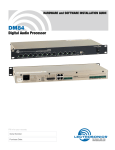
DM84 ...................................................................................................................................................................................................... 12
DM812 .................................................................................................................................................................................................... 12
DM1612 .................................................................................................................................................................................................. 12
DM1624 .................................................................................................................................................................................................. 12
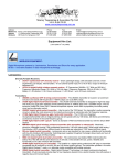
DMTH4 ................................................................................................................................................................................................... 13
PA8 ......................................................................................................................................................................................................... 13
DMPA12 ................................................................................................................................................................................................. 13
Venue Receiver ...................................................................................................................................................................................... 13
Wired Remote Controls .......................................................................................................................................................................... 14
RCW-DMTH4 ......................................................................................................................................................................................... 14
RCW-VLS ............................................................................................................................................................................................... 14
RCW-TEL ............................................................................................................................................................................................... 14
RCW-PB4 ............................................................................................................................................................................................... 14
Example Sound System Designs .......................................................................................................................................................... 15
Boardrooms, Traning
and Conference Centers ........................................................................................................................................................................ 15
Courtroom Sound Systems ................................................................................................................................................................... 15
DM1612 in Multi-Room Combining ....................................................................................................................................................... 15
Worship Center Automated Sound Systems ......................................................................................................................................... 15
City Council Chamber ............................................................................................................................................................................ 15
Collegiate Distance Learning/Multi-Purpose Hall ................................................................................................................................. 15
Boardrooms, Traning and Conference Centers ..................................................................................................................................... 16
Worship Center Automated Sound Systems ......................................................................................................................................... 17
Courtroom Sound Systems ................................................................................................................................................................... 18
City Council Chamber ............................................................................................................................................................................ 19
Multi-Room Combining .......................................................................................................................................................................... 20
Collegiate Distance Learning/Multi-Purpose Hall ................................................................................................................................. 21
Calculating PAG, NAG and POWER ....................................................................................................................................................... 22
The PAG-NAG Computer Program ......................................................................................................................................................... 22
What is NAG? ........................................................................................................................................................................................ 22
What is PAG? ......................................................................................................................................................................................... 22
What About Loudspeaker Power? ......................................................................................................................................................... 23
PAG-NAG Software GUI ........................................................................................................................................................................ 24
Introduction to Writing Macros for LecNet2 ......................................................................................................................................... 24
In General .............................................................................................................................................................................................. 24
Query ..................................................................................................................................................................................................... 24
Update .................................................................................................................................................................................................... 24
Command .............................................................................................................................................................................................. 24
LecNet Command Terminal ................................................................................................................................................................... 24
Creating Macros in LecNet2 .................................................................................................................................................................. 25
Assigning Macros to External Buttons .................................................................................................................................................. 25
Advanced Macros .................................................................................................................................................................................. 25
A Brief History of Product Development .............................................................................................................................................. 26
www.lectrosonics.com
3
LecNet2™
LecNet2 Overview
LecNet2 Remote Control
The LecNet2 product group introduces a powerful
series of audio components and unique solutions for
the design and installation of audio systems. This
Design Guide provides basic information on LecNet2
components, automatic mixing, the mix-minus approach
to loudspeaker zoning, and specific information on
audio teleconferencing. A variety of sound system block
diagrams are included as examples of different applications for LecNet2™ components.
There is much more to the story than the hardware.
From the start we wanted to outfit these new products
with a truly simple, robust and flexible remote control
capability. The goal was to make life easier for third
party control developers and let them focus on designing great control applications, rather than wrestling with
the underlying protocols. The result is the LecNet2
Control System consisting of a streamlined command
protocol that is human readable and transport neutral.
Applications for LecNet2 products include worship
centers, courtrooms, paging systems, training and
conference centers, council chambers and hotels. A
single LecNet2™ sound system can provide teleconferencing, sound reinforcement and multiple mixes for
recording all at the same time. LecNet2 components will
operate as stand-alone devices or as part of a larger
integrated system in order to provide a multitude of
functions in simple-to-use, cost-effective rack-mounted
assemblies.
•
Two high speed communication ports in every
Lecnet2 device, USB and RS-232
•
Visual command monitor built into many LecNet2
devices
•
PC hosted Command Terminal program for easy
testing and debugging
•
PC hosted Net Server program which allows control
of LecNet2 devices over a network connection
USB and RS-232 compatible interfaces allow connection with all LecNet2 components, providing the supplied control software to communicate with each
component. Individual function settings and signal
routing can be customized for a particular application
during setup, recalled from various screens during
operation, or recalled by other brands of remote control
systems. The LecNet2 serial port is completely compatible with control systems from AMX®, Crestron®, and
any other equipment with RS232 interface compatibility.
In addition, a DANI (Digital Audio Network Interface) is
provided so that the digital audio outputs of the master
and slave units can be connected in stacked
configuratons for larger applications.
The command protocol is designed to be compatible
with existing remote control platforms yet easy to
program for. LecNet2 includes helpful tools like the
command terminal program which allows a human to
communicate with a LecNet2 device interactively. It is
used to send commands and view the responses, much
like working at the command prompt of a computer.
Since the LecNet2 protocol has a clean, human readable syntax the commands and responses are easy to
understand and debug. Incoming commands can also
be viewed on the LCD screen of LecNet2 devices for
troubleshooting purposes. LecNet2 is a system with
high visibility into the command protocol.
The nature of the LecNet2 protocol makes it “transport
neutral”, allowing it to be carried over a USB connection, an RS-232 link, or a network connection using the
HyperText Transport Protocol (HTTP). This offers great
flexibility in designing remote control applications.
LecNet2 devices ship with both an RS-232 port and a
USB port, with the operation of the Lecnet2 command
protocol identical over each. Network connections to
LecNet2 devices are possible using the PC hosted
LecNet2 Net Server program. In either case complete
control is possible by sending commands using the
HTTP protocol, with even a humble web (HTML) page
capable of simple functionality. LecNet2 is an open
system for which controllers are easy to implement.
It is worth noting that the command terminal program is
capable of accessing LecNet2 devices using any of the
three connection types mentioned above, and may be
used as a remote control and configuration tool for all
LecNet2 devices. We think you will agree - LecNet2
offers unprecedented flexibility and convenience for
remote control developers and system designers.
4
LECTROSONICS, INC.
System Design Guide
Automatic Microphone Mixing Algorithm
Sound reinforcement systems with multiple microphones and a distributed loudspeaker system are the
rule in conference rooms, training rooms and boardrooms. In many cases the room has a low ceiling, which
increases the acoustic coupling between loudspeakers
and microphones, creating a significant challenge to
providing adequate gain for sound reinforcement
without acoustic feedback. In larger rooms with longer
reverberation times, reinforced sound is re-circulated
through multiple open microphones which can severely
reduce the intelligibility of the overall sound system.
Automatic microphone mixers are an effective tool to
minimize the effects of multiple microphones. All automatic mixers seek to open only those microphones which
are being spoken into at any given time. Keeping the
number of open microphones to a minimum reduces recirculated sound to improve intelligibility and eliminate
acoustic feedback.
Automatic microphone mixers attenuate unused microphones following the rule that the gain applied to all
open microphones is distributed among them so that it
is always equal to a single open microphone. This
process is commonly referrred to as NOM = 1, or the
Number of Open Microphones = 1. Following this rule,
a sound system will perform the same with multiple
microphones as it does with a single microphone with
respect to feedback stability and intelligibility.
While all automatic mixers turn microphones on and off
and implement some form of NOM attenuation, they are
not all equally effective. The Lectrosonics automatic
mixers employ a patented proportional gain algorithm*
to distribute gain across all channels in a seamless
manner. An overall reference level is created by summing all channels. Then, each individual channel is
compared with the overall reference level, and attenuated by the difference between its level and the reference level. The channels with the highest microphone
signal levels thus receive proportionally higher gain
than inactive or less active microphones.
NOM = 1 attenuation along with an adaptive threshold
is inherent in this algorithm. As a result, accurate setup
is as easy as using a standard mixer. And by using this
continuous gain modulation technique, abrupt level
changes and other anomalies normally generated by a
switching or gating method are eliminated.
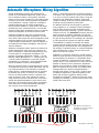
An additional feature of the Lectrosonics automatic
mixing algorithm is an “intelligent” method of keeping
track of which channel has been the loudest for the
longest time period and skewing a “priority” toward that
channel in the mix. This AutoSkew™ process gives the
priority channel up to 6dB of additional gain over the
other channels making it appear to be more dominant in
the gain-sharing allocation. The skewing rate is damped
to avoid abrupt level changes that might be audible.
The AutoSkew™ algorithm also keeps non-speech
transient sounds (coughs, bumps, clicks and pops) from
affecting the gain allocated by the auto mixing process.
For example, if someone bumps an unused microphone
while someone else is talking, the gain of the microphone in use will not change.
AutoSkew™ is especially important in sound systems
where the talker may be in close proximity to more than
one microphone. For example, in a boardroom where
multiple microphones are placed next to one another
along a table, it is very common that a talker leans one
direction or the other and is momentarily equidistant
between two microphones. If both microphones were
open and mixed at the same level, very audible comb
filtering would occur. Another example would be a
worship center where a person using a wireless lapel
microphone approaches a gooseneck podium microphone and the voice is picked up equally in both
microphones. AutoSkewTM reduces or eliminates comb
filtering by not allowing any two or more channels to be
mixed at the same level.
AutoSkewTM increases the
dominance of the most active
microphone channel.
*US Patent 5,414,776
www.lectrosonics.com
5
LecNet2™
Mix-Minus Loudspeaker Zoning
Sound reinforcement systems installed in rooms with
low ceilings often use multiple ceiling-mounted speakers distributed throughout the room in order to provide
even coverage. When multiple microphones are used,
as in a conference room, achieving any significant
sound system gain before feedback can be difficult.
Since system microphones will almost always be in the
direct sound field of one or more of the distributed
loudspeakers, feedback is virtually assured. Automatic
mixers help the situation by minimizing the number of
open microphones. Even with an automatic mixer,
however, there may still be a need for some form of
loudspeaker control in order to get acceptable GBF.
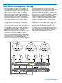
The Mix-Minus approach to loudspeaker zoning eliminates both of the problems mentioned above. Individual
outputs from each microphone channel are delivered
only to loudspeakers located far enough away from the
microphone to eliminate feedback. In essence, the
microphones and loudspeakers are physically
decoupled. Mix-Minus systems using automatic mixers
are even more stable against feedback, since the
automatic NOM attenuation in the mixer reduces the
gain on unused microphones. Mix-Minus routing does
not change the way an automatic mixer operates, and
in combined units such as the DM Series matrix
mixers, all of these functions are seamlessly integrated.
6
As an example, consider a conference room with
multiple microphones and ceiling speakers. Assume the
average distance from a microphone to its closest
loudspeaker is 6 feet. Using a DM matrix mixer, a MixMinus feed can be generated for each loudspeaker that
does not include the microphones close to each specific
loudspeaker. If, for example, the next closest microphone to a loudspeaker is on the order of 12 feet away,
the sound system will have picked up 6dB more gain
before feedback. In difficult acoustic circumstances, 6dB
may be the difference between a functioning sound
reinforcement system and an expensive problem.
DM Series matrix mixers combine the elegance of the
LecNet2 automatic mixing algorithm combined with the
feedback reduction and stability of Mix-Minus. This
design architecture provides an outstanding foundation
for sound systems to simultaneously provide reinforcement, teleconferencing and recording. Mix-Minus also
reduces echoes heard at the far end of a teleconference, while full duplex operation is preserved
LECTROSONICS, INC.
System Design Guide
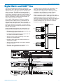
Digital Matrix and DANITM Bus
The core of the DM Series processors consists of a
digital matrix and a digital bus called DANI (digital audio
network interface). The digital matrix is common to all
units in a system. The DANI bus interconnects the
hardware to allow access to the matrix signal flow and
transfer data required for automatic mixing functions. In
order to understand the power and functions available
with this architecture it is helpful to think of them as
entities separate from the hardware.
In this sense a DM processor is simply a hardwarebased tap into the digital matrix via the DANI bus to
interface various types of microphones and audio
equipment with the digital matrix. Thus connected, the
processors distribute audio signals and share information about each input and output to provide a myriad of
features and functions.
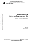
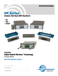
When multiple DM processors are stacked, each unit
participates with the digital structure in several ways:
The digital matrix is common to all processors in the
stack, with automatic mixing taking place at the
crosspoints in the digital matrix. The output of each
crosspoint is then available at a variety of output
terminals on various processors in the stack.
Different processor models interface with the digital
matrix in different manners. Audio signals and data are
propagated from the Slaves to the Master unit in a
stack, then the data and some of the final mix signals in
the Master are back propagated to the Slaves. This
provides additional final mix outputs at the output
terminals on the Slave units.
Master
DM Series
Processor
Slave
DM Series
Processor
Slave
DM Series
Processor
• Passing back-propagated final mix signals from the
unit above it to the next unit below it
• Applying gain and signal processing to the audio
signals at its input terminals
• Delivering audio signals to its output terminals as
selected by the setup
• Applying signal processing to the signals routed to
its output terminals
Automatic Mixing Matrix
• Delivering audio signals from its input terminals into
the forward-propagated submix bus
• Receiving and transmitting data required for the
automatic mixing process in the matrix
Audio Submix
and Data
Forward Propagation
Audio Final Mix
and Data
Back Propagation
Audio Submix
and Data
Forward Propagation
Audio Final Mix
and Data
Back Propagation
MASTER
SLAVE
SLAVE
www.lectrosonics.com
7
LecNet2™
Teleconferencing with DM Series Processors
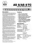
The fundamental problem in teleconferencing with a
sound system is microphone/speaker acoustical
coupling as is illustrated below. Far end audio is
delivered by the loudspeakers in the room and the
microphones pick it up and return it to the far end. The
delay through this process creates an echo heard on
the far end.
Local
sound system
Telephone
Interface
Far-end
Local
loudspeaker
Local
microphone
There are several methods used to reduce or eliminate
the echo heard on the far end of the conversation:
• Optimal design in the sound system to minimize the
coupling between loudspeakers and microphones.
• Mix-minus matrix routing.
• Automatic microphone mixing.
• Digital acoustic echo cancelling.
Matters become more complex when the sound system
is required to provide both teleconferencing and sound
reinforcement. A gain proportional automatic mixing
process is widely recognized as the optimum solution
for sound reinforcement, but it places significant demands on an acoustic echo canceller used for teleconferencing.
ERL
ERL (echo return loss) refers to the natural attenuation
of the far-end audio signal as it circulates from the farend through loudspeakers and microphones in the local
sound system and back to the far-end. Good design in
the local sound system will reduce the acoustic coupling between loudspeakers and microphones using
physical placement and mix-minus matrix routing.
Depending upon room size and acoustics, it is often
impossible to achieve adequate decoupling to avoid an
echo heard by the far-end during a teleconference.
Thus, other types of processing are needed to further
reduce the return echo.
ERLE
ERLE (echo return loss enhancement) refers to additional circuits and processes used to further increase
ERL. Common methods are to use automatic mixing
and digital echo cancellation.
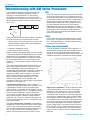
Return Loss Enhancement
The gain proportional automatic mixing algorithm* in
the DM Series processors not only provides seamless
mixing for local sound reinforcement without abrupt
gating, but it also contributes significantly to ERLE. The
additional contribution is plotted in the following graph.
The matrix mixer enables complex signal routing and
level controls without limitations. The matrix mixing
allows "mix-minus" zoning of microphones and
loudspeakers to decouple them and reduce or eliminate
acoustic feedback and echoes. NOM attenuation is
applied by the DSP at the crosspoints in the matrix,
which essentially provides 24 separate automatic
mixers, each with its own NOM mixing bus. Four
different mixing modes can be selected at the
crosspoint for each input, so each input can participate
differently in each output mix.
The automatic mixing process uses a seamless
algorithm that eliminates gating and its ill-effects. Gain
is proportioned among all inputs assigned to each
output channel in a seamless and continuous manner
based upon microphone activity. The algorithm incorporates an adaptive AutoSkew™ process to eliminate
artifacts such as comb filtering and abrupt gating that
occur with conventional automatic mixing schemes.
Audio from the far-end of a conference participates in
the local mixing algorithm just like a microphone in the
local sound system.
Two digital acoustic echo cancellers are provided in
the DMTH4 to further reduce the return of local signals
to the far-end. One operates on the telco connection
and the other is dedicated to the video codec connection. In conjunction with the automixing process,
echoes are minimized and not heard at the far end.
8
Digital echo cancellation is another method of reducing the echo delivered to the far-end. The concept,
described in very simple terms, is to have the DSP
recognize the far-end audio and subtract it from the
transmitted audio to remove any echo they might hear
at the far-end. Sounds simple, but in a sound system
with multiple microphones and loudspeakers, it is not
easy to identify the far-end audio in the complex mix of
local sound, local noise and the effects of the room on
the far-end audio delivered by the local loudspeaker
system. When there is no sound or noise in the local
room, the DSP can do a decent job of identifying the
far-end audio and subtracting it from the transmitted
signal, but this is rarely the case in full duplex teleconferencing.
LECTROSONICS, INC.
System Design Guide
In a simple sound system arrangement, the local
microphone can be muted when nobody is talking in the
local room. A simple gated mixer can provide this
function. With no open microphones locally, there is
obviously no return echo signal. This requires that a
threshold level be set high enough to keep the microphone from being opened by background noise, but low
enough to allow it to open when someone speaks.
When the local microphone is open, a return echo path
is created, which is when a DSP echo canceller is
needed. Given the wide variety of human voices and
the dynamics of noise in a meeting room, a gated mixer
is often not the best choice.
Using a dedicated DSP echo canceller on each input of
the local mixer (referred to as “distributed echo cancellation”) is an expensive but effective approach to
reducing the return echo. The process requires the
algorithm to “converge,” which is to identify the far-end
audio and subtract it from the signal sent to the far-end.
This requires at least a brief moment when there is very
little local sound or noise, with significant far-end audio
present in the room. If nobody moves and there are no
gain changes made to local microphones and loudspeakers, it is possible (in theory) to effectively remove
return echo, but this is not a very realistic situation.
The theory behind distributed echo cancelling is that
once the DSP has converged, it can continue to subtract far-end audio even when the local microphone is
open and far-end audio is present at the same time. If
there are any changes in gain, noise or acoustics in the
local space and equipment, the DSP must re-converge,
which requires another brief moment with little or no
local noise or sound, and significant far-end audio
present.
A gated automatic mixer does not change the gain
when the microphone is open, it just turns the channel
off and on abruptly. This helps with distributed echo
cancelling since the microphone is completely muted
when not in use, but it is very “choppy” sounding in the
local sound reinforcement system.
A gain proportional automatic mixer applies the most
gain to the most active microphone with smooth,
continuous changes. This makes it extremely effective
for local sound reinforcement, but the continuous gain
changes make it difficult for the echo canceller to
remain converged and effectively reduce the echoes at
the far end.
The DMTH4 in conjuction with a DM Series processor
offers a unique approach to the problems with simultaneous teleconferencing and sound reinforcement. The
patented adaptive gain proportional mixing algorithm
works in conjunction with a centralized echo canceller
to address a variety of issues. The automatic mixer
provides seamless allocation of gain to local microphones through a mix-minus matrix to reduce background noise and decouple loudspeaker and microphones, while a very fast converging DSP echo cancel-
www.lectrosonics.com
ler operates on the composite transmitted signal being
sent to the far end. This combination of processes is
possible only with the latest DSP technology.
The auto mixing algorithm adapts to changes in background noise continuously, and unlike a gated mixer
there are no threshold levels to adjust. A sum of all
channels is the reference signal, each channel level is
compared to this reference and the individual channel
gain is adjusted to apply NOM attenuation. Gain is
adjusted continuously to eliminate audible artifacts that
gating and abrupt level changes can cause. As the
common mode noise in the room changes, all channels
are affected equally. The end result is seamless,
adaptive auto mixing that requires no calibration or
threshold adjustments.
Each individual output of the matrix operates as a
separate NOM bus, so a particular input can be assigned to multiple outputs with mix parameters adjusted
differently for each output. In other words, gain and mix
mode are configured independently for each matrix
crosspoint, resulting in great flexibility. Four mix modes
are supported: Auto, Direct, Override and Background.
The echo canceller converges continuously when the
level of the far side signal exceeds a minimum level,
and the ratio of the far side signal to local room sound
exceeds a minimum ratio. This dynamic control prevents
divergence during periods of silence from the far side
room or in “doubletalk” situations. The convergence
takes place very quickly to keep up with the changes
made by the automatic mixing algorithm and other
changes that occur in the room. Setup is greatly
simplified and any adjustments, such as level changes
made with a remote control system, are accommodated
automatically.
The convergence speed is adjustable in the control
panel GUI to fine tune it to a particular situation. Faster
convergence times can track changes in the room
almost instantaneously, but the depth of echo cancellation will be reduced. Slower convergence times take a
bit longer to fully converge, but produce greater echo
cancellation. The ERLE value achieved by the echo
canceller is displayed on the GUI and the effects of
altering the convergence rate will be immediately visible
and audible.
An important final note on the DMTH4 is the fact that
the echo canceller will never “diverge” (lose convergence). This unique algorithm will also converge on a
continuous sine wave, which is especially important
when DTMF tones are present in the room. Since the
echo canceller will never diverge, there is no need for a
“panic button” (as is used in other designs) to generate
a noise burst to help the echo canceller re-converge.
9
LecNet2™
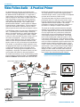
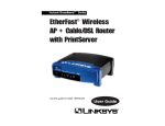
Video Follow Audio - A Practical Primer
As teleconferencing advances and becomes more
common, new design requirements have risen that can
be addressed with the DM Series. In a large room, a
single camera can only deliver an image of the entire
table, leaving the far-side viewers to guess which of the
little talking heads in the picture is actually speaking.
Video follow audio methods allow the video signal to
track the audio conversation. This is done via two
possible control methods - pan/tilt cameras or multiple
cameras through a video switcher. To do so requires a
signal from the automatic mixer that lets the camera
control system know to which zone to bring the camera.
The DM Series mixers have two ways of providing this
data. If controlling the system through a third party
device, the control system can acquire the information
via the serial port. The programmer codes a looped
inquiry that constantly polls the mixer for the status on
the various microphones. When the microphone
comes to within 6dB of full gain, the control system is
notified via the serial port and either switches to the
correct camera or calls up the new pan/tilt coordinates.
The second, and sometimes simpler, method is to set
the programmable outputs of the DM Series to emulate
a contact closure upon activity at any given set of
microphones. Entire groups of microphones can be
assigned to a single pin. The contact closure can then
activate either the switcher or the pan/tilt platform.
To smooth the switching activity, the DM mixers provide
programmable parameters for both input qualification
time and hold time. Qualification time is the time that
the DM will withhold the notification of channel activity.
This helps prevent a switcher from triggering when
someone coughs, moves a paper, bumps a microphone
or some other momentary sound occurs.
The Hold time keeps the contact closed if the microphone goes quiet, to avoid losing the camera simply
because someone pauses briefly. Both parameters are
adjustable from 0 to 25.5 seconds in 0.1 second
increments to prevent false triggering or jumpiness in
the video as it attempts to follow a conversation.
This leads to the other question before the designer:
whether to use multiple cameras or pan/tilt platforms.
That often depends on the nature of the conferences.
For very large and/or very active rooms, where the
conversation may be unstructured and free flowing,
using multiple cameras will work better. Pan/tilt platforms, while reducing the number of cameras, fail to
travel quickly enough during a lively discussion to offer
easy tracking of the video to the audio. Given the lower
costs of cameras compared to pan/tilt mechanisms, the
multiple camera design makes better sense in many
cases. If used in a smaller room or where the order of
conversation is more structured (for example, Roberts
Rules of Order in a council chamber), then a pan-tilt
design can offer smooth transitions from one microphone location to the next, emulating the movement of
one’s head if they were observing the dialogue.
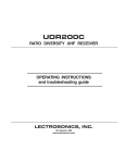
Please Note: Automated switching works best with
systems of 5 or more microphones.
1. Active Talker triggers camera switch
via DM1624
3. Camera
Picks up
Active Talker
Single Camera View
DM1624
4. Video as
seen by Far
end
DMTH4
Video Conferencing Codec
Video Switcher
10
2. Direct Control by
DM1624
OR
Optional
Control System
for switching
Video Follow Audio
LECTROSONICS, INC.
System Design Guide
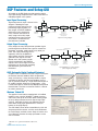
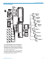
DSP Features and Setup GUI
All models in the DM Series provide extensive digital
signal processing to optimize each audio channel for its
intended purpose in the system.
Indicator
Indicator
Activity Indicator
Input Signal Processing
Clipping
Signal flow for each input is shown in this
Detector
diagram. Following the input
preamp and level control are the
A/D
processing stages for delay, six
filter stages, six ADFE feedback
eliminators and a compressor.
Coarse Gain
Fine Gain & Polarity
0 to 50 dB,
-10 to 10 dB,
Every function and feature on
10 dB steps
1 dB steps
every stage can be fully impleInput Gain & Polarity
-10 to +60 dB
mented on every input channel
1 dB steps
since there is no limitation on
the resources available.
Gain Reduction Indicator
Level Meter
Delay
0 - 1s
0.5 ms steps
Six Filter
Stages
Six ADFE
Filters
Off, LP, HP, BP,
PEQ, LS, HS
6 or 12 dB/oct.
Butterworth or Bessel
when applicable
Enable/Disable
Compressor
Threshold
Comp. Ratio
Attack TC
Release TC
Input Processing Stages
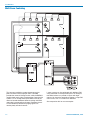
Output Signal Processing
Every output on every DM processor provides signal
processing block to idealize the signal for sound reinforcement, recording, media feeds or any other purpose. The signal processing chain is
especially useful in the DMPA12
Delay
digital power amplifier. Back propagated final mix signals from the
Master unit in the system are indi0 - 5s
vidually processed at the DMPA12
0.5 ms steps
outputs, so the same signal mix from
the Master can be used for recording,
teleconferencing and sound reinforcement.
Indicator
Activity Indicator
Gain Reduction Indicator
Activity Indicator
Level Meter
Filter Stages
Compressor
Limiter
Off, LP, HP, BP,
PEQ, LS, HS
6 or 12 dB/oct.
Butterworth or Bessel
when applicable
Threshold
Comp. Ratio
Attack TC
Release TC
Threshold
Comp. Ratio
Attack TC
Release TC
Output Gain
-70 - +20 dB
1 dB steps
Typical Output Processing Stages
(varies slightly by model)
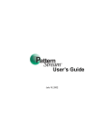
ADFE (Automatic Digital Feedback Eliminator)
A special filter is included in the DSP stage at the inputs
to eliminate acoustic feedback. With the processor
setup and running, a setup wizard provides a simple
procedure to identify and eliminate feedback. As the
gain is gradually turned up, a slight oscillation begins to
be audible (ringing). When the ringing begins, a very
narrow notch filter is automatically deployed to eliminate
the oscillation. The filter can then be stored in a Preset
to make it permanent.
The ADFE setup wizard
Windows Tabbed GUI
The graphical user inteface supplied with all LecNet2
products uses a familiar Windows® tabbed structure.*
Tabs across the top of the screen open working pages
to set up the parameters for each type of signal processing. Individual channels are selected and and
other detail setup pages opened with a variety of
buttons in the page display.
The GUI allows values to be entered directly, click and
drag setup with the mouse, and click and hold buttons
to scroll through available values. Setup is intuitive and
visual displays illustrate the setup parameters as the
data is entered.
* Windows® is a registered trademark of Microsoft,
Corp.
www.lectrosonics.com
11
LecNet2™
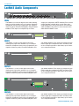
LecNet2 Audio Components
DM84
The DM84 is an 8-in/4-out digital matrix mixer allowing
every input to be routed to any or all outputs. Automatic
microphone mixing using a proportional gain algorithm
allows for greatly increased intelligibility and gain before
feedback. Each input can incorporate up to 6 filter
stages plus compressor, ADFE and delay. Each of the 4
outputs provides a digital delay, up to 9 filters and a
compressor/limiter. Front panel controls and indicators
allow the DM84 to be used in a similar manner to the
older AM8 and AM8/TC units.
DM812
The DM812 is an 8-in/12-out digital matrix mixer
allowing every input to be routed to any or all outputs.
Automatic microphone mixing using a proportional gain
algorithm allows for greatly increased intelligibility and
gain before feedback. Each input can incorporate up to
6 filter stages plus compressor, ADFE and delay. Each
of the 12 outputs provides a digital delay, up to 9 filters
and a compressor/limiter.
DM1612
The DM1612 is a 16-in/12-out digital matrix mixer
allowing every input to be routed to any or all outputs.
Automatic microphone mixing using a proportional gain
algorithm allows for greatly increased intelligibility and
gain before feedback. Each input can incorporate up to
6 filter stages plus compressor, ADFE and delay. Each
of the 12 outputs provides a digital delay, up to 9 filters
and a compressor/limiter.
DM1624
The DM1624 is a 16-in/24-out digital matrix mixer
allowing every input to be routed to any or all outputs.
Automatic microphone mixing using a proportional gain
algorithm allows for greatly increased intelligibility and
12
gain before feedback. Each input can incorporate up to
6 filter stages plus compressor, ADFE and delay. Each
of the 24 outputs provides a digital delay, up to 9 filters
and a compressor/limiter.
LECTROSONICS, INC.
System Design Guide
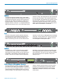
DMTH4
The DMTH4 integrates telephone lines, video codecs
and external audio sources into the digital bus structure
of DM Series processors so these sources operate as
though they are another microphone or audio input in
the sound system. The unit is much more than just a
telephone interface. Instead, it is a complete DM Series
digital matrix processor, with a 3-in/24-out digital matrix,
automatic mixing and comprehensive signal processing
on every input and output. Two acoustic echo cancellers are provided, one dedicated to the CODEC and the
other to the TEL connection. An extremely fast echo
cancellation algorithm converges so fast it tracks and
adapts to the level changes in the auto mixing process,
which allows centralized echo cancellation.
PA8
The PA8 analog power amplifier provides 8 discrete
channels for use in multi-speaker sound systems. It is
fully protected from open and shorted outputs and
thermal overheating. Features include individual level
controls on each channel, depluggable input and output
connectors, passive cooling and a single rack space for
installation in standard 19" racks. Adjacent channels
can be bridged for added power output.
DMPA12
The DMPA12 is a digital 12-channel power amplifier
and DSP processor in a single, 19" rack enclosure.
Audio inputs are taken from the final mix signals back
propagated via the DANI bus from the Master in the
system. These final mix signals are then processed
individually at each output channel in the power amplifier to apply digital delay, equalization filters, compression and limiting. The unit runs very cool with 10 Watts
per channel using Class D amplifiers and passive
cooling (no fan).
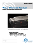
Venue Wireless Microphone Receiver
The Venue Receiver system is a modular UHF design
that operates with Digital Hybrid Wireless™ transmitters, and a variety of analog transmitters. It consists of a
Venue Receiver Master (VRM) and one to six plug-in
receiver modules. The VRM includes an antenna multi-
www.lectrosonics.com
coupler, computer communications interface and the
mechanical rack mounting for the receiver modules.
Supplied software allows the Venue receiver to be
addressed via RS232 or USB as part of a LecNet2
audio system.
13
LecNet2™
Wired Remote Controls
RCW-DMTH4
RCW-TEL
• Connects directly to the
Remote Control Port (DB9) on the DMTH4
•
Remote Control for
DMTH4 Digital Telephone
Hybrid
• Brings the hybrid front
panel controls to a table
top surface
•
LEDs for Connect and
Privacy status
•
• LED indicators display
status and volume
adjustment activity
Push-button switches for
remote volume control
•
Fits single-gang conduit
box
• Soft-touch switches
•
• Durable laser-engraved
nomenclature
Connects to a DB-9
connector on the DMTH4
•
7-conductor wiring with
screw terminals
• Machined aluminum housing
The RCW-DMTH4 provides the main operating controls
for the DMTH4 hybrid in a remote location. The circuit
board is mounted in an attractive, powder-coat finished
box. Soft touch switches and highly visible LEDs
provide simple, intuitive operation and instant recognition of the status of the DMTH4. Two RCW units would
be used if the DMTH4 is connected to both an analog
line and a codec. This allows independent control of
both sources during a bridges three-way (room/video/
audio) conference.
RCW-VLS
Remote Level Control for
Lectrosonics auto mixers,
models: AM8, AM8TC,
AM8/4, AM16/12, DM84,
DM812, DM1612 and
DM1624.
The RCW-TEL provides the
main operating controls for the DMTH4 hybrid in a
remote location. The circuit board is mounted to a
single-gang wall plate. Soft-touch switches and highly
visible LEDs provide simple, intuitive operation and
instant recognition of the status of the DMTH4. Two
RCW-TELs would be used if the DMTH4 is connected
to both an analog line and a codec. This allows independent control of both sources during a bridged threeway (room/video/audio) conference.
RCW-PB4
•
Remote control for DM
Series products
•
4 Momentary contacts
•
4 Indicator LEDs
•
• LED indicates active
status
8-Conductor wiring with
screw terminals
•
• Screw terminal connections for reliability
Fits single-gang conduit
box
•
Four customizable
function labels
• Fits single-gang conduit
box
• Detented rotary action
• Selectable (by jumper)
FULL or -15dB attenuation
• 3-conductor wiring
The RCW-VLS is a rotary volume control mounted on a
circuit board and a single-gang wall plate for use with
Lectrosonics automatic mixers and matrix units. The
rotary action is detented for a smooth, accurate feel and
repeatable selection. The unit can be connected to
control individual channels in any combination or to the
main output control point on units with VCA taps. It is
also used as an analog control on units with Programmable Input connections. Fully clockwise, no attenuation is applied. Full counter clockwise, the level is either
fully attenuated or is reduced to -15dB, as determined
by an internal jumper on the circuit board.
14
The RCW-PB4 is designed
to provide remote control
capability with any DM Series product by actuating
macros, presets, or level controls. The RCW-PB4
connects via any small gauge multiconductor wiring to
the DB25 connector on the DM series units. This control
can be configured in the DM software to actuate
virtually any function including (but not limited to)
complete signal routing changes, group or individual
level controls on inputs or outputs, or even change the
nature of the automix functions. LED’s can be programmed independently from the buttons for status
indicators or user feedback.
LECTROSONICS, INC.
System Design Guide
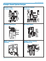
Example Sound System Designs
Boardrooms, Training
and Conference Centers
Worship Center Automated
Sound Systems
Courtroom Sound Systems
City Council Chamber
CD Player
DM1612 in Multi-Room
Combining
www.lectrosonics.com
Collegiate Distance Learning/
Multi-Purpose Hall
15
LecNet2™
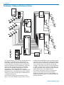
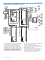
Boardrooms, Training and Conference Centers
This diagram details a sound system appropriate for the
boardroom or conference room. The installation includes both audio and video teleconferencing (which
can be bridged for simultaneous 3-site conversations),
automatic recordings of these conferences, tape input,
control systems and speaker zoning. The DM1624
takes input and provides automixing from 12 wired
microphones, three wireless bodypack systems,
telephone lines, via the DMTH4, and a hard-disk media
recording system. In teleconferencing modes, whether
audio only or video, the audio from the teleconference
is recorded automatically.
Due to the low ceilings typically founding in boardrooms, a mix-minus speaker routing system is recom-
16
mended. Using the DM1624 matrix, 16 speaker zones
have been set up. The DSP control within the DM1624
allows zone-specific equalization and feedback control.
The 16 speaker zones are amplified with two PA8
amplifiers. Control of the system can be achieved with
an AMX or Crestron control system. Programming can
be easily altered on site by updating macros using the
USB or RS232 ports and LecNet2 software.
The wireless microphone system is a Lectrosonics
Venue receiver loaded with three VRS modules.
Bodypack transmitters can be LM, SM, UM400 or, by
setting compatibility modes, any transmitters from the
previous 200 series.
LECTROSONICS, INC.
System Design Guide
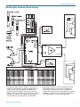
Worship Center Automated Sound Systems
This diagram shows how the DM84 can be used as an
automatic “front end” for the speech microphones in a
church system. All of the speech microphones are
passed through the DM84. The direct outs from the
DM84 are then input to separate channels of the mixing
console. Full control over the speech microphones is
maintained by the console operator, but the DM84
www.lectrosonics.com
eliminates the need for routine “microphone chasing.”
The console operator is thus free to concentrate on
other mixing and adjustment tasks. In addition, for
worship services where no console operator is present
(weddings, funerals, etc.), the addition of the DM84 to
the console provides fully automatic operation.
17
LecNet2™
Courtroom Sound Systems
This diagram shows a typical courtroom sound system,
including microphones for each of the key people, an
automatic mixing function, and a recording system. A
70 volt distributed speaker system is fed from a main
output on the DM1612. A multi-media rack provides
input signals from audio and video recordings.
18
LECTROSONICS, INC.
System Design Guide
City Council Chamber
CD Player
This is a representation of a typical City Council Chamber, including microphones for 16 council members,
podium, tables and wireless systems. Ample inputs are
provided for various audio-visual sources. Multiple PA
zones feed the main chambers along with the audience
seating areas. Press feeds are provided as is an output
for an assistive listening system.
Any number of additional inputs can easily be added by
expanding the system with one or more DM matrix
mixers. Up to 24 presets and 128 macros can be used
for multiple setups and user scenarios.
www.lectrosonics.com
19
LecNet2™
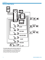
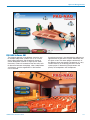
Multi-Room Combining
This four-room combining system features one microphone and one auxiliary input per room. The DM84
provides the automatic mixing function, while the DMPA12
amplifier feeds each of the 12 loudspeakers. Control of the
system is via an analog control panel either in one of the
rooms or located elsewhere. Automatic mixing and NOM
attenuation is preserved in each room. Background music
can be individually selected and paging signals can
receive priority over local sources.
20
Larger systems can be configured with additional DM
units connected via the expansion ports. For example,
two DM84 mixers can provide 16 inputs with eight
outputs. An alternative would be to choose a larger DM
matrix mixer, such as a DM1612 or DM1624.
See companion disk for macro examples.
LECTROSONICS, INC.
System Design Guide
Collegiate Distance Learning/Multi-Purpose Hall
This example illustrates a large distance learning room
with forty microphones, three-site conferencing (local,
Video, and Telco), and several multi-media inputs.
The design provides extensive signal processing,
including EQ, compression, delay, automatic feedback
suppression, automatic microphone mixing, mix-minus
speaker zoning and stereo playback over the main
Program speakers. A large gallery audio feed with time
delay compensates for the difference in distance from
www.lectrosonics.com
the speakers near the freshmen seats in the back of the
room to the front program speakers.
All of this is possible with just three DM1624 mixers,
power amplifiers, and speakers. No additional signal
processing devices are required.
The touch screen control system can be easily programmed using simplified serial command strings and
up to 128 resident macros. Up to 24 presets allow
global recall of settings for alternate setups.
21
LecNet2™
Calculating PAG, NAG and POWER
The PAG-NAG Computer Program
The GAINCALC software is a proprietary program
offered by Lectrosonics on our CD ROM and by download from the web site as a part of the LecNet2™
sound system Designer’s Kit. The supplied software
includes EPS graphic files of LecNet2™ component
control panels, block diagrams in DXF format of the
sound system examples illustrated in this guide, and
engineer’s and architect’s specifications in TXT format
for all LecNet2™ components. The GAINCALC program
(which runs under Windows® 98/NT/XP*) is designed
to automate calculations of PAG, NAG and loudspeaker
electrical power requirements for any type of indoor
sound system.
The following are descriptions of each of the three
parameters calculated by the program, and some
information about how those calculations are made.
What is NAG?
Needed Acoustic Gain (NAG) is a measure of how
much reinforcement a sound system must provide so
that distant listener can hear a talker at a sound level
comparable to when the listener is near the talker. As
an illustration, assume that a listener near the talker
experiences an average sound pressure level (SPL) of
75dB in normal conversation without sound reinforcement.
Next, assume that a more distant listener hears the
same conversation at an average level of 62dB. This
level would be low enough that intelligibility could be a
problem, particularly in the presence of sound background noise. For the distant listener to hear normal
conversation at the same average level as the nearby
listener (i.e. 75dB SPL), an extra 13dB is needed at the
distant listener’s position. This is the Needed Acoustic
Gain (NAG) for this example.
In order to make a NAG calculation using GAINCALC,
the boxes labeled Dm, D0, Ld, and Lr must be filled in.
The formula for calculating NAG is:
NAG = Lr-Ld-20Log10(Dm/D0)
As should be clear, NAG is a function of the physical
distances between talkers and listeners. As yet, nothing
has been said about a sound system. If the NAG value
is positive, which it generally is, a sound system will be
needed to provide acoustic gain at least equal to the
NAG for the distant listener in order that they hear the
same SPL as the nearby listener. This leads to the PAG
calculation.
Download the program FREE from the web:
www.lectrosonics.com
What is PAG?
Potential Acoustic Gain (PAG) is a measure of how
much extra reinforcement (acoustic gain) the sound
system can be expected to provide for a distant listener
above the level at which that listener would hear the
talker without any sound reinforcement. Following
through from the NAG calculation above, the PAG of a
system should be at least equal to the NAG in order to
provide sufficient SPL to the distant listener.
The PAG calculation is based on the assertion that the
SPL generated by the sound system at the talker’s
microphone can cannot exceed the SPL that the talker
produces acoustically at the same microphone. If the
reinforced SPL exceeds the original SPL from the
talker, the system regenerates, producing what is
commonly known as FEEDBACK. The closer the
loudspeaker is to the microphone, or the farther away
the talker is from the microphone, the lower the PAG of
the system will be. The other factor in the PAG calculation is the distance of the distant listener from the
nearest loudspeaker. The further the listener is from the
speaker, the lower the system PAG.
In order to make a PAG calculation using GAINCALC,
the boxed labeled D0, D1, D2 and Ds must be filled in.
The formula for calculating PAG is:
PAG=20Log10((D1D0)/(D2Ds))
Note that the PAG calculated from this formula implies a
sound system which is right on the verge of feedback.
In the Options menu of GAINCLAC, you can check
FSM (Feedback Stability Margin) compensation. FSM
compensation will subtract 6dB from the calculated PAG
value to give a more realistic indication of PAG. More
explanation of what can be done to maximize PAG can
be found in the GAINCALC Help file.
What About Loudspeaker Power?
After the NAG and PAG calculations have been made,
it’s helpful to known how much amplifier power will be
needed to produce the desired sound system SPL.
GAINCALC uses the sensitivity data of the system
loudspeaker(s), the distance between the distant
listener and the closest loudspeaker, and the desired
SPL at the distant listener’s position to calculate the
needed amplifier power. Note that GAINCALC adds
20dB to the desired SPL factor Lr in order to account for
peak speech levels without clipping. One result of this is
that if you require high SPL at the distant listener’s
position, you’ll find yourself needing enormous amounts
of amplifier power.
In order to make a power calculation, you should fill in
the boxes labeled Spr Sens (db), @ Power (W), @
Distance, # of Speakers, Lr, and D2. The formula for the
power calculation is:
Power = # of speakers x10a
Where a= (Lr+20 SpkrSens 20xLog(SpkrDist/D2))/10
22
LECTROSONICS, INC.
System Design Guide
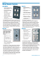
PAG-NAG Software GUI
The program operates in two different scenarios, one
for multiple loudspeaker systems such as in a boardroom (upper illustration) and the other for cluster or
central loudspeaker systems in larger spaces (lower
illustration). Values are entered into the data entry cells
for distances between microphone, talker, loudspeakers
and listeners, and the targeted SPL at the listener’s
ears is selected.
www.lectrosonics.com
A performance meter is also provided that indicates an
approximation of how well the system would work with
the given values. The meter updates continuously as
the different values are entered. The program is a very
valuable aid early in the design phase of a sound
system project in determining the placement and
quantity of loudspeakers and microphones.
23
LecNet2™
Introduction to Writing Macros for LecNet2
One of the most powerful features of the new DM Series
matrix mixers is the macro scripting language. The DM
Series products contain 128 global macros; furthermore,
each macro can hold up to 64 serial commands. If
needed, macros can be chained if a long sequence of
commands is required.
There are three types of instructions that can be contained
in a macro: Query, Update or Command. A Query will
always have a question mark (?) and an Update will
always have an equal sign (=). The Command will have
neither a question mark nor an equal sign.
In General
The syntax used for LecNet2 instructions closely follows
natural English in order to make it easy to use. For
instance, to set the input gain for channel 5 on a DM
unit to 0dB, we might say “Input gain of channel 5
equals 0dB”. This is a simple, understandable expression of the desired update. However, typing the above
expression might become cumbersome if a large
number of instructions were required in a LecNet2
application. Thus, the macro language is simplified to
be quick to type and yet still easy to understand.
To create the actual instruction line, first we abbreviate
“input gain” to “ingn” and shorten “channel 5” to simply
“(5)”. Thus we now have ingn(5). By adding the new
gain value to the input channel, the complete Update
instruction is now:
ingn(5)=0
Each instruction must then be followed with a carriage
return, notated as <CR>.
Query
In order to get specific information from a DM mixer, the
Query instruction is used to request the specific value
needed. For instance, to determine the output gain
value of channel 22, the instruction would thus be:
outgn(22)?<CR>
(the CR represents Carriage Return)
This would return an OK followed by the value. If the
syntax of the query is not correct, the ERROR message
will be returned. It is also possible to query all the
channels with a single instruction by using the asterisk
(*) character as a wild card:
outgn(*)? <CR>
This would return: OK {0,0,0,0,0,0,0,0,0,0,0,0} if all the
output gain values were set to 0dB and the DM mixer
was either a DM812 or a DM1612 (i.e. each has 12
outputs). For the DM1624 (24 outputs), 24 values would
be returned.
Update
In order to change the input gain of a particular channel, an Update would be sent, including the channel
number and the value. For instance, to set the output
gain of channel 7 to -6dB, the instruction would be:
24
outgn(7)=-6 <CR>
In the case where it is required to update 14 of the 16
inputs (such as for a DM1612 or DM1624), there is no
need to re-type the Update instruction 14 times. Instead, simply use this instruction:
ingn(*)={0,0,0,0,0,0,0,0,0,0,0,0,0,0, 99,99}
The asterisk indicates that all input channels will be
addressed; the 16 values in the brackets represent the
16 gain settings to be sent to the DM mixer. The first
element is input channel 1 and the last element is input
channel 16. Channels 1 through 14 will be set to 0dB;
channels 15 and 16 will be left untouched as indicated
by the 99s in positions 15 and 16. “99” is the “don’t care”
value for the “ingn” instruction. It is often the case that a
mass update should leave one or more values untouched, so “don’t care” values are specified for many
commands. See the online help for a particular command to learn more.
Command
If a macro or a preset needs to be invoked, a Command instruction is used. Unlike an Update, a Command will never set a value. And unlike a Query, a
Command will never ask for a value. For example, to
call preset 1, the instruction is simply:
recall(1)<CR>
Notice that neither a question mark nor an equal sign
are present. Similarly, the instruction invoking macro 17
would be:
run(17)<CR>
LecNet Command Terminal
The LecNet2 command language has many types of
instructions that are fully documented with examples in
the User Manual and also in the Help section of the
control panel of all LecNet2 devices. A good way to
become familiar with these instruction sets is to run the
LecNet2 Command Terminal found in the LecNet2
software interface. Once the Command Terminal has
loaded and the DM device is connected via USB or
RS232, type:
id?<CR>
The DM device will respond with OK {DMxxxx} (the Xs
represent “1624, 1612, 812 or 84”).
With this done it is possible to type in any of the documented instructions and view the real-time changes in
the LCD on the front panel certain DM Series devices.
For example, power on a DM1624 mixer and make sure
it is connected to your PC. After the front panel shows
DM1624 by Lectrosonics, push the “Menu Select”
rotary control and then select Setup. Push Menu
Select again and now select “Inputs”. Next, push Menu
Select once more to arrive at the Input Setup screen
for channel 1. Push the soft key below “Gai”. Now the
input gain for channel 1 can be monitored in real-time.
LECTROSONICS, INC.
System Design Guide
Go back to the LecNet2 Command Terminal and type
the instruction:
ingn(1)=-7<CR>
The LCD on the DM1624 front panel will immediately
reflect the new value of –7dB for channel 1.
Creating Macros in LecNet2
There are several platforms usable to write and edit
macros for LecNet2 device control. Macros may be
written line-by-line in the LecNet2 Command Terminal,
externally via a Windows®- or Mac-based text editor
like NotePad or in the Macro Editor found in the
LecNet2 Control Panel.
For the Macro Editor within the DM Control Panel, go to
the Macros menu and select Macro Editor. Give the
Macro a name (such as “Crosspoint 1-3”) and click in
the single-line field Commands to Execute. As an
example, enable three crosspoints with the following set
of instructions:
xpgn(1,1)=0<CR>
xpgn(2,2)=0<CR>
xpgn(3,3)=0<CR>
You have created a Macro titled Crosspoint 1-3
containing three commands which enable three
crosspoints in the matrix.
The next step is to save the macro to the DM mixer.
While still in the Macro Editor, go to the “Device” menu
and select “Store to device memory”. Enter 1 as the
number for this macro (normally you can choose a
number between #1 through #128). If that macro location
is empty, the Title field will be blank. If there is already a
macro at that location, the title associated with that
number will display. At that point, either choose a new
number or over-write the old macro with the new one. Do
not try to type a title in this field it is for reference only.
Once you choose a macro number click OK. At this point
the macro is written to the DM mixer. Click Done to close
the Macro Editor.
In order to test the newly written Macro, go to the Macro
Editor menu and choose Run Macro. Select the macro
you would like to run by title and number (choose
Crosspoint 1-3). Click OK, then go to the Matrix tab and
the three crosspoints will now be enabled in the Matrix.
As an additional example, create a second macro
following the above instructions, using the same xpgn
commands, except this time set them to –70 instead of
0. Give this macro a new name and save it to macro #2.
Run the new macro and all of the crosspoints will be
disabled in the matrix (-70dB is the equivalent of “off”).
There are now two macros created and saved that will
do the opposite of each other (toggle), located in
macros #1 and #2 in the DM mixer.
Assigning Macros to External Buttons
To practice assigning our new macros to external SPST
momentary switches, a Test button is provided in the
DM mixer control panel that will simulate external switch
contacts. In the control panel, choose the Rear Panel
www.lectrosonics.com
Ctrl tab. Select programmable Input #1 (it might be
selected already as a default). Assign the function to
Run Macro on Close. Macro #1 will appear with the
title that you assigned to it. Also, the programmable
input tab (in the lower left) now shows (RM) – this is
simply a handy reminder that it is assigned to run a
macro.
Next, click the Test button, navigate to the Matrix tab
and you will see the changes to the matrix due to the
“contact” of a simulated external button. Now, select the
tab for Programmable Input #2 and assign it to run
macro #2 in the same way you assigned programmable
input #1. Test it and look at the matrix. You now have
two simulated external buttons that will affect the matrix
with the 3 commands that are assigned in the macros.
Advanced Macros
The material in the above section describes how two
buttons can be used to toggle multiple crosspoints. In
the next example, we will assume that the client requires the same functionality but only with a single
button. To begin, we must modify Macros #1 and #2
with one line of code.
Open the Macro Editor in the Device menu and select
Recall from Device Memory. Select Macro #1 and
click OK to see the code appear in the edit window.
Click in the Commands to Execute field and type:
prgindef(1) = {14,2} <CR>
Next, go to the Device menu and select Store to
Device Memory. Save it to macro #1, thus replacing
your old macro with the new modified version.
This command, prgindef(1), allows you to assign any of
the 17 available library functions from the drop-down
item list, such as Run Macro on Close, Toggle Mute
Inputs, Momentary Mute Inputs and so on, dynamically. In the help file, note that #14 is Run Macro on
Close, thus {14, 2} reassigns programmable input #1 to
run Macro #2 the next time the button is pressed.
Next, modify Macro #2 with the code:
prgindef(1) = {14,1}<CR>
This will re-assign programmable input number 1 to run
Macro #1 during the next time it is used. We now have a
button that toggles between two Macros. Just as we
modified Macro #1 above, go to macro #2 and add the
line:
prgindef(1) = {14,1}<CR>
Save this change as before.
To confirm that the single button toggles between the
two macros each time it is pressed, push the Test
button for programmable input #1. Notice that it reassigned itself to run Macro #2. Press the Test button
again; it now has re-assigned itself to run Macro #1.
After each button press, check the matrix and watch the
toggle take place.
With this information, it should be clear how much power
and control is available in the DM series of DSP matrix
processors with very simple instructions and macros.
25
LecNet2™
A Brief History of Product Development
Founded in 1971, Lectrosonics began with the manufacture of
portable sound systems sold under the Voice Projector©
registered trademark. The first product line consisted of a selfcontained lectern/sound system and two over-the-shoulder
portable sound systems.
In 1975 the first wireless microphone systems were introduced
to audio visual markets. The first system was a lavalier system
consisting of a belt-pack transmitter and matching receiver with
narrowband IF filters called UNICHANNEL®. In keeping with a
“total portability” concept, the first self-contained speaker/
amplifier/wireless system was developed during the same
period. The first VHF high band wireless microphone systems
were introduced in 1987, taking the proven UNICHANNEL©
design to a higher frequency band. The product line expanded
rapidly over the following 5 or 6 years, leading to the
introduction of UHF wireless systems in 1993. The first
frequency adjustable synthesized UHF wireless system began
shipments in 1995, followed by a compact version of the
receiver and a complement of belt-pack, plug-on, and handheld transmitters.
In March 1998 the first wireless IFB (Interruptible FoldBack)
systems were shipped. This was the first UHF system on the
market. Being a synthesized UHF design with extended
operating range and excellent audio performance, the IFB
Series was an immediate success.
Advanced DSP-based wireless technology was introduced to
the market with Digital Hybrid WirelessTM systems in late 2002.
The technology combines 24-bit digital audio with analog RF to
eliminate compandor artifacts and preserve the operating
range and spectral efficiency of the finest analog wireless
systems. The DSP also provides compatibility with analog
systems from Lectrosonics and other manufacturers. A patent
application was submitted prior to shipments in 2002 and has
been pending through the date of this document.
Development in wireless microphone systems continued with
the introduction of an encrypted digital system in early 2003,
following several years of R&D. Introduced as the 700 Series,
with a 19” half rack diversity receiver, belt pack and hand held
transmitters, the system is presently in use by a variety of
security conscious private companies in addition to several
federal government departments.
LecNetTM was launched In December 1994, as the second
generation of audio products to address an increasing demand
for fully automatic sound systems in courtrooms, lecture halls,
council chambers, teleconferencing and distance learning
applications. LecNet components communicated with each
other via on-board microprocessors, with a host PC used for
setup and monitoring. The automatic mixers in this group
utilized a patented Adaptive Proportional Gain Algorithm* to
apply NOM attenuation without switching and to prevent
background noise from affecting the mixing action. The LecNet
family grew from the first stand-alone automatic microphone
mixer to larger automatic matrix mixers, multi-channel DSP
processors, a digital telephone hybrid, an 8-channel power
amplifier, and a variety of accessories and remote controls.
In November 2004, the first shipments of LecNet2 DM Series
digital matrix processors took place. Three models were
offered: 16in/24 out, 16in/12out and 8in/12out. In addition to a
digital crosspoint matrix, a DANI (digital audio network
interface) bus was introduced. This fully digital bus allowed
audio and control signals to flow upward from slave to master
units, then return from the master unit backward to the slaves.
This new concept called “back propogation” expanded the
flexibility and signal routing cabability beyond the earlier analog
designs. Extensive signal processing was also available on
every input and output.
The DMTH4 digital telephone hybrid was added in early 2006,
followed by the DMPA12, a 12-channel digital power amplifier
that tied directly into the DANI bus via CAT-5 connections on
the rear panel. The DM84 model was introduced in June 2006
to replace the earlier analog models with 8 inputs.
Extensive control flexibility of LecNet2 components was built
into the basic architecture. AMX® and Crestron® control
systems* easily integrate with LecNet2 components, with a
powerful macro language added to further simplify
programming and control options.
Lectrosonics remains an engineering driven company. Ongoing
efforts continuously produce new designs with the latest
technology in electronics and mechanical engineering.
In 1989 the first automatic mixer products were introduced in a
modular configuration called the Modular Audio Processor.
This was a “card cage” design that held up to ten input or
signal processing cards allowing the customization needed for
medium to large scale sound systems in courtrooms,
boardrooms, council chambers, conferencing, lecture halls and
worship centers. Numerous signal processing modules were
added to this product group over the next five or six years. As
the popularity of automatic sound systems continued to grow
and competition grew more fierce, the appeal of
microprocessor control turned into necessity, leading to the first
LecNetTM components in late 1994.
* AMX® is a registered trademark of AMX Corporation.
Crestron® is registered trademark of Crestron Electronics, Inc.
26
LECTROSONICS, INC.
System Design Guide
www.lectrosonics.com
27
581 Laser Rd.
Rio Rancho, NM 87124
(505) 892-4501
(800) 821-1121
(505)892-6243 Fax
www.lectrosonics.com
[email protected]
LECTROSONICS CANADA
49 Spadina Avenue,
Suite 303A
Toronto, Ontario M5V 2J1
(877) 753-2876 or (877) 7LECTRO (Toll-free)
(416) 596-2202
(416) 596-6648 Fax
June 2, 2006