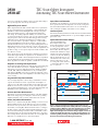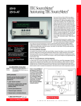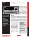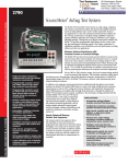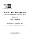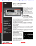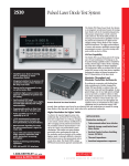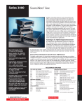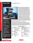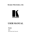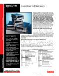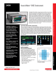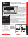
1
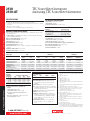
TEC SourceMeter Instrument Autotuning TEC SourceMeter Instrument The Models 2510 and 2510-AT TEC SourceMeter instruments enhance Keithley’s CW (Continuous Wave) test solution for high speed LIV (lightcurrent-voltage) testing of laser diode modules. These 50W bipolar instruments were developed in close cooperation with leading manufacturers of laser diode modules for fiberoptic telecommunications networks. Designed to ensure tight temperature control for the device under test, the Model 2510 was the first in a line of highly specialized instruments created for telecommunications laser diode testing. It brings together Keithley’s expertise in high speed DC sourcing and measurement with the ability to control the operation of a laser diode module’s ThermoElectric Cooler or TEC (sometimes called a Peltier device) accurately. Ordering Information 2510 2510-AT TEC SourceMeter Autotuning TEC SourceMeter Instrument Accessories Supplied User’s Manual, Input/Output Connector Accessories Available 2510-RH 2510-CAB 7007-1 7007-2 KPCI-488LPA KUSB-488B Resistive Heater Adapter for Model 2510 4-Wire Unshielded Cable, Phoenix Connector to Unterminated End Shielded IEEE-488 Cable, 1m (3.3 ft) Shielded IEEE-488 Cable, 2m (6.6 ft) IEEE-488 Interface/Controller for the PCI Bus IEEE-488 USB-to-GPIB Adapter for USB Port Services Available 2510-3Y-EW 1-year factory warranty extended to 3 years from date of shipment 2510-AT-3Y-EW 1-year factory warranty extended to 3 years from date of shipment C/2510-3Y-DATA 3 (Z540-1 compliant) calibrations within 3 years of purchase for Models 2510, 2510-AT* *Not available in all countries The Model 2510‑AT expands the capability of the Model 2510 by offering autotuning capability. P, I, and D (proportional, integral, and derivative) values for closed loop temperature control are determined by the instrument using a modified Zeigler-Nichols algorithm. This eliminates the need for users to determine the optimal values for these coefficients experimentally. In all other respects, the Model 2510 and Model 2510‑AT provide exactly the same set of features and capabilities. The SourceMeter Concept The Model 2510 and Model 2510-AT draw upon Keithley’s unique SourceMeter concept, which combines precision voltage/current sourcing and measurement functions into a single instrument. SourceMeter instruments provide numerous advantages over the use of separate instruments, including lower acquisition and maintenance costs, the need for less rack space, easier system integration and programming, and a broad dynamic range. Part of a Comprehensive LIV Test System In a laser diode CW test stand, the Model 2510 or Model 2510-AT can control the temperature of actively cooled optical components and assemblies (such as laser diode modules) to within ±0.005°C of the user-defined setpoint. During testing, the instrument measures the internal temperature of the laser diode module from any of a variety of temperature sensors, then drives power through the TEC within the laser diode module in order to maintain its temperature at the desired setpoint. Figure 1. The capabilities of the Models 2510 and 2510-AT are intended to complement those of other Keithley instruments often used in laser diode module LIV testing, including the Model 2400 and 2420 SourceMeter instruments, the Model 2502 Dual Photo diode Meter, and the Model 2500INT Integrating Sphere. Trigger Link 2510 or 2510-AT Thermistor Peltier 2400/ 2420 2502 Fiber Computer GPIB 2500INT 1.888.KEITHLEY (U.S. only) w w w.keithley.com A Precision temperature control for TECsSide withText autotuning PID for optimal performance ® G R E A T E R M E A S U R E O F C O N F I D E N C E OPTOELECTRONICS TEST 2510 2510-AT TEC SourceMeter Instrument Autotuning TEC SourceMeter Instrument • 50W TEC Controller combined with DC measurement functions • Fully digital P-I-D control TMAX Max. Initial Slope • Autotuning capability for the thermal control loop (2510-AT) • Designed to control temperature during laser diode module testing • Wide temperature setpoint range (–50°C to +225°C) and high setpoint resolution (±0.001°C) and stability (±0.005°C) • Compatible with a variety of temperature sensor inputs— thermistors, RTDs, and IC sensors • Measures and displays TEC parameters during the control cycle L Autotuning Function The Model 2510‑AT Autotuning TEC SourceMeter instrument offers manufacturers the ability to automatically tune the temperature control loop required for CW testing of optoelectronic components such as laser diode modules and thermo-optic switches. This capability eliminates the need for time-consuming experimentation to determine the optimal P-I-D coefficient values. TS tL Time te Figure 2. Laser Diode TEC Minimum Overshoot 27 26 25 24 • 4-wire open/short lead detection for thermal feedback element 23 • IEEE-488 and RS-232 interfaces • Compact, half-rack design 63% TSTART • Maintains constant temperature, current, voltage, and sensor resistance • AC Ohms measurement function verifies integrity of TEC Active temperature control is very important due to the sensitivity of laser diodes to temperature changes. If the temperature varies, the laser diode’s dominant output wavelength may change, leading to signal overlap and crosstalk problems. Temp Temp (°C) Precision temperature control for TECsSide withText autotuning PID for optimal performance 2510 2510-AT 0 5 10 15 20 25 Time (s) Figure 3. Laser Diode TEC Minimum Settling Time 27 OPTOELECTRONICS TEST Applications Control and production testing of thermoelectric coolers (Peltier devices) in: • Laser diode modules • IR charge-coupled device (CCD) arrays and charge-injection devices (CID) • Cooled photodetectors Temp (°C) 26 25 24 23 0 5 10 15 20 Time (s) Figure 4. The autotuning function offers users a choice of a minimum settling time mode or a minimum overshoot mode, which provides the Model 2510‑AT with the flexibility to be used with a variety of load types and devices. For example, when controlling a large area TEC in a test fixture optimized for P, I, and D values, minimum overshoot protects the devices in the fixture from damage (Figure 3). For temperature setpoints that do not approach the maximum specified temperature for the device under test, the minimum settling time mode can be used to speed up the autotuning function (Figure 4). 50W Output As the complexity of today’s laser diode modules increases, higher power levels are needed in temperature controllers to address the module’s cooling needs during production test. The 50W • Thermal-optic switches • Temperature controlled fixtures 1.888.KEITHLEY (U.S. only) w w w.keithley.com 25 The Model 2510‑AT’s P-I-D Auto-Tune software employs a modified Ziegler-Nichols algorithm to determine the coefficients used to control the P-I-D loop. This algorithm ensures that the final settling perturbations are damped by 25% each cycle of the oscillation. The autotuning process begins with applying a voltage step input to the system being tuned (in open loop mode) and measuring several parameters of the system’s response to this voltage step function. The system’s response to the step function is illustrated in Figure 2. The lag time of the system response, the maximum initial slope, and the TAU [63% (1/e)] response time are measured, then used to generate the Kp (proportional gain constant), Ki (integral gain constant), and Kd (derivative gain constant) coefficients. A G R E A T E R M E A S U R E O F C O N F I D E N C E Open/Short Lead Detection Both models of the instrument use a four-wire measurement method to detect open/short leads on the temperature sensor before testing. Fourwire measurements eliminate lead resistance errors on the measured value, reducing the possibility of false failures or device damage. (5A @ 10V) output allows for higher testing speeds and a wider temperature setpoint range than other, lower-power solutions. High Stability P-I-D Control When compared with other TEC controllers, which use less sophisticated P-I (proportional-integral) loops and hardware control mechanisms, this instrument’s software-based, fully digital P-I-D control provides greater temperature stability and can be easily upgraded with a simple firm ware change. The resulting temperature stability (±0.005°C short term, ±0.01°C long term) allows for very fine control over the output wavelength and optical power of the laser diode module during production testing of DC characteristics. This improved stability gives users higher confidence in measured values, especially for components or sub-assemblies in wavelength multiplexed networks. The derivative component of the instrument’s P-I-D control also reduces the required waiting time between making measurements at various temperature setpoints. The temperature setpoint range of –50°C to +225°C covers most of the test requirements for production testing of cooled optical components and sub-assemblies, with a resolution of ±0.001°C. Interface Options Like all newer Keithley instruments, both models of the instrument include standard IEEE-488 and RS-232 interfaces to speed and simplify system integration and control. Optional Resistive Heater Adapter The Model 2510-RH Resistive Heater Adapter enables either model of the instrument to provide closed loop temperature control for resistive heater elements, rather than for TECs. When the adapter is installed at the instrument’s output terminal, current flows through the resistive heater when the P-I-D loop indicates heating. However, no current will flow to the resistive heater when the temperature loop calls for cooling. The resistive element is cooled through radiation, conducFigure 6. Optional heater adapter tion, or convection. Before the introduction of the Model 2510‑AT, configuring test systems for new module designs and fixtures required the user to determine the best combination of P, I, and D coefficients through trial-and-error experimentation. The Model 2510-AT’s autotuning function uses the modified ZeiglerNichols algorithm to determine the optimal P, I, and D values automatically. Adaptable to Evolving DUT Requirements The Model 2510 and Model 2510-AT are well suited for testing a wide range of laser diode modules because they are compatible with the types of temperature sensors most commonly used in these modules. In addition to 100W, 1kW, 10kW, and 100kW thermistors, they can handle inputs from 100W or 1kW RTDs, and a variety of solid-state temperature sensors. This input flexibility ensures their adaptability as the modules being tested evolve over time. Comparison Data 0.01 2510 Measured Competitor Measured Programmable Setpoints and Limits Users can assign temperature, current, voltage, and thermistor resistance setpoints. The thermistor resistance setpoint feature allows higher correlation of test results with actual performance in the field for laser diode modules because reference resistors are used to control the temperature of the module. Programmable power, current, and temperature limits offer maximum protection against damage to the device under test. 0.005 0 °C -0.005 Accurate Real-Time Measurements Both models can perform real-time measurements on the TEC, including TEC current, voltage drop, power dissipation, and resistance, providing valuable information on the operation of the thermal control system. -0.01 Peltier (TEC) Ohms Measurement TEC devices are easily affected by mechanical damage, such as sheer stress during assembly. The most effective method to test a device for damage after it has been incorporated into a laser diode module is to perform a low-level AC (or reversing DC) ohms measurement. If there is a change in the TEC’s resistance value when compared with the manufacturer’s specification, mechanical damage is indicated. Unlike a standard DC resistance measurement, where the current passing through the device can produce device heating and affect the measured resistance, the reversing DC ohms method does not and allows more accurate measurements. 1.888.KEITHLEY (U.S. only) w w w.keithley.com Precision temperature control for TECsSide withText autotuning PID for optimal performance TEC SourceMeter Instrument Autotuning TEC SourceMeter Instrument -0.015 One Hour Interval Figure 5. This graph compares the Model 2510/2510-AT’s A/D converter resolution and temperature stability with that of a leading competitive instrument. While the competitive instrument uses an analog proportional-integral (P-I) control loop, it displays information in digital format through a low-resolution analog-to-digital converter. In contrast, the Model 2510/2510-AT uses a high-precision digital P-I-D control loop, which provides greater temperature stability, both over the short term (±0.005°C) and the long term (±0.01°C). A G R E A T E R M E A S U R E O F C O N F I D E N C E OPTOELECTRONICS TEST 2510 2510-AT 2510 2510-AT TEC SourceMeter Instrument Autotuning TEC SourceMeter Instrument SPECIFICATIONS TEC Output SPECIFICATIONS OUTPUT RANGE: ±10VDC at up to ±5ADC.15 OUTPUT RIPPLE: <5mV rms9. AC RESISTANCE EXCITATION: ±(9.6mA ± 90µA).14 The Models 2510 and 2510-AT TEC SourceMeter instruments are designed to: • Control the power to the TEC to maintain a constant temperature, current, voltage, or thermistor resistance. • Measure the resistance of the TEC. • Provide greater control and flexibility through a software P-I-D loop. TEC MEASUREMENT SPECIFICATIONS3 Function Operating Resistance 2, 10, 11, 12 Operating Voltage 2,10 Operating Current10 AC Resistance 2, 18 Model 2510, 2510-AT Side Textspecifications CONTROL SYSTEM SPECIFICATIONS SET: Constant Peltier Temperature, Constant Peltier Voltage, Constant Peltier Current. Constant Thermistor Resistance. CONTROL METHOD: Programmable software PID loop. Proportional, Integral, and Derivative gains independently programmable. SETPOINT SHORT TERM STABILITY: ±0.005°C rms1,6,7. SETPOINT LONG TERM STABILITY: ±0.01°C1,6,8. SETPOINT RANGE: –50°C to 225°C. UPPER TEMPERATURE LIMIT: 250°C max. LOWER TEMPERATURE LIMIT: –50°C max. SETPOINT RESOLUTION: ±0.001°C, <±400µV, <±200µA 0.01% of nominal (25°C) thermistor resistance. Hardware Current Limit: 1.0A to 5.25A ±5%. Software Voltage Limit:±0.5 to 10.5V ±5%. OPEN SHORTED THERMOELECTRIC DETECTION LOAD IMPEDANCE: Stable into 1µF typical. COMMON MODE VOLTAGE: 30VDC maximum. COMMON MODE ISOLATION: >109W, <1500pF. MAX. VOLTAGE DROP BETWEEN INPUT/OUTPUT SENSE TERMINALS: 1V. MAX. SENSE LEAD RESISTANCE: 1W for rated accuracy. MAX. Force LEAD RESISTANCE: 0.1W. SENSE INPUT IMPEDANCE: > 400kW. thermal feedback element SPECIFICATIONS3 Sensor Type RTD Excitation13 Nominal Resistance Range Excitation Accuracy1,3 Nominal Sensor Temperature Range Calibration Measurement Accuracy1,3 ±(% rdg + offset) 100 W 2.5 mA 4 V max 0–250 W ±1.5% Thermistor Nominal Thermistor Resistance 100 W 1 kW 10 kW 100 kW Solid State Current Voltage Output (Iss) Output (Vss) +13.5 V 2.5 mA 833 µA 15.75V max 0–2..50 kW ±2.9% 100 W 2.5 mA 8 V max 0–1 kW ±2.9% 1 kW 833 µA 8 V max 0–10 kW ±2.9% 10 kW 100 µA 8 V max 0–80 kW ±2.9% 100 kW 33 µA 6.6 V max 0–200 kW ±2.9% –50° to +250°C –50° to +250°C –50° to +250°C –50° to +250°C –50° to +250°C –50° to +250°C α, β, δ settable α, β, δ settable A, B, C settable A, B, C settable A, B, C settable A, B, C settable Slope & offset Slope & offset 0.04 + 0.07 W2 0.04 + 0.04 W2 0.04 + 0.07 W2 0.04 + 0.4 W2 0.02 + 3 W 0.04 + 21 W 0.03 + 100 nA 0.03 + 500 µV 1 kW 833 µA General Thermistor Measurement Accuracy19 OPTOELECTRONICS TEST 1 Year, 23°C ±5°C ±(2.0% of rdg + 0.1W) ±(0.1% of rdg + 4mV) ±(0.4% of rdg + 8mA) ±(0.10% of rdg + 0.02W) Accuracy vs. Temperature 0°C 25°C 50°C 100°C 0.021°C 0.035°C 0.070°C 0.27°C 0.015°C 0.023°C 0.045°C 0.18°C 0.006°C 0.012°C 0.026°C 0.15°C 0.009°C 0.014°C 0.026°C 0.13°C OPEN/SHORTED ELEMENT DETECTION SOFTWARE LINEARIZATION FOR THERMISTOR AND RTD Common Mode Voltage: 30VDC. Common Mode Isolation: >109W, <1000pF. Max. Voltage Drop Between Input/Output Sense Terminals: 1V. Max. Sense Lead Resistance: 100W for rated accuracy. Sense Input Impedance: >108W. 1.888.KEITHLEY (U.S. only) w w w.keithley.com NPLC Normal 1.00 NMRR 16 60 dB CMRR 17 120 dB1 SOURCE OUTPUT MODES: Fixed DC level. PROGRAMMABILITY: IEEE-488 (SCPI-1995.0), RS-232, 3 user-definable power-up states plus factory default and *RST. POWER SUPPLY: 90V to 260V rms, 50–60Hz, 75W. EMC: Complies with European Union Directive 98/336/EEC (CE marking requirements), FCC part 15 class B, CTSPR 11, IEC 801-2, IEC 801-3, IEC 801-4. VIBRATION: MIL-PRF-28800F Class 3 Random Vibration. WARM-UP: 1 hour to rated accuracies. DIMENSIONS, WEIGHT: 89mm high × 213 mm high × 370mm deep (3½ in × 83 ⁄8 in × 149 ⁄16 in). Bench configuration (with handle and feet): 104mm high × 238mm wide × 370mm deep (41 ⁄8 in × 93 ⁄8 in × 149 ⁄16 in). Net Weight: 3.21kg (7.08 lbs). ENVIRONMENT: Operating: 0°–50°C, 70% R.H. up to 35°C. Derate 3% R.H./°C, 35°–50°C. Storage: –25° to 65°C. A ±2.9% –40° to +100°C NOTES NOISE REJECTION: SPEED ±12% –40° to +100°C G R E A T E R 1. Model 2510 and device under test in a regulated ambient temperature of 25°C. 2. With remote voltage sense. 3. 1 year, 23°C ±5°C. 4. With ILoad = 5A and V Load = 0V. 5. With ILoad = 5A and V Load = 10V. 6. With 10kW thermistor as sensor. 7. Short term stability is defined as 24 hours with Peltier and Model 2510 at 25°C ±0.5°C. 8. Long term stability is defined as 30 days with Peltier and Model 2510 at 25°C ±0.5°C. 9. 10Hz to 10MHz measured at 5A output into a 2W load. 10. Common mode voltage = 0V (meter connect enabled, connects Peltier low output to thermistor measure circuit ground). ±(0.1% of rdg. + 0.1W) with meter connect disabled. 11. Resistance range 0W to 20W for rated accuracy. 12. Current through Peltier > 0.2A. 13. Default values shown, selectable values of 3µA, 10µA, 33µA, 100µA, 833µA, 2.5mA. Note that temperature control performance will degrade at lower c urrents. 14. AC ohms is a dual pulsed measurement using current reversals available over bus only. 15. Settable to <400µV and <200µA in constant V and constant I mode respectively. 16. For line frequency ±0.1%. 17. For 1kW unbalance in LO lead. 18. Resistance range 0W to 100W for rated accuracy. 19. Accuracy figures represent the uncertainty that the Model 2510 may add to the temperature measurement, not including thermistor uncertainty. These accuracy figures are for thermistors with typical A,B,C constants. M E A S U R E O F C O N F I D E N C E