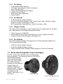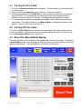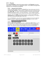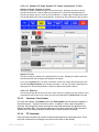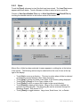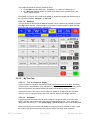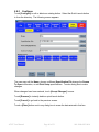
1
Larson Systems Inc.
060-1000-0082-00A
ATST
Automatic Torsion Spring Tester
User Manual
Current for FLASH Software Version 2.39
ATST User Manual
Page 2 of 51
060-1000-0082-00A
About This Manual
This manual could contain technical inaccuracies or typographical errors. Changes are
periodically made to the information contained herein. These changes will be incorporated in
new editions of the manual.
Copyright © 2007 Larson Systems Inc.
All rights reserved. No part of this manual may be reproduced by any means without written
permission of the author, except portions necessary for internal use only by the purchaser of
the LSI system.
ATST User Manual
Page 3 of 51
060-1000-0082-00A
Table Of Contents
1
1.1
INTRODUCTION .................................................................................................................. 6
ATST Standard Features...................................................................................................................................... 7
1.2 FLASH Software Packages.................................................................................................................................. 7
1.2.1 Basic ................................................................................................................................................................. 7
1.2.2 Extra ................................................................................................................................................................. 7
1.2.3 Pro Spring ........................................................................................................................................................ 8
1.2.4 Pro Material...................................................................................................................................................... 8
1.2.5 Fatigue Testing ................................................................................................................................................ 8
1.2.6 Pro Ultimate ..................................................................................................................................................... 8
1.3
Smart Interchangeable Torque Cartridges ....................................................................................................... 8
1.4
Custom Tooling ..................................................................................................................................................... 9
1.5
Universal Tooling .................................................................................................................................................. 9
1.6
Web Service, Network, and Printer Connection .............................................................................................. 9
1.7
Additional Options and Equipment.................................................................................................................... 9
2
USING THE MANUAL........................................................................................................ 10
3
SAFETY AND USE GUIDELINES ..................................................................................... 10
3.1
Important Considerations.................................................................................................................................. 10
3.2
The Safety Shield Enclosure ............................................................................................................................. 10
3.3
Abort Test and Emergency Stop ...................................................................................................................... 10
4
MACHINE SETUP .............................................................................................................. 11
4.1
Turning On The Tester ....................................................................................................................................... 12
4.2
Turning Off The Tester ....................................................................................................................................... 12
4.3 About The Main Default Display ....................................................................................................................... 12
4.3.1 Navigation Toolbar ........................................................................................................................................ 13
4.3.2 The Jog Bar ................................................................................................................................................... 13
4.3.3 Torque vs. Angle Graph ................................................................................................................................ 13
4.3.4 Angle .............................................................................................................................................................. 14
4.3.5 Torque ............................................................................................................................................................ 14
4.3.6 Instructions..................................................................................................................................................... 14
4.3.7 Abort Test....................................................................................................................................................... 14
4.3.8 Clockwise and Counterclockwise Rotation .................................................................................................. 14
5
MAIN MENU APPLICATIONS ........................................................................................... 15
5.1 Manual Mode ........................................................................................................................................................ 15
5.1.1 Using the Angle Display ................................................................................................................................ 15
5.1.2 Using the Torque Display.............................................................................................................................. 17
5.1.3 Run A Basic Test........................................................................................................................................... 18
ATST User Manual
Page 4 of 51
060-1000-0082-00A
5.2 Program Mode ..................................................................................................................................................... 19
5.2.1 New................................................................................................................................................................. 19
5.2.2 Check ............................................................................................................................................................. 19
5.2.3 Program.......................................................................................................................................................... 20
5.2.4 Sorting ............................................................................................................................................................ 26
5.2.5 Preferences (Prefs) ....................................................................................................................................... 29
5.3
Quick Test ............................................................................................................................................................ 30
5.4 File ......................................................................................................................................................................... 31
5.4.1 New................................................................................................................................................................. 31
5.4.2 Open ............................................................................................................................................................... 32
5.4.3 Save ............................................................................................................................................................... 33
5.4.4 Save As… ...................................................................................................................................................... 34
5.5 Automatic Mode .................................................................................................................................................. 34
5.5.1 Using a Predefined Program ........................................................................................................................ 34
5.5.2 Select How Results Are Compiled ............................................................................................................... 35
5.5.3 Viewing Results ............................................................................................................................................. 35
5.5.4 Preferences (Prefs) ....................................................................................................................................... 37
5.5.5 Display Features and Operation................................................................................................................... 38
5.6 Quick Launch....................................................................................................................................................... 39
5.6.1 Launch............................................................................................................................................................ 39
5.6.2 Configure........................................................................................................................................................ 40
5.6.3 Add ................................................................................................................................................................. 41
5.7 FLASH Setup........................................................................................................................................................ 42
5.7.1 Factory ........................................................................................................................................................... 42
5.7.2 Calibration ...................................................................................................................................................... 42
5.7.3 User ................................................................................................................................................................ 43
5.7.4 Print Setup ..................................................................................................................................................... 43
5.7.5 Supervisor ...................................................................................................................................................... 45
5.7.6 Access Operating System............................................................................................................................. 46
6
EXAMPLES OF TEST PROGRAMS.................................................................................. 46
6.1
Single Point Test Sequence .............................................................................................................................. 46
6.2
Multi-Point Test Sequence ................................................................................................................................ 48
7
CARE AND MAINTENANCE ............................................................................................. 49
7.1 Smart Interchangeable Torque Cartridges ..................................................................................................... 49
7.1.1 Lock / Test Position ....................................................................................................................................... 49
7.1.2 Changing Cartridges ..................................................................................................................................... 49
7.1.3 Storing ............................................................................................................................................................ 50
7.2
Calibration, Service and Repair........................................................................................................................ 50
7.3
Touch-Screen Interface...................................................................................................................................... 50
ATST User Manual
Page 5 of 51
060-1000-0082-00A
1
INTRODUCTION
LSI’s Automatic Torsion Spring Tester (ATST) is a highly intuitive motorized torque and angle
testing system. The models available are the ATST 200, ATST 500, and ATST 1000. This
family of testers can be equipped to test a wide assortment of spring types using different
torque capacities. Although designed for and commonly used in spring testing, the ATST can
also be used for most any type of material testing application that requires the measurement of
a combination of torque or angle data.
The ATST Series tester features a versatile full color touch screen interface. Touch the
computer screen to run dynamic torque and angle tests, display results in an easy-to-read
graphical or statistical format, store programs and results, or share data via printed report or
network connection. Use LSI’s custom interchangeable tooling technique to machine tooling
blanks to fit specific testing applications. In addition, the universal tooling assembly available
from LSI allows the testing of many parts and requires very little setup time. The custom and
universal tooling assemblies can be changed over in seconds while maintaining repeatability
and reproducibility.
This is truly a full-feature tester. From basic test sequence functionality to the most complex,
programs may be customized and used for numerous applications. Note that features do vary
by model and the level of software purchased.
Test parts as large as 8” in diameter and
up to 12” long on the standard model. The
ATST can be customized to accommodate
much longer capacities if needed.
ATST User Manual
Page 6 of 51
060-1000-0082-00A
This section briefly describes features and options available for the ATST currently in
production. For additional information including torque and angle specifications, pricing on
other products and upgrades available see the LSI website at www.larsonsystems.com.
1.1 ATST Standard Features
•
•
•
•
•
•
•
•
•
•
•
•
•
•
•
FLASH Basic software package
Touch screen controls
Windows XP operating system
Automated or manual testing
Deflection compensation
Absolute zeroing
Rapid changeovers
On-screen and remote abort / cycle controls
Fully enclosed safety shield
Mechanical torque overload stops
Software torque limits
Emergency stop button
English or metric unit selection
Digital calibration
NIST traceable certificate of calibration
1.2 FLASH Software Packages
The Basic software package is standard on an ATST. The Extra, Pro Spring, Pro Material,
and Pro Ultimate are optional software packages. An ATST is programmed with one of
these software packages as specified at purchase. The Fatigue Testing software package
is also optional, but may be purchased in addition to any of the first four software packages
listed and is included with the Pro Ultimate software package. The features of each
software package are described in this section.
1.2.1
•
•
•
•
•
•
•
Single Load Cell Operation
Absolute Programming Only
Up to 2-point Testing
Program Mode, Manual Mode, Automatic Mode, and FLASH Setup
Two Test Point Commands: Torque @Angle, Angle @Torque
No Graphic or Statistical Displays, No Printing Functionality
No Program Saving or Retrieving
1.2.2
•
•
•
•
•
•
•
Basic
Extra
FLASH Basic Software Features
Dual Interchangeable Load Cell Operation
Absolute and Incremental Programming
Up to 10-point Testing
Additional Test Point Commands: Preset, Free Angle, and Rate
Report Printing Capability and Program Saving / Retrieving
No Graphic or Statistical Results Displays
ATST User Manual
Page 7 of 51
060-1000-0082-00A
1.2.3
•
•
•
•
•
•
•
FLASH Extra Software Features
Full Range Interchangeable Load Cell Operation
Up to 99-point Testing
Graphic and Statistical Results Displays
Length and Force Offsets
Quick Launch Menu Application
Sorting Feature
1.2.4
•
•
•
Pro Spring
Pro Material
FLASH Pro Spring Software Features
Test Point Commands Available: Peak Torque, Pause, Delay, Dynamic to Angle,
Dynamic to Torque, and Dynamic to Time
No Torque @Angle, Angle @Torque, Preset, Free Angle, or Rate
1.2.5
Fatigue Testing
This feature tests the endurance of a part and monitors force performance for the entire
test. Other features of the Fatigue testing option include:
•
•
•
Preset Cycles up to 10,000,000
Archive Data During Cycling at Preset Intervals to a File Viewable via Intranet
Program Testing to Stop at Fatigue or Breakage Point
1.2.6
Pro Ultimate
This FLASH software package is the highest end, full feature package available from
LSI for automated parts testing.
•
•
•
FLASH Pro Spring Software Features
FLASH Pro Material Software Features
Fatigue Testing Software Package Adding Fatigue as a Test Point Command
1.3 Smart Interchangeable Torque Cartridges
All ATST models can be purchased with interchangeable
load cell capability. This requires a minimum of the FLASH
Extra software package
which supports dual load
cells or any of the FLASH
Pro software packages
allowing up to the maximum
number of load cell
capacities offered for a
particular model. Changing
out load cells is very easy
and takes just a few
minutes. See section 7.1 for
Torque Cartridge
instructions.
Torque Cartridge with Lock
ATST User Manual
Page 8 of 51
060-1000-0082-00A
1.4 Custom Tooling
Machine tooling blanks to fit specific applications to achieve repeatable, standardized
setups resulting in user independent reliability. If preferred
send the specifications to LSI and have them made.
1.5 Universal Tooling
The universal tooling assembly available from LSI can be configured to test many parts
without attaching any other fixtures. This assembly includes 2”, 3”, and 4” universal
fixtures, a chuck, a mandrill set to 17/32” diameter and a reaction plate.
Reaction
Plate
Catch Pins
Chuck Fixture
1.6 Web Service, Network, and Printer Connection
These features are set up through the Access Operation System option located under
FLASH Setup. The Operating System is password protected. See section 5.7.6 about
gaining access. The web and network service will need to be set up by an IT Technician
on the tester location end and coordinated with LSI to establish. Contact LSI for details.
1.7 Additional Options and Equipment
•
•
•
•
•
•
Inkjet Printer; connect to tester for reports, includes USB cable
Power Options; 240 VAC, 50 Hz; FLASH 25 - 240 VAC, 60Hz
Sorting Packages; 3 or 5-way can be ordered with automation interface port
Custom Tooling Blanks; for use with custom tooling fixture
Vibration Damping Pad; reduce potential vibration interference for greater
accuracy
Fixtures; custom or universal tooling fixtures, grip set attachment
See www.larsonsystems.com for details about these and other options.
ATST User Manual
Page 9 of 51
060-1000-0082-00A
2
USING THE MANUAL
Have the Automatic Torsion Spring Tester accessible while following along with this manual.
• Be sure to read the Safety and Use Guidelines in section 3 before starting.
• Instruction for basic operation begins at section 4 – Machine Setup. Familiarity with this
section will instill proper use of the interactive touch screen and make the more complex
screens that follow easy to learn.
• Any instruction in brackets and bold type refers to a button on the screen.
• Main menu applications are described in section 5 starting with the easiest.
• Section 6 – Examples of Test Programs leads the operator through programming, saving a
program, running a test, and viewing results. Items learned in separate sections are put
together in a usable sequence for a practical application.
• Know the specifics about the configuration of the ATST purchased, as some sections of
this manual may not apply. Note the model of tester and level of software on the ATST to
determine.
3
SAFETY AND USE GUIDELINES
3.1 Important Considerations
•
•
•
•
•
•
•
•
•
Wound torsion springs have stored potential energy proportional to the spring
constant. Use care and release this energy in a controlled manner to avoid injury.
Do not apply a force greater than the tester is designed for.
Be sure the operating area is clean and dry.
All parts to be tested should be free of oil and contaminants.
Keep the tester from contact with liquid.
This User Manual should be kept available for quick reference.
The safety shield enclosure must be kept closed during testing.
Use of protective eyewear is recommended for safety.
Follow all instructions and warnings related to the use of the FLASH equipped ATST.
3.2 The Safety Shield Enclosure
Each ATST is equipped with a fully enclosed testing area with safety interlock. This safety
shield is designed as a door or cover on the tester protecting the operator from injury if
parts should fly out from the testing area as torque is applied. An error message or
warning displays if not securely closed when using the tester. DO NOT TAMPER WITH,
REMOVE, OR MODIFY THE SAFETY SHIELD or the tester’s warranty shall be void.
3.3 Abort Test and Emergency Stop
The red [Abort Test] button located in the lower right of the display is the first means of
stopping reaction plate movement instantly in an emergency situation. The Emergency
Stop button clearly identified on the front of the ATST is also designed for use in an
emergency, but not to be used frequently for shut down. For powering down under
normal operating conditions, Windows must be properly exited first by touching the red
[Shut Down] button in the upper right of the display screen. A prompt will appear to verify.
Touch [Yes] to continue shutdown. A message says, “Windows is shutting down”. The
screen will display the Windows logo and the message, “It is now safe to turn off your
computer.” The Emergency Stop button may now be pushed to turn off the tester. Using
the Emergency Stop button by itself repeatedly for normal shutdown will likely result in OS
data corruption.
ATST User Manual
Page 10 of 51
060-1000-0082-00A
4
MACHINE SETUP
Place the tester on a level and stable work area where the user can test parts in a comfortable
manner. The tester should be at a height to allow ease in loading, testing and removing parts
from the testing area. The operator should also be able to easily view and access the display.
Adjust its position using a 3/16” allen wrench. Make sure the display fixture is supported while
positioning and tighten when done.
Touch-screen
Interface
Reaction Plate or
Other Tooling
Load Cell is Housed
Inside Affixed to the
Reaction Plate
Tooling
Safety Shield
Tailstock
Power
On
Carriage
Stop
Emergency
Stop
Carriage Lock
Safety Shield
Release
Remote Abort / Cycle
Control
ATST User Manual
Page 11 of 51
060-1000-0082-00A
4.1 Turning On The Tester
1. Turn the red Emergency Stop button clockwise. The knob pops out to allow the tester
to receive power.
2. Next, push the blue Power On button to start up. Windows is loading.
3. A dialog box appears with “FLASH User” in the first box and a blank box for password
entry just below. It is not necessary to enter a password unless password entry is
desired to setup the machine for testing. This feature may be enabled as needed.
4. To continue without entering a password, touch [OK]. The FLASH testing software is
now loading. The display defaults to the Manual Mode as highlighted in yellow on the
display. See the screen shot in section 4.3.7.
4.2 Turning Off The Tester
Touch the red [Shut Down] button located in the upper right of the display when ready to
turn off the machine. Windows will close and a prompt will appear when it is okay to push
in the red Emergency Stop button to power off.
4.3 About The Main Default Display
The screen pictured is the first display that appears after turning on the tester. The tester is
in Manual Mode ready to set the angle to a zero point prior to performing basic torsion and
angle test applications. The tester defaults to Clockwise (CW) rotation.
ATST User Manual
Page 12 of 51
060-1000-0082-00A
This section describes the various features of the Manual Mode screen. See section 5.1
for instructional detail for the use of these features.
4.3.1
Navigation Toolbar
The FLASH software has up to seven Main Menu Applications accessible from the
Navigation Toolbar at the top of every screen: File, Quick Test (not available on
current ATST version), Program Mode, Manual Mode, Automatic Mode, FLASH
Setup and Quick Launch. Not all of the software packages include all application
features. For example, the Basic software package does not include the Quick
Launch, Program Saving and Retrieving (part of File), and Sorting feature (part of
Program Mode). See section 1.2 for additional information about the various software
packages that may be purchased.
4.3.2
The Jog Bar
The Jog Bar located on the left side of the display manually controls the movement of
the fixture in a clockwise (CW) or counterclockwise (CCW) direction. Touch and hold
anywhere on the Jog Bar to engage. The fixture moves faster when the darker portion
of the jog bar is touched and slower when the lighter portion is touched
and stops when the Jog Bar is released. Let the platform stop before
changing directions.
4.3.3
Torque vs. Angle Graph
This time-sensitive graph indicates the current torque and angle and
real time test results. A single point identified by a red dot represents
the degrees the part has been turned and the torque being applied.
ATST User Manual
Page 13 of 51
060-1000-0082-00A
4.3.4
Angle
The Angle display is located on the right just
below the Navigation Toolbar. Its main
function is to show real time angle
measurement. The Go To button rotates the
fixture to a specific angle for a basic test that
gives the resulting torque in real time.
4.3.5
Torque
The Torque display is located on the right just
below the Angle display. Its main function is
to show real time torque. The Go To button
rotates the fixture to a target amount of torque
and gives a resulting angle measurement.
4.3.6
Instructions
The Instructions block at the
bottom of the display gives
helpful directions and information
on how to proceed. This block
may also tell the user what the
tester is doing. Image shown is
blank.
4.3.7
Abort Test
When the fixture is in automatic movement
initiated by running a test or a Go To command,
touching the red [Abort Test] button located in
the lower right of the display will instantly halt the
rotation of the fixture. Its is intended for use in
emergency situations ahead of the emergency
stop button.
4.3.8
Clockwise and Counterclockwise Rotation
Change rotation direction for testing by touching the CW button in the Torque
display that is shown above in section 4.3.5. The button will change to CCW
and the arrow changes direction. See section 5.1.2 for more information on
changing the direction of a test application.
The direction of testing is from the point of view from the Tailstock looking towards the
Reaction Plate or Load Cell. This determinates the rotation of the tooling fixture and
which direction the part / spring is being turned from that perspective.
ATST User Manual
Page 14 of 51
060-1000-0082-00A
5
MAIN MENU APPLICATIONS
These are the seven Main Menu Applications that may be accessed from the Navigation
Toolbar at the top of the display depending on the software package purchased:
•
•
•
•
•
•
•
File – Clear all current specifications and result data, open a file from storage to run a test
or view results, save a programmed test, or rename a file.
Quick Test – Not available on the ATST.
Program Mode – Create and customize a variety of test applications, save and use as
needed. No need to create a test each time for the same application.
Manual Mode – Control the fixture rotation manually using the Jog Bar or [Go To]. Use
[Go To] for basic torque and angle tests and view the results.
Automatic Mode – Run test applications repetitively and generate results in various
formats to be shared or printed in hard copy.
FLASH Setup – Enter basic settings and preferences. The User and Print Setup menus
contain default settings from the factory. Review before testing and change if needed.
Quick Launch – Select and run pre-programmed test applications. Touch two buttons and
be ready to test. Note: User must add the launch buttons to the menu.
The use of each menu item listed above is described in this section. Note that these menu
items are not covered in the order listed above or the order that appears on the Navigation
Toolbar. While each is described individually, the menu applications are usually used in
conjunction with each other. For example: after creating a test sequence in the Program
Mode the user may go to Automatic Mode to run the test, then save the information gathered
using File, or vice versa.
5.1 Manual Mode
The tester defaults to Manual Mode when turned on. The user is able to manually control
the rotation of the chuck or custom-tooling fixture. Test results are displayed as real time
torque and angle data, both in numerical and graphical form.
5.1.1
Using the Angle Display
“Home Tester” appears in the value / text
box at every startup. Set the Angle Zero
Point to clear the message.
Set Angle Zero Point
1. Make sure the testing area between the
reaction plate and the fixture is clear of
any parts or materials.
2. Position the tooling (Universal or Custom) manually at a point chosen for zeroing.
3. Touch [Zero] on the left below the dialog box. This initializes the tester and sets the
angle to zero.
Once the Angle Zero Point is set, it does not need to be done again until the next
startup. However, when testing different parts that require beginning the rotation from a
different point, just touch [Zero] to set a new zero point as needed.
ATST User Manual
Page 15 of 51
060-1000-0082-00A
The [Go To] Function:
Touch [Go To] for automatic rotation of the chuck fixture to a specified angle without
programming a test. A numeric keypad appears with a dialog box. Enter the desired
angle of the fixture by touching the keypad and touch the green [Go To] button. The
fixture rotates to the degree of turn (angle) specified. The Torque vs. Angle graph
adjusts accordingly in real time.
Unit of Measurement Selection:
The button just below [Go To] may read [deg] or [rev]. Touch this button to select
either inches or millimeters as the unit of measurement for length. The current program
or results displayed will automatically convert to the unit of measurement selected.
The Zero, Reset, and Offset Buttons:
[Zero] – set the current angle reading to zero without setting an angle offset. This
feature allows resetting the zero as needed during testing.
[Reset] – return the zero point to the setting established when the Angle Zero Point was
originally set during tester initialization.
[Offset] – program an angle-offset point to compensate for fixtures installed after the
Angle Zero Point has been set. A numeric keypad appears with a dialog box. Touch
the buttons on the keypad to enter the desired angle offset value and touch [Enter] to
set. This shifts the zero angle point by the specified number of degrees.
How to Change Test Speed
Above the dialog box in the Angle display is a turtle icon before a dark gray percentage
bar that reads 100% followed by a rabbit icon as shown in the first example below. This
speed percentage bar controls the rotational testing speed. Touch the turtle icon to
decrease the fixture rotation speed or the rabbit icon to increase. When the percentage
bar is below 100% it turns red as shown in the second example:
The testing speed will stay at the speed designated until changed again in either
Manual Mode or Automatic Mode, or preset in FLASH Setup under User – Max
Platform Speed. See the User settings for speed shown below. When the tester is
turned off it defaults back to the 100% setting.
There is also a User setting % Speed Increment Amount that controls how much the
percentage changes when the turtle or rabbit is touched.
% of Max Speed of First Test is a feature where the speed percentage can be set to a
reduced speed for the first test of a part, i.e. when Automatic Mode is entered and
there are no results shown. This initial test percentage is controlled from the User
menu under the FLASH Setup screen. A portion of the screen this that controls the
speed settings is shown below. Just touch the Setting Value box to make changes.
Touch the scroll bar along the right side to navigate.
ATST User Manual
Page 16 of 51
060-1000-0082-00A
5.1.2
Using the Torque Display
The Torque display is located on the right just below the Angle display. Its main
function is to show real time torque.
The [Go To] Function:
Touch [Go To] for smooth automatic rotation of
the fixture to apply a specific amount of torque
without programming a test. Touch the buttons
on the on-screen keypad to enter the target
torque value and touch the green [Go To]
button. The fixture will automatically begin
applying torque to the part being tested until it
reaches the target value. The Torque vs. Angle
graph adjusts accordingly in real time.
Unit of Measurement Selection:
The button just below [Go To] may read [in-lb], [N-mm], [g-mm], [kg-mm], [in-oz], [ftlb], [N-M], [kg-M], or [kg-cm]. Touch this button to select the unit of measurement for
torque. The current program and results displayed will automatically convert to the unit
of measurement selected.
The Zero, Reset, and Offset Buttons:
[Zero] – Set the current torque reading to zero without specifying a torque offset.
[Reset] – Clear out the zero value if [Zero] was touched and not intended.
[Offset] – Enter the torque offset needed to compensate for the weight of any fixtures
attached to the reaction plate (i.e. load cell) prior to testing. A numeric keypad appears
with a dialog box when the [Offset] button is touched. Touch the buttons on the keypad
to enter the desired torque offset value and touch [Enter] to set. This adjusts the zero
torque starting point.
Direction of Test:
On the Torque display, the current direction of testing, Clockwise or Counterclockwise
is indicated by CW or CCW with a red arrow. To change direction touch the CW / CCW
indicator. The tester will remain in the selected direction for testing until changed back
or tester is turned off. The default setting is Clockwise (CW).
The direction can also be selected from [Program Mode] by choosing Clockwise or
Counterclockwise just below the Test Point box. In addition, the [Prefs] screen under
the Program Mode also has a directional selection button.
ATST User Manual
Page 17 of 51
060-1000-0082-00A
5.1.3
Run A Basic Test
The Angle Zero Point should have been set at startup as described in section 5.1.1.
However, a different Angle Zero Point may be chosen if needed by positioning the
chuck fixture mechanism as desired and touching [Zero] in the Angle display.
Setup of Tester:
1. Move the fixture to the desired distance from the reaction plate and secure using the
Carriage Lock. (Carriage Stop should be positioned at a point to prevent the
carriage from moving towards the Reaction Plate and damaging parts or tooling.)
2. Rotate the fixture to the desired position using the Jog Bar so a spring or part may
be mounted and tested. Be sure to touch [Zero] in the Angle display to set the
starting point.
3. Open the enclosure and attach the part being tested to the fixtures. Close and
secure the enclosure.
Perform either Torque @ Angle or Angle @ Torque described next after completing.
Torque @ Angle:
1. Touch [Zero] in the Torque display to remove the part weight from the reading.
2. Touch [Go To] in the Angle display. Enter the desired Angle value (degree of turn)
on the keypad that the chuck fixture should move for torque measurement and touch
the green [Go To] button.
The tooling fixture immediately rotates to the specified angle and takes a measurement
that appears in the Torque display. This Torque @ Angle measurement is also
reflected on the graph by the position of the red dot. The tooling fixture will remain at
this position until a new “go to” command is given or until moved manually using the
Jog Bar in Manual Mode.
Angle @ Torque:
1. Touch [Zero] in the Torque display to eliminate the part weight from the reading.
2. Touch [Go To] in the Torque display. Enter the torque value on the keypad that the
chuck assembly should apply and touch the green [Go To] button.
The tooling fixture slowly applies torque to the part and reduces speed as is reaches its
destination torque value. The angle measurement appears in the dialog box of the
Angle display and the position of the red dot on the graph adjusts accordingly. Again,
the fixture will remain at this position until a new “go to” command is given or moved
manually using the Jog Bar.
In either scenario, the [Go To] command may be changed to a new specified torque or
angle as many times as the user would like. Adjustments to angle can be made using
the Jog Bar to fine-tune a measurement. In addition, the units of measurement or
speed of testing may be changed.
ATST User Manual
Page 18 of 51
060-1000-0082-00A
5.2 Program Mode
Touch [Program Mode] on the Navigation Toolbar to start. Use this screen to create a
variety of customized testing sequences, set test preferences and define sorting criteria.
There are five sub-screens in the Program Mode: New, Check, Program, Sorting, and
Preferences (Prefs). The [Program] sub-screen is usually the main screen to work from.
Note: The Sorting sub-screen feature is not available with the Basic or Extra software
packages. See section 1.2 for additional information about the software packages.
5.2.1
New
Touch [New] to clear all specifications and results. A message will appear to verify the
action. Touch [Yes] to clear and continue or [No] to cancel the action. Any test points,
preferences, and sorting criteria that have been entered will be cleared if [Yes] is
selected. This includes any results that were obtained.
5.2.2
Check
Touch [Check] to check for any errors when creating a test point sequence. If the
sequence contains any errors, a message box will appear and identify the problem.
Touch [OK] to exit the message box.
The Test Point screen moves to the test point that contains the error. Make the
correction and check the sequence again when satisfied. The message box will
indicate when the sequence is good and contains no errors. Touch [OK] to clear the
message box and continue.
Touch to Change
Test Direction
ATST User Manual
Page 19 of 51
060-1000-0082-00A
5.2.3
Program
When [Program Mode] is selected the display defaults to the [Program] sub-screen
shown above. The selections are highlighted in yellow. This is where a test application
sequence can be defined and programmed.
5.2.3.1
Using the Test Point Box
Initially, the screen displays a gray box titled End Of Test. Above this box and to the left is
a gray box titled “Test Point”. Scroll through the available test points by touching the arrow
keys, [!] or ["]. The number of test points available for a sequence varies by software
package purchased (see section 1.2 for more information). To go to a specific test point,
touch the value dialog box and enter the desired test point number using the keypad that is
displayed. As the arrow ["] is touched from test point 1, if each test point displays the
“End Of Test” box, no commands have been entered for a test sequence yet. To create a
new Test Point sequence always begin at Test Point 1.
From the Test Point box, test points may be inserted or deleted as a test point application
sequence is created. Instructions for using [Insert] and [Delete] are found in section
5.2.3.6 – Creating a Test Point Application Sequence.
5.2.3.2
Select New Commands
Each time [Select New Command] is touched in a Command or End Of Test box, a gray
bar or box with up to 14 black command buttons appears in the center of the display as
shown below. When this selection bar is displayed, the buttons in the Test Point box are
inactive. This means the test point number displayed is in process of being created.
ATST User Manual
Page 20 of 51
060-1000-0082-00A
The Test Point Command selection bar appears in the center of the display as shown above
with the Pro Ultimate software package offering 14 available commands. See section 1.2
for feature availability.
Choose test commands from this bar when creating a test sequence application. As a
command is touched, a new gray box appears with the name of the command at the top as
shown below. In each command box select absolute or incremental testing and enter the
required test-point data in any highlighted value dialog box on the screen. Touch the right
arrow key in the Test Point box to go to the next test point. Touch [Select New Command]
to add the next test point command to the test sequence. Repeat this process until the test
sequence desired is complete. For the last test point, choose [End Test].
Absolute or Incremental Testing:
Certain commands can be performed in Absolute or Incremental mode. In Absolute mode,
the torque and angle (both specifications and results) reference a fixed zero point. In
Incremental mode, the torques, angles, and results are given as deflection amounts. There
is an option available that specifies that the results of incremental testing be given as
absolute measurements and is covered in section 5.2.5.4.
Test Commands:
The subsections that follow describe each possible command for the FLASH. Numerical
values must be entered for many of the commands before moving to the next test point.
However, some commands may not require any values, but will allow the user to enter
optional data if desired. Text boxes that require entry are labeled and highlighted. Optional
text boxes for data are labeled, but not highlighted. Enter data by touching a text box to
activate an on-screen keypad. Results from entering a nominal value calculate a
percentage representing the distance of the measurement taken from that nominal value.
ATST User Manual
Page 21 of 51
060-1000-0082-00A
An optional tolerance value may be entered. Tolerance is entered as a percentage from
0.01% to 99.99% or a specific upper or lower limit (USL or LSL). Either way it is entered,
the other method is automatically calculated and filled when results are displayed. For
example, if a tolerance percentage is entered, the USL and LSL are automatically
calculated. The test point is “conditional” when using a tolerance value to obtain test data.
By specifying the speed, the test point being programmed may be performed at a different
speed than other test points. The value entered is the maximum speed the chuck fixture
may rotate during the test. All fixture rotation starts at a slow speed and gradually increases
to maximum speed. Depending on the distance from the starting point to the test point
target, the maximum speed (by default or as specified) may not always be reached. If this
option is left blank the default speed is a maximum revolution speed of 90 revs per minute.
5.2.3.2.1
Torque @ Angle
The fixture will rotate to the specified angle and the torque measurement is the result. Torque at
Angle tests can be performed in either Absolute or Incremental mode and requires an angle
value. Test speed, nominal
torque and tolerance values
are optional.
5.2.3.2.2
Angle @
Torque
The fixture will rotate in the
direction specified and apply
the torque value entered and
the angle measurement (degree of turn) is the result. Angle At Torque tests can be performed
in either Absolute or Incremental mode and require a target torque value. Test speed, nominal
angle and tolerance values are optional.
5.2.3.2.3
Preset
The fixture will rotate to either specified angle or to a target torque value. The fixture then returns
to its start point. This sequence will be repeated a specific number of times up to a maximum of
50. There are no results for a Preset test. Choose Absolute or Incremental mode and enter a
torque or an angle specification. Specifying a different test speed is optional.
5.2.3.2.4
Free Angle
Free Angle: The fixture will rotate clockwise so torque is very slightly applied to measure the
free angle of the part. There are no required specifications to be entered. Test speed, nominal
torque and tolerance values are optional.
5.2.3.2.5
Peak Torque
The fixture will rotate to the specified angle. The maximum force encountered during the rotation
is the result. A target angle value is required. Nominal torque and tolerance values are optional.
The test speed defaults to 90 rpm when measuring Peak Torque and can be changed.
5.2.3.2.6
Rate
Rate is defined as the difference between two test points divided by the distance (angle
movement) between. Two test points are required in the sequence before Rate is selected.
These two test points are required data so the Rate is calculated based on the correct test points.
Nominal rate and tolerance values are optional.
5.2.3.2.7
Cancel
Touch [Cancel] to reverse the screen displayed back to the previous screen / menu displayed.
ATST User Manual
Page 22 of 51
060-1000-0082-00A
5.2.3.2.8
Pause
The test sequence stops until manually resumed by the operator. To use this command, touch
[Pause], then touch the right arrow to move to the next test point, then touch [Select New
Command] to choose the next command that will be performed when the test is resumed. When
a Pause test point is reached during a test sequence, testing stops. The [Resume] button is now
active. Touch [Resume] when ready to continue testing.
5.2.3.2.9
Delay
The test sequence stops for a specified amount of time and then resumes testing automatically
when the time specified expires. To use this command, touch [Delay] and enter the amount of
time delay desired. Be sure this command is placed correctly in the test command sequence.
Touch the right arrow to go to the next test point, then touch [Select New Command] to choose
the next command.
5.2.3.2.10 Fatigue (Optional Feature)
This feature is a separately purchased item. If not purchased, [Fatigue] is not an available Test
Command selection.
Fatigue testing requires a nominal torque or angle value entered as the target position. When
this command is selected, choose Incremental or Absolute testing, then specify Fatigue to Angle
or Fatigue to Torque for the test. Enter the nominal torque or angle value as applicable and the
number of cycle counts desired – the maximum number of cycles allowed is 10,000,000.
The fatigue test can be programmed to stop in the event of part fatigue or breakage. By entering
a nominal torque or angle and a tolerance value the part is checked when the fixture stops at the
target position. If the part does not test within the specified tolerance, the Fatigue test will stop.
When the fixture reaches its target position, the resulting value may be archived and analyzed
further at another time. If archiving data is selected an archive interval can be set to control how
th
much data is archived and how often. The frequency may be set to every cycle, every 10 cycle,
th
every 50 cycle, etc. The data is stored in a file (.csv) that spreadsheet programs can read. The
FLASH only stores the data to a file and does not analyze or report the test data in any way.
ATST User Manual
Page 23 of 51
060-1000-0082-00A
5.2.3.2.11 Dynamic To Angle, Dynamic To Torque, and Dynamic To Time
Dynamic To Angle / Dynamic to Torque
The fixture moves to a specified angle or a specified torque. Readings are taken at the set
intervals specified as the fixture rotates to the target point. Results are displayed based on
interval type (angle, torque, or time) and interval amount. A target angle or target torque value
must be specified for the interval type selected. Specifying an interval amount is also required.
Dynamic To Time
The fixture remains in position for a specified amount of time. Readings are taken at the time
intervals specified until the target time specified has expired.
In any of the “Dynamic To” Test Point Commands, a user may change the Interval type in the
box titled Test Specifications by touching the selection. The user may enter a starting and an
ending point for interval measurement or specify a different test speed if desired.
5.2.3.2.12 End Test
This command specifies the end of the test. When a test is in progress, the first instance of this
command will end the test, even if there are valid commands after the End Of Test command.
5.2.3.3
Customer / Part Number
For each test created, a Customer name and Part Number can be entered to appear on
the printed report. Touch the text box to enter. In addition, when a stored program is
retrieved, the retrieved file name would be on the printed report and also appear on the
display just below File. If the test program has not yet been saved and a Part Number is
entered, the Part Number defaults as the filename unless manually changed.
5.2.3.4
TP Comments
Each individual test point can contain comments that appear on the printed report. Enter
test point comments by touching the text box at the bottom of the display.
ATST User Manual
Page 24 of 51
060-1000-0082-00A
If creating a test point sequence by selecting the test point commands, each test point will
already be labeled as the test point command on the printed report under test specifications.
Any comment entered will appear below the labeled test point. To view how this would
appear in a printed report, see Preview in section 5.2.3.5.
5.2.3.5
Print Report
Generate a hard copy of the program and any results obtained. When [Print Report] is
touched, a message box to confirm appears. The options are Print, Preview, or Cancel.
The Preview function can be used even if a printer is not connected to the tester. Viewing
what the printed report would look like may be helpful to determine relevance of results, the
best viewing format, if the printout needs to be modified, etc. Results can be saved and
printed or viewed in the format desired at a later time. Report printout specifications may
also be modified in FLASH Setup > Print Setup. When viewing a report in Preview:
•
•
•
Scroll through the pages using arrows along the side or bottom of page
Use [Zoom] to zoom in or out to view by page or enlarge
Touch [Close Preview] to exit Preview
5.2.3.6
Creating a Test Point Application Sequence
Before creating a test point application sequence go to [Prefs] to view the default settings
and make any necessary changes. (See section 5.2.5). Touch [Program] to return.
The End Of Test box should be displayed and the Test Point value box should be at 1.
1. Touch [Select New Command] in the End Of Test box. The Test Command selection
bar appears:
2. Touch the desired Test Command. A box appears titled with the command selected.
(Ex/ Command : Torque @ Angle)
3. In the command box choose Incremental or Absolute measurement. Choice is
identified by a small green square. The box includes a description of what the machine
does with this command. Value boxes on the screen are waiting for data to be entered.
4. To enter required data, touch the value box and a keypad will appear. Touch the
desired numbers. When finished, touch [Enter].
5. TP Comments may be entered that will appear on the printed report. Touch the TP
Comment dialog box at the bottom of the screen and an alphanumeric keypad appears.
Type in a comment by touching the letters on the keypad and touching [Enter].
6. When finished or if no data is required, touch the right arrow button in the Test Point box
to move to the next Test Point. The End Of Test box appears.
7. To add more Test Point commands, repeat from step 1.
8. When the last Test Point command has been entered and the End Of Test box is
displayed the test application sequence is complete.
9. Touch [Check] to check for test point errors.
5.2.3.6.1
Insert a Test Point
First, a command box must be displayed to use the Test Point box. Navigate using the right or
left arrow to view the test point in a sequence where a new test point will be inserted. The test
point being viewed will move ahead one point to follow the inserted test point.
1.
2.
3.
4.
5.
6.
7.
Touch [Insert] when viewing the test point.
Any test points already set at and above this point will shift up one.
The current test point is left blank and ready for a new test command.
Touch [Select New Command] to continue.
Choose the desired command from the Test Command selection bar to insert.
Enter any required or optional data, including TP Comments.
Navigate as needed to make changes to the test application sequence or go to the End of
Test, Check and continue.
ATST User Manual
Page 25 of 51
060-1000-0082-00A
5.2.3.6.2
Delete a Test Point
Touch [Delete] to delete the test point being viewed. Any test points above the one deleted shift
down by one in the sequence.
These features allow easily customizing the data measured during a test sequence and
positioning the order of the commands as needed.
5.2.4
Sorting
Sorting is not available with the Basic and Extra software packages. (See section 1.2.)
When test points are programmed with conditions by entering Nominal and Tolerance
values during, the results can be used to sort parts into categories. The FLASH tester
can also send electronic signals to other machines for sorting purposes such as sorting
chutes or PLC controllers.
This section describes the items displayed on this screen and their use. Practical
application examples follow for setting up a condition and output table for sorting.
5.2.4.1
Condition and Output Table
On the left side of the display is a Condition and Output Table used to enter conditions for
sorting parts and defining the resulting output. The table is navigated starting from the first
row and continuing until a true condition is met or to the end of the table. The current row
being defined is highlighted in blue. To edit, just touch the row to be changed.
5.2.4.2
Check Test Point
The Check Test Point section of the display allows the user to define a condition for each
test point. Initially, the value dialog box will be empty. To select and work with a test point,
ATST User Manual
Page 26 of 51
060-1000-0082-00A
touch the value dialog box. Touch the number of the desired test point on the keypad and
enter. Once a test point is selected, choose from the six possible conditions listed.
Touch the condition for the test point displayed. The entry of the condition is controlled by
the Accept Changes for Row X button on the right side of the display.
As a condition is chosen, the box above this button displays the condition selected. To
confirm the selection, touch [Accept Changes for Row X]. The condition selected for that
test point is now displayed in the row highlighted on the Condition and Output Table.
5.2.4.3
Open Flap
The Open Flap section allows the selection of an output flap for a test point condition.
Touch a flap selection from those listed to represent the category of a condition for sorting.
An electronic signal is sent to a sorting device for the flap selected. As an output is selected
for a test point condition, the box above the Accept Changes for Row X button reflects the
output selected. To confirm the selection, touch [Accept Changes for Row X]. The output
is displayed in the current row of the Condition and Output Table.
5.2.4.4
Options
This section of the display contains three options to be set for sorting purposes: Default
Flap, Sweep / EOT Time (s), and Flap Open Time.
5.2.4.4.1
Default Flap
If the sorting table is traversed during a test point sequence and no true statement is found, a flap
may be set to activate as a default mechanism. The Default Flap setting is Flap 0, resulting in no
flaps being activated. Otherwise, touch the value dialog box to enter a preferred default flap
selection.
5.2.4.4.2
Sweep / EOT Time (s)
After the last output signal is sent during an individual test sequence on a specific part and the
sorting flap is determined, the fixture rotates to its ending position generating a signal that
represents the End of Test (EOT). The EOT signal can be connected to a device that will
automatically push or “Sweep”, the part from the testing area (if applicable). Touch the value
dialog box to enter the desired length of the EOT signal in seconds. The default setting is 1.00.
5.2.4.4.3
Flap Open Time
Control the amount of time an output signal is on using the options in this section. There are four
settings to choose from: Timed (default), None, Open ‘til Next, or Open ‘til Start.
5.2.4.4.3.1
Timed (sec)
Select to set the sorting signal to be generated for a fixed amount of time. This controls the
length of time that an activated flap is open. Timed is the default setting at 1.00 second.
Touch the value dialog box to enter a different amount of time in seconds if desired.
5.2.4.4.3.2
None
Select to prevent sorting signals from being generated. The sorting condition result will still
be displayed. This setting is useful for hand sorting.
5.2.4.4.3.3
Open ‘til Next
This setting keeps the last output signal on until the next output condition is determined.
Exercise caution when using this selection as some devices may be damaged if the signal is
on too long.
5.2.4.4.3.4
Open ‘til Start
This setting keeps the last output signal on until the next test starts. Exercise caution when
using this selection as some devices may be damaged if the signal is on too long.
ATST User Manual
Page 27 of 51
060-1000-0082-00A
5.2.4.5
Setting Up a Condition and Output Table
The basic condition and output statement requires two rows: one for the condition and one
for the output.
Example #1:
Row 1: If Tp 1 is Satisfactory
Row 2: Then Open Flap 1
Row 3: End of Table
Touch Row 1 on the table to start. Select test point (Tp) number 1 of the sequence using
the value dialog box below Check Test Point. Touch the condition “Satisfactory” to attach
to the Tp. Touch [Accept Changes for Row 1]. Touch Row 2 on the table to highlight.
Touch “Flap 1” under Open Flap. Touch [Accept Changes for Row 2]. As rows are used,
End of Table moves to the next row.
Example # 2:
A logical “or” statement can be created by testing each condition as a basic condition and
output statement or pair. For example, if the “or” statement is: If Test Point 1 is Bad High or
If Test Point 2 is Bad High, Then Open Flap 2. The table should look like this:
Row 1:
Row 2:
Row 3:
Row 4:
Row 5:
If Tp 1 is Bad High
Then Open Flap 2
If Tp 2 is Bad High
Then Open Flap 2
End of Table
Example #3:
A logical “and” statement can be created by testing multiple conditions before setting an
output line. For example, if the “and” statement is: If Test Point 1 is Satisfactory and Test
Point 2 is Satisfactory, Then Open Flap 1.
Row 1:
Row 2:
Row 3:
Row 4:
If Tp 1 is Satisfactory
If Tp 2 is Satisfactory
Then open Flap 1
End of Table
ATST User Manual
Page 28 of 51
060-1000-0082-00A
5.2.5
Preferences (Prefs)
The Preferences sub-screen initially displays the default settings for all testing
applications. These preferences may be changed as needed or set for a user’s
standard testing parameters and left alone.
5.2.5.1
End Of Test Rotation Return
After a test is finished, the fixture may be set to Return to Start Point or set to Stay at Last
Point. By default the fixture will return to its starting point.
5.2.5.2
Rotation Return on Overload
In the event that an overload occurs during testing, the fixture may be set to Stay in Place
at the point of overload or Return to Start Point.
By default the fixture will Stay in Place at the point of overload. Staying in place may be
helpful to determine why the overload occurred. Depending on the application being run,
setting to Return to Start Point may be preferred. In an overload emergency the Abort
Test button or Emergency Stop button can be used. Abort Test stops the rotation and the
Emergency Stop releases the torque being applied and shuts off the machine.
5.2.5.3
Stop Testing on Bad Result
When a conditional test results in either a Bad Low or a Bad High condition, the FLASH
tester may be set to Continue Testing or to Stop Test immediately. By default, the tester
will continue testing and all test points will be run. It may save time to set to Stop Test if
only good parts are desired and the test sequence has multiple test points.
ATST User Manual
Page 29 of 51
060-1000-0082-00A
5.2.5.4
Incremental Testing Results
Certain test commands can be performed in either Absolute or Incremental mode (see
section 5.2.3.2). When a test command is performed in Incremental mode, the result can
be returned in either incremental or absolute results. By default, incremental testing returns
incremental results.
In Absolute mode, the forces and lengths (both specifications and results) reference a fixed
zero point. In Incremental mode, the torques, angles, and results are given as deflection
amounts. There is an option available that specifies that the results of incremental test be
given as Absolute measurements.
5.2.5.5
Units of Measurement
In the Units section there are two buttons that control what units are used during testing for
length and force. When the unit of measurement is changed, all test points and results are
converted to reflect the new unit selection.
5.2.5.5.1
Angle
Choose between degrees (deg) and revolutions (rev). By default, the unit of measurement is
degrees.
5.2.5.5.2
Torque
Choose between in-lb, N-mm, g-mm, kg-mm, in-oz, ft-lb, N-M, kg-M, or kg-cm. By default, the
unit of measurement is in-lb.
5.2.5.6
Mode
This option selects the testing convention: Clockwise or Counterclockwise.
5.2.5.6.1
Clockwise
The tooling fixture will rotate in a clockwise direction turning the part or spring against the reaction
plate (or load cell).
5.2.5.6.2
Counterclockwise
The tooling fixture will rotate in a counterclockwise direction turning the part or spring against the
reaction plate (or load cell).
5.2.5.7
Offset
The Angle Offset moves the angle zero point and the Torque Offset moves the torque
zero point. Offsets are used to compensate for the installation of test fixtures or the weight
of the part being tested. When an offset is used, the torque and / or angle readings account
for the value entered as the offset.
5.2.5.8
Print Report
Touch [Print Report] to generate a hard copy of the program run and print the resulting test
data. See section 5.2.3.5 for more information. Check availability of this option.
5.3 Quick Test
This feature is in development as an automatic torsion test for the ATST. The current
software version 2.39 does not offer the Quick Test function. It is available with a few of
the earlier software versions, but does not provide meaningful data and should not be used.
The LSI FLASH force testers have the Quick Test feature for compression testing that
allows the user to do an immediate test on a part without knowing any of its characteristics.
ATST User Manual
Page 30 of 51
060-1000-0082-00A
5.4 File
Touch [File] to save tests and results, retrieve tests and results, or clear the current test
and results. This screen is similar to the Program Mode > Program screen. However, no
specifications may be changed. Touch [!] or ["] to review a test sequence. The
submenus for the File menu are New, Open, Save and Save As.
5.4.1
New
Touch [New] to clear a test and all results. The current test is not saved. A message
to verify the action appears. Touch [Yes] to clear or [No] to make a different selection.
ATST User Manual
Page 31 of 51
060-1000-0082-00A
5.4.2
Open
Touch the [Open] submenu to view files that have been stored. The Load Test screen
appears as shown below. Touch a filename or folder to select a test or result file.
Choose to View Specification Files only or View Specification and Result Files by
touching the desired selection in the bottom center of the screen.
After a file or folder has been selected, its name appears in a dialog box at the bottom
of the screen. The following actions may be selected from the row of icons at the top
right of the display:
•
•
•
•
•
•
Touch [Up] to move up a directory. This icon is active when a folder is selected
and allows movement between other folder directories.
Touch [New] to create and name a new folder in the directory being displayed.
Touch [Cut] or [Copy] to Cut or Copy a folder or file.
Touch [Paste] to move or copy a file or folder to the current directory.
Touch [Delete] to delete a file or folder. When a file or folder is deleted it is
moved to the Recycling Bin. The Recycling Bin can be accessed through the
Operating System. See section 5.7.6.
Touch [Views] to toggle between: Large Icons, Small Icons, List, or Details.
ATST User Manual
Page 32 of 51
060-1000-0082-00A
Open a File and Run a Test:
1. Touch the desired test filename from the C:\Flash\Files screen to select.
2. Touch [Open] in the lower right of the display to bring up the test in the original
[File] screen. This shows the test point / command and the Navigation Toolbar.
3. If the test program requires modification, select [Program] from the Navigation
Toolbar. Use the arrow keys in the Test Point box to view or make changes. Add
information like Customer or Part Number if desired.
4. Changes may be saved to the same filename by touching [File]>[Save] or to a new
filename by touching [File]>[Save As].
5. Touch [Automatic Mode] > [Start Test] to run the selected test. See section 5.5 for
information on using Automatic Mode and selecting result views.
6. Multiple parts may be tested in this mode, generating a condition for sorting, and
results saved, printed, or viewed.
Other Available Selections:
• [Rename] – rename an existing file
• [Network] – access the customer network allowing files to be shared via intranet.
• [FLASH] – return to the “C:\Flash\Files” directory screen
• [Cancel] – go back to the previous screen
5.4.3
Save
If the test already has a filename, the test specifications and results are saved under
that file name again by touching [Save]. If the test specifications do not have a
filename yet, the “Save Test As” screen opens. See section 5.4.4.
ATST User Manual
Page 33 of 51
060-1000-0082-00A
5.4.4
Save As…
Touch [Save As…] to give test sequence specifications and results a filename when
saving to storage for the first time. Navigate this screen with the same commands in
section 5.4.2. Touch the New File Name dialog box to bring up the on-screen
keyboard. Type a filename and touch [Enter].
5.5 Automatic Mode
In Automatic Mode the user may test several parts or springs in sequence using a
predefined program, select how the results are compiled, view the results by data or graph,
set view preferences, and print a report. Features available vary by software package.
5.5.1
Using a Predefined Program
There are two basic ways to put a (predefined) test sequence in place to be run from
the Automatic Mode.
1. Create a test point sequence in the Program Mode or capture a test point sequence
using Quick Test. Then, enter the Automatic Mode. The program created is now
in place to be run.
2. Go to File>Open and select the desired stored program from the directory. Enter
the Automatic Mode. The program selected is now in place to be run. The
filename of the program selected appears in the top of the gray part of the display.
ATST User Manual
Page 34 of 51
060-1000-0082-00A
5.5.2
Select How Results Are Compiled
Select By Test or By Lot from the sub-menu bar to choose how the results calculate.
•
•
By Test calculates the results for each individual test
By Lot calculates the average result for a group of parts tested
The default selection is By Test.
5.5.3
Viewing Results
This section describes the content of the various views available for the method of
calculation. Preferences may be set for each individual view format. In section 5.5.4,
the Preferences relevant to each view are described.
5.5.3.1
By Test or By Lot
5.5.3.1.1
Actual Data
This view consists of a table / grid that lists each test point of a sequence and may show columns
for actual numerical results, tolerances, and conditional results when applicable. Results are an
average when Actual Data is calculated By Lot.
The Actual Data grid can be viewed in either of two ways:
1. By Test Point (Tp) showing all of the test points for a single test, or
2. By Test showing all of the tests for a specific test point.
The desired view can be set in Preferences (Prefs) or switched by tapping the title at the top of
the left column labeled “Tp” or “Test”.
ATST User Manual
Page 35 of 51
060-1000-0082-00A
The conditional results can also be viewed two ways:
1. By Condition showing “Bad High”, “Satisfactory”, or “ Bad Low” statements, or
2. By a Run Line reflecting where the results fall in relation to the specified limits. See
screen displayed above.
The desired view can be set in Preferences (Prefs) or switched by tapping the title at the top of
the right column labeled “Condition” or “Run Line”.
5.5.3.1.2
Statistics
This view shows the test results as statistical data that can be viewed as an average of all tests
when By Test is selected. View the data as an average of a certain number of tests when By
Lot is selected and lot size defined in Preferences.
5.5.3.2
By Test Only
5.5.3.2.1
T vs. A (Torque vs. Angle)
A point is plotted on a chart for each test point that has both torque and angle data. By testing
multiple points, a representative curve is displayed. If the test sequence included a test point for
both the compression and release strokes, the chart would be able to display hysteresis.
Chart limits for each point may be set in Preferences (Prefs) or by tapping on the axis labels.
Clear the zoom to change the chart limits to the load cell maximum and length maximum.
5.5.3.2.2
Individual
In graphical format, this view shows all of the results for a single test point for all of the parts
tested. Shift the chart over the test points using the right and left arrows. Touch chart labels
along either axis to zoom in. Touch [Clear Zoom] or [Undo Zoom] to reset or manipulate graph.
Chart limits may be set in Preferences (Prefs) or by tapping on the chart labels to zoom. Clear
the zoom to change the chart limits to the load cell maximum and the length maximum.
ATST User Manual
Page 36 of 51
060-1000-0082-00A
5.5.3.3
By Lot Only
5.5.3.3.1
X-Bar / R-Chart
The X-Bar graph is similar to the Individual graph except that each point represents the mean of
the group data. The R-Chart represents the range of results within the group data. The two may
be viewed individually or on the same chart. If viewing individually use [Show Range] and
[Show X-Bar] to switch views. Touch [Prefs] when viewing this chart to change settings.
5.5.3.3.2
Histograms
This graph shows the data is grouping and how the normal line would appear. For a symmetrical
set of data, the line is shaped like a bell curve. The histogram limits are the specification limits,
the +/- sigma limits, or actual results. It is divided into 10 sections over the limits.
5.5.4
Preferences (Prefs)
When using the Automatic Mode and By Test or By Lot has been selected
(highlighted in yellow), a results view may be selected as described in the previous
section. At any of the combinations of By Test / By Lot with a result view, a different
preference screen can be accessed that is specific to the view that is highlighted by
touching [Prefs]. This section describes the variables that may be set for each.
5.5.4.1
•
•
•
View by Tp or by Test
View conditional results by Condition or Run Line
Set the Lot Size (By Lot only)
5.5.4.2
•
T vs. A
Set axis limits manually
Show specification limits
X and Y axis max / min torque and angle
5.5.4.4
•
•
•
•
•
Statistics
Set the lot size (By Lot only)
5.5.4.3
•
•
•
Actual Data
Individual
Set axis limits manually
Show specification limits
Show the mean line
Show the +/- 4 Sigma control lines
Minimum / maximum test points (Tp) displayed on X axis
5.5.4.5
X-Bar / R-Chart
There are a number of preferences that may be set for this chart including:
• X-Bar and Range on same chart
• Set axis limits manually
• Show X-Double Bar line
• Show Range Mean line
• Show X-Bar specification limit line
• Show +/- 4 Sigma control lines for both X-Bar and R-Chart
• Set the Lot Size
• X and Y axis max / min for both X-Bar and R-Chart
5.5.4.6
•
Histogram
Set the Lot Size
ATST User Manual
Page 37 of 51
060-1000-0082-00A
5.5.5
Display Features and Operation
5.5.5.1
Start Test
After the first part to be tested has been attached to the fixturing be sure to zero the torque
and close the safety shield, or door. Touch the green [Start Test] button located in the
lower right of the display to begin a test. Results will appear immediately. If a test ends in
an error, such as door left open or overload, it will be deleted automatically when [Start
Test] is touched to begin the next test. Parts can continue to be tested by touching [Start
Test]. The Test Point number will increase each time another test is run.
5.5.5.2
Abort Test
Touch the red [Abort Test] button as a first
effort to stop the movement of the platform
during a test. The platform will immediately
stop. The platform may have to be moved or
reset to a starting position using the Jog Bar
in Manual Mode to remove the part and continue testing. The Abort Test button switches to
Delete This Test after a test is run.
5.5.5.3
Resume
When a test point sequence contains Pause as a test point command, the tester will
automatically pause when that test point is reached. Touch [Resume] to continue the test.
The Resume button is only available for use when a Pause command is run.
5.5.5.4
Delete This Test
Once a test has been run the Abort Test button will change to “Delete This Test”. The
operator may touch [Delete This Test] to delete or touch [Start Test] to continue testing.
Once the next test is started, the previous test run is fixed and reported. Only the last test
run may be deleted.
5.5.5.5
Print Report
Touch [Print Report] to generate a printed report if tester has this feature. However, the
Preview function may be used even if a printer is not connected. See section 5.2.3.5.
5.5.5.6
Tested By
Touch the dialog box below Tested By to enter the name of the person performing the tests.
The name entered appears on the printed report and stored with the results file.
5.5.5.7
Angle Display
The Angle Display functions the same as in Manual Mode except that there is no [Go To]
feature.
5.5.5.8
Torque Display
The Torque display functions the same as in Manual Mode except that there is no [Go To]
feature.
5.5.5.9
Test Number
By using the right or left arrows, each individual test point and test result can be viewed
unless viewing all test results, statistics or individual chart.
ATST User Manual
Page 38 of 51
060-1000-0082-00A
Touch [Clear Results] to clear test results and leave the test specifications intact. A
message will appear to verify this action.
See Section 6 – Examples of Test Programs.
5.6 Quick Launch
The Quick Launch feature is designed to give the user quick access to a specific test.
This is handy when a test needs to be run on a part when in the middle of testing other
parts. Access Quick Launch: select a test, run the test, view results and go back to
testing. No need to set up or program a test.
There are three sub-screens under Quick Launch:
• Launch – select and run a customized test sequence from here
• Configure – edit or delete a launch button
• Add – define and add a new program button to the launch screen
5.6.1
Launch
Select any blue quick launch button from the gray section of this screen. See 5.6.3 –
Add for instructions to set up Quick Launch buttons. The Quick Launch screen shown
below has five buttons set up labeled by part number, name, or other description. The
screen can accommodate about 50 buttons.
When a blue quick launch button is selected, the tester will go to the screen specified to
open when the button was created and added to the display. The user will be able to
immediately run the test.
ATST User Manual
Page 39 of 51
060-1000-0082-00A
5.6.2
Configure
Touch [Configure] to edit or delete an existing button. Select the Quick Launch button
to from the directory. The following screen appears:
The user may edit the Name, choose a different Specification File change the Screen
To Open information, or add Print Setup specifications. Touch a dialog box to make
changes.
When changes have been entered, touch [Accept Changes] to save.
Touch [Remove] to instantly delete a quick launch button.
Touch [Cancel] to go back to the previous screen.
Touch a [Clear] button next to any dialog box to erase the data entered in that box.
ATST User Manual
Page 40 of 51
060-1000-0082-00A
5.6.3
Add
Add a new button to the Launch view using this function. Each button should include a
Name, Specification File, and the Screen To Open when selected. A Print Setup
preference may be attached if desired. Tap on a text box to enter data.
5.6.3.1
Name
The Name is what appears on the blue file button under Quick Launch.
5.6.3.2
Specification File
The Specification File must already exist in the saved files. Touch this text box and a
Choose Test screen appears listing all saved files. Touch a filename icon from this
directory then [Select] to attach to a new quick launch button and continue.
5.6.3.3
Print Setup (Optional)
Attach a printing specification to the button being created. If a printer has been configured
to the Windows Operating System, it will appear as a selection when this text box is
selected.
5.6.3.4
Screen To Open
Screens to open may encompass any screen. If the Automatic Mode screen is selected
then a specific result screen can also be selected, result screens include Actual Data,
Statistics, and any chart. Selections available will be shown.
[Clear] – to delete information from text box
[Add] – touch this button when all information has been entered to create a new button
[Cancel] – to cancel creating a new button
ATST User Manual
Page 41 of 51
060-1000-0082-00A
5.7 FLASH Setup
There are five selections within the FLASH Setup menu: Factory, Calibration, User, Print
Setup, and Supervisor. They are password protected or accessible as noted in their
descriptions below.
There is also a button configured separately from the main selection menu identified as
[Access Operating System]. Certain tester configurations may require an end user to
access this password-protected menu.
5.7.1
Factory
Password Protected
Factory setup is done at Larson Systems for each new tester and should never be
accessed by the end user. Changes to factory settings could degrade performance of
the FLASH tester or disrupt the FLASH program entirely. Intentional changes to the
Factory settings by the end user may void the warranty.
5.7.2
Calibration
Password Protected
Calibration is used to adjust settings affecting the measurement accuracy of the FLASH
tester. This feature should only be accessed and used by LSI trained calibration
technicians.
ATST User Manual
Page 42 of 51
060-1000-0082-00A
5.7.3
User
User Accessible
User setup displays tester settings accessible by the user. Default settings have been
preset at the factory and may not need any adjustment by the user. Some of the items
are general information about the FLASH tester like the software version and serial
number. Other settings control test speed, standard deviation, input and output signal
diagnostics, and sorting flap status to name a few. This is a good place to view and
modify settings that may affect test specifications.
5.7.4
Print Setup
User Accessible
Print Setup displays the settings for report printout and shows an example of the
standard printout. Different report printouts can be configured and saved for use with
appropriate test applications using this menu.
When [Print Setup] is selected from the FLASH Setup menu, a menu bar of black
action buttons appears with an example report below it. The action buttons are Save
Info, Load Info, and Preview followed by four selection buttons. This section describes
how to use this screen and what each item and action button does.
ATST User Manual
Page 43 of 51
060-1000-0082-00A
When using the Print Setup screen start with the Example Report. There are three
columns titled Setting Description, Order, and Setting Value. Navigate this report by
touching the scroll bar on the right side of the screen. Touch the title of a setting
description to see the details and options for that section.
5.7.4.1
Setting Description
There are seven categories that identify sections of the example report on the left side:
1. Print Company Name – When details are shown, if the Company Name has not been
entered, touch this item to open the on-screen keyboard, type in company name and
touch enter. Do the same for City Name.
2. Print Heading – The only option in this section printing the LSI calibration date of the
tester on the report. Touch to toggle between Yes or No.
3. Print specs – There are no option selections for printing test specifications from here.
Use the black selection button above the report example to select Regular or Quick
Test. This changes the specifications printed within this section.
4. Print Results – The options are Print Tp Results, Point 1 (Yes or No) and Print Tp
Run Line (Yes or No). Use the black selection button above the report example to
select results printed in this section as Actual Data or Lot Data (By Test or By Lot).
5. Print Statistical Summary – There are a number of options listed by statistic. Some of
the statistics may not be relevant for a particular test and may be omitted here. Just
touch the Setting Value to change.
6. Print Text Histogram – There are no options for printing a text histogram.
7. Print Individual Chart – The only option is printing an individual chart by point. If Yes is
selected a chart will print on the report for each point of the test.
Next make sure the black selection buttons above the matrix have been set as desired.
ATST User Manual
Page 44 of 51
060-1000-0082-00A
5.7.4.2
•
•
•
•
Selection Buttons
By Test or By Lot – this selection defaults to By Test. Change to By Lot if an average
representation of a group of results is needed.
Regular or Quick Test – this selection defaults to Regular. Change to Quick Test if
using results from a Quick Test program. This will define the Test Specifications section
of the report.
All Results or Single TP – this selection defaults to All Results. Change to Single TP if
only looking at one test point’s results.
Margins or Print Setup – this selection defaults to Print Setup. If the margin settings of
the report need to be changed, switch selection to Margins and make changes. Touch
again to return to Print Setup.
Once Print Setup selections have been made the action buttons may be used.
5.7.4.3
Save Info
Select [Save Info] to open the “Save Print Out Setup Info As” screen. Save any particular
print setup configuration with its own filename and use when needed. This feature allows
the user to save multiple report printout schemes to be used with certain test applications.
This screen operates the same as in File > Save As described in section 5.4.4.
5.7.4.4
Load Info
Once Print Setup files have been saved select [Load Info] to access these files. Choose
the report print out format desired for a particular test application. Once a report has been
printed a user may decide to change the printout format for the same data. Return to this
screen and load a different file.
5.7.4.5
Preview
Select [Preview] to view how actual test results appear in the format selected.
Using Print Setup, a user may set the options desired and just print as needed after
any testing application is completed. However, the Print Setup feature can also be
used to customize individual printed reports and save much time.
If after a test is complete, the user would like to change the printout settings just go to
the Print Setup screen and go through the report as described in this section. Toggle
between Preview and the main screen to view actual changes. Return to the menu
where the test results were obtained and print the customized report from there.
Or, save a variety of tests for particular needs. Once testing is complete go to the Print
Setup screen and touch [Load Info] to retrieve the desire printout and return to the
testing menu and print.
5.7.5
Supervisor
Password Protected
This is intended for use by a supervisor or authorized person at the end user location.
An authorized person should have received the password for accessing these settings
with the shipment of the tester from the factory. Contact LSI if password is needed.
ATST User Manual
Page 45 of 51
060-1000-0082-00A
5.7.6
Access Operating System
Password Protected
The FLASH tester runs on a Microsoft Windows operating system. Windows is set up
to work with LSI’s FLASH software program. Any changes made to the Windows
operating system that interferes with the FLASH software may void the warranty.
This button is accessible from any of the FLASH Setup menus except Print Setup. An
end user authorized person may access the operating system using the password
shipped with the tester. Only certain settings should be accessed and changed by the
end user. They are: Add a Printer, Workgroup Name for Network Settings, and File
Sharing. Certain operating system settings require test or numerical input. This
requires a USB keyboard connected to the tester in order to enter this type of data.
Access to the operating system allows the user to add a printer, change the Workgroup
for Network access, or change folder permission for the C:\Flash\Files saved to that
drive without voiding the warranty.
Touch [Access Operating System] and a message appears titled Restricted Access
that includes warranty information and a verification that the user would like to access
the operating system. Touch [Yes] to access and enter the password. Contact LSI for
password if not received.
6
EXAMPLES OF TEST PROGRAMS
The examples are meant to help the user navigate through an actual test point sequence. The
numbers here may not apply to all springs or parts – adjust values as needed.
6.1 Single Point Test Sequence
This example uses a Force @ Length test point command programmed with a Nominal
value and a Tolerance. Make sure the Length Home Point has been set before starting.
The numbers given in the examples assume that length is in inches and force is in pounds.
Set Up the Test Point Sequence:
1. Touch [Program Mode] on the Navigation Toolbar to start.
2. Touch [New] to clear out all specifications and results. Touch [Yes] to verify the action.
The Test Point resets to 1.
3. Touch [Select New Command].
4. From the test command selection bar that appears touch [Torque @ Angle].
5. Tap the text box below Angle and enter a target angle.
6. Tap the text box below Torque and enter a nominal torque value.
7. Tap the text box below Tol. (%) and type “10” for a 10 percent tolerance.
8. View the text box below LSL and USL. These values were automatically calculated
from the Nominal and Tolerance values entered. Test point 2 (last test point) should
read End Of Test.
9. A Customer and / or a Part Number may be entered with this program if desired by
tapping the respective text boxes. Entering this information is not required.
ATST User Manual
Page 46 of 51
060-1000-0082-00A
Save the Test Point Sequence:
1. Touch [File] on the Navigation Toolbar.
2. Touch [Save] on the sub-menu just below the Navigation Toolbar. The “Save Test
As” screen opens if a particular test sequence has not been saved before. If a Part
Number was entered in the Program Mode, it defaults as the programs filename
otherwise the New File Name text box will be empty.
3. To enter a New File Name tap the corresponding text box and an on-screen keyboard
appears. Type in the desired filename for the program and touch [Enter].
4. Touch [Save] located in the lower right area of the display to save the test specifications
under the filename entered.
Run the Test Point Sequence:
1. Touch [Automatic Mode] on the Navigation Toolbar. (Retrieve the program under
File>Open and select if running the test at a later time.)
2. Choose to calculate results By Test or By Lot. The results will display as Actual Data
by default unless otherwise specified using another selection from the sub-menu.
3. Place the part to be tested in the center of the lower platform. The upper platform may
need to be moved to accommodate by touching [Manual Mode] and tapping the Jog
Bar to raise the platform. Touch [Automatic Mode] to return and place the part on the
lower platform. Close the safety shield before starting the test.
4. Touch [Zero] on the Force display if not at zero before starting a test.
5. Touch the green [Start Test] button located in the lower right of the display to begin the
test. The results will display in real time as the test is performed.
6. Because of the tolerance value, results will also show the condition of the part. To see
how repetitive testing works run more tests on a few of the same part by repeating from
step 3 – the Test Point number advances as each test is run.
After a few more tests have been run, switch views in the submenu to see the different
ways the results can be seen. Refer to section 5.5.3 for viewing details.
Making Changes to the Test Point Sequence:
1. If the displayed results are not as expected and specifications need adjustment, touch
[Program Mode]. (It may be necessary to Clear Results in Automatic Mode first.)
2. Use the arrows in the Test Point box to move to the test point being changed. In this
case, the Length, Force or Tolerance specifications may be adjusted for Test Point 1.
3. Once satisfied with the changes, touch [File]>[Save].
4. To continue testing, touch [Automatic Mode].
5. In the Test Number box touch [Clear Results] to clear out any displayed results from
the previous test if not already done.
6. Begin testing again from step 3 - Run the Test Point Sequence instructions above.
Saving Test Results:
To save the results touch [File]>[Save]. A file will be saved with the same program name
followed by .001. As more results are saved the extension will increase to .002, .003, etc.
ATST User Manual
Page 47 of 51
060-1000-0082-00A
6.2 Multi-Point Test Sequence
This example shows a three-point test using two Length @ Force test points and a Rate
test point. The numbers given in this example are based on a load cell capacity of at least
110 lbs. Adjust the forces appropriately if using a tester of a lower capacity. Again, make
sure the Length Home Point has been set before starting.
Set Up the Test Point Sequence:
1. Touch [Program Mode] on the Navigation Toolbar to start.
2. Touch [New] to clear out all specifications and results. Touch [Yes] to verify the action.
The Test Point resets to 1.
3. Touch [Select New Command].
4. From the test command selection bar that appears touch [Angle @ Torque].
5. Tap the text box below Torque and enter the target torque using the pop-up keypad.
6. Tap the text box below Angle and enter the nominal angle value.
7. Tap the text box below Tol. (%) and type “10” for the percent tolerance value.
8. Touch the right arrow in the Test Point display to move to test point 2.
9. Touch [Select New Command].
10. From the test command selection bar that appears touch [Angle @ Torque].
11. Tap the Torque text box and enter the target torque value for test point 2.
12. Tap the text box below LSL and enter a lower limit value.
13. Tap the text box below USL and enter an upper limit value.
14. View the Tolerance display and the Angle display. Tolerance and Angle values are
automatically calculated based on the LSL and USL entered.
15. Touch the right arrow in the Test Point display to move to test point 3.
16. Touch [Select New Command].
17. From the test command selection bar touch [Rate].
18. The first and second test point values should fill with 1 and 2, respectively, or the values
can be entered manually.
19. Touch the right arrow in the Test Point display to move to test point 4. This test point
should read End Of Test.
This completes programming a three-point test with nominal and tolerance values.
After a test point sequence has been programmed, touch [Check] to verify there are no
errors. At this point the user may save or run the test point sequence as described in
section 6.1 under the Single Point Test Sequence. When testing is complete the results
may also be saved if desired.
Contact Larson Systems with operational concerns. If necessary, on-site training may be
scheduled on a case by case basis.
ATST User Manual
Page 48 of 51
060-1000-0082-00A
7
CARE AND MAINTENANCE
7.1 Smart Interchangeable Torque Cartridges
7.1.1
Lock / Test Position
An interchangeable cartridge with a collar around the top of the cylinder market “Lock”
in one direction and “Test” in the other should be turned to the locked position when not
in use. A collar with the lock feature is standard on the lowest capacity load cell
cartridge (0.3 in-lb, 3 in-lb) as they are extremely sensitive and may be easily damaged.
Smart Torque Cartridge Pictured Showing Front Face and Back Connector
7.1.2
Changing Cartridges
If the ATST was ordered with interchangeable load cell cartridges, they are easily
switched as needed for testing. Each Smart Interchangeable Torque Cartridge (load
cell) is secured to the tester with four socket-head mounting (hex) screws around the
outer edge of the cylinder face. Connector on back of cartridge engages with connector
inside flange receiver.
Left Side
Tooling Quick
Change Rod
Torque
Cartridge Reaction
Plate
Universal
Tooling
Right Side
Tooling Quick
Change Rod
Illustration Represents General Configuration of Parts on an ATST
ATST User Manual
Page 49 of 51
060-1000-0082-00A
While it is not necessary to turn off the ATST when removing and replacing torque
cartridges, it is recommended. Otherwise, the screens on the FLASH interface must be
updated for the ATST to recognize the change.
1. Turn off the ATST by touching [Shut Down] on the upper right of the display. When
prompted, push the Emergency Stop button to turn off. If leaving the tester on,
touch [FLASH Setup].
2. Unscrew the left side tooling quick-change rod to remove the reaction plate. Use
care when applying pressure during this procedure to avoid overload.
3. Loosen the four socket-head mounting screws using a 5/32-inch allen wrench,
starting with an upper screw, move diagonally to a lower screw, then to the other
upper screw, and then to the remaining lower screw, making an “X” pattern.
4. Completely remove the screws in the same order and set aside.
5. Disconnect the torque cartridge from the tester by gently pulling the cylinder outward
until it is disengaged and slide out of the flange receiver. Store the cartridge as
directed in section 7.1.3.
6. Slide the next torque cartridge to be used for testing into the flange receiver with the
connectors aligned. When the connectors meet, gently push the cartridge further
until secured.
7. Tighten the screws by hand until they stop in the order of the same “X” pattern used
when loosening the screws.
8. Use the allen wrench to tighten each screw slightly, again in the same order. Go
around one more time making sure each screw is fully tightened.
9. Turn on the tester and begin testing or just return to the desired testing screen.
The order of removing and replacing the screws as well as the gradual tightening
movement helps maintain the stability and consistent performance of the load cell.
7.1.3
Storing
Store cartridges not in use in a safe place and left in the locked position (if applicable).
The wood frame received with the extra cartridges(s) can serve as a holder for storing.
Do not store a cartridge lying on its top or side. If shipping a cartridge back to LSI,
secure to the wood frame and turn the collar to the locked position before packaging.
7.2 Calibration, Service and Repair
Contact LSI when calibration or repair service is needed for the tester. The tester may be
shipped back to LSI in its original packaging for calibration or repair. If original packaging is
not available, Larson Systems is able to ship packaging to the tester’s location. If
preferred, LSI also offers on-site calibration service by a trained calibration technician.
Calibration is normally required on an annual basis. Whether on-site calibration or
calibration by shipping to LSI is scheduled, the tester is also checked over and minimal
routine maintenance done.
7.3 Touch-Screen Interface
The display screen may become soiled with dirt or fingerprints and need to be cleaned.
Use a soft cloth slightly damp with water and mild soap to gently wipe away any smudges.
Do not spray any liquid on the display that could seep inside the FLASH tester. ALWAYS
USE MILD SOAP. A harsh cleansing agent may cause irreparable damage to the screen.
ATST User Manual
Page 50 of 51
060-1000-0082-00A
ATST User Manual
Page 51 of 51
060-1000-0082-00A