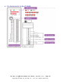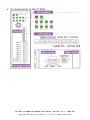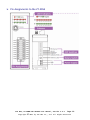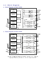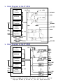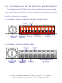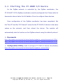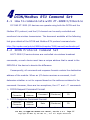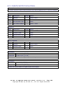
1
ZT-2000 DIO SERIES User Manual Warranty All products manufactured by ICP DAS are under warranty regarding defective materials for a period of one year, beginning from the date of delivery to the original purchaser. Warning ICP DAS assumes no liability for any damage resulting from the use of this product. ICP DAS reserves the right to change this manual at any time without notice. The information furnished by ICP DAS is believed to be accurate and reliable. However, no responsibility is assumed by ICP DAS for its use, nor for any infringements of patents or other rights of third parties resulting from its use. Copyright Copyright © 2013 by ICP DAS. All rights are reserved. Trademarks Names are used for identification purposes only and may be registered trademarks of their respective companies. Technology Support If you have any problems, please feel free to contact us via email at [email protected]. ICP DAS, ZT‐2000 DIO SEIRES User Manual, Version 1.2.1 Page 1 Copyright © 2014 by ICP DAS Co., Ltd. All Rights Reserved. Table of Contents 1 Introduction...................................... 6 1.1 Introduction to ZigBee ................................ 6 1.2 Introduction to the ZT‐2000 DIO Series ............... 7 1.3 Introduction to the ZT‐2042 ........................... 8 1.4 Introduction to the ZT‐2043 ........................... 8 1.5 Introduction to the ZT‐2052 ........................... 9 1.6 Introduction to the ZT‐2053 ........................... 9 1.7 Introduction to the ZT‐2055 .......................... 10 1.8 Introduction to the ZT‐2060 .......................... 10 2 Information to the Hardware...................... 11 2.1 Specifications ........................................ 11 Specifications to ZigBee ................................ 11 Specifications to ZT‐2000 Series Module Board ........... 11 Specifications to the ZT‐2042 ........................... 12 Specifications to the ZT‐2043 ........................... 13 Specifications to the ZT‐2052 ........................... 14 Specifications to the ZT‐2053 ........................... 15 Specifications to the ZT‐2055 ........................... 16 Specifications to the ZT‐2060 ........................... 17 2.2 Pin Assignments ....................................... 18 Pin Assignments to the ZT‐2042 .......................... 18 Pin Assignments to the ZT‐2043 .......................... 19 Pin Assignments to the ZT‐2052 .......................... 20 Pin Assignments to the ZT‐2053 .......................... 21 Pin Assignments to the ZT‐2055 .......................... 22 Pin Assignments to the ZT‐2060 .......................... 23 2.3 Block Diagram ......................................... 24 Block Diagram to the ZT‐2042 ............................ 24 Block Diagram to the ZT‐2043 ............................ 24 Block Diagram to the ZT‐2052 ............................ 25 Block Diagram to the ZT‐2053 ............................ 25 ICP DAS, ZT‐2000 DIO SEIRES User Manual, Version 1.2.1 Page 2 Copyright © 2013 by ICP DAS Co., Ltd. All Rights Reserved. Block Diagram to the ZT‐2055 ............................ 26 Block Diagram to the ZT‐2060 ............................ 26 2.4 Wire Connections ...................................... 27 Wire Connections to the ZT‐2042 ......................... 27 Wire Connections to the ZT‐2043 ......................... 27 Wire Connections to the ZT‐2052 ......................... 28 Wire Connections to the ZT‐2053 ......................... 28 Wire Connections to the ZT‐2055 ......................... 29 Wire Connections to the ZT‐2060 ......................... 30 3 Setting up the ZT‐2000 DIO Device................ 31 3.1 Introduction to the Configuration Parameters ........ 31 3.2 Introduction to the Rotation and DIP Switch ......... 32 3.3 Starting the ZT‐2000 I/O Device ...................... 34 3.4 Examples .............................................. 35 3.5 Communications Testing ............................... 36 4 DCON/Modbus RTU Command Set...................... 37 4.1 How to communicate with ZT‐2000 I/O Device .......... 37 4.2 DCON Protocol Command Set ............................ 37 4.2.1 Checksum ............................................. 38 4.2.2 Overview the DCON Command Sets ..................... 39 4.2.3 %AANNTTCCFF .......................................... 40 4.2.4 #** .................................................. 41 4.2.5 #AA00(Data) .......................................... 42 4.2.6 #AA0A(Data) .......................................... 44 4.2.7 #AA1c(Data) .......................................... 46 4.2.8 #AAAc(Data) .......................................... 48 4.2.9 #AAN ................................................. 49 4.2.10 $AA2 ............................................... 50 4.2.11 $AA4 ............................................... 51 4.2.12 $AA5 ............................................... 53 4.2.13 $AA6 ............................................... 54 4.2.14 $AAC ............................................... 55 4.2.15 $AACN .............................................. 56 4.2.16 $AAF ............................................... 57 4.2.17 $AALS .............................................. 58 4.2.18 $AAM ............................................... 60 ICP DAS, ZT‐2000 DIO SEIRES User Manual, Version 1.2.1 Page 3 Copyright © 2013 by ICP DAS Co., Ltd. All Rights Reserved. 4.2.19 $AAP ............................................... 61 4.2.20 @AA ................................................. 62 4.2.21 @AA(Data) .......................................... 63 4.2.22 ~AAD ............................................... 64 4.2.23 ~AADVV ............................................. 65 4.2.24 ~** ................................................. 66 4.2.25 ~AA0 ............................................... 67 4.2.26 ~AA1 ............................................... 69 4.2.27 ~AA2 ............................................... 70 4.2.28 ~AA3EVV ............................................ 71 4.2.29 ~AA4V .............................................. 72 4.2.30 ~AA5V .............................................. 73 4.3 The Modbus RTU Protocol Command Set ................. 75 4.3.1 Modbus Address Mapping .............................. 76 4.3.2 PLC Address Mapping ................................. 78 4.3.3 01 (0x01) Read the Coils ............................ 79 4.3.4 02 (0x02) Read Discrete Inputs ..................... 82 4.3.5 03 (0x03) Read Multiple Registers .................. 84 4.3.6 04 (0x04) Read Multiple Input Registers ............ 86 4.3.7 05 (0x05) Write a Single Coil ...................... 88 4.3.8 06 (0x06) Write Multiple Registers ................. 91 4.3.9 15(0x0F)Write multiple coils ....................... 93 4.3.10 70 (0x46) Read/Write the Module Settings ......... 95 5 Troubleshooting................................. 108 6 Appendix........................................ 109 6.1 Dual Watchdog Operation ................................ 109 6.2 Reset Status ........................................... 110 6.3 Digital Output ......................................... 111 6.4 Latched Digital Input .................................. 112 6.5 LED Display Status ..................................... 113 ZT‐2042 ................................................ 113 ZT‐2043 ................................................ 114 ZT‐2052 ................................................ 114 ZT‐2053 ................................................ 114 ZT‐2060 ................................................ 115 6.6 The Extension to the Software Address .................. 116 ICP DAS, ZT‐2000 DIO SEIRES User Manual, Version 1.2.1 Page 4 Copyright © 2013 by ICP DAS Co., Ltd. All Rights Reserved. What’s in the Shipping Package? The shipping package contains the following items: ZT‐2000 DIO Module ANT‐124‐05 Quick Start If any of these items are missing or damaged, please contact your local distributor for more information. Save the shipping materials and cartons in case you need to ship the module in the future. More Information Documentation: CD: \Napdos\ZigBee\ZT_Series\Document http://ftp.icpdas.com/pub/cd/usbcd/napdos/zigbee/zt_series/document Software: CD: \Napdos\ZigBee\ZT_Series\Utility http://ftp.icpdas.com/pub/cd/usbcd/napdos/zigbee/zt_series/utility ICP DAS, ZT‐2000 DIO SEIRES User Manual, Version 1.2.1 Page 5 Copyright © 2013 by ICP DAS Co., Ltd. All Rights Reserved. 1 Introduction 1.1 Introduction to ZigBee ZigBee is a specification for a suite of high-level communication protocols using small, low-power digital radios based on the IEEE 802.15.4 standard for personal area networks. ZigBee devices are often used in mesh network form to transmit data over longer distances, passing data through intermediate devices to reach more distant ones. This allows ZigBee networks to be formed ad-hoc, with no centralized control or high-power transmitter/receiver able to reach all of the devices. Any ZigBee device can be tasked with running the network. ZigBee is targeted at applications that require a low data rate, long battery life, and secure networking. ZigBee has a defined rate of 250 kbit/s, best suited for periodic or intermittent data transmission or a single signal transmission from a sensor or input device. Applications include wireless light switches, electrical meters with in-home-displays, traffic management systems, and other consumer and industrial equipment that requires short-range wireless transfer of data at relatively low rates. The technology defined by the ZigBee specification is intended to be simpler and less expensive than other WPANs. ICP DAS, ZT‐2000 DIO SEIRES User Manual, Version 1.2.1 Page 6 Copyright © 2013 by ICP DAS Co., Ltd. All Rights Reserved. 1.2 Introduction to the ZT‐2000 DIO Series ZT-2000 I/O series devices are small wireless ZigBee I/O modules based on the IEEE802.15.4 standard that allow data acqusition and control via personal area ZigBee networks. They provide digital input/output, timer/counter and other functions. These modules can be remotely controlled using a set of DCON or Modbus RTU commands. The DIO modules support TTL signals, photo-isolated digital input, relay contact output, solid-state relay output, PhotoMOS output and open-collector output. See Sec. 2.1 for more detailed information. ZT-2000 I/O series is a wireless data acquisition-based client/server system. Accordingly, a Net Server for the ZigBee (ZT-2570/ZT-2550) is essential in such systems. So, if there is any configuration issue of ZigBee coordinator, please refer to the “ZT-25XX ZigBee Converter Quick Start“ document for more information, which can be found at the following link: http://ftp.icpdas.com/pub/cd/usbcd/napdos/zigbee/zt_series/document/ ICP DAS, ZT‐2000 DIO SEIRES User Manual, Version 1.2.1 Page 7 Copyright © 2013 by ICP DAS Co., Ltd. All Rights Reserved. 1.3 Introduction to the ZT‐2042 The ZT-2042 offers 4 PhotoMOS relay output channels and 4 sink-type digital output channels with short circuit protection. Each channel features photo couple isolation. The ZT-2042 has 8 LED indicators to display the DO channel status. 4kV ESD protection and 3000 V DC intra-module isolation are the standard. Users can easily configure the module address, protocol, checksum, ZB-PID and ZB-channel settings using a combination of rotary and DIP switches. 1.4 Introduction to the ZT‐2043 The ZT-2043 offers 14 sink type digital output channels with short circuit protection. All channels feature photo-couple isolation. The ZT-2043 includes 14 LED indicators to display the DO channel status. 4 kV ESD protection and 3750 V DC intra-module isolation are the standard. Users can easily configure the module address, protocol, checksum, ZB-PID and ZB-channel settings using a combination of rotary and DIP switches. ICP DAS, ZT‐2000 DIO SEIRES User Manual, Version 1.2.1 Page 8 Copyright © 2013 by ICP DAS Co., Ltd. All Rights Reserved. 1.5 Introduction to the ZT‐2052 The ZT-2052 offers 8 digital input channels, each of which features photocouple isolation. In addition, you can choose either sink-type or sourcetype input via wire connections. All channels are able to be used as 16-bit counters. The ZT-2052 has 8 LED indicators to display the channel status and also includes 4 kV ESD protection and 3000 V DC intra-module isolation. Users can easily configure the module address, protocol, checksum, ZB-PID and ZB-channel settings using a combination of rotary and DIP switches. 1.6 Introduction to the ZT‐2053 The ZT-2053 offers 14 digital input channels which can be used for either dry or wet contact. Its effective distance for dry contact is up to 500 meters. All channels are able to be used as 16-bit counters. The ZT-2053 includes 14 LED indicators to display the channel status as well as 4 kV ESD protection and 3750 V rms intra-module isolation. Users can easily to configure the module address, protocol, checksum, ZB-PID and ZB-channel settings using a combination of rotary and DIP switches. ICP DAS, ZT‐2000 DIO SEIRES User Manual, Version 1.2.1 Page 9 Copyright © 2013 by ICP DAS Co., Ltd. All Rights Reserved. 1.7 Introduction to the ZT‐2055 The ZT-2055 offers 8 isolated channels for digital input and 8 isolated channels for digital output. Either sink-type or source-type digital input can be selected via wire connections. All digital input channels are also able to be used as 16-bit counters. The ZT-2055 supports source-type output with short circuit protection. There are options to enable both power-on and safe values. The ZT-2055 has 16 LED indicators to display the channel status, and has 4 kV ESD protection and 2500 V DC intra-module isolation. Users can easily confi gure the module address, protocol, checksum, ZB-PID and ZBchannel settings using a combination of rotary and DIP switches. 1.8 Introduction to the ZT‐2060 The ZT-2060 offers 4 Form A power relay output channels and 6 digital input channels, each of which features photocouple isolation. In addition, you can choose sink-type or source-type input via wire connections. All channels are able to be used as 16-bit counters. The ZT-2060 has 10 LED indicators to display the channel status, and has 4 kV ESD protection and 3000 V DC intramodule isolation. Users can easily configure the module address, protocol, checksum, ZB-PID and ZB-channel settings using a combination of rotary and DIP switches. ICP DAS, ZT‐2000 DIO SEIRES User Manual, Version 1.2.1 Page 10 Copyright © 2013 by ICP DAS Co., Ltd. All Rights Reserved. 2 Information to the Hardware 2.1 Specifications Specifications to ZigBee Wireless RF Channels RF Transmit Power Antenna (2.4 GHz) Transmit Range (LOS) Max. Slaves Supported EMI Certification 16 11 dBm 5 dBi Omni-directional Antenna 700 m (Typical) 255 CE/FCC, FCC ID Specifications to ZT‐2000 Series Module Board Gernal Protocols Hot Swap EMS Protection ESD (IEC 61000-4-2) EFT (IEC 61000-4-4) Surge (IEC 61000-4-5) Mechanical Flammability Dimensions (W x L x H) Installation Environment Operating Temperature Storage Temperature Relative Humidity Supports DCON and Modbus RTU Protocols Rotary and DIP switch ±4 kV Contact for each Terminal ±4 kV for Power Line ±3 kV for Power Line Fire Retardant Materials (UL94-V0 Level) 33 mm x 87 mm x 110 mm DIN-Rail -25 to 75 °C -30 to 80 °C 10 ~ 90% RH, Non-condensing ICP DAS, ZT‐2000 DIO SEIRES User Manual, Version 1.2.1 Page 11 Copyright © 2013 by ICP DAS Co., Ltd. All Rights Reserved. Specifications to the ZT‐2042 Relay Output Output Channels Output Type Load Voltage 4 PhotoMOS Relay, Form A 60 V DC / V AC 60 V/1.0 A Operating Temperature: -25 °C ~ +40 °C 60 V/0.8 A Operating Temperature: +40 °C ~ +60 °C 60 V/0.7 A Operating Temperature: +60 °C ~ +75 °C 5.0 ms 0.5 ms Max. Load Current Power-on Time Power-off Time Digital Output Channels Output Type Max. Load Current Load Voltage External Power Reversed Protection and Short Circuit Protection Current Limited Protection 4 (Sink) Isolated Open Collector 700 mA/channel +5 V DC ~ +50 V DC Yes 1.1 A Gernal LED Indicator PWR ZigBee DO0 ~ DO7 1 Red LED, ZigBee Device Power Indicator 1 Green LED, ZigBee Communication Indicator 8 Red LED, Digital Output Channel Indicators Power Input Voltage Range Power consumption Intra-module Isolated, Field-to-Logic +10 V DC ~ +30 V DC 1.32W (Max.) 3000 V DC ※Please see other specifications to the “Specifications to ZigBee“ and “Specifications to ZT-2000 Series Module Board” topics at the section 2.1. ICP DAS, ZT‐2000 DIO SEIRES User Manual, Version 1.2.1 Page 12 Copyright © 2013 by ICP DAS Co., Ltd. All Rights Reserved. Specifications to the ZT‐2043 Digital Output Channels Output Type Max. Load Current Load Voltage External Power Reversed Protection and Short Circuit Protection Current Limited Protection 14 (Sink) Isolated Open Collector 700 mA/channel +5 V DC ~ +50 V DC Yes 1.1 A Gernal LED Indicator PWR ZigBee DO0 ~ DO13 1 Red LED, ZigBee Device Power Indicator 1 Green LED, ZigBee Communication Indicator 14 Green LED, Digital Output Channel Indicators Power Input Voltage Range Power consumption Intra-module Isolated, Field-to-Logic +10 V DC ~ +30 V DC 0.84W (Max.) 3750 V DC ※Please see other specifications to the “Specifications to ZigBee“ and “Specifications to ZT-2000 Series Module Board” topics at the section 2.1. ICP DAS, ZT‐2000 DIO SEIRES User Manual, Version 1.2.1 Page 13 Copyright © 2013 by ICP DAS Co., Ltd. All Rights Reserved. Specifications to the ZT‐2052 Digital Input Channels Type ON Voltage Level Wet Contact OFF Voltage Level Max. Count Counters Max. Input Frequency Min. Pulse Width Input Impedance 8 Sink/Source +3.5 V DC ~ +30 V DC +1 V DC Max. 16-bit (65535) 100 Hz 5 ms 3 kΩ, 0.33 W Gernal LED Indicator PWR ZigBee DI0 ~ DI7 1 Red LED, ZigBee Device Power Indicator 1 Green LED, ZigBee Communication Indicator 8 Green LED, Digital Input Channel Indicators Power Input Voltage Range Power consumption Intra-module Isolated, Field-to-Logic +10 V DC ~ +30 V DC 1 W (Max.) 3750 V rms ※Please see other specifications to the “Specifications to ZigBee“ and “Specifications to ZT-2000 Series Module Board” topics at the section 2.1. ICP DAS, ZT‐2000 DIO SEIRES User Manual, Version 1.2.1 Page 14 Copyright © 2013 by ICP DAS Co., Ltd. All Rights Reserved. Specifications to the ZT‐2053 Digital Input Channels Type ON Voltage Level OFF Voltage Level Effective Distance for Dry Contact Type ON Voltage Level Dry Contact Wet Contact OFF Voltage Level Max. Count Counters Max. Input Frequency Min. Pulse Width Input Impedance 14 Sink Close to GND Open 500 m Max. Sink/Source +3.5 V DC ~ +30 V DC +1 V DC Max. 16-bit (65535) 100 Hz 5 ms 3 kΩ, 0.33 W Gernal LED Indicator PWR ZigBee DI0 ~ DI13 1 Red LED, ZigBee Device Power Indicator 1 Green LED, ZigBee Communication Indicator 14 Green LED, Digital Input Channel Indicators Power Input Voltage Range Power consumption Intra-module Isolated, Field-to-Logic +10 V DC ~ +30 V DC 0.72 W (Max.) 3750 V DC ※Please see other specifications to the “Specifications to ZigBee“ and “Specifications to ZT-2000 Series Module Board” topics at the section 2.1. ICP DAS, ZT‐2000 DIO SEIRES User Manual, Version 1.2.1 Page 15 Copyright © 2013 by ICP DAS Co., Ltd. All Rights Reserved. Specifications to the ZT‐2055 Digital Input Channels Type ON Voltage Level OFF Voltage Level Effective Distance for Dry Contact Type ON Voltage Level Dry Contact Wet Contact +4 V DC Max. 16-bit (65535) 100 Hz 5 ms 10 kΩ ±70 V DC OFF Voltage Level Max. Count Counters Max. Input Frequency Min. Pulse Width Input Impedance Overvoltage Protection Digital Output Channels Output Type Max. Load Current Load Voltage Overvoltage Protection Overload Protection 8 Source Close to GND Open 500 meters Max. Sink/Source +10 V DC ~ +50 V DC 8 (Sink) Isolated Open Collector 700 mA/channel +3.5 V DC ~ +50 V DC 60 V DC 1.4 A (with short-circuit protection) Gernal LED Indicator PWR ZigBee DO0 ~ DO7 DI0 ~ DI7 1 1 8 8 Red LED, ZigBee Device Power Indicator Green LED, ZigBee Communication Indicator Red LED, Digital Output Channel Indicators Green LED, Digital Input Channel Indicators Power Input Voltage Range Power consumption Intra-module Isolated, Field-to-Logic +10 V DC ~ +30 V DC 2.5 W (Max.) 2500 V DC ※Please see other specifications to the “Specifications to ZigBee” and “Specifications to ZT-2000 Series Module Board” topics at the section 2.1. ICP DAS, ZT‐2000 DIO SEIRES User Manual, Version 1.2.1 Page 16 Copyright © 2013 by ICP DAS Co., Ltd. All Rights Reserved. Specifications to the ZT‐2060 Digital Input Channels 6 Sink/Source +3.5 V DC ~ +30 V DC Type ON Voltage Level Wet Contact OFF Voltage Level Max. Count Counters Max. Input Frequency Min. Pulse Width Input Impedance Relay Output Output Channels Output Type Contact Rating Max. Contact voltage Operate Time Release Time Electrically Endurance Mechanically Between contacts Dielectric Between coil to Strength contacts Insulation Resistance Surge Strength +1 V DC Max. 16-bit (65535) 100 Hz 5 ms 3 kΩ, 0.33 W 4 Power Relay, Form A 5A @ (250 V AC / 30 V DC ) 270 V AC / 125 V DC 10 ms Max. at Rated Voltage 5 ms Max. at Rated Voltage Resistive Load: 100,000ops. Min. (10 ops/minute) At no Load: 20,000,000ops. Min. (300 ops/minute) 750 V AC for 1 Minute 3,000 V AC for 1 minute Min. 1000 MΩ at 500 V DC 5,080V (1.2 / 50us) Gernal LED Indicator PWR ZigBee DI0 ~ DI6 RL0 ~ RL3 1 1 6 4 Red LED, ZigBee Device Power Indicator Green LED, ZigBee Communication Indicator Green LED, Digital Input Channel Indicators Red LED, Digital Output Channel Indicators Power Input Voltage Range Power consumption Intra-module Isolated, Field-to-Logic +10 V DC ~ +30 V DC 1.4 W (Max.) 2500 V DC ※Please see other specifications to the “Specifications to ZigBee“ and “Specifications to ZT-2000 Series Module Board” topics at the section 2.1. ICP DAS, ZT‐2000 DIO SEIRES User Manual, Version 1.2.1 Page 17 Copyright © 2013 by ICP DAS Co., Ltd. All Rights Reserved. 2.2 Pin Assignments Pin Assignments to the ZT‐2042 ICP DAS, ZT‐2000 DIO SEIRES User Manual, Version 1.2.1 Page 18 Copyright © 2013 by ICP DAS Co., Ltd. All Rights Reserved. Pin Assignments to the ZT‐2043 ICP DAS, ZT‐2000 DIO SEIRES User Manual, Version 1.2.1 Page 19 Copyright © 2013 by ICP DAS Co., Ltd. All Rights Reserved. Pin Assignments to the ZT‐2052 ICP DAS, ZT‐2000 DIO SEIRES User Manual, Version 1.2.1 Page 20 Copyright © 2013 by ICP DAS Co., Ltd. All Rights Reserved. Pin Assignments to the ZT‐2053 ICP DAS, ZT‐2000 DIO SEIRES User Manual, Version 1.2.1 Page 21 Copyright © 2013 by ICP DAS Co., Ltd. All Rights Reserved. Pin Assignments to the ZT‐2055 ICP DAS, ZT‐2000 DIO SEIRES User Manual, Version 1.2.1 Page 22 Copyright © 2013 by ICP DAS Co., Ltd. All Rights Reserved. Pin Assignments to the ZT‐2060 Protocol Address MSB ZigBee Pan ID Checksum ZigBee Channel ICP DAS, ZT‐2000 DIO SEIRES User Manual, Version 1.2.1 Page 23 Copyright © 2013 by ICP DAS Co., Ltd. All Rights Reserved. 2.3 Block Diagram Block Diagram to the ZT‐2042 LED Module +5V RL0 COM RL0 NO EEPROM RL3 COM RL3 NO Embedded Controller DI. GND Ext. PWR DO4 ZigBee Module +Vs GND Power Regulator DO7 +5V DO. GND Block Diagram to the ZT‐2043 +5V LED Module DO. PWR DO 0 EEPROM DO 1 … Embedded Controller DO 12 ZigBee Module +Vs GND Power Regulator +5V DO 13 DO. GND ICP DAS, ZT‐2000 DIO SEIRES User Manual, Version 1.2.1 Page 24 Copyright © 2013 by ICP DAS Co., Ltd. All Rights Reserved. Block Diagram to the ZT‐2052 LED Module DI. PWR DI0 EEPROM … Embedded Controller DI6 ZigBee Module +Vs GND Power Regulator +5V DI7 Block Diagram to the ZT‐2053 LED Module Wet. COM IN 0 EEPROM … Embedded Controller IN 12 ZigBee Module +Vs GND Power Regulator IN 13 +5V Dry.GND ICP DAS, ZT‐2000 DIO SEIRES User Manual, Version 1.2.1 Page 25 Copyright © 2013 by ICP DAS Co., Ltd. All Rights Reserved. Block Diagram to the ZT‐2055 LED Module +5V +S5V DI.COM DI0 EEPROM +S5V Embedded Controller DI7 DI.GND +5V ZigBee Module +Vs Power Regulator GND +5V Ext.PWR DO0 +5V +S5V DC/DC GND1 DO7 GND1 DO.GND Block Diagram to the ZT‐2060 +5V LED Module DI0 + DI0 - … EEPROM DI5 + Embedded Controller DI5 RL0 COM ZigBee Module GND Power Regulator +5V … +Vs RL0 NO RL3 COM RL3 NO ICP DAS, ZT‐2000 DIO SEIRES User Manual, Version 1.2.1 Page 26 Copyright © 2013 by ICP DAS Co., Ltd. All Rights Reserved. 2.4 Wire Connections Wire Connections to the ZT‐2042 Wire Connections to the ZT‐2043 ICP DAS, ZT‐2000 DIO SEIRES User Manual, Version 1.2.1 Page 27 Copyright © 2013 by ICP DAS Co., Ltd. All Rights Reserved. Wire Connections to the ZT‐2052 Wire Connections to the ZT‐2053 ICP DAS, ZT‐2000 DIO SEIRES User Manual, Version 1.2.1 Page 28 Copyright © 2013 by ICP DAS Co., Ltd. All Rights Reserved. Wire Connections to the ZT‐2055 ICP DAS, ZT‐2000 DIO SEIRES User Manual, Version 1.2.1 Page 29 Copyright © 2013 by ICP DAS Co., Ltd. All Rights Reserved. Wire Connections to the ZT‐2060 ICP DAS, ZT‐2000 DIO SEIRES User Manual, Version 1.2.1 Page 30 Copyright © 2013 by ICP DAS Co., Ltd. All Rights Reserved. 3 Setting up the ZT‐2000 DIO Device 3.1 Introduction to the Configuration Parameters A. “Pan ID” parameter is the group identity for a ZigBee network, and must the same for all devices in the same ZigBee network. B. “Node ID / Address” parameter is the individed identity of a specific the ZigBee module, and must be unique for each device connected the same ZigBee network. C. “RF Channel” parameter indicates the radio frequency channel, and must be set to the same value as other modules on the same ZigBee network. Channel 0x00 0x01 …… 0x0F Frequency (MHz) 2405 2410 …… 2480 ※ RF channels 0x04, 0x09, 0x0E or 0x0F are recommended because they do not overlap with the Wi-Fi frequencies based. 802.11b/g Channel 1 2400 00 01 02 03 04 MHz 802.11b/g Channel 6 802.11b/g Channel 11 05 06 07 08 09 0A 0B 0C 0D 0E 0F 2485 MHz 802.11b/g Channels (North America) 802.15.4 Channels D. Protocol/Application Mode: When implementing custom programs based on different protocols, the following application modes are recommended in order to ensure communicatible User Program Protocol DCON ZT-2000 I/O ZT-2550 ZT-2570 DCON Transparent Transparent Transparent Transparent Modbus Gateway Modbus Gateway ------ Modbus Gateway Modbus RTU Modbus RTU Modbus TCP Modbus RTU ICP DAS, ZT‐2000 DIO SEIRES User Manual, Version 1.2.1 Page 31 Copyright © 2013 by ICP DAS Co., Ltd. All Rights Reserved. 3.2 Introduction to the Rotation and DIP Switch The configuration of ZT-2000 series can be adjusted by using the external rotary switch and the DIP switches. The ZT-2000 device should only be rebooted once the configuration is complete. DIP Switch to the ZT‐2042/ZT‐2043/ZT‐2053/ZT‐2055 Protocol Pan ID ON 1 Address LSB (Node ID) 2 3 4 5 Address MSB Checksum (Node ID) 6 7 RF Channel 8 9 10 11 12 Reserved DIP Switch to the ZT‐2052/ZT‐2060 Protocol Address LSB (Node ID) Address MSB (Node ID) Pan ID Checksum RF Channel ICP DAS, ZT‐2000 DIO SEIRES User Manual, Version 1.2.1 Page 32 Copyright © 2013 by ICP DAS Co., Ltd. All Rights Reserved. Rotary Switch Address Node ID Address Node ID 0 SW SW 0 10 0x0010 1 01 0x0001 1 11 0x0011 2 02 0x0002 2 12 0x0012 3 03 0x003 3 13 0x013 …… …… …… …… …… …… F 0F 0x000F F 1F 0x001F Note MSB = 0 MSB = 1 ※ Once the address of hardware switch is set to 0x00, it mens the address is using software configurations. Refer Sec. 6.6 for more detailed information. DIP Switch Number Item 1 Address MSB 2 Protocol 3 Checksum 4 ZigBee Pan ID 5 6 7 8 ZigBee RF Channel Status OFF ON OFF ON OFF ON OFF ON OFF ON OFF ON OFF ON OFF ON Comments Valid Address (Node ID) from 0x00 to 0x0F Valid Address (Node ID) from 0x10 to 0x1F DCON Protocol Modbus RTUProtocol Disabled Enabled Pan ID = 0x0000 Pan ID = 0x0001 -----0x08 -----0x04 -----0x02 -----0x01 ICP DAS, ZT‐2000 DIO SEIRES User Manual, Version 1.2.1 Page 33 Copyright © 2013 by ICP DAS Co., Ltd. All Rights Reserved. 3.3 Starting the ZT‐2000 I/O Device As the ZigBee network is controlled by the ZigBee coordinator, the ZT-2550/ZT-2570 (ZigBee coordinator) must be configured first. Please refert to documents shown below for full details of how to configure these devices. Once configuration of the ZigBee coordinator has been completed. Set the ”Pan ID” and the “RF Channel” values for the ZT-2000 I/O device to the same values as the network, and then reboot the device. The module will automatically start to function on the ZigBee network using the default protocol. ※ Documents http://ftp.icpdas.com.tw/pub/cd/usbcd/napdos/zigbee/zt_series/document/zt-255x/ http://ftp.icpdas.com.tw/pub/cd/usbcd/napdos/zigbee/zt_series/document/zt-257x/ ※ Configuration Utility (Used to configure ZT-2000 I/O device Coordinator) http://ftp.icpdas.com.tw/pub/cd/usbcd/napdos/zigbee/zt_series/utility/ ICP DAS, ZT‐2000 DIO SEIRES User Manual, Version 1.2.1 Page 34 Copyright © 2013 by ICP DAS Co., Ltd. All Rights Reserved. 3.4 Examples Configurations of ZT‐2550/ZT‐2570 Configuring the ZT-2000 I/O Device ON 1 1 2 2 3 3 4 5 4 6 7 5 8 9 6 7 10 11 12 8 ON Number Item Status Explain 1 Address MSB OFF Address/Node ID is 01 (Rotation Switch=1) 2 Protocol ON Use Modbus RTU Protocol 3 Checksum OFF Disabled 4 ZigBee Pan ID OFF Pan ID=0x0000 ON 0x08 5 6 ZigBee ON 0x04 7 RF Channel ON 0x02 OFF ------ 8 ZigBee RF Channel = 0x0E ICP DAS, ZT‐2000 DIO SEIRES User Manual, Version 1.2.1 Page 35 Copyright © 2013 by ICP DAS Co., Ltd. All Rights Reserved. 3.5 Communications Testing Once the ZT-2000 I/O device has joined the ZigBee network, the signal quality can be comfirmed by monitoring the status of the ZigBee Net LED indicators. If the LED indicator shows a steady light, communication with the ZT-2000 I/O device has been successfully established for data acquisition and control. ICP DAS also provides the “DCON Utility”, which can be used to simulate DCON/Modbus communication. This software can also be used to verify the device settings and ZigBee I/O functions. ※ The DCON Utility can be dowmload from: http://ftp.icpdas.com/pub/cd/8000cd/napdos/driver/dcon_utility/ Simulating I/O channel operation via the DCON Utility 1. Launch the DCON Utility and select the appropriate COM Port settings to connect to the ZigBee Coordinator (ZT-2550/ZT-2570). 2. Click the “Search” button to start searching for ZT-2000 I/O device connected to the same ZigBee network. 3. If any ZT-2000 I/O devices are found, they will be displayed in the device list window. Double-click the list of the module name to start the platform to operate the I/O channels. 1 2 3 4 ICP DAS, ZT‐2000 DIO SEIRES User Manual, Version 1.2.1 Page 36 Copyright © 2013 by ICP DAS Co., Ltd. All Rights Reserved. 4 DCON/Modbus RTU Command Set 4.1 How to communicate with ZT‐2000 I/O Device ICP DAS ZT-2000 I/O devices can operate using both the DCON and the Modbus RTU protocol, and the I/O channel can be easily controlled and monitored via wireless transmission. The document available at the following link gives details of the DCON and Modbus RTU protocol command sets. http://ftp.icpdas.com/pub/cd/8000cd/napdos/7000/manual/modbusdio.pdf 4.2 DCON Protocol Command Set All ZT-2000 I/O series devices are controlled via wireless broadcast commands, so each device must have a unique address that is saved in the EEPROM of the device to denote the difference. Consequently, all command and response formats contain the destination address of the module. When an I/O device receives a command, it will determine whether or not to respond based on the address contained in the command. However, there are two exceptions, the #** and ~** commands. DCON Request Command Format Delimiter Module Character Address Command [Checksum] CR [Checksum] CR DCON Response Command Format ※ Delimiter Module Character Address Data Note: ʻCRʼ (Carriage Return) is the character used to end a frame. ICP DAS, ZT‐2000 DIO SEIRES User Manual, Version 1.2.1 Page 37 Copyright © 2013 by ICP DAS Co., Ltd. All Rights Reserved. 4.2.1 Checksum Calulate the Checksum: Sum the ASCII code of all the characters contained in the command in addition to the ʻCRʼ terminator. The Checksum is the sum value expressed in Hexadecimal format. Example: Request Command ”$012(CR)” Sum = ʻ$ʼ + ʻ0ʼ + ʻ1ʼ + ʻ2ʼ = 24h + 30h + 31h + 32h = B7h Checksum = “B7” DCON Request Command with Checksum = “$012B7(CR)” Example: Response Command ”!01200600(CR)” Sum = ʻ!ʼ + ʻ0ʼ + ʻ1ʼ + ʻ2ʼ + ʻ0ʼ + ʻ0ʼ + ʻ6ʼ + ʻ0ʼ + ʻ0ʼ = 21h+30h+31h+32h+30h+30h+36h+30h+30h = 1AAh Checksum = “AA” DCON Response Command with Checksum = “!01200600AA(CR)” ※ Note: Checksum is the sum value expressed in capital letters. ICP DAS, ZT‐2000 DIO SEIRES User Manual, Version 1.2.1 Page 38 Copyright © 2013 by ICP DAS Co., Ltd. All Rights Reserved. 4.2.2 Overview the DCON Command Sets General Command Sets Response Description Command Section %AANNTTCCFF !AA Sets the Module Configuration 4.2.3 #** No Response Synchronized Sampling 4.2.4 #AA00(Data) > Sets the Multiple Digital Output (DO0-DO7) 4.2.5 #AA0A(Data) > Sets the Multiple Digital Output (DO0-DO31) 4.2.6 #AA1c(Data) > Sets the Single Digital Output (DO0-DO7) 4.2.7 #AAAc(Data) > Sets the Single Digital Output (DO0-DO31) 4.2.8 #AAN !AA(Data) Reads the Digital Input Counter 4.2.9 $AA2 !AANNTTCCFF Reads the Module Configuration 4.2.10 $AA4 !S(Data) Reads the Synchronized Data 4.2.11 $AA5 !AAS Reads the Reset Status 4.2.12 $AA6 !(Data) Reads the Status of the Digital I/O 4.2.13 $AAC !AA Clears the Latched Digital Input Status 4.2.14 $AACN !AA Clears the Digital InputCounter 4.2.15 $AAF !AA(Data) Reads the firmware Version 4.2.16 $AALS !(Data) Reads the Latched Digital Input Status 4.2.17 $AAM !AA(Data) Reads the Module Name 4.2.18 $AAP !AASC Reads the Communication Protocol 4.2.19 @AA >(Data) Reads the Status of the Digital I/O 4.2.20 @AA(Data) > Sets the Digital Output Channels 4.2.21 ~AAD !AAF Reads the Active Status of the Digital I/O 4.2.22 ~AADVV !AA Sets the Active Status of the Digital I/O 4.2.23 Command Host Watchdog Command Sets Response Description Section ~** No Response Host OK Command 4.2.24 ~AA0 !AASS Reads the Status of the Watchdog 4.2.25 ~AA1 !AA Resets the Timeout Status of the Watchdog 4.2.26 ~AA2 !AAVV Reads the Timeout Value and Watchdog Setting 4.2.27 ~AA3EVV !AA Sets the Timeout Value and Watchdog Setting 4.2.28 ~AA4V !AA(Data) Reads the Power-on/Safe Value 4.2.29 ~AA5V !AA Sets the PowerOn/Safe Value 4.2.30 ~AARDvv !AA Sets the Response Delay Time 4.2.31 ~AARD !AA(Data) Reads the Response Delay Time 4.2.32 ICP DAS, ZT‐2000 DIO SEIRES User Manual, Version 1.2.1 Page 39 Copyright © 2013 by ICP DAS Co., Ltd. All Rights Reserved. 4.2.3 %AANNTTCCFF Description This command is used to set the configuration of a module Syntax %AANNTTCCFF[CHECKSUM](CR) % Delimiter character AA The address of the module to be set in hexadecimal format (00 to FF) NN The new address of the module in hexadecimal format(00 to FF) TT The new type code,DIO devices are always 0x40 CC The new baud rate, ZigBee I/O devices are always 0x0A FF The command is used to update direction of the DI counter. 00: Falling Edge,Checksum Disabled 40: Falling Edge,Checksum Enabled 80: Rising Edge,Checksum Disabled C0: Rising Edge,Checksum Enabled Response Valid Command !AA[CHECKSUM](CR) Invalid Command ?AA[CHECKSUM](CR) ! Delimiter character to indicate that the command was valid ? Delimiter character to indicate that the command was invalid AA The address of the responding module in hexadecimal format (00 to FF) There will be no response if the command syntax is incorrect, there is a communication error, or there is no module with the specified address. Example Command %0101400A80 Response !01 Sets the update directional of the counter for the module 01 to rising edge, and returns a response indicating a valid command. Example Command %0101400A00 Response !01 Sets the update directional of the counter for the module 01 to rising edge, and returns a response indicating a valid command. ※Related Commands: $AA2, ~AAI, ~AATnn ICP DAS, ZT‐2000 DIO SEIRES User Manual, Version 1.2.1 Page 40 Copyright © 2013 by ICP DAS Co., Ltd. All Rights Reserved. 4.2.4 #** Description When this command is received, it will allow all modules to read data and will store the data for later retrieval. Syntax #**[CHECKSUM](CR) # Delimiter character ** The synchronization sampling command Response There is no response to this command. To access the stored sychronzed data, another command, $AA4, must be sent. Example Command #** Response No response Sends the synchronization sampling command. Example Command $014 Response !1FF0000 Sends a command to read the synchronized data. For module 01, the status byte of the response is 1, which means that it is the first time the synchronized data has been read since the previous #** command was recevied (FF is the status of DI channels). Example Command $014 Response !0FF0000 Sends a command to read the synchronized data. For module 01, the status byte of the response is 0, which means that it is NOT the first time the synchronized data has been read since the previous #** command was received (FF is the status of DI channels). ※Related Commands: $AA4 ICP DAS, ZT‐2000 DIO SEIRES User Manual, Version 1.2.1 Page 41 Copyright © 2013 by ICP DAS Co., Ltd. All Rights Reserved. 4.2.5 #AA00(Data) Description This command is used to set the digital output value of the lower eight channels (DO0-DO7) of a specificed module. Syntax #AA00(Data)[CHECKSUM](CR) # Delimiter character AA The address of the module to be set in hexadecimal format (00 to FF) 00 The command to set the digital output value of the lower eight channels (DO0-DO7). (Data) A two-digit hexadecimal value, where bit 0 corresponds to DO0, bit 1 corresponds to DO1, etc. When the bit is ʻ0ʼ, it denotes that the digital output channel is OFF, and ʻ1ʼ denotes that the digital output channel is ON. Response Valid Command >[CHECKSUM](CR) Invalid Command ?AA[CHECKSUM](CR) Ignored Command ! [CHECKSUM](CR) > Delimiter character to indicate that the command was valid ? Delimiter character to indicate that the command was invalid ! Delimiter character to indicate the command was ignored This will be related if a host watchdog timeout has occurred. The digital output channels are set to the safe value, and the digital output value that was sent is ignored. Example Command #020006 Response > Sets the DO0 and DO3 channels of module 02 to OFF and the DO1 and DO2 channels of module 02 to ON, and returns a response indicating that the command was valid. ICP DAS, ZT‐2000 DIO SEIRES User Manual, Version 1.2.1 Page 42 Copyright © 2013 by ICP DAS Co., Ltd. All Rights Reserved. Example Command #020016 Response ?02 Attempts to set the DO1, DO2 and DO5 channels of module 02 to ON, and the DO0, DO3, DO6, DO7 and DO8 channels of module 02 to OFF. A response indicating that the command was invalid is returned because the ZT-2060 only supports DO0 to DO3. Example Command #020005 Response ! Attempts to set the DO0 and DO2 channels of module 02 to ON, and the DO1, DO3, DO5, DO6, DO7 and DO8 channels of module 02 to OFF, but returns a response indicating that a Host watchdog timeout has occurred. The digital output channel is set to the safe value and the command that was sent is ignored. ※Related Commands: #AA0A(Data), #AA1cDD, AAAc(Data), $AA6, @AA, @AA(Data) ICP DAS, ZT‐2000 DIO SEIRES User Manual, Version 1.2.1 Page 43 Copyright © 2013 by ICP DAS Co., Ltd. All Rights Reserved. 4.2.6 #AA0A(Data) Description This command is used to set the value of digital output channels (DO0-DO31) to a specificed module. Syntax #AA0A(Data)[CHECKSUM](CR) # Delimiter character AA The address of the module to be set in hexadecimal format (00 to FF) 00 The command to set the digital output value #AA0A(Data): DO0-DO7 #AA0B(Data): DO8-DO15 #AA0C(Data): DO16-DO23 #AA0D(Data): DO24-DO31 A two-digit hexadecimal value, where bit 0 corresponds to DO0, bit 1 (Data) corresponds to DO1, etc. When the bit is 0, it denotes that the digital output channel is OFF, and 1 denotes that the digital output channel is ON. Response Valid Command >[CHECKSUM](CR) Invalid Command ?AA[CHECKSUM](CR) Ignored Command ! [CHECKSUM](CR) > Delimiter character to indicate that the command was valid ? Delimiter character to indicate that the command was invalid ! Delimiter character to indicate the command was ignored This will be related if a host watchdog timeout has occurred. The digital output channels are set to the safe value, and the digital output value that was sent is ignored. There will be no response if the command syntax is incorrect, there is a communication error, or there is no module with the specified address. Example Command #020A0E Response > Sets the DO0 channel of module 02 to OFF and the DO0, DO1 and DO2 channels of module 02 to ON, and returns a response indicating that the command was valid. ICP DAS, ZT‐2000 DIO SEIRES User Manual, Version 1.2.1 Page 44 Copyright © 2013 by ICP DAS Co., Ltd. All Rights Reserved. Example Command #020A06 Response ! Attempts to set the DO1 and DO2 channels of module 02 to ON, and the DO0 and DO3 channels of module 02 to OFF, but returns a response indicating that a Host watchdog timeout has occurred. The digital output channel is set to the safe value and the command that was sent is ignored. Example Command #020A0F Response > Sets the DO0, DO1, DO2 and DO3 channels of module 02 to ON, and returns a response indicating that the command was valid. Example Command #020A00 Response > Sets the DO0, DO1, DO2 and DO3 channels of module 02 to OFF, and returns a response indicating that the command was valid. ※Related Commands:#AA00(Data), #AA1c(Data), AAAc(Data), $AA6, @AA, @AA(Data) ICP DAS, ZT‐2000 DIO SEIRES User Manual, Version 1.2.1 Page 45 Copyright © 2013 by ICP DAS Co., Ltd. All Rights Reserved. 4.2.7 #AA1c(Data) Description This command is used to set a single digital output channel of the lower eight channels (DO0 ~ DO7) to a specificed module. Syntax #AA1c(Data)[CHECKSUM](CR) # Delimiter character AA The address of the module to be set in hexadecimal format (00 to FF) The command to set a single digital output channel from the lower eight 1 channels. c The command to specify the digital output channel to be set (0 to 7). 00:set the digital output channel to OFF (Data) 01:set the digital output channel to ON Response Valid Command >[CHECKSUM](CR) Invalid Command ?AA[CHECKSUM](CR) Ignored Command ! [CHECKSUM](CR) > Delimiter character to indicate that the command was valid ? Delimiter character to indicate that the command was invalid ! Delimiter character to indicate the command was ignored. This will be related if a host watchdog timeout has occurred. The digital output channels are set to the safe value, and the digital output value that was sent is ignored. Example Command #021001 Response > Sets the DO0 channel of module 02 to ON, and returns a response indicating that the command was valid. Example Command #021401 Response ?02 Attempts to set the DO4 channel of module 02 to ON. A response indicating that the command was invalid is returned because the ZT-2060 only supports DO0 to DO3. ICP DAS, ZT‐2000 DIO SEIRES User Manual, Version 1.2.1 Page 46 Copyright © 2013 by ICP DAS Co., Ltd. All Rights Reserved. ※Related Commands:#AA00(Data)、#AA0A(Data)、AAAc(Data)、$AA6、@AA、 @AA(Data) ICP DAS, ZT‐2000 DIO SEIRES User Manual, Version 1.2.1 Page 47 Copyright © 2013 by ICP DAS Co., Ltd. All Rights Reserved. 4.2.8 #AAAc(Data) Description This command is used to set a single digital output channel (DO0-DO31) of a specificed module Syntax #AAAc(Data)[CHECKSUM](CR) # Delimiter character AA The address of the module to be set in hexadecimal format (00 to FF) A The command to set a single digital output channel. (DO0-DO31) #AAAc(Data): DO0-DO7 #AABc(Data): DO8-DO15 #AACc(Data): DO16-DO23 #AADc(Data): DO24-DO31 c The command to specify the digital output channel to be set (0-7) (Data) 00: Sets the digital output channel to OFF 01: Sets the digital output channel to ON Response Valid Command >[CHECKSUM](CR) Invalid Command ?AA[CHECKSUM](CR) Ignored Command ! [CHECKSUM](CR) > Delimiter character to indicate that the command was valid ? Delimiter character to indicate that the command was invalid ! Delimiter character to indicate the command was ignored. This will be related if a host watchdog timeout has occurred. The digital output channels are set to the safe value, and the digital output value that was sent is ignored. Example Command #02A201 Response > Sets the DO2 channel of module 02 to ON, and returns a response indicating that the command was valid. ※Related Commands:#AA00(Data)、#AA0ADD(Data)、AA1cDD、$AA6、@AA、 @AA(Data) ICP DAS, ZT‐2000 DIO SEIRES User Manual, Version 1.2.1 Page 48 Copyright © 2013 by ICP DAS Co., Ltd. All Rights Reserved. 4.2.9 #AAN Description This command is used to read the digital input counter of channel N of a specified module. Syntax #AAN[CHECKSUM](CR) # Delimiter character AA The address of the module to be read in hexadecimal format (00 to FF) N The channel to be read (DI0 to DIF) Response Valid Command !AA(Data)[CHECKSUM](CR) Invalid Command ?AA[CHECKSUM](CR) ! Delimiter character to indicate that the command was valid ? Delimiter character to indicate that the command was invalid (Data) A five-digital decimal value representing the digital input counter data for the specified channel (00000 to 65535). AA The address of the module responding in hexadecimal format (00 to FF) There will be no response if the command syntax is incorrect, there is a communication error, or there is no module with the specified address. Example Command #011 Response !0100005 Reads data from channel 1 of module 01 and returns a response indicating that the command was valid and that the counter value is 00005. Example Command #015 Response !0100005 Reads data from channel 5 of module 01 and returns a response indicating that the command was valid, and that the counter value is 00005. ※Related Commands: #AACN ICP DAS, ZT‐2000 DIO SEIRES User Manual, Version 1.2.1 Page 49 Copyright © 2013 by ICP DAS Co., Ltd. All Rights Reserved. 4.2.10 $AA2 Description This command is used to read the configuration of the module Syntax $AA2[CHECKSUM](CR) $ Delimiter character AA The address of the module to be read in hexadecimal format (00 to FF) 2 The command to read the configuration of the module Response Valid Command !AATTCCFF[CHECKSUM](CR) Invalid Command ?AA[CHECKSUM](CR) ! Delimiter character to indicate that the command was valid ? Delimiter character to indicate that the command was invalid AA The address of the module responding in hexadecimal format (00 to FF) TT The Type Code of the module and should be 0x40 for DIO module. CC The Baud Rate of the module and should be 0x0A for ZigBee DIO module. FF Checksum and counter update direction settings for the module. 00: Falling Edge,Checksum Disabled 40: Falling Edge,Checksum Enabled 80: Rising Edge,Checksum Disabled C0: Rising Edge,Checksum Enabled There will be no response if the command syntax is incorrect, there is a communication error, or there is no module with the specified address. Example Command $012 Response !01400A80 Reads the configuration of module 01, and returns a reponse indicating that the command was valid, with a value 0x80 indicating the direction of the counter update is rising edge and the checksum disabled. ※Related Commands: %AANNTTCCFF ICP DAS, ZT‐2000 DIO SEIRES User Manual, Version 1.2.1 Page 50 Copyright © 2013 by ICP DAS Co., Ltd. All Rights Reserved. 4.2.11 $AA4 Description This command is used to read the synchronization data that was retrieved from a specificed module the last time the #** command was used. Syntax $AA4[CHECKSUM](CR) $ Delimiter character AA The address of the module to be read in hexadecimal format (00 to FF) 4 The command to read the synchronized data that was retrieved from a specificed module the last time the #** command was used. Response Valid Command !S(Data)[CHECKSUM](CR) Invalid Command ?AA[CHECKSUM](CR) ! Delimiter character to indicate that the command was valid ? Delimiter character to indicate that the command was invalid AA The address of the module responding in hexadecimal format (00 to FF) S The status of the synchronized data 0: This is NOT the first time to read the synchronized data 1:This is the first time to read the synchronized data (Data) Synchronized data. There will be no response if the command syntax is incorrect, there is a communication error, or there is no module with the specified address. Example Command #** Response No response Sends the synchronized sampling command. Command $014 Response !10F0000 Sends a command to read the synchronized data from module 01. The module returns a reponse indicating that the command was valid, containing the synchronized data and sets the status byte to 1 to indicate that this is the first time the synchronized data has been read. (Digital Input : 0F) ICP DAS, ZT‐2000 DIO SEIRES User Manual, Version 1.2.1 Page 51 Copyright © 2013 by ICP DAS Co., Ltd. All Rights Reserved. Command $024 Response !00053F00 Sends a command to read the synchronized data from module 01. The module returns a reponse indicating that the command was valid, containing the synchronized data and sets the status byte to 0 to indicate that the synchronized data has been read previously. (Digital Output: 05; Digital Input: 3F) ※Related Commands:#** ICP DAS, ZT‐2000 DIO SEIRES User Manual, Version 1.2.1 Page 52 Copyright © 2013 by ICP DAS Co., Ltd. All Rights Reserved. 4.2.12 $AA5 Description This command is used to read the reset status of a specified module. Syntax $AA5[CHECKSUM](CR) $ Delimiter character AA The address of the module to be read in hexadecimal format (00 to FF) 5 The command to read the reset status of the module Response Valid Command !AAS(Data)[CHECKSUM](CR) Invalid Command ?AA[CHECKSUM](CR) ! Delimiter character to indicate that the command was valid ? Delimiter character to indicate that the command was invalid AA The address of the responding module in hexadecimal format (00 to FF) S The reset status of the module 1: This is the first time the command has been sent since the module was powered on. 0: This is NOT the first time the command has been sent since the module was powered on, which denotes that there has been no module reset since the last $AA5 command was sent. There will be no response if the command syntax is incorrect, there is a communication error, or there is no module with the specified address. Example Command $015 Response !011 Reads the reset status of module 01. The module returns a response showing that the command was valid and it is the first time the $AA5 command has been sent since the module was powered-on. Example Command $015 Response !010 Reads the reset status of module 01. The module returns a response showing that the command was valid and it is NOT the first time the $AA5 command has been sent since the module was powered-on. ICP DAS, ZT‐2000 DIO SEIRES User Manual, Version 1.2.1 Page 53 Copyright © 2013 by ICP DAS Co., Ltd. All Rights Reserved. 4.2.13 $AA6 Description This command is used to read the status of the digital input/output channels of a specified module Syntax $AA6[CHECKSUM](CR) $ Delimiter character AA The address of the module to be read in hexadecimal format (00 to FF) 6 The command to read the status of the digital input/output channels. Response Valid Command !(Data)[CHECKSUM](CR) Invalid Command ?AA[CHECKSUM](CR) ! Delimiter character to indicate that the command was valid ? Delimiter character to indicate that the command was invalid (Data) A six-digit hexadecimal value indicating the status of the digital input/output channels. There will be no response if the command syntax is incorrect, there is a communication error, or there is no module with the specified address. Example Command $016 Response !FF0000 Reads the status of the digital input/output channel of module 01 and returns a reponse indicating that the command was valid. (Digital Input: FF) Example Command $026 Response !070F00 Read the status of the digital input/output channel of module 02 and returns a reponse indicating that the command was valid. (Digital Output: 07; Digital Input: 0F) ※Related Commands: #AA00(Data), #AA0A(Data), AA1c(Data), #AAAc(Data), @AA, @AA(Data) ICP DAS, ZT‐2000 DIO SEIRES User Manual, Version 1.2.1 Page 54 Copyright © 2013 by ICP DAS Co., Ltd. All Rights Reserved. 4.2.14 $AAC Description This command is used to clear the status of the latched digital input channels of a specificed module. Syntax $AAC[CHECKSUM](CR) $ Delimiter character AA The address of the module to be cleared in hexadecimal format (00 to FF) C Clear the status of the latched digital input channels Response Valid Command !AA[CHECKSUM](CR) Invalid Command ?AA[CHECKSUM](CR) ! Delimiter character to indicate that the command was valid ? Delimiter character to indicate that the command was invalid AA The address of the responding module in hexadecimal format (00 to FF) There will be no response if the command syntax is incorrect, there is a communication error, or there is no module with the specified address. Example Command @016 Response > Sets the DO1 and DO2 channel of module 01 to ON, and the DO0, DO3 channel to OFF, and returns a response indicating that the command was valid. Command $01C Response !01 Clears the status of the latched digital input channels of module 01, and returns a response indicating that the command was valid. Command $01L0 Response !093F00 Sends the command to read the status of the low latched digital input channels of module 01, and returns a response indicating that the command was valid. (Low Latched DI: 3F; Low Latched DO: 09) ※Related Commands:$AALS ICP DAS, ZT‐2000 DIO SEIRES User Manual, Version 1.2.1 Page 55 Copyright © 2013 by ICP DAS Co., Ltd. All Rights Reserved. 4.2.15 $AACN Description This command is used to clear the digital input counter for channel N of a specificed module. Syntax $AACN[CHECKSUM](CR) $ Delimiter character AA The address of the module to be cleared in hexadecimal format (00 to FF) C The command to clear the digital input counter of channel N N The command to clear the digital input counter of channel N Response Valid Command !AA[CHECKSUM](CR) Invalid Command ?AA[CHECKSUM](CR) ! Delimiter character to indicate that the command was valid ? Delimiter character to indicate that the command was invalid AA The address of the responsding module in hexadecimal format (00 to FF) There will be no response if the command syntax is incorrect, there is a communication error, or there is no module with the specified address. Example Command #011 Response !0100009 Reads the counter data from channel 1 of module 01 and returns a response indicating that the command was valid and that the counter value is 00009. Command $01C1 Response !01 Clears the counter value for channel 1 of module 01, and returns a response indicating that the command was valid. Command #011 Response !0100000 Reads the counter value for channel 1 of module 01 and returns a response indicating that the command was valid and that the counter value is 00000. ※Related Commands:#AAN ICP DAS, ZT‐2000 DIO SEIRES User Manual, Version 1.2.1 Page 56 Copyright © 2013 by ICP DAS Co., Ltd. All Rights Reserved. 4.2.16 $AAF Description This command is used to read the firmware version of a specificed module. Syntax $AAF[CHECKSUM](CR) $ Delimiter character AA The address of the module to be read in hexadecimal format (00 to FF) F The command to read the firmware version of the module. Response Valid Command !AA(Data)[CHECKSUM](CR) Invalid Command ?AA[CHECKSUM](CR) ! Delimiter character to indicate that the command was valid ? Delimiter character to indicate that the command was invalid AA The address of the responding module in hexadecimal format (00 to FF) (Data) The firmware version of the module as a string value There will be no response if the command syntax is incorrect, there is a communication error, or there is no module with the specified address. Example Command $01F Response !0102.00 Reads the firmware version of module 01, and returns a response indicating that the command was valid and showing that the firmware version is 02.00. ICP DAS, ZT‐2000 DIO SEIRES User Manual, Version 1.2.1 Page 57 Copyright © 2013 by ICP DAS Co., Ltd. All Rights Reserved. 4.2.17 $AALS Description This command is used to read the status of the latched digital input channels. Syntax $AALS[CHECKSUM](CR) $ Delimiter character AA The address of the module to be read in hexadecimal format (00 to FF) L Read the status of the latched digital input channels. S The command to read the status of the latched digital input channels 0: Low latched channels 1: High lathched channels Response Valid Command !(Data)[CHECKSUM](CR) Invalid Command ?AA[CHECKSUM](CR) ! Delimiter character to indicate that the command was valid ? Delimiter character to indicate that the command was invalid AA The address of the responding module in hexadecimal format (00 to FF) (Data) The status of the latched digital input channels. A four-digit hexadecimal value followed by 00. There will be no response if the command syntax is incorrect, there is a communication error, or there is no module with the specified address. Example Command @016 Response > Sets the DO1 and DO2 channel of module 01 to ON, and the DO0, DO3 channel to OFF, and returns a response indicating that the command was valid. Command $01C Response !01 Clears the status of the latched digital input channels of module 01, and returns a response indicating that the command was valid. ICP DAS, ZT‐2000 DIO SEIRES User Manual, Version 1.2.1 Page 58 Copyright © 2013 by ICP DAS Co., Ltd. All Rights Reserved. Command $01L0 Response !093F00 Sends the command to read the status of the low latched digital input channels of module 01, and returns a response indicating that the command was valid. (Low Latched DI: 3F; Low Latched DO: 09) Command $01L1 Response !060000 Sends the command to read the status of the high latched digital input channels of module 01, and returns a response indicating that the command was valid. (High Latched DI : 00; High Latched DO : 06 ) ※Related Commands:$AAC ICP DAS, ZT‐2000 DIO SEIRES User Manual, Version 1.2.1 Page 59 Copyright © 2013 by ICP DAS Co., Ltd. All Rights Reserved. 4.2.18 $AAM Description This command is used to read the name of a module. Syntax $AAM[CHECKSUM](CR) $ Delimiter character AA The address of the module to be read in hexadecimal format (00 to FF) M The command to read the name of the module. Response Valid Command !AA(Data)[CHECKSUM](CR) Invalid Command ?AA[CHECKSUM](CR) ! Delimiter character to indicate that the command was valid ? Delimiter character to indicate that the command was invalid AA The address of the responding module in hexadecimal format (00 to FF) (Data) The name of the module as a string value. There will be no response if the command syntax is incorrect, there is a communication error, or there is no module with the specified address. Example Command $01M Response !01ZT-2060 Reads the name of module 01, and returns a response indicating that the command was valid, and that the name of the module is “ZT-2060”. ICP DAS, ZT‐2000 DIO SEIRES User Manual, Version 1.2.1 Page 60 Copyright © 2013 by ICP DAS Co., Ltd. All Rights Reserved. 4.2.19 $AAP Description This command is used to read the communication protocol information for a specificed module. Syntax $AAP[CHECKSUM](CR) $ Delimiter character AA The address of the module to be read in hexadecimal format (00 to FF) P The command to read the communication protocol information Response Valid Command !AASC[CHECKSUM](CR) Invalid Command ?AA[CHECKSUM](CR) ! Delimiter character to indicate that the command was valid ? Delimiter character to indicate that the command was invalid AA The address of the responding module in hexadecimal format (00 to FF) S The protocol(s) supported by the module 0:DCON 1:DCON and Modbus RTU 3:DCON and Modbus RTU/ASCII C The protocol is current used 0:DCON 1:Modbus RTU 3:Modbus ASCII There will be no response if the command syntax is incorrect, there is a communication error, or there is no module with the specified address. Example Command $01P Response !0110 Reads the communication protocol information for module 01 and returns a response indicating that the command was valid with a value of 10, meaning that the module supports the DCON and Modbus RTU protocols and that the protocol which will be used at the next power-on reset is DCON. ICP DAS, ZT‐2000 DIO SEIRES User Manual, Version 1.2.1 Page 61 Copyright © 2013 by ICP DAS Co., Ltd. All Rights Reserved. 4.2.20 @AA Description This command is used to read the status of the digital input/output ports of a specificed module. Syntax @AA[CHECKSUM](CR) @ Delimiter character AA The address of the module to be read in hexadecimal format (00 to FF) Response Valid Command >(Data)[CHECKSUM](CR) Invalid Command ?AA[CHECKSUM](CR) > Delimiter character to indicate that the command was valid ? Delimiter character to indicate that the command was invalid AA The address of the responding module in hexadecimal format (00 to FF) (Data) A four-digital hexadecimal value representing the status of the digital input/output ports. There will be no response if the command syntax is incorrect, there is a communication error, or there is no module with the specified address. Example Command @02 Response >0F0F Reads the status of the digital input/output port of module 02, a response indicating that the command was valid, with a value of 0F0F, which denotes that channels RL0, RL1, RL2 and RL3 are ON and channels IN0, IN1, IN2 and IN3 are also ON. ※Related Commands:#AA00(Data)、#AA0A(Data)、#AA1c(Data)、#AAAc(Data)、$AA6 @AA(Data) ICP DAS, ZT‐2000 DIO SEIRES User Manual, Version 1.2.1 Page 62 Copyright © 2013 by ICP DAS Co., Ltd. All Rights Reserved. 4.2.21 @AA(Data) Description This command is used to enable the digital output channels of a specificed module. Syntax @AA(Data)[CHECKSUM](CR) @ Delimiter character AA The address of the module to be enabled in hexadecimal format (00 to FF) (Data) The data to be written to the digital output channels: Bit 0 of the value corresponds to DO0, and bit 1 corresponds to DO1, etc. When the bit is 1, it denotes that the digital output channel is ON, and 0 denotes that the digital output channel is OFF. Response Valid Command >[CHECKSUM](CR) Invalid Command ?AA[CHECKSUM](CR) Ignored Command ! [CHECKSUM](CR) > Delimiter character to indicate that the command was valid ? Delimiter character to indicate that the command was invalid ! Delimiter character to indicate the command was ignored. This will be returned if a Host Watchdog timeout has occurred. The digital output channels are set to the safe value, and the digital output value that was sent is ignored. There will be no response if the command syntax is incorrect, there is a communication error, or there is no module with the specified address. Example Command @02F Response > Sets the DO0, DO1, DO2 and DO3 channel of module 01 to ON, and returns a response indicating that the command was valid. ※Related Commands:#AA00(Data)、#AA0A(Data)、#AA1c(Data)、#AAAc(Data)、$AA6 @AA ICP DAS, ZT‐2000 DIO SEIRES User Manual, Version 1.2.1 Page 63 Copyright © 2013 by ICP DAS Co., Ltd. All Rights Reserved. 4.2.22 ~AAD Description This command is used to read the Active Status of the Digital I/O of a specificed module. Syntax ~AAD[CHECKSUM](CR) ~ Delimiter character AA The address of the module to be read in hexadecimal format (00 to FF) D The command to read the active status of digital I/O Response Valid Command !AAVV[CHECKSUM](CR) Invalid Command ?AA[CHECKSUM](CR) ! Delimiter character to indicate that the command was valid ? Delimiter character to indicate that the command was invalid AA The address of the responding module in hexadecimal format (00 to FF) VV A two-digit hexadecimal value indicating the active status of the digital I/O. There will be no response if the command syntax is incorrect, there is a communication error, or there is no module with the specified address. Bit 7 6 5 4 3 2 Reserved 1 0 OAS IAS Active Status – DO 0: An output value of 0 indicates that the relay is inactive OAS An output value of 1 indicates that the relay is active 1: An output value of 0 indicates that the relay is active An output value of 1 indicates that the relay is inactive Active Status – DI 0: Input value 1 for no-signal or low voltage IAS Input value 0 for high voltage 1: Input value 0 for no-signal or low voltage Input value 1 for high voltage ※Related Commands: ~AADVV ICP DAS, ZT‐2000 DIO SEIRES User Manual, Version 1.2.1 Page 64 Copyright © 2013 by ICP DAS Co., Ltd. All Rights Reserved. 4.2.23 ~AADVV Description This command is used to set the Active Status of Digital I/O of a specificed module Syntax ~AADVV[CHECKSUM](CR) ~ Delimiter character AA The address of the module to be set in hexadecimal format (00 to FF) D The command to set the active status of the digital I/O. VV A two-digit hexadecimal value indicating the active status of the digital I/O. Response Valid Command !AA[CHECKSUM](CR) Invalid Command ?AA[CHECKSUM](CR) ! Delimiter character to indicate that the command was valid ? Delimiter character to indicate that the command was invalid AA The address of the responding module in hexadecimal format (00 to FF) There will be no response if the command syntax is incorrect, there is a communication error, or there is no module with the specified address. Example Command ~02D03 Response !02 Sets the active status of digital I/O of module 02 and returns a response indicating that the command was valid.. Command ~02D Response !0203 Reads the active status of digital I/O of module 02 and returns a response indicating that the command was valid with the value to the active status is 03. ※Related Commands:~AAD ICP DAS, ZT‐2000 DIO SEIRES User Manual, Version 1.2.1 Page 65 Copyright © 2013 by ICP DAS Co., Ltd. All Rights Reserved. 4.2.24 ~** Description This command is used to inform all modules that the host is OK. Syntax ~**[CHECKSUM](CR) ~ Delimiter character ** The “Host OK” command Response There is no response to this command ※Related Commands:~AA0, ~AA1, ~AA2, ~AA3EVV, ~AA4V, ~AA5V ICP DAS, ZT‐2000 DIO SEIRES User Manual, Version 1.2.1 Page 66 Copyright © 2013 by ICP DAS Co., Ltd. All Rights Reserved. 4.2.25 ~AA0 Description This command is used to read the status of the Host Watchdog for a specoficed module. Syntax ~AA0[CHECKSUM](CR) ~ Delimiter character AA The address of the module to be read in hexadecimal format (00 to FF) 0 The command to read the status of the Host Watchdog Response Valid Command !AASS[CHECKSUM](CR) Invalid Command ?AA[CHECKSUM](CR) ! Delimiter character to indicate that the command was valid ? Delimiter character to indicate that the command was invalid AA The address of the responding module in hexadecimal format (00 to FF) SS Two hexadecimal digits that represent the status of the Host Watchdog, where: Bit 7: 0 indicates that the Host Watchdog is disabled, and 1 indicates that the Host Watchdog is enabled Bit 2: 0 indicates that no Host Watchdog timeout has occurred, and 1 indicates that a Host Watchdog timeout has occurred The host watchdog status is stored in EEPROM and can only be reset by using the ~AA1 command. There will be no response if the command syntax is incorrect, there is a communication error, or there is no module with the specified address. Example Command ~030 Response !0304 Reads the status of the Host Watchdog for module 03 and returns a response indicating that the command was valid and the that the Host Watchdog timeout has occurred. ICP DAS, ZT‐2000 DIO SEIRES User Manual, Version 1.2.1 Page 67 Copyright © 2013 by ICP DAS Co., Ltd. All Rights Reserved. Example Command ~030 Response !0300 Reads the status of the Host Watchdog for module 03 and returns a response indicating that the command was valid, with a value of 00, meaning that the Host Watchdog is disabled and no Host Watchdog timeout has occurred. Example Command ~030 Response !0380 Reads the status of the Host Watchdog for module 03 and returns a response indicating that the command was valid, with a value of 08, meaning that the Host Watchdog is enabled. Send the ~AA1 command to reset the status of the Host Watchdog. ※Related Commands: ~**, ~AA1, ~AA2, ~AA3EVV, ~AA4V, ~AA5V ICP DAS, ZT‐2000 DIO SEIRES User Manual, Version 1.2.1 Page 68 Copyright © 2013 by ICP DAS Co., Ltd. All Rights Reserved. 4.2.26 ~AA1 Description This command is used to reset the status of the Host Watchdog timeout for a specificed module Syntax ~AA1[CHECKSUM](CR) ~ Delimiter character AA The address of the module to be reset in hexadecimal format (00 to FF) 1 The command to reset the status of the Host Watchdog timeout Response Valid Command !AA[CHECKSUM](CR) Invalid Command ?AA[CHECKSUM](CR) ! Delimiter character to indicate that the command was valid ? Delimiter character to indicate that the command was invalid AA The address of the responding module in hexadecimal format (00 to FF) There will be no response if the command syntax is incorrect, there is a communication error, or there is no module with the specified address Example Command ~030 Response !0304 Reads the status of the Host Watchdog for module 03 and returns a response indicating that the command was valid and the that the Host Watchdog timeout has occurred. Command ~031 Response !03 Resets the status of the Host Watchdog timeout for module 03 and returns a response indicating that the command was valid. ※Related Commands: ~**, ~AA0, ~AA2, ~AA3EVV, ~AA4V, ~AA5V ICP DAS, ZT‐2000 DIO SEIRES User Manual, Version 1.2.1 Page 69 Copyright © 2013 by ICP DAS Co., Ltd. All Rights Reserved. 4.2.27 ~AA2 Description This command is used to read the Host Watchdog timeout value for a specificed module Syntax ~AA2[CHECKSUM](CR) ~ Delimiter character AA The address of the module to be read in hexadecimal format (00 to FF) 2 The command to read the Host Watchdog timeout value Response Valid Command !AAEVV[CHECKSUM](CR) Invalid Command ?AA[CHECKSUM](CR) ! Delimiter character to indicate that the command was valid ? Delimiter character to indicate that the command was invalid AA The address of the responding module in hexadecimal format (00 to FF) E 0: The status of the Host Watchdog is disabled 1: The status of the Host Watchdog is enabled VV Two hexadecimal digits to represent the timeout value in tenths of a second. Eg, 01 denotes 0.1 seconds and FF denotes 25.5 seconds. There will be no response if the command syntax is incorrect, there is a communication error, or there is no module with the specified address. Example Command ~032 Response !03190 Reads the status of the Host Watchdog timeout value for module 03 and returns a response indicating that the command was valid, with a value of 0x90, which denotes that the Host Watchdog is enabled and that the Host Watchdog timeout value is 14.4 seconds. ※Related Commands: ~**, ~AA0, ~AA1, ~AA3EVV, ~AA4V, ~AA5V ICP DAS, ZT‐2000 DIO SEIRES User Manual, Version 1.2.1 Page 70 Copyright © 2013 by ICP DAS Co., Ltd. All Rights Reserved. 4.2.28 ~AA3EVV Description This command is used to enable/disable the Host Watchdog for a specidiced module and sets the Host Watchdog timeout value. Syntax ~AA3EVV[CHECKSUM](CR) ~ Delimiter character AA The address of the module to be configured in hexadecimal format (00 to FF) 3 The command to enable or disable the Host Watchdog E 0: Disables the Host Watchdog 1: Enables the Host Watchdog VV Two hexadecimal digits to represent the Host Watchdog timeout value in tenths of a second. Eg: 01 denotes 0.1 seconds and FF denotes 25.5 seconds Response Valid Command !AA[CHECKSUM](CR) Invalid Command ?AA[CHECKSUM](CR) ! Delimiter character to indicate that the command was valid ? Delimiter character to indicate that the command was invalid AA The address of the responding module in hexadecimal format (00 to FF) There will be no response if the command syntax is incorrect, there is a communication error, or there is no module with the specified address Example Command ~013164 Response !01 Enables the Host Watchdog for module 01 and sets the Host Watchdog timeout value to 10.0 seconds. The module returns a response indicating that the command was valid. Command ~012 Response !01164 Reads the Host Watchdog timeout value for module 01. The module returns a response indicating that the command was valid, with a value of 164, which denotes that the Host Watchdog is enabled and the that the Host Watchdog timeout value is 10.0 seconds. ※Related Commands: ~**, ~AA0, ~AA1, ~AA2, ~AA4V, ~AA5V ICP DAS, ZT‐2000 DIO SEIRES User Manual, Version 1.2.1 Page 71 Copyright © 2013 by ICP DAS Co., Ltd. All Rights Reserved. 4.2.29 ~AA4V Description This command is used to read the power-on DO value or the safe DO value for a specificed module Syntax ~AA4V[CHECKSUM](CR) ~ Delimiter character AA The address of the module to be read in hexadecimal format (00 to FF) 4 The command to read the power-on DO value or the safe DO value V P: Power-on Value S: Safe Value Response Valid Command !AA(Data)[CHECKSUM](CR) Invalid Command ?AA[CHECKSUM](CR) ! Delimiter character to indicate that the command was valid ? Delimiter character to indicate that the command was invalid AA The address of the responding module in hexadecimal format (00 to FF) (Data) Power-on or Safe Value There will be no response if the command syntax is incorrect, there is a communication error, or there is no module with the specified address. Example Command ~034P Response !030700 Reads the power-on DO value for module 03 and returns a response indicating that the command was valid, with a value of 0700, which denotes that the DO0, DO1 and DO2 channels of module 03 will be enabled if rebooting. Example Command ~034S Response !030F00 Reads the safe DO value for module 03 and returns a response indicating that the command was valid, with a value of 0F00, with a value of 0F00, which denotes that the DO0, DO1, DO2 and DO3 channels of module 03 will be enabled if watchdog enabled. ※Related Commands: ~AA5V ICP DAS, ZT‐2000 DIO SEIRES User Manual, Version 1.2.1 Page 72 Copyright © 2013 by ICP DAS Co., Ltd. All Rights Reserved. 4.2.30 ~AA5V Description This command is used to set the current DO value for a specificed module as either the power-on DO value or the safe DO value. Syntax ~AA5V[CHECKSUM](CR) ~ Delimiter character AA The address of the module to be set in hexadecimal format (00 to FF) 5 The command to set the power-on DO value or the safe DO value V P: Power-on Value S: Safe Value Response Valid Command !AA[CHECKSUM](CR) Invalid Command ?AA[CHECKSUM](CR) ! Delimiter character to indicate that the command was valid ? Delimiter character to indicate that the command was invalid AA The address of the responding module in hexadecimal format (00 to FF) There will be no response if the command syntax is incorrect, there is a communication error, or there is no module with the specified address Example Command @037 Response > Sets the DO0, DO1 and DO2 channels of module 01 to ON, and the DO3 channel to OFF, and returns a response indicating that the command was valid. Command ~035P Response !03 Sets the power-on DO value for module 03 and the module returns a response indicating that the command was valid. ICP DAS, ZT‐2000 DIO SEIRES User Manual, Version 1.2.1 Page 73 Copyright © 2013 by ICP DAS Co., Ltd. All Rights Reserved. Example Command @03F Response > Sets the DO0, DO1, DO2 and DO3 channels of module 01 to ON, and returns a response indicating that the command was valid. Command ~035S Response !03 Sets the safe DO value for module 03 and the module returns a response indicating that the command was valid. ※Related Commands: ~AA4V ICP DAS, ZT‐2000 DIO SEIRES User Manual, Version 1.2.1 Page 74 Copyright © 2013 by ICP DAS Co., Ltd. All Rights Reserved. 4.3 The Modbus RTU Protocol Command Set The Modbus Protocol was developed by Modicon Inc., and was originally designed for Modicon controllers. Detailed information regarding the Modbus RTU Protocol can be found at: http://www.modicon.com and http://www.modbus.org Modbus RTU Command Format Field Field Field Field Field 1 2 3 4~n n+1~n+2 Function Code Sub Function Module Address Configuration Field CRC16 Function Code Description 0x01 Reads the coils 0x02 Reads the discrete inputs 0x03 Reads multiple registers 0x04 Reads multiple input registers 0x05 Writes to a single coil 0x0F Writes to multiple coils Examples: A. To modify the power-on value for module 01, the following command should be sent 01 46 27 0F BB F9 B. To read the current DI value of channels 0 to 5, the following command should be sent: 01 02 00 00 00 05 B8 09 C. To write the DO value 0x0F from channels 0 to 4, the following command should be sent: 01 0F 00 00 00 04 01 FF 7E D6 D. To only set the DO value of channel 2 to 1, the following command should be sent: 01 05 00 02 FF 00 2D FA ICP DAS, ZT‐2000 DIO SEIRES User Manual, Version 1.2.1 Page 75 Copyright © 2013 by ICP DAS Co., Ltd. All Rights Reserved. 4.3.1 Modbus Address Mapping Address Mapping Address Description Attribute 00001 The Digital Output Channel R/W 00033 The Digital Input Channel R 10001 The Digital Input Channel R 00065 The High Latched DI/O Channels R 00097 The Low Latched DI/O Channels R 00129 The Safe Value R/W 00161 The Power-on Value R/W 40485 The Module Address. Valid Range is 1~247 R/W (1) Bits 5:0 (Baud Rate) Valid Range: 0x03-0x0A 40486 (2) Bits 7:6 (Data Format) 00: No Parity, 1 Stop Bit R/W 10: Even Parity, 1 Stop Bit 11: Odd Parity, 1 Stop Bit 00264 Used to Clear the Latched DI/O W 00513 Used to Clear the DI Count W 40481 The Firmware Version (Low Word) R 40482 The Firmware Version (High Word) R 40483 The Module Name (Low Word) R 40484 The Module Name (High Word) R 30001 The DI Count Value R The Modbus Host Watchdog Mode: 00260 0: The same as I-7000 series modules 1: The AO and DO commands can be used to clear R/W the status of Host Watchdog timeout 00261 00270 40492 40489 Enables or disables the Host Watchdog. Write 0 to disable and 1 to enable. The Host Watchdog Timeout Status. (Write 1 to clear the Host Watchdog timeout status) The Host Watchdog Timeout Count (Write 0 to clear the Host Watchdog timeout count) The Host Watchdog Timeout Value. R/W R/W R/W R/W ICP DAS, ZT‐2000 DIO SEIRES User Manual, Version 1.2.1 Page 76 Copyright © 2013 by ICP DAS Co., Ltd. All Rights Reserved. Valid Range is 0~255 in 0.1/s intervals 00257 The Current Protocol, 0: DCON, 1: Modbus R/W The Reset Status 1: This is the first time the module has been read 10273 after being powered on R 0: This is NOT the first time the module has been read after being powered on 312345 412345 Informs all modules that the Host is OK R ICP DAS, ZT‐2000 DIO SEIRES User Manual, Version 1.2.1 Page 77 Copyright © 2013 by ICP DAS Co., Ltd. All Rights Reserved. 4.3.2 PLC Address Mapping Function Code Description Section 0x01 Reads the Coils 4.3.3 0x02 Reads the Discrete Inputs 4.3.4 0x03 Reads Multiple Registers 4.3.5 0x04 Reads Multiple Input Registers 4.3.6 0x05 Writes a Single Coil 4.3.7 0x06 Writes Multiple Registers 4.3.8 0x0F Writes Multiple Coils 4.3.9 0x46 Reads/Writes the Module Settings 4.3.10 If the function specified in the message is not supported, then the module will respond as below. Note that the Address mapping of the Protocol is base 0. Error Response Number Description Length Value 00 Address 1 0x01 to 0xF7 01 Function Code 1 Function Code + 0x80 02 Exception Code 1 01 Note: If a CRC mismatch occurs, the module will not respond. ICP DAS, ZT‐2000 DIO SEIRES User Manual, Version 1.2.1 Page 78 Copyright © 2013 by ICP DAS Co., Ltd. All Rights Reserved. 4.3.3 01 (0x01) Read the Coils Description This function code is used to read the current digital output readback value of the ZT-2000 I/O module. Request Byte Description Length Value 00 Address 1 0x01 to 0xF7 01 Function Code 1 0x01 Starting Channel 02-03 Numbers or Address 2 Mapping DO 0x0000 ~ 0x001F DI 0x0020 ~ 0x003F DI/O Latch High 0x0040 ~ 0x005F DI/O Latch Low 0x0060 ~ 0x007F Safe Value 0x0080 ~ 0x009F Power-on Value 0x00A0 ~ 0x00BF Reads the WDT Mode 0x0103 Reads the WDT Enable 0x0104 Read WDT Status 0x010D Read Protocol 0x0100 Read Reset Status 0x0110 Output Channel 04-05 Number or 2 0x0001-0x0020 (Bit Count) Bit Count Response Byte Description Length Value 00 Address 1 0x01 to 0xF7 01 Function Code 1 0x01 02 Byte Count 1 03 Bit Values B Byte Count of the Response [B = (Bit Count + 7)/8] (Bit Values) Error Response Byte Description Length Value 00 Address 1 0x01 to 0xF7 01 Function Code 1 0x81 02 Exception Code 1 Refer to the Modbus standard for more details ICP DAS, ZT‐2000 DIO SEIRES User Manual, Version 1.2.1 Page 79 Copyright © 2013 by ICP DAS Co., Ltd. All Rights Reserved. Example Command Response 05 01 00 00 00 04 [ 3C 4D ] Byte 1 01 (Function Code) Bytes 2~3 00 00 (Starting Channel Number) Bytes 4~5 00 04 (Output Channel Number) Bytes 6~7 3C 4D (CRC) 05 01 01 06 [ D0 BA ] Byte 1 01 (Function Code) Byte 2 01 (Byte Count of the Response) Byte 3 06 (DO0~DO3 Value) Bytes 4~5 D0 BA (CRC) Reads the digital output value of the DO to DO3 channels for module 05. Example Command 05 01 00 40 00 04 [ 3D 99 ] Response 05 01 01 07 [ 11 7A ] Reads the digital input high latch value of the DI0 to DI3 channels for module 05. Examples Command 05 01 01 03 00 01 [ 0D B2 ] Response 05 01 01 00 [ 50 B8 ] Reads the Modbus Host Watchdog mode. Examples Command 05 01 01 10 00 01 [ FC 77 ] Response 05 01 01 01 [ 91 78 ] Reads the reset status of the modules Examples Command 05 01 01 04 00 01 [ BC 73 ] Response 05 01 01 00 [ 50 B8 ] Reads whether the Host Watchdog is enabled or not Examples Command 05 01 01 0D 00 01 [ 6C 71 ] Response 05 01 01 00 [ 50 B8 ] Resets the Host Watchdog timeout status for a specificed module ICP DAS, ZT‐2000 DIO SEIRES User Manual, Version 1.2.1 Page 80 Copyright © 2013 by ICP DAS Co., Ltd. All Rights Reserved. Supported Modules – ZT-2060 Items Valid Starting Channel DO 0x0000 ~ 0x0003 DI 0x0020 ~ 0x0025 High Latched DI Channel 0x0040 ~ 0x0045 High Latched DO Channel 0x0046 ~ 0x0049 Low Latched DI Channel 0x0060 ~ 0x0065 Low Latched DO Channel 0x0066 ~ 0x0069 Safe Value 0x0080 ~ 0x0083 Power-on Value 0x00A0 ~ 0x00A3 ICP DAS, ZT‐2000 DIO SEIRES User Manual, Version 1.2.1 Page 81 Copyright © 2013 by ICP DAS Co., Ltd. All Rights Reserved. 4.3.4 02 (0x02) Read Discrete Inputs Description This function code is used to read the current digital input values of the ZT-2000 I/O module. Request Byte Description Length Value 00 Address 1 0x01 to 0xF7 01 Function Code 1 0x02 2 DI 2 0x0001-0x0020 (Bit Count) Starting Channel 02-03 Numbers or Address 0x0000 ~ 0x001F Mapping Output Channel 04-05 Number or Bit Count Response Byte Description Length Value 00 Address 1 0x01 to 0xF7 01 Function Code 1 0x02 02 Byte Count 1 03 Bit Values B Byte Count of the Response [B = (Bit Count + 7)/8] (Bit values) Error Response Byte Description Length Value 00 Address 1 0x01 to 0xF7 01 Function Code 1 0x82 02 Exception Code 1 Refer to the Modbus standard for more details ICP DAS, ZT‐2000 DIO SEIRES User Manual, Version 1.2.1 Page 82 Copyright © 2013 by ICP DAS Co., Ltd. All Rights Reserved. Example Command Response 01 02 00 00 00 08 [ 79 CC ] Byte 1 02 (Function Code) Bytes 2~3 00 00 (Starting Channel Numbers) Bytes 4~5 00 08 (Output Channel Number) Bytes 6~7 79 CC (CRC) 01 02 01 FF [ E1 C8 ] Byte 1 02 (Function Code) Byte 2 01 (Byte count of the Response) Byte 3 FF (DI0 ~ DI7 Value) Bytes 4~5 E1 C8 (CRC) Reads the digital output of module 01, and returns a reponse indicating that the command was valid, with a value of 0xFF, meaning that the DO0 to DO7 channels which are enabled. Supported modules – ZT-2060 Item Valid Starting Channel DI 0x0020 ~ 0x0025 ICP DAS, ZT‐2000 DIO SEIRES User Manual, Version 1.2.1 Page 83 Copyright © 2013 by ICP DAS Co., Ltd. All Rights Reserved. 4.3.5 03 (0x03) Read Multiple Registers Description This function code is used to read the current digital input counter values for the ZT-2000 I/O module. Request Byte Description Length Value 00 Address 1 0x01 to 0xF7 01 Function Code 1 0x03 Starting Channel 02-03 Numbers or Address 2 Mapping DI Count 0x0000 ~ 0x001F Module Address 0x01E4 Firmware Version 0x01E0 Module Name 0x01E2 Timeout Count 0x01EB Timeout Value 0x01E8 Host OK 0x3038 Output Channel 04-05 Number or 2 0x0001-0x0020 (Bit count) Bit Count Response Byte Description Length Value 00 Address 1 0x01 to 0xF7 01 Function Code 1 0x03 02 Byte Count 1 Byte Count of the Response (B=2 * Word Count) 03~ Bit Values B*2 Register Values Error Response Byte Description Length Value 00 Address 1 0x01 to 0xF7 01 Function Code 1 0x83 02 Exception Code 1 Refer to the Modbus standard for more details ICP DAS, ZT‐2000 DIO SEIRES User Manual, Version 1.2.1 Page 84 Copyright © 2013 by ICP DAS Co., Ltd. All Rights Reserved. Example Command Response 01 03 01 E2 00 02 [ 65 C1 ] Byte 1 03 (Function Code) Bytes 2~3 01 E2 (Starting Channel Number) Bytes 4~5 00 02 (Output Channel Number) Bytes 6~7 65 C1 (CRC) 01 03 04 20 60 00 54 [ F0 12 ] Byte 1 03 (Function Code) Byte 2 04 (Byte count of the Response) Byte 3 20 60 00 54 (Module Name) Bytes 4~5 F0 12 (CRC) Reads the name of the module. Example Command 05 03 01 E4 00 01 [ C4 45 ] Response 05 03 02 00 05 [ 89 87 ] Reads the software address of the module. Example Command 01 03 00 00 00 08 [ 44 0C ] Response 01 03 10 00 15 00 15 00 15 00 15 00 15 00 15 00 15 00 15 [ 2D 56 ] Reads the DI count of the module. Example Command 05 03 01 EB 00 01 [ F4 46 ] Response 05 03 02 00 00 49 84 Reads the Host Watchdog timeout value for a module. Example Command 00 03 30 38 00 01 [ 0B 16 ] Response There is no response to this command Informs all modules that the Host is OK Supported Modules – ZT-2060 Item Valid Starting Channel DI Count Value 0x0000 ~ 0x0005 ICP DAS, ZT‐2000 DIO SEIRES User Manual, Version 1.2.1 Page 85 Copyright © 2013 by ICP DAS Co., Ltd. All Rights Reserved. 4.3.6 04 (0x04) Read Multiple Input Registers Description This function code is used to read the current digital input counter values of the ZT-2000 I/O module Request Byte Description Length Value 00 Address 1 0x01 to 0xF7 01 Function Code 1 0x04 DI Count Software Module Address 0x01E4 Starting Channel 02-03 Numbers or Address 0x0000 ~ 0x001F 2 Mapping Firmware Version 0x01E0 Module Name 0x01E2 Timeout Count 0x01EB Timeout Value 0x01E8 Host OK 0x3038 Output Channel 04-05 Number or 2 0x0001-0x0020 (Bit Count) Bit Count Response Byte Description Length Value 00 Address 1 0x01 to 0xF7 01 Function Code 1 0x04 02 Byte Count 1 Byte Count of the Response (B=2 * Word Count) 03~ Bit Values B*2 Register Values Error Response Byte Description Length Value 00 Address 1 0x01 to 0xF7 01 Function code 1 0x84 02 Exception code 1 Refer to the Modbus standard for more details ICP DAS, ZT‐2000 DIO SEIRES User Manual, Version 1.2.1 Page 86 Copyright © 2013 by ICP DAS Co., Ltd. All Rights Reserved. Example Command 05 04 01 E2 00 02 [ B 85 ] Response 05 04 04 20 60 00 54 [ B4 65] Reads the name of the module. Example Command 01 04 01 E4 00 01 [ 70 01 ] Response 01 04 02 00 20 [ B8 E8 ] Read the software address of the module. Example Command 01 04 00 00 00 06 [ 70 01 ] Response 01 04 0C 00 00 00 00 00 00 00 00 00 00 00 00 [ 95 B7 ] Read the DI count of the module Example Command 00 04 30 38 00 01 [ BE D6 ] Response There is no response to this command Informs all modules that the host is OK Supported modules – ZT-2060 Item Valid Starting Channel DI Count Value 0x0000 ~ 0x0005 ICP DAS, ZT‐2000 DIO SEIRES User Manual, Version 1.2.1 Page 87 Copyright © 2013 by ICP DAS Co., Ltd. All Rights Reserved. 4.3.7 05 (0x05) Write a Single Coil Description This function code is used to write the digital output value of the ZT-2000 I/O module. Request Byte Description Length Value 00 Address 1 0x01 to 0xF7 01 Function Code 1 0x05 02-03 Starting Channel Numbers 04-05 Output Value 2 2 DO 0x0000 ~ 0x001F DI Counter Value 0x0200 ~ 0x021F Safe Value 0x0080 ~ 0x009F Power-on Value 0x00A0 ~ 0x00BF Clears the Digital Latched 0x0107 Sets the WDT Mode 0x0103 Sets the WDT to Enabled 0x0104 Clears the WDT Status 0x010D A value of 0xFF00 sets the output to ON A value of 0x0000 sets the output to OFF Response Byte Description Length Value 00 Address 1 0x01 to 0xF7 01 Function Code 1 0x05 02-03 Address 04-05 Output Channel Numbers 2 2 This value is the same as byte 02 and 03 of the Request This value is the same as byte 04 and 05 of the Request Error Response Byte Description Length Value 00 Address 1 0x01 to 0xF7 01 Function Code 1 0x85 02 Exception Code 1 Refer to the Modbus standard for more details ICP DAS, ZT‐2000 DIO SEIRES User Manual, Version 1.2.1 Page 88 Copyright © 2013 by ICP DAS Co., Ltd. All Rights Reserved. Example Command 05 05 00 83 FF 00 [ 7C 56 ] Response 05 05 00 83 FF 00 [ 7C 56 ] Sets the power-on value for DO3 to ON. Example Command 05 05 02 00 FF 00 [ 8C 06 ] Response 05 05 02 00 FF 00 [ 8C 06 ] Clears the digital input counter for a module 05. Example Command 05 05 00 02 FF 00 [ 2C 7E ] Response 05 05 00 02 FF 00 [ 2C 7E ] Sets channel DO2 to ON. Example Command 05 05 01 07 FF 00 [ 3D 83 ] Response 05 05 01 07 FF 00 [ 3D 83 ] Clears the digital latch for the modules 05. Example Command 05 05 01 03 FF 00 [ 7C 42 ] Response 05 05 01 03 FF 00 [ 7C 42 ] Sets the Host Watchdog mode to Mode 1. Example Command 05 05 01 03 00 00 [ 3D B2 ] Response 05 05 01 03 00 00 [ 3D B2 ] Sets the Host Watchdog mode to Mode 0. Example Command 05 05 01 04 FF 00 [ CD 83 ] Response 05 05 01 04 FF 00 [ CD 83 ] Sets the Host Watchdog to enable. Examples Command 05 05 01 0D FF 00 [ 1D 81 ] Response 05 05 01 0D FF 00 [ 1D 81 ] Clears the status of the Host Watchdog. ICP DAS, ZT‐2000 DIO SEIRES User Manual, Version 1.2.1 Page 89 Copyright © 2013 by ICP DAS Co., Ltd. All Rights Reserved. Supported modules – ZT-2060 Item Valid Starting Channel DO 0x0000 ~ 0x0003 Clears the DI Count Value 0x0200 ~ 0x0205 Safe Value 0x0080 ~ 0x0083 Power-on Value 0x00A0 ~ 0x00A3 ICP DAS, ZT‐2000 DIO SEIRES User Manual, Version 1.2.1 Page 90 Copyright © 2013 by ICP DAS Co., Ltd. All Rights Reserved. 4.3.8 06 (0x06) Write Multiple Registers Description This function code is used to configure the settings of the ZT-2000 I/O module. Request Byte Description Length Value 00 Address 1 0x01 to 0xF7 01 Function Code 1 0x06 Software Module Address Clears the Host Watchdog 02-03 Address Mapping 2 Timeout Count Sets the Host Watchdog Timeout Value 04-05 Register Value 2 0x01E4 0x01EB 0x01E8 Sets the Host Watchdog Timeout Value Response Byte Description Length Value 00 Address 1 0x01 to 0xF7 01 Function Code 1 0x06 02-03 Address Mapping 2 04-05 Register Value 2 The value is the same as bytes 02 and 03 of the Request Register Value Error Response Byte Description Length Value 00 Address 1 0x01 to 0xF7 01 Function Code 1 0x86 02 Exception Code 1 Refer to the Modbus standard for more details Example Command 05 06 01 E8 00 C8 [ 08 10 ] Response 05 06 01 E8 00 C8 [ 08 10 ] Sets the Host Watchdog Timeout Value (0~255 in 0.1s intervals). Example Command 09 06 01 EB 00 00 [ F9 4A ] Response 09 06 01 EB 00 00 [ F9 4A ] Clears the Host Watchdog Timeout Count ICP DAS, ZT‐2000 DIO SEIRES User Manual, Version 1.2.1 Page 91 Copyright © 2013 by ICP DAS Co., Ltd. All Rights Reserved. ICP DAS, ZT‐2000 DIO SEIRES User Manual, Version 1.2.1 Page 92 Copyright © 2013 by ICP DAS Co., Ltd. All Rights Reserved. 4.3.9 15(0x0F)Write multiple coils Description This function code is used to write the digital output value of the ZT-2000 I/O module. Request Byte Description Length Value 00 Address 1 0x01 to 0xF7 01 Function Code 1 0x0F DO 02-03 04-05 06 Starting Channel Numbers Output Channel Number Byte Count Clears the DI Count 2 Value 0x0000 ~ 0x001F 0x0200 ~ 0x021F Safe Value 0x0080 ~ 0x009F Power-on Value 0x00A0 ~ 0x00BF 2 0x0001 ~ 0x0020 (Bit Count) 1 B=(Bit Count + 7)/8 A bit corresponds to a channel. When the bit is 07 Output Value 2 ʻ1ʼ, it denotes that the value of the channel that was set is ON. If the bit is ʻ0ʼ, it denotes that the value of the channel that was set is OFF. Response Byte Description Length Value 00 Address 1 0x01 to 0xF7 01 Function Code 1 0x0F 02-03 04-05 Starting Channel Number Input Channel Number 2 2 The value is the same as bytes 02 and 03 of the Request 0x0001 ~ 0x0020 Error Response Byte Description Length Value 00 Address 1 0x01 to 0xF7 01 Function Code 1 0x8F 02 Exception Code 1 Refer to the Modbus standard for more details ICP DAS, ZT‐2000 DIO SEIRES User Manual, Version 1.2.1 Page 93 Copyright © 2013 by ICP DAS Co., Ltd. All Rights Reserved. Example Command 05 0F 00 A1 00 03 01 07 [ 72 BF ] Response 05 0F 00 A1 00 03 [ 45 AC ] Sets the Safe value for channels DO1 to DO3 of a module. Example Command 05 0F 00 00 00 03 01 FF [ CE E4 ] Response 05 0F 00 00 00 03 14 4E Sets the DO value for channels DO0 to DO3 of a module. Example Command 01 0F 02 00 00 08 01 FF [ BF 37 ] Response 01 0F 02 00 00 08 55 B5 Clears the DI count for channels DI0 to DI7 of a module. Supported modules – ZT-2060 Item Valid Starting Channel DO 0x0000 ~ 0x0003 Clears the DI Count Value 0x0200 ~ 0x0205 Safe Value 0x0080 ~ 0x0083 Power-on Value 0x00A0 ~ 0x00A3 ICP DAS, ZT‐2000 DIO SEIRES User Manual, Version 1.2.1 Page 94 Copyright © 2013 by ICP DAS Co., Ltd. All Rights Reserved. 4.3.10 70 (0x46) Read/Write the Module Settings Description This function code is used to read the settings of the ZT-2000 I/O module, or to change the settings of the ZT-2000 I/O module. The following sub-function codes are supported. Sub-function Code Description Section 00 (0x00) Reads the Name of the Module A.1 04 (0x04) Read Software Address of the Module A.2 05 (0x05) Reads the Communication Settings A.3 32 (0x20) Read the Firmware Version Information A.4 33 (0x21) Sets the DI Counter Edge Value A.5 34 (0x22) Reads the DI Counter Edge Value A.6 39 (0x27) Sets the DO Power-on Value A.7 40 (0x28) Reads the DO Power-on Value A.8 41 (0x29) Sets the DI/O Active Status A.9 42 (0x2A) Reads the DI/O Active Status A.10 ICP DAS, ZT‐2000 DIO SEIRES User Manual, Version 1.2.1 Page 95 Copyright © 2013 by ICP DAS Co., Ltd. All Rights Reserved. A.1 00 (0x00) Read the Name of the Module Description This sub-function code is used to read the name of the ZT-2000 I/O module. Request Byte Description Length Value 00 Address 1 0x01 to 0xF7 01 Function Code 1 0x46 02 Sub-Function Code 1 0x00 Length Value Response Byte Description 00 Address 1 0x01 to 0xF7 01 Function Code 1 0x46 02 Sub-Function Code 1 0x00 4 0x54 0x20 0x60 0x00 for ZT-2060 03-06 Module Name Error Response Byte Description Length Value 00 Address 1 0x01 to 0xF7 01 Function Code 1 0xC6 02 Exception Code 1 Refer to the Modbus standard for more details Example Command 01 46 00 [ 12 60 ] Response 01 46 00 54 20 60 00 [ 3C 9C ] ICP DAS, ZT‐2000 DIO SEIRES User Manual, Version 1.2.1 Page 96 Copyright © 2013 by ICP DAS Co., Ltd. All Rights Reserved. A.2 04 (0x04) Set the Software Address of the Module Description This sub-function code is used to read the name of the ZT-2000 I/O module. Request Byte Description Length Value 00 Address 1 0x01 to 0xF7 01 Function Code 1 0x46 02 Sub-function Code 1 0x04 03 New Address 1 0x01 to 0xF7 1 0x00 0x00 0x00 04-06 Reserved Response Byte Description Length Value 00 New Address 1 0x01 to 0xF7 01 Function Code 1 0x46 02 Sub-function Code 1 0x04 03 New Address 4 0x00: OK; Others: Error 1 0x00 0x00 0x00 04-06 Reserved Error Response Byte Description Length Value 00 Address 1 0x01 to 0xF7 01 Function Code 1 0xC6 02 Exception Code 1 Refer to the Modbus standard for more details Example Command 01 46 04 20 00 00 00 [ FF 66 ] Response 20 46 04 00 00 00 00 [ C5 A4 ] ICP DAS, ZT‐2000 DIO SEIRES User Manual, Version 1.2.1 Page 97 Copyright © 2013 by ICP DAS Co., Ltd. All Rights Reserved. A.3 05 (0x05) Read Communication Protocol Description This sub-function code is used to read the current communication protocol settings for ZT-2000 I/O module. Request Byte Description Length Value 00 Address 1 0x01 to 0xF7 01 Function Code 1 0x46 02 Sub-function Code 1 0x05 03 Reserved 1 0x00 Length Value Response Byte Description 00 Address 1 0x01 to 0xF7 01 Function Code 1 0x46 02 Sub-function Code 1 0x05 03 Protocol Support 1 1: DCON and Modbus RTU Protocols supported 04 Baud Rate 1 0x0A 05 Reserved 1 0x00 06 Data Format 1 0=N81; 2=N82; 3=E81; 4=O81 07 Reserved 1 0x00 08 Curent Protocol 1 0=DCON; 1=Modbus RTU 2 0x00 0x00 09-10 Reserved Error Response Byte Description Length Value 00 Address 1 0x01 to 0xF7 01 Function Code 1 0xC6 02 Exception Code 1 Refer to Modbus standard for more details Example Command 05 46 05 00 [ E2 6D ] Response 05 46 05 01 0A 00 00 00 01 00 00 [ F0 BF ] Reads the current communication protocol settings and returns a response indicating that the command was valid. ICP DAS, ZT‐2000 DIO SEIRES User Manual, Version 1.2.1 Page 98 Copyright © 2013 by ICP DAS Co., Ltd. All Rights Reserved. A.4 32 (0x20) Read Firmware Version Information Description This sub-function code is used to read the firmware version information of the ZT-2000 I/O module. Request Byte Description Length Value 00 Address 1 0x01 to 0xF7 01 Function Code 1 0x46 02 Sub-function Code 1 0x20 Length Value Response Byte Description 00 Address 1 0x01 to 0xF7 01 Function Code 1 0x46 02 Sub-Function Code 1 0x20 03 Major Version 1 0x00 ~ 0xFF 04 Minor Version 1 0x00 ~ 0xFF 05 Minor Version 1 0x00 ~ 0xFF Error Response Byte Description Length Value 00 Address 1 0x01 to 0xF7 01 Function Code 1 0xC6 02 Exception Code 1 Refer to the Modbus standard for more details Example Command 01 46 20 [ 13 B8 ] Response 01 46 20 01 00 00 [ D2 05 ] ICP DAS, ZT‐2000 DIO SEIRES User Manual, Version 1.2.1 Page 99 Copyright © 2013 by ICP DAS Co., Ltd. All Rights Reserved. A.5 33 (0x21) Set the Digital Input Counter Edge Value Description This sub-function code is used to set the digital input counter trigger edge value of the ZT-2000 I/O module. Request Byte Description Length Value 00 Address 1 0x01 to 0xF7 01 Function Code 1 0x46 02 Sub-Function Code 1 0x21 03 Edge Setting Value 1 0x00 ~ 0xFF (DI0 ~ DI7) 04 Edge Setting Value 1 0x00 ~ 0xFF (DI8 ~ DI15) 05 Edge Setting Value 1 0x00 ~ 0xFF (DI16 ~ DI23) 06 Edge Setting Value 1 0x00 ~ 0xFF (DI24 ~ DI31) (1 = Rising Edge; 0 = Falling Edge) Eg, 0x03 denotes that channels 0~1 are set to Rising Edge and channels 2~3 are set to Falling Edge. Response Byte Description Length Value 00 Address 1 0x01 to 0xF7 01 Function Code 1 0x46 02 Sub-function Code 1 0x21 03 Edge Setting Value 1 0x00: OK; Others: Error Error Response Byte Description Length Value 00 Address 1 0x01 to 0xF7 01 Function Code 1 0xC6 02 Exception Code 1 Refer to the Modbus standard for more details Example Command 01 46 21 FF [ B8 1D ] Response 01 46 21 00 [ F8 5D ] Example Command 01 46 22 [ 92 79 ] Response 01 46 22 FF [ B8 ED ] ICP DAS, ZT‐2000 DIO SEIRES User Manual, Version 1.2.1 Page 100 Copyright © 2013 by ICP DAS Co., Ltd. All Rights Reserved. A.6 34 (0x22) Read the Digital Input Counter Edge Value Description This sub-function code is used to read the digital input counter trigger edge value of the ZT-2000 I/O module. Request Byte Description Length Value 00 Address 1 0x01 to 0xF7 01 Function Code 1 0x46 02 Sub-function Code 1 0x22 Length Value Response Byte Description 00 Address 1 0x01 to 0xF7 01 Function Code 1 0x46 02 Sub-function Code 1 0x22 03 Edge Setting Value 1 0x00 ~ 0xFF (DI0 ~ DI7) 04 Edge Setting Value 1 0x00 ~ 0xFF (DI8 ~ DI15) 05 Edge Setting Value 1 0x00 ~ 0xFF (DI16 ~ DI23) 06 Edge Setting Value 1 0x00 ~ 0xFF (DI24 ~ DI31) Error Response Byte Description Length Value 00 Address 1 0x01 to 0xF7 01 Function Code 1 0xC6 02 Exception Code 1 Refer to the Modbus standard for more details Examples Command 05 46 21 3F [ B9 7D ] Response 05 46 21 00 [ F9 6D ] Sets the counter edge for channels DI0-DI5 count edge to Rising Edge. Examples Command 05 46 22 [ D3 B8 ] Response 05 46 22 3F [ B9 8D ] Reads the channels DI0 to DI5 of module 05 and returns a response indicating that the command was valid with the value of 3F, meaning that the count edge is Rising Edge. ICP DAS, ZT‐2000 DIO SEIRES User Manual, Version 1.2.1 Page 101 Copyright © 2013 by ICP DAS Co., Ltd. All Rights Reserved. A.7 39 (0x27) Set the Digital Output Power-on Value Description This sub-function code is used to set the power-on value of the ZT-2000 I/O module. Request Byte Description Length Value 00 Address 1 0x01 to 0xF7 01 Function Code 1 0x46 02 Sub-function Code 1 0x27 03 Power-on Value 1 0x00 ~ 0xFF (DO0 ~ DO7) 04 Power-on Value 1 0x00 ~ 0xFF (DO8 ~ DO15) 05 Power-on Value 1 0x00 ~ 0xFF (DO16 ~ DO23) 06 Power-on Value 1 0x00 ~ 0xFF (DO24 ~ DO31) Response Byte Description Length Value 00 Address 1 0x01 to 0xF7 01 Function Code 1 0x46 02 Sub-function Code 1 0x27 03 Power-on Value 1 0x00=OK; Others=Error Error Response Byte Description Length Value 00 Address 1 0x01 to 0xF7 01 Function Code 1 0xC6 02 Exception Code 1 Refer to the Modbus standard for more details Examples Command 05 46 27 0F [ BA C9 ] Response 05 46 27 00 [ FA CD ] Set the power-on value for channels DO0 to DO3. Examples Command 05 46 28 [ 53 BF ] Response 05 46 28 0F [ BF 39 ] Reads the channels DO0 to DO3 of module 05 and returns a response indicating that the command was valid with the value of 0F. ICP DAS, ZT‐2000 DIO SEIRES User Manual, Version 1.2.1 Page 102 Copyright © 2013 by ICP DAS Co., Ltd. All Rights Reserved. A.8 40(0x28) Read the Digital Output Power-on Value Description This sub-function code is used to read the power-on value of the ZT-2000 I/O module. Request Byte Description Length Value 00 Address 1 0x01 to 0xF7 01 Function Code 1 0x46 02 Sub-function Code 1 0x28 Length Value Response Byte Description 00 Address 1 0x01 to 0xF7 01 Function Code 1 0x46 02 Sub-function Code 1 0x27 03 Power-on Value 1 0x00 ~ 0xFF (DO0 ~ DO7) 04 Power-on Value 1 0x00 ~ 0xFF (DO8 ~ DO15) 05 Power-on Value 1 0x00 ~ 0xFF (DO16 ~ DO23) 03 Power-on Value 1 0x00 ~ 0xFF (DO24 ~ DO31) Error Response Byte Description Length Value 00 Address 1 0x01 to 0xF7 01 Function code 1 0xC6 02 Exception code 1 Refer to the Modbus standard for more details Examples Command 05 46 27 0F [ BA C9 ] Response 05 46 27 00 [ FA CD ] Set the power-on value for channels DO0 to DO3. Examples Command 05 46 28 [ 53 BF ] Response 05 46 28 0F [ BF 39 ] Reads the channels DO0 to DO3 of module 05 and returns a response indicating that the command was valid with the value of 0F. ICP DAS, ZT‐2000 DIO SEIRES User Manual, Version 1.2.1 Page 103 Copyright © 2013 by ICP DAS Co., Ltd. All Rights Reserved. A.9 41(0x29) Set DI/O Active Status Description This sub-function code is used to set the DI/O active states of the ZT-2000 I/O module. Request Byte Description Length Value 00 Address 1 0x01 to 0xF7 01 Function Code 1 0x46 02 Sub-function Code 1 0x29 03 DI/O Active Status 1 0x00 ~ 0x03 Response Byte Description Length Value 00 Address 1 0x01 to 0xF7 01 Function Code 1 0x46 02 Sub-function Code 1 0x29 03 DI/O Active Status 1 0x00 = OK; Others = Error Error Response Byte Description Length Value 00 Address 1 0x01 to 0xF7 01 Function Code 1 0xC6 02 Exception Code 1 Refer to the Modbus standard for more details Examples Command 01 46 29 02 [ 7E 5C ] Response 01 46 29 00 [ FF 9D ] Sets the active status for digital inputs and outputs. Examples Command 01 46 2A [ 93 BF ] Response 01 46 2A 02 [ 7E AC ] Reads the active status for digital inputs and outputs. ICP DAS, ZT‐2000 DIO SEIRES User Manual, Version 1.2.1 Page 104 Copyright © 2013 by ICP DAS Co., Ltd. All Rights Reserved. Bit 7 6 5 4 3 2 Reserved 1 0 OAS IAS Active Status – DO 0: An output value of 0 indicates that the relay is inactive OAS An output value of 1 indicates that the relay is active 1: An output value of 0 indicates that the relay is active An output value of 1 indicates that the relay is inactive Active Status – DI 0: Input value 1 for no-signal or low voltage IAS Input value 0 for high voltage 1: Input value 0 for no-signal or low voltage Input value 1 for high voltage ICP DAS, ZT‐2000 DIO SEIRES User Manual, Version 1.2.1 Page 105 Copyright © 2013 by ICP DAS Co., Ltd. All Rights Reserved. A.10 42(0x2A) Read DI/O Active Status Description This sub-function code is used to read the DI/O active states of a module Request Byte Description Length Value 00 Address 1 0x01 to 0xF7 01 Function Code 1 0x46 02 Sub-function Code 1 0x2A Length Value Response Byte Description 00 Address 1 0x01 to 0xF7 01 Function Code 1 0x46 02 Sub-Function Code 1 0x2A 03 DI/O Active Status 1 0x00 ~ 0x03 Error Response Byte Description Length Value 00 Address 1 0x01 to 0xF7 01 Function Code 1 0xC6 02 Exception Code 1 Refer to Modbus standard for more details Examples Command 01 46 29 02 [ 7E 5C ] Response 01 46 29 00 [ FF 9D ] Sets the active status for digital inputs and outputs. Examples Command 01 46 2A [ 93 BF ] Response 01 46 2A 02 [ 7E AC ] Reads the active status for digital inputs and outputs. ICP DAS, ZT‐2000 DIO SEIRES User Manual, Version 1.2.1 Page 106 Copyright © 2013 by ICP DAS Co., Ltd. All Rights Reserved. Bit 7 6 5 4 3 2 Reserved 1 0 OAS IAS Active Status – DO 2: An output value of 0 indicates that the relay is inactive OAS An output value of 1 indicates that the relay is active 3: An output value of 0 indicates that the relay is active An output value of 1 indicates that the relay is inactive Active Status – DI 2: Input value 1 for no-signal or low voltage IAS Input value 0 for high voltage 3: Input value 0 for no-signal or low voltage Input value 1 for high voltage ICP DAS, ZT‐2000 DIO SEIRES User Manual, Version 1.2.1 Page 107 Copyright © 2013 by ICP DAS Co., Ltd. All Rights Reserved. 5 Troubleshooting (1) Technical Support. If you have any difficulties using your ZT-2000 series I/O device, please send a description of the problem to [email protected] Include the following items in your email: A description or diagram of the current DIP switch positions. A copy of the configuration file for the ZT-2000 coordinator. This file can be obtained using the procedure outlined below and should be attached to your email. a. Set the DIP switch of the ZT-255x device to the [ZBSET] position then reboot the device. Launch the ZT Configuration Utility and select [Save Log] icon to save the configuration of the ZT-255x as a file. b. After clicking the [Save Log] icon, enter the “File Name” and the “File Path” in the Windows “Save” dialog box. Once the configuration has been successfully saved, the following message will be displayed. ICP DAS, ZT‐2000 DIO SEIRES User Manual, Version 1.2.1 Page 108 Copyright © 2013 by ICP DAS Co., Ltd. All Rights Reserved. 6 Appendix 6.1 Dual Watchdog Operation Dual Watchdog = Module Watchdog + Host Watchdog The Module Watchdog is a hardware reset circuit that monitors the operating status of the module. While working in harsh or noisy environments, the module may be shut down by external signals. The Watchdog circuit allows the module to operate continuously without disruption. The Host Watchdog is a software function that monitors the operating status of the host. Its purpose is to prevent problems due to network/communication errors or host malfunctions. When a Host Watchdog timeout occurs, the module will reset all outputs to a safe state in order to prevent any erroneous operations of the controlled target. ZT-2000 series devices include an internal Dual Watchdog, making the control system more reliable and stable. ICP DAS, ZT‐2000 DIO SEIRES User Manual, Version 1.2.1 Page 109 Copyright © 2013 by ICP DAS Co., Ltd. All Rights Reserved. 6.2 Reset Status The reset status of a module is set when the module is powered-on or when the module is reset by the Module Watchdog, and is cleared after responding to the first $AA5 command. This can be used to check whether the module had been previously reset. When the response $AA5 to the command indicates that the reset status has been cleared, it means that the module has not been reset since the last $AA5 command was sent. When the response $AA5 to the command indicates that the reset status has been set, and it is not the first time the $AA5 command has been sent, it means that the module has been reset and the digital output value has been changed to the power-on value. ICP DAS, ZT‐2000 DIO SEIRES User Manual, Version 1.2.1 Page 110 Copyright © 2013 by ICP DAS Co., Ltd. All Rights Reserved. 6.3 Digital Output In addition to configuring the module using digital output commands, the digital output channels can be configured under two other conditions. Safe Value When the Host Watchdog is enabled and a Host Watchdog timeout occurs, the “safe value” is loaded to the digital output channels. Any digital output commands have no effect on the digital output ports until the Host Watchdog timeout status is cleared. The Host Watchdog timeout status is saved in the EEPROM, and the status will not be changed, even after a power-on reset. The timeout status can only be cleared by sending the Reset Host Watchdog timeout status command, ~AA1. See Section 6.1 for deltailed information regarding the Host Watchdog. Power-on Value When the module is powered on and the Host Watchdog timeout status is cleared, the “power-on value” will be loaded to the digital output channels after a power-on reset. If the Host Watchdog timeout status has not been cleared during the power-on process, then the safe value will be loaded to the digital output channels. Both the safe value and power-on value can be set using the ~AA5V command. Refer to Section 4.2.30 for details. ICP DAS, ZT‐2000 DIO SEIRES User Manual, Version 1.2.1 Page 111 Copyright © 2013 by ICP DAS Co., Ltd. All Rights Reserved. 6.4 Latched Digital Input ZT-2000 series I/O module allows commands to be used to read the status of both the latched high digital input channels and latched low digital input channels. The following is an example that shows the usefulness of latched digital input. If we read the input of a key switch that is connected to the digital input channel of a module, the input signal is a pulse signal, as shown in the following figure. In this diagram, it can be seen that during periods A and C, the signal is active, but during period B, the signal is inactive for some unknown reason. If we attempt to use the Read Digital Input Status command (@AA) to read the signal, but we cannot send the command during period B because of an unknow reason, then the input information will be lost. However, by using the Read Latched Digital Input command ($AALS), we can still retrieve the input information, even if we are not able to send a command during period B. For details related to the Read Latched Digital Input command, refer to Section 4.2.17. ICP DAS, ZT‐2000 DIO SEIRES User Manual, Version 1.2.1 Page 112 Copyright © 2013 by ICP DAS Co., Ltd. All Rights Reserved. 6.5 LED Display Status An LED indicator is used to display the status of the power (PWR), the ZigBee network, and individual light for each DI or DO channels. LED Indicator Status Introduction ZigBee Coordinator (Host) Steady Lit ZigBee network is Establish Blink to Steady Lit Rejoin ZigBee Network or It has Occupied ZigBee Net ZigBee Router (Slave) (Green LED) Steady Lit The Signal is Strong Blinking (500 ms) The Signal is Available Blinking (1s) The Signal is Weak Blinking (2s) The Signal is Unstable or There is no Available The status of module board Steady Lit ZigBee PWR Blinking (200ms) (Red LED) The Power is ON and the Module Initialization is Correct Module Initialization Failure Watchdog is Enabled and the status of the I/O channel Blinking (1s) has been changed to the Safe Value. Reset the module via the power switch or configuration commands. Steady Unlit The Power is OFF The status of DI/DO channels ZigBee DI/DO Steady Lit The DI/DO channel is Enabled Steady Unlit The DI/DO channel is Disabled ZT‐2042 DO_0 DO_1 DO_2 DO_3 DO_4 DO_5 DO_6 DO_7 PWR ZigBee ICP DAS, ZT‐2000 DIO SEIRES User Manual, Version 1.2.1 Page 113 Copyright © 2013 by ICP DAS Co., Ltd. All Rights Reserved. ZT‐2043 DO_8 DO_9 DO_10 DO_11 DO_12 DO_13 DO_0 DO_1 DO_2 DO_3 DO_4 DO_5 DO_6 DO_7 PWR ZigBee ZT‐2052 DI4 - DI0 - PWR DI5 - DI1 - ZigBee DI6 - DI2 - DI7 - DI3 - DI_8 DI_9 DI_10 DI_11 DI_12 DI_13 DI_0 DI_1 DI_2 DI_3 DI_4 DI_5 DI_6 DI_7 ZT‐2053 PWR ZigBee ICP DAS, ZT‐2000 DIO SEIRES User Manual, Version 1.2.1 Page 114 Copyright © 2013 by ICP DAS Co., Ltd. All Rights Reserved. ZT‐2055 DI_0 DI_1 DI_2 DI_3 DI_4 DI_5 DI_6 DI_7 DO_0 DO_1 DO_2 DO_3 DO_4 DO_5 DO_6 DO_7 PWR ZigBee ZT‐2060 RL1 - DI2 - PWR RL2 - DI3 - ZigBee RL3 - DI4 - DI0 RL4 - DI5 - DI1 ICP DAS, ZT‐2000 DIO SEIRES User Manual, Version 1.2.1 Page 115 Copyright © 2013 by ICP DAS Co., Ltd. All Rights Reserved. 6.6 The Extension to the Software Address There are only 31 adjustable addresses available to the DIP and rotary switches for the ZT-2000 series I/O modules. If there are any requirments for more range of addresses, there is a software configuration feature for the Address parameter. If we attempt to configure the Address parameter, there are DCON and Modbus RTU command set provided. Please refer the details at the section 4.2.3 for DCON commands or the section 4.3.6 and 4.3.8 for Modbus RTU commands. In addition, we also can use DCON Utility to set the Address parameter for the more values of 0x00 to 0xFF. Finally, we only turn the Address of DIP and rotary switches to address 0 and reboot module, the software address will be enabled. ICP DAS, ZT‐2000 DIO SEIRES User Manual, Version 1.2.1 Page 116 Copyright © 2013 by ICP DAS Co., Ltd. All Rights Reserved.