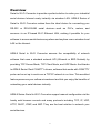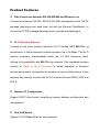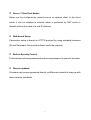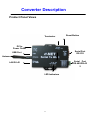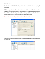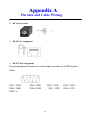
1
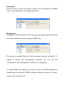
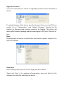
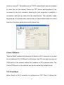
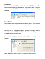
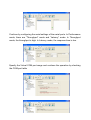
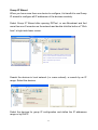
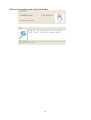
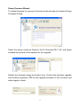
SERIAL TO Wifi CONVERTER E-P132-W User Manual Table of Contents Introduction ……………………………………………………………………3 Overview ………………………………………………………………………….4 Package Check List ……………………………………………………………..5 Product Features ………………………………………………………………..6 Hardware Specifications ……………………………………………………….8 Converter Description ……………………………………………………...11 Product Panel Views …………………………………………………….……..11 Right Side ………………………………………………………………………..12 Left Side ………………………………………………………………………….13 Rear Side …………………………………………………………………………13 LED Indicators …………………………………………………………………..14 Wiring Architecture …………………………………………………………….15 RS-232 …………………………………………………………………………….15 RS-422/RS-485 …………………………………………………………………..15 Serial to Wi-Fi Converter Configuration…………………...………...16 Software Setup and Initial IP Configuration ……………………….……….16 DSTool Software Setup ……………………………… ………………………..17 DSTool Setup ……………………………………………………………………17 Serial to Wi-Fi Configuration ………………………………………….19 Broadcast ………………………………………………………………………..19 Device List ……………………………………………………………………...20 General …………………………………………………………………………...20 Security …………………………………………………………………………..21 Networking ………………………………………………………………………22 1 Wireless ………………………………………………………………………….22 Notification ……………………………………………………………………...23 Management …………………………………………………………………….23 Upgrade Firmware ……………………………………………………………..24 Save/Load ………………………………………………………………………….24 Port ………………………………………………………………………………..25 Serial Settings ………………………………………… ………………………..26 Service Mode …………………………………………………………………....26 Notification ………………………………………………………………………28 VCOM List ………………………………………………………………………..30 Setup Wizard …………………………………………………………………….30 Virtual Com Wizard ……………………………………………………………….30 Serial Tunnel Wizard ……………………………………………………………..32 Group IP Wizard ………………………………………………………………...33 Group Setup Wizard ……………………………………………………………...34 Group Firmware Wizard………………………………………………………….37 IP Collection ……………………………………… …………………………….38 System Log ……………………………… ……………………………………...39 Appendix A - Pin Outs and Cable Wiring……………………….40 DC Power Outlet ………………………………………………………………...40 RJ-45 Pin Assignment …………………………………………………………40 RS-232 Pi Assignment …………………………………………………………40 RS-422 Pin Assignment ……………………………………………………….41 RS-485 Pin Assignment ……………………………………….……...……….41 2 Introduction Serial to WiFi Server is providing new ways of connecting serial converter devices to a Wireless Lan ( WLN ). Serial to Wi-Fi Converter is designed to operate serial ports through wireless ( Wi-Fi 802.11b & g ) or entity line ( RJ-45 cable) over 100Mbit/s Ethernet networks. The data is transmitted via TCP/IP protocol. Therefore control is available via Ethernet, Intranet and Internet. Serial to Wi-Fi Converter is packaged in a case well suited for industrial environments. All serial ports operate in common RS-232 mode , industrial RS-422 and RS-485 modes configuration. Serial to Wi-Fi Converter is a low-cost, high performance design. By careful selecting high quality with competitive prices components in the world, products made network connectivity possible with affordable cost for virtually all kinds of devices. The Series of Serial to Wi-Fi Converter consists of 2 models: E-P132-W ( 1 port for RS-232 / RS-422 / 485 ) and E-P432-W (4 ports for RS-232/422/485). This operation manual will guide you step by step for the various functions of the Serial to Wi-Fi Converter. The following topics are covered in this chapter: Overview Package Checklist Block Diagram Product Features Product Specifications 3 Overview Serial to Wi-Fi Converter is provide a perfect solution to make your industrial serial devices Internet ready instantly via wireless LAN. ARM-9 Series of Serial to Wi-Fi Converter makes them the ideal choice for connecting your RS-232 or RS-422/485 serial devices—such as PLCs, meters, and sensors—to an IP-based Wi-Fi Ethernet LAN, making it possible for your software to access serial devices anywhere and anytime over a wireless local LAN or the Internet. ARM-9 Serial to Wi-Fi Converter ensures the compatibility of network software that uses a standard network API (Winsock or BSD Sockets) by providing TCP Server Mode, TCP Client Mode, and UDP Mode. And thanks to ARM-9 Series’ Real COM/TTY drivers, software that works with COM/TTY ports can be set up to work over a TCP/IP network in no time. This excellent feature preserves your software investment and lets you enjoy the benefits of networking your serial devices instantly. ARM-9 Series Serial to Wi-Fi Converter support manual configuration via the handy web browser console and many protocols including TCP, IP, UDP, HTTP, DHCP, ICMP, and ARP. They are the best solution to network your serial devices. 4 Package Check List Serial to Wi-Fi Converter product is shipped with the following items: □□ 1 unit of Serial to E-P132-W Converter □□ 2 unit of dipole antenna(2.0dBi / 5.0dBi) NOTE: Notify your sales representative if any of the above items is missing or damaged. 5 Product Features Data Conversion between RS-232/422/485 and Wireless Lan Convert serial device (RS-232, RS-422, RS-485) data/signal into the TCP/IP package data/signal and send them out with the Ethernet DataStream; or convert the TCP/IP package data/signal into serial device data/signal. Wi-Fi Wireless Ethernet It based on the latest industry standard Wi-Fi Certified IEEE 802.11b / g specification; it offers maximum channel speeds of up to 54 Mbps. The Wi-Fi function maintains interoperability within the 2.4 GHz frequency band, offering full compatibility with 802.11b / g networks. This integrated wireless solution of Serial to Wi-Fi Converter is widely deployed in business environments and is the standard for wireless access in public places. It also supports key security features like Wi-Fi Protected Access (WPA), WEP and 802.1x. Dynamic IP Configuration Support DHCP client mode, simplifying network address configuration and management. Dual LAN Speed Support 10/100 Mbps Ethernet, auto-detected. 6 Server / Client Dual Modes Series can be configured as network server or network client. In the client mode, it can be installed in network which is protected by NAT router or firewall, without the need of a real IP address. Web-based Setup Parameters setup is based on HTTPS protocol by using standard browsers (IE and Netscape). No special software would be required. Built-in Security Control Protected by both setup password and access password to prevent intruders. Remote updated Firmware can be reprogrammed directly via Ethernet network to keep up with latest network standards. 7 Hardware Specifications WLAN 1. Standard Compliance : IEEE 802.11 b / g 2. Spread Spectrum Technology: DSSS, OFDM 3. Tx Power 11b: Maximum 20 dBm 4. Tx Power 11g: Maximum 18 dBm 5. Rx Sensitivity: -70 dBm @ 54 Mbps, -85 dBm @ 11Mbps 6. Transmission Rate: 54 Mbps (max.) with auto fallback (54,48, 36, 24, 18, 12, 11, 9, 6, 5.5, 2, 1 Mbps) 7. Transmission distance: Up to 300 feet (@12 Mbps, in open areas) 8. Security: WEP 64-bit/128-bit data encryption, AES, WPA2 9. Antenna Connector: Reverse SMA 10. Network Mode: Infrastructure, Ad-Hoc LAN for configuration / Ethernet hub 1. Ethernet: 10/100 Mbps, RJ45 2. Protection: Built-in 1.5 KV magnetic isolation Serial Communication Parameters 1. No. of ports : 1 * RS-232/422/485 port, male DB9, S/W selectable 2. RS-232 Signals : TxD, RxD, RTS, CTS, DTR, DSR, DCD, GND 3. RS-422 Signal : Tx+ , Tx- , Rx+ , Rx – 4. RS-485 Signal : Data+ , Data5. Serial Line Protection : 15 KV ESD for all signals Beeper for event warning or unit positioning ( Optional) 8 Serial Communication Parameters 1. Parity: None, Even, Odd, Space, Mark 2. Data bits: 5, 6, 7, 8 3. Stop bits: 1, 1.5, 2 4. Flow control: RTS/CTS, XON/XOFF 5. Speed: 110 bps to 460.8+ Kbps Power Requirements 1. Power input 1: 12 VDC 2. Power Line protection : 1 KV Burst (EFT), EN61000-4-4 0.5 KV Surge, EN61000-4-5 Environmental 1. Operating Temperature : -10 to 70°C (32 to 131°F), 5 to 95% RH 2. Storage Temperature : -20 to 85°C (-4 to 185°F), 5 to 95%RH 3. Regulatory Approvals RoHS EMC: FCC Class A, CE Class A Safety: UL, CUL, TÜV Class I, DIV II Software Features 1. Protocols : ICMP, IP, TCP, UDP, DHCP, BootP, ARP / RARP, Telnet, RTelnet, DNS, SNMP MIB II, HTTP, SMTP, SNTP 2. Serial mode : Virtual Com / TCP Server / TCP Client / UDP / Serial Tunnel with advanced settings of TCP Alive Check Timeout Inactivity Timeout Delimiter for Data Packing 9 Force TX Timeout for Data Packing 4 Hosts simultaneous connection : Virtual Com / TCP server / TCP Client (only raw data) 1. Security: HTTPS, SSH v2 2. Event notification by email / SNMP trap SNMP Trap Cold/Warm Start DSR, DCD Changed IP Changed Authentication Fail SNMP Response System MIB, Interface MIB, ICMP, IP, TCP MIB UDP MIB RS-232 MIB 3. Utilities : Windows NT/2000/XP/2003/VISTA Device discovery Auto IP report Device setting (run-time change, no rebooting) Access control list Group setting Device monitoring Serial port monitoring Log info Group Firmware update batch Virtual COM/TTY Drivers (WDM mode, configuration in windows device manager) : Windows NT/2000/XP/2003, VISTA 10 Converter Description Product Panel Views Terminator Reset Button DC-In Power Outlet Serial Port RS-232 USB Port Antenna Serial Port RS-485/RS-42 2 LAN RJ-45 LED Indicators 11 Right Side DC-In Power Outlet The Serial to Wi-Fi Converter is powered by a single 12V DC(Inner positive/outer negative) power supply and 1.0mA of current. A suitable power supply adapter is part of the packaging. Connect the power line to the power outlet at the right side of Serial to Wi-Fi Converter and put the adapter into the socket. If the power is properly supplied, the “SYS” green color LED will be on Antenna USB Port DC-In Power Outlet Ethernet Port USB Port The USB port is for wireless USB dongle. Antenna Connector The connector for antenna is a standard reverse SMA jack. Simply connect it to a 2.0dBi or 5.0dBi dipole antenna (Standard Rubber Duck) and it is 50 Ohms impedance and can support 2.4GHz frequency. Ethernet Port The connector for network is the usual RJ45. Simply connect it to your network switch or Hub. When the connection is made, the LAN LED indicator will light. When data traffic occurs on the network, red (Rx/Tx) indicator will blink during data transferring and receiving. 12 Left Side RS-485/RS-422 RS-232 Serial I/O Port of RS-232/RS-422/RS-485 Connect the serial data cable between the Wi-Fi converter and the serial device. Follow the parameter setup procedures to configure the converter (see the following chapters ). Rear Side Reset Button Terminator Reset Button If by any chance, you forget the setup password, or have incorrect settings making e-Net TCP/IP converter inoperable. First, turn on the power and wait the sys led light . Second, use any point tip to push this button and hold it and wait for 3 second. All the parameters will be reset to the factory default ( default ip: 192.168.10.2). 13 Terminator The purpose is for compensating signal attenuation in long distance connection at RS-485/RS-422 I/O. If the switch 1 & 2 are set in “ON” position, the signal compensation will be activated. To disable the function, just push switch 1 & 2 to opposite position. LED Indicators LAN (Green) Network signal indicator (When the LAN signal is detected, the LED will be on.) WLAN (Green) Wireless Lan indicator ( When wireless Lan signal is connected, the LED will be on ) TX / RX (Green) Data sent indicator (When data are sent out to the network, the LED will be on.) Data received indicator (When data are received from the network, the LED will be on.) SYS (Red) Power indicator (When the power is on, the LED will blink once per second.) 14 Wiring Architecture RS-232 Wiring Architecture RS-422/RS-485 Wiring Architecture When you finish the steps mentioned above and the LED indicators are as shown, the converter is installed correctly. You can use the Software Setup CD to setup the IP Address. To proceed the advanced parameter setup, please use a web browser (IE or Netscape) to continue the detailed settings. 15 Serial to Wi-Fi Converter Configuration Software Setup and Initial IP Configuration When setting up your converter for the first time, the first thing you should do is configure the IP address. This chapter introduces the method how to install the program and how to configure the serial to Wi-Fi Converter device’s IP address. For quick and easy start , We suggest you to reference “Quick Installation Guide” manual. The following topics are covered in this chapter: DS Tool Software Setup Serial to Wi-Fi Converter Configuration Converter Configuration through Web 16 DS Tool Software Setup On PC we provide a Device Management Utility named DS Tool which is an executable program in Windows 32 bit environments. DS Tool Setup is used to detect and setup the installed converter. It uses UDP broadcast packets to query and configure converters on the network. DSTool Setup Insert the CD and select “DSTool_ODM_Setup”,folder and double click “DSTool_ODM_Setup.exe”, runing to install Windows utility. When the “installing DSTool” screen is pop-up then double click the “Start” icon for installing. 17 1.1 After finishing installation, the “installation was completed successfully” screen will be pop-up and jus double click the “OK” icon. 1.2 Coming the screen is for choosing to run “Launch DSTool Now” or “Launch DSTool Later” 1.3 If you choice the item of “Launch DSTool Now” then the DSTool of Device Configuration manual screen will be pop-up. 18 Serial to Wi-Fi Converter Configuration Broadcast After finishing DSTool installation and lunch the DSTool, you can double click the “Broadcast” button at left side upper corner. It will detect the existence of the installed converters on the network. Select the converters you wish to add and double click “Add” button. The table will depict the converters’ status such as IP address, MAC Address, Device Name and status. 19 Device List In the Device List icon, you will find the added converter in the list and double click on the device will continue to configure other rest of the converter settings. General After listing of device IP in “Device List” item, You can click the IP as show on table then the General section lists information as “Model”, “IP Address”, and “MAC Address”, “Firmware Version” “Device Name/Location“ and device working status … etc. You can configure some parameters and modify device name and location The item of “Using SNTP Time Server” 20 Security Serial to Wi-Fi converter’s Security includes access IP & Mask list table and administration security. The Access IP Table specifies the IP address and subnet that can access to the device. The access is based on IP and Mask combination. If the access is open to all hosts, do NOT enable this function. For administration security, You can assign a password for administrator’s management and also to prevent others who are unauthorized to the configurations on the device. If you assign a password, you will need to manage it(Depend on your policy). When you access Windows, Web, or Telnet consoles and it also is validated to “Setup Wizard configuration” function. After modifying configuration, be sure to validate the changes by using “Apply Only” or “Apply and Save”. 21 Networking Serial to Wi-Fi converter can support both type of IP such as Static IP or DHCP/BootP IP configuration. After modifying configuration and click the icon of “Apply Only” or “Apply and Save” for finishing IP configuration. Wireless You can use the wireless item for configuring Serial to Wi-Fi Converter’s Wi-Fi parameters. “SSID Scan” is for searching the available wireless access point and select your AP device. “Wireless Encryption” is for setup parameters as encryption type and key, be sure to validate the changes by using “Apply Only” or “Apply and Save”. 22 Notification Serial to Wi-Fi converter can support 3 ways of event notification as “SNMP Trap”, “Email Notification” and Syslog Notification. Management In addition to DSTool, Serial to Wi-Fi Converter can also be managed by Web and Telnet consoles as well as supports SNMP trap. The device is enabled Web and Telnet consoles functions by default. To enable or disable the management consoles, you can use the “Configuration” and “Management” of DSTool for configuring. To enable SNMP trap support, you have to check the SNMP Management Enable device and specify SNMP settings including Community, Location, Contact, and Trap Server IP. 23 Upgrade Firmware You can contact with your vendor for upgrading the latest version firmware of device. To update firmware of the device, save the firmware file in your host PC from vendor. Go to “Configuration”, and “Update Firmware”. Specify the file location by Browsing and continue operation by Update. The device will reboot after firmware updating and be located again in DSTool’s “Device List” item. Note: All parameters will restore to default after the firmware update, except for the device IP address. Save/Load After finishing setup, be sure to click “Apply and Save” button. “Apply and Save” is for applying all parameters save and flash but the changes are valid after rebooting the device. 24 “Load default” is all parameters changes to factory’s default except network setting. “Reboot Device” is for rebooting device and needs to broadcast again to search the device. “Import” is for retrieving saved configuration file to apply in current device. “Export” is saving the current parameters onto a file and export to a current host for saving. Port Port Configurations is for configuring as serial parameters, serial communication modes, data packing options, and event notifications. Serial Settings Port Alias : Remark the port to the connected device. Baud rate : from 110bps to 460.8kbps Parity : No, Even, Odd, Mark, Space Data Bits : 5, 6, 7, 8 Stop Bits: 1, 2 (1.5) 25 Flow Control : No, XON/XOFF, RTS/CTS, DTR/DSR Interface : RS232 Performance : “Throughput”, guarantees highest transmission speed. “Latency”, guarantees shortest response time. Delimiter Settings For advanced data packing options, you can specify delimiters for Serial to Ethernet and / or Ethernet to Serial communications. You can define 4 delimiters (00~FF, HEX) for each way and until the delimiters are received, the data will not transmit success. “Flush Ethernet to Serial Data Buffer After” is for counting the flush times out of data transmitted between Ethernet and Serial. “Force TX interval time” is for specifying the timeout when no data has been transmitted and the timeout is reached or TX buffer is full (4K Bytes), the queued data will be sent. If you want to disable and the parameter is setting “0”. (factory default) Service Mode UDP Mode When device is configured as TCP Server, it gives the connected serial 26 device a unique IP : Port address on a TCP/IP network that it can be accessed by other host on the network. Device as TCP Server waits passively to be contacted by the host computer, allowing the host computer to establish a connection with and get data from the serial device. This operation mode supports up to 5 simultaneous connections, so that multiple hosts can collect data from the same serial device at the same time. Virtual COM Mode “Service Mode” enables the serial port in Serial to Wi-Fi converter to act and be controlled as PC’s COM port for Windows. One PC can have as many as COM ports on the network without the limitation of PC’s physical slots. The Virtual COM ports on the network can also be shared by multiple hosts. TCP Client Mode When Serial to Wi-Fi converter is configured as TCP Client, it allows the 27 connected serial device the ability to initiate actively the TCP connection to remote host software when it needed. When the connection is built, the data is transmitted bi-directionally and till the data transmission is finished, the TCP connection will be closed by TCP Client. The connect-on-demand TCP Client operation helps the host computer to manage high number of remote devices that exceeds the maximum simultaneous TCP connections allowed. Serial to Wi-Fi converter supports up to 5 simultaneous TCP Client connections for redundant system considerations Notification Port status can be notified to administrator by email, SNMP trap, or System Log. There are several events of notification include: DCD changed: When DCD (Data Carrier Detect) signal changes, indicating the modem connection status has changed, the event will be triggered. RI changed: When RI(Ring Indicator) signal changes, indicating the incoming of a call, the event will be triggered. 28 DSR changed: When DSR (Data Set Ready) signal changes, indicating that the data communication equipment is powered off, the event will be triggered. CTS changed: When CTS (Clear To Send) signal changes, indicating that the transmission between computer and DCE can proceed. Port connected: In TCP Server Mode, when the device accepts an incoming TCP connection, this event will be trigger. In TCP Client Mode, when the device has connected to the remote host, this event will be trigger. In Virtual COM Mode, when Virtual COM is ready to use, this event will be trigger. Port disconnected: In TCP Server/Client Mode, when the device lost the TCP link, this event will be trigger. In Virtual COM Mode, When Virtual COM is not available, this event will be trigger. To enable activate the notification, specify the event type and the notification methods. The details of SNMP trap Server, Email SMTP server, or Log server IP should be configured first properly “Management”. 29 in device “Configuration” VCOM List You can monitor the COM port status from the “VCOM” function. The monitored items can also be defined by the “Select Monitor Items” at right side of upper corner. The COM ports must be configured first before monitoring the status Setup Wizard DSTool offers 5 Setup Wizards to help you manage Serial to Wi-Fi Converter devices as a group and streamline the management tasks. Virtual COM Wizard DSTool offers one of the easiest way to add serial COM ports over the network by the Virtual COM Wizard. Serial to Wi-Fi Converter COM port driver is installed when you install DSTool . Select the Virtual COM Wizard from Setup Wizard. There are only 3 steps to follow up. Select the available ports of Serial Wi-Fi Converters on the network. 30 Continue by configuring the serial settings of the serial ports. In Performance mode, there are “Throughput” mode and “Latency” mode. In Throughput mode, the throughput is high. In Latency mode, the response time is low. Specify the Virtual COM port range and continue the operation by checking the COM port table 31 Serial Tunnel Wizard The Serial Tunnel Wizard gives you the option to transparently pair two devices over the network. Select the devices that should be paired and move the devices into IP1 and IP2. After configuring the serial setting of the ports, the serial tunnel will be built by assigning one port as the TCP Server mode and the other as the TCP Client mode. 32 Group IP Wizard When you have more than one device to configure, it is handful to use Group IP wizard to configure all IP addresses of the devices remotely. Select Group IP Wizard after opening DSTool, or use Broadcast and find more than one Converters on the network and double click the button of “Click here” at right side lower corner. Search the devices in local network (i.e. same subnet), or search by an IP range. Select the devices Select the devices for group IP configuration and define the IP addresses range or by DHCP. 33 Click next to confirm the setup and the IP configuration is finished, you will see the IP addresses for the devices Group Setup Wizard Group Setup Wizard can be help you to copy the configuration of one device to other converters. You can select the items to be copied or not. Go to “Setup Wizard”, “Group Setup Wizard”, and choose “Next” to continue. 34 Select device model as “Serial Server DS-11-W”. Select the source device for the configuration and destination devices. 35 Click next to confirm and finish the wizard. 36 Group Firmware Wizard To update firmware for a group of devices can be as easy as 4 steps of Group Firmware Wizard Select the device model as Serial to Wi-Fi Converter DS-11-W, and select available converters on the network for the upgrade Specify the firmware image and select next. Confirm the firmware upgrade and continue operation. DSTool will upgrade firmware of the converter and reboot again to finish 37 IP Collection For the dynamic DHCP IP settings, it is often a task to find the changing IP addresses DSTool supports auto IP report function to report the current IP address of the Serial to Wi-Fi converter units to administrator. To enable the function, check “Auto IP Report” in “Configuration”, “General”. Specify the host that the device should report IP to, or define current host as the report host. Be sure to define the Report Interval time. Zero is disable Go to the IP Collection function of the main menu and find the converters auto IP report list 38 System Log You can use a calendar at the button of “System Log” screen for searching the history data of log massages. 39 Appendix A Pin outs and Cable Wiring □□ DC Power outlet □□ RJ-45 Pin Assignment □□ RS-232 Pin Assignment The pin assignment scheme for a 9-pin male connector on a DTE is given below. PIN 1 : DCD PIN 5 : GND PIN 9 : X PIN 2 : RXD PIN 6 : DSR PIN 3 : TXD PIN 7 : RTS 40 PIN 4 : DTR PIN 8 : CTS □□ RS-422 Pin Assignment The pin assignment scheme for a 4-pin RS-422 is given below. 1 2 3 4 PIN 1 : R- PIN 2 : R+ PIN 3 : T- PIN 4 : T+ □□ RS-485 Pin Assignment The pin assignment scheme for a 4-pin RS-485 is given below. 1 PIN 1 : X 2 PIN 2 : X 3 4 PIN 3 : D+ PIN 4 : D- Please visit our website http://www.tcpipweb.com.tw/ for more detail information . 41