1
IC-W1 User Manual
1 Introduction
IC-W1 User Manual
1 Introduction
The IrrigationCaddy IC-W1 (IC) is a WiFi enabled irrigation controller. The IC allows the
user to control and schedule an irrigation system from any computer with a web browser.
No special software or clients are required, just a Web Browser on a computer
or internet enabled device.
The IC can be used in new installations or as a replacement for an existing sprinkler control
system.
The IC supports up to 11 different irrigation zones on the main unit, and it can be expanded
up to 43 irrigation zones by adding expansion modules (ICExpanders). If your system uses
a master valve, one of the outputs will be used as the master valve control, thus allowing
only a maximum of 10 zones if using only the main unit, and up to 42 if fully expanded.
Out of the box the IC is configured with output #11 set as the master valve output, this can
be changed, and the master valve control disabled by disabling the master valve control setting in the Settings -> Other section.
2
2 Mounting on the Wall
2.1 Steps:
1. Find an appropriate location for the IC, and hold the enclosure in place.
2. Using a pen make marks through the screw mounting holes (C) on the plastic ears
protruding from the enclosure.
3. NOTE: If installing on Drywall make sure you use screw anchors
4. Put the device aside, and drill a hole on each one of the marks you made.
5. Put the IC back in place and insert the screws through the mounting holes.
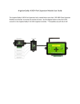
A. WiFi Antenna
B. Expansion Port
C. Mounting Ear
D. Ethernet Port
E. USB Port
F. Flow Sensor Port
G. Rain Sensor Port
H. Valve wire connector
3
IC-W1 User Manual
2 Mounting on the Wall
2 Mounting on the Wall
IC-W1 User Manual
I. Power Connector
J. Power light indicator
K. Activity Indicator
L. LCD Screen
4
3 Connecting Valve Wires
IC-W1 User Manual
3 Connecting Valve Wires
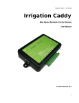
3.1 Steps:
1. If this is a replacement installation, first remove the old Sprinkler Control System,
and attach the IC to the wall. Make sure the valve cables can reach the IC.
2. Identify the common cable and connect it to the “com” output.
3. Connect valves 1 through 10, to the corresponding outputs on the IC
4. If your installation includes a master valve, connect the master valve to output #11
(“11 | MV”).
5. Connect the power cable to the IC using the “AC1” “AC2” (I) outputs using the connector provided.
6. Plug the wall transformer to a power outlet.
7. The IC should now be installed, and ready to be configured.
5
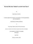
4 Connecting to the Network
When you first apply power to the IC, the IC will boot up and broadcast a WiFi SSID called
“IrrigationCaddyAP”. This SSID will allow you to gain access to the unit, and configure it
so that you can connect it to your own WiFi network ( Router ). Follow the connection steps
appropriate for your platform.
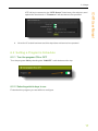
4.1 Windows 7 Connection Steps
4.1.1 Steps:
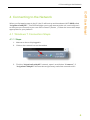
1. Make sure the unit is plugged in.
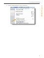
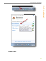
2. Click on the network icon on the taskbar
3. Find the “IrrigationCaddyAP” network, open it, and click on “Connect”. If
“IrrigationCaddyAP” does not show right away, wait a few seconds until it
6
IC-W1 User Manual
4 Connecting to the Network
4 Connecting to the Network
IC-W1 User Manual
shows up. You might have to repeat step 2 to refresh the networks
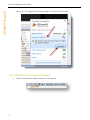
4.2 MAC OS X Connection Steps
1. Click on the Wireless Signal indicator on the top bar
7
4 Connecting to the Network
IC-W1 User Manual
2. Find the “IrrigationCaddyAP” network, and select it.
8
4 Connecting to the Network
IC-W1 User Manual
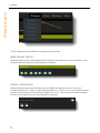
4.3 Connect Caddy to your Router
1. Once you have connected to the SSID, open a web browser and navigate to
http://169.254.1.1 (You might have to wait up to 30 seconds before you are able
to access the page after connecting to “IrrigationCaddyAP” SSID. Refresh the
page until it connects)
2. Now you are connected to the IrrigationCaddy SSID, however the objective
should be to connect the IC to your own WiFi network SSID, so that you can
access the IC like any other networked device you might own.
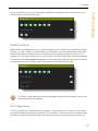
3. On the menu bar click on “Setup” and then “Settings”
9
4 Connecting to the Network
IC-W1 User Manual
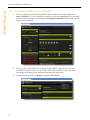
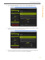
4. Open “Network Settings”, and click on the “Scan Networks” button.
5. When the scan finishes, it will display a list of available network SSIDs. Click on
your preferred network SSID to connect to it.
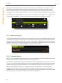
6. If the network SSID is protected, you will be prompted to enter a passphrase.
Enter the passphrase and click on “Connect to Network”.
10
4 Connecting to the Network
IC-W1 User Manual
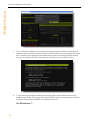
7. The IC will then display a reconnection message, and it will reboot. When the IC
reboots it will try to reconnect to the new network SSID you just selected. Now you
can reconnect your laptop/PC/portable device to the new network SSID so that
you can access the IC in the new network (usually your home WiFi router).
2. To go back to the original network once again click on the network icon on the
taskbar, and select your preferred network SSID, which in most cases it would be
the same as the network SSID you selected for the IC.
On Windows 7:
11
4 Connecting to the Network
IC-W1 User Manual
On MAC OS X:
12
4 Connecting to the Network
IC-W1 User Manual
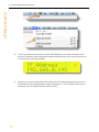
8. The IC would have rebooted, and the LCD display on it would now show a different IP address, which would have been obtained from the router you just connected it to by selecting its SSID.
9. Now you can open a Web Browser and put the IP address displayed on the ICs
LCD display, in the address bar to start using the IC.(The IP shown above is an
example, your IC will likely show a different IP)
13
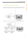
5 Connecting Expansion Modules
The IC-W1 zone capacity can be expanded to up to 43 zones by adding expansion modules (EXP-800). The expansion modules connect into the “Expansion Port” for the IC-W1.
Up to 4 expansion modules can be used by adding an expansion module hub (H-500).
14
IC-W1 User Manual
5 Connecting Expansion Modules
6 Usage
Going to the http://irrigationcaddy web address will present you with a Web Interface to
the IC.(NOTE: If the hostname does not work ("irrigationcaddy"), use the IP Address
which is displayed on the LCD screen on the device)
The IC is capable of scheduling irrigation times using five different programs, which can be
scheduled independently. The IC also provides the user with a “Run Now” program,
which allows the user to execute a one time schedule, immediately after programming.
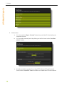
6.1 Setting the Clock
It is important that you set the IC's clock time to the current time.
6.1.1 Steps:
1. Click on “Settings”.
2. Click on “Clocks”.
15
IC-W1 User Manual
6 Usage
6 Usage
IC-W1 User Manual
3. Set the time:
a. You can use the “Sync Clocks" button to synch the IC’s clock with your
computer’s clock.
b. You can also manually set it by clicking on the field next to the “Set Datetime” button.
c. It is also possible to set the time using NTP (Network Time Protocol).
Click on the “Use NTP Time” checkbox to enable the NTP time feature.
16
6 Usage
4. Once the IC’s clock has been set, this step does not have to be repeated.
6.2 Setting a Program’s Schedule
6.2.1 Turn the program ON or OFF
Turn the program ON by checking the “ON/OFF” radio buttons at the top.
6.2.2 Selecting which days to run
First select the program you would like to configure.
17
IC-W1 User Manual
NTP will try to connect to the “NTP Server” listed every few minutes, and
update the local clock. A “Timezone” will also have to be specified.
6 Usage
IC-W1 User Manual
The IC supports several different programming schemes
IN D IVID U AL D AYS
With this scheme you set what days of the week you would like to run your sprinklers. The
program will then start only on the days you selected.
EVEN / OD D D AYS
With this scheme you select whether you would like the system to run on only even
numbered days (2, 4, 6 etc) or odd numbered days (1, 3, 5 etc). Then you would select the
individual week days you would like the system to run on. This way you can tell the system
to run on even days, but not on weekends for example.
18
6 Usage
IC-W1 User Manual
If you would like to run even or odd days regardless of what day of the week it is then you
would select every day of the week.
EVER Y N D AYS
With the Every N Days option you can tell the system to run exactly every specified number
of days (i.e. every 3 days). As with the Even / Odd option, you can combine this option with
the individual days, and also restrict which days of the week the system should run. For
example you can tell the system to run every 2 days except for Mondays, and Wednesdays.
You can use the "Days before next run" to move the starting day forward into the future,
as opposed to the current day, which is the default if this setting is not used.
The Even / Odd Days and Every N Days options cannot be combined. Once one is
selected the other is disabled.
6.2.3 Start Times
The IC provides up to 5 start times per program. The start times are used to run the same
program at different times during the day. For example, in certain scenarios it makes sense
to water the same areas twice a day, once early in the morning and once later in the day.
19
6 Usage
IC-W1 User Manual
This can be accomplished by enabling one extra start from start times number 2, 3, 4 or 5.
Start time 1 is always enabled, and it is the default start time. In other scenarios, where
water runoff is a concern, the programs can be shortened, but more start times can be
enabled thus maintaining the total amount of water output desired, while preventing runoff.
To select the program’s start time click on the text field below the “Start Time” heading, and
a time picker will display. Then select the start time using the up and down controls.
6.2.4 Seasonal Adjust
The Seasonal Adjust feature allows you to increase or decrease the watering time by a percentage of the schedule's total time. For example in winter you might want to decrease the
amount of total watering being done, without changing the relative amounts that each zone
receives, and without having to change each of the zone's assigned run times. In that case
you can use the Seasonal Adjust slider to adjust the total run time.
6.2.5 Weather Adjust
NOTE: For the Weather Adjust feature to work, the caddy must be connected to the Cloud,
otherwise the caddy is not able to retrieve the weather data.
The Weather Adjust feature allows the caddy to retrieve precipitation information from the
Cloud. You can then tell the caddy how to use the precipitation data, and thus decrease the
amount of watering that should be done. For example if it rained in the last 24 hours it is
likely you would like the caddy not to water as much. In that case you can use the precipitation data being retrieved, and allow the caddy to water a lesser amount, if the precipitation is more than a certain value. For example "If it rained more than 0.53 inches in the
last 24 hours, then only water 50% of the total time scheduled".
20
6 Usage
IC-W1 User Manual
En a b l e / D i sa b l e We a th e r Ad j u st
By default the Weather Adjust feature is disabled. In order to enable it you must switch the
"Use Weather Adjust" option from "NO" to "YES".
Once the "Use Weather Adjust" option is set to "YES", the area would expand to display the
full set of controls.
21
6 Usage
IC-W1 User Manual
6.2.6 Setting zone run times
To set the zone run times, under the “Run Times” heading, move the slider to the right to
increase the amount of time a zone should run. The run time will display on top of the slider.
1. Minimum time boundary
2. Maximum time boundary. The zone cannot be set to run for more than the high
time boundary. This limit can be changed from the settings page.
3. The slider.
4. The amount of time the zone will run.
6.2.7 Using the “Run Now” Program
The "Run Now" program allows you to run the system at the current moment. Just set the
duration times on each one of the zones you are interested in running, and click on the
“Run Now” button. This will start the system immediately.
22
6 Usage
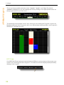
The status area is divided into sections.
1. The first section indicates whether the system is ON or OFF, and it allows the user
to turn the system ON or OFF. Turning the system OFF means that the scheduler
will not run and therefore the programs will never execute. However the device
will continue to answer to network requests as usual.
2. The next section indicates the run time remaining for a program and for the zone
currently running within that program. It also allows the user to stop the running
program or zone.
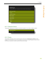
3. The next section is a global status area for the zones. Bright Green will display for
a zone currently running, Muted Green / Brown is for a zone that will run in the
future after the zones above it have finished running, and Red indicates the zone
has already run, or the zone will not run at all.
23
IC-W1 User Manual
6.3 Status Area
6 Usage
IC-W1 User Manual
4. The next section indicates the Cloud service connecton status.
5. The next section shows the rain totals.
24
6 Usage
IC-W1 User Manual
6. The next section indicates the rain sensor status.
7. The next section indicates flow sensor status.
6.4 Calendar
You can see a visual representation of when the programs will run by clicking on the "Calendar" link.
25
6 Usage
IC-W1 User Manual
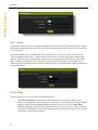
There are three possible calendar views, "month", "week", and "day". By default
"month" will display but you can change the view by clicking on the appropriate button on
the top right hand corner of the view.
The following is an example "week" view, where you can clearly see Program 1 will run on
Monday starting at 6am, Program 2 will run on Wednesday starting at 8am, and Program 3
will start on Thursday at 12pm.
6.5 Log
If a USB Flash Drive has been inserted into the USB port, and you have a flow sensor connected, the unit will log its water usage to it. The data can then be displayed and plotted by
clicking on the Log link.
26
6 Usage
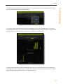
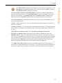
The chart on the top will show the water usage per hour for the day selected. The hours
are displayed from 0 to 23. The bottom chart displays the total water usage per day for the
whole month. The Month is the month for the day you have selected.
Clicking on the bar for the day, will change the chart on the top for the hours for each day,
showing the water usage by hour. This way you can see the detail usage by hour for each
day simply by clicking on the bar for the day of interest.
27
IC-W1 User Manual
The top section will allow for a date selection, so navigate through the log data. When the
log is opened it defaults to the current day.
6 Usage
IC-W1 User Manual
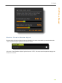
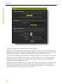
6.6 Settings
The settings page can be accessed by clicking on the "Settings" link.
Once you access the settings page the system settings are subdivided into sections.
28
6 Usage
IC-W1 User Manual
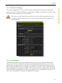
6.6.1 Firmware Version
This section displays the firmware version the system is currently configured with.
6.6.2 Clocks
The section allows the user to set the system clock (see "Setting the Clock" under
Usage). The clock will not sync if a program is running; the only exception to this rule is if
NTP time is enabled; in which case the clock will change.
29
6 Usage
IC-W1 User Manual
There are 3 different ways of adjusting the internal clock.
The first is by syncing the computer time (the computer you are accessing the caddy from),
with the internal clock. Clicking on the "Sync Clock" button will sync the computer time displayed above the button, with the internal clock time displayed below the button.
The second way is manual. By clicking on text field pointed by the "Pick a Date / Time" label,
a date time picker will display allowing you to select the date and time. After selecting the
date and time you can click on the "Set Datetime" button, and the internal clock will be
synced with the date and time selected.
The last way is NTP (Network Time Protocol). NTP relies on an Internet connection, therefore if the IC cannot access the internet, this method will not work. NTP must access a
server on the Internet in order to retrieve accurate time information. The IC will request
time information from the server every 10 minutes.
30
6 Usage
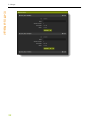
The section displays the current network system settings and also allows for setting the
hostname, DHCP or Static IP address configuration, IP Address (if static was chosen), port
number, default gateway, and network mask.
Unless you are proficient with network terms, and understand how devices communicate in an Ethernet network, it is recommended that you don’t change the
default settings.
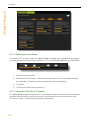
6.6.4 Zone Blocks
This section shows the connected expansion blocks if any. Each expansion block is identified by an ID, and an optional Name. Each block also indicates how many zones it has,
and whether the block is active or inactive. Once a block is connected to the main unit, the
block registers itself with the unit, and the main unit will remember it. If the expander is then
disconnected the block will show as INACTIVE in this section. The Nudge button allows the
user to identify the expander if more than one expander is connected to the main unit. The
ACT led on the expander will flash red rapidly when nudged.
31
IC-W1 User Manual
6.6.3 Network Settings
6 Usage
IC-W1 User Manual
32
6 Usage
IC-W1 User Manual
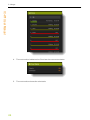
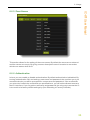
6.6.5 Zone Names
This section allows for the setting of the zone names. By default the zones are numbered
and the names are empty. By giving a zone a descriptive name it is easier to remember
which zone waters what area.
6.6.6 Authentication
In here you can enable or disable authentication. By default authentication is disabled. By
turning authentication ON, and setting a username and password, the next time you try to
access the device you will be prompted for a username and password. If the credentials
you enter don’t match the credentials you specified here, you will not be allowed access to
the IC’s interface. If you forget the username and password, the only way to access the IC
is to reset it to its factory default settings by (See Resetting to Factory Defaults).
33
6 Usage
IC-W1 User Manual
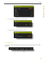
6.6.7 Cloud
This section allows you to connect the caddy to the Cloud service. The section has a switch
to enable or disable the cloud feature, as well as 2 separate fields for the "API Key" and the
"Controller ID".
Before the caddy can connect to the Cloud service, you must first create an account at
"cloud.irrigationcaddy.com". Follow the directions there on how to link your caddy to the
service. Once the account has been created and configured with a caddy in it, you will be
able to obtain an API Key and a Controller ID that can be entered in these fields. Enter
those values in the fields and enable the switch and save, and the caddy will then connect to
the Cloud service.
6.6.8 Other
This section is reserved for other unrelated settings.
l
34
"Use Rain Sensor" is intended to be used with a rain sensor. When a rain
sensor is plugged into the rain sensor connector, you can use this setting to tell the
system whether it should pay attention to the sensor or not. If the "Use Rain
Sensor" setting is checked the system will check for a rain sensor, and if a sensor
is present, it will water or stop watering according to the sensor state. If the sensor
is wet, the system will not water.
6 Usage
l
l
l
l
l
l
l
"Check if Rain Sensor is Normally Open" is used to tell the IC that the rain
sensor connected to the IC is a "Normally Open" type rain sensor. There are 2
types of rain sensors; "normally close" and "normally open". If the sensor
attached is of the "normally close" type then leave this setting unchecked.
"Use Flow Sensor" should be selected when a flow sensor is available and can
be connected to the IC.
"Units". If a flow sensor is in use, you can select the water usage is reported, in
Liters or in Gallons.
"Units per Pulse". The IC supports pulse based flow sensors. This settings tells
the IC how to translate each pulse into units. Does each pulse mean 1 Gallon? Or
2? etc.
"Flow Rate Average Period". See "Flow Meter Settings" on page 40
"Use #11 as Master Valve" provides for the ability to dedicate a zone as a
"Master Valve". This means that if this setting is checked, every time a regular
zone turns on, the #10 zone will also turn on. This zone can also be used to trigger
a pump start relay. In systems where a water pump is used, a pump relay can be
connected to zone #10 while this setting has been enabled. Every time a zone
turns on due to the schedule, the pump relay would get triggered.
The "Max Zone Run Time" setting is intended to globally limit the maximum
amount of run time that a zone can be set at. The main purpose of the setting is to
prevent programming mistakes and avoid unintended long periods of watering.
35
IC-W1 User Manual
The "Run Now" program is excempt from the effects of this setting. The
"Run Now" program will water even if the rain sensor is WET, and the
"Use Rain Sensor" setting is enabled.
6 Usage
IC-W1 User Manual
6.7 Manual Control
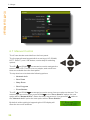
The IC can also be controlled from the front panel.
The front panel has a keypad with 4 arrow keys (UP, DOWN,
LEFT, RIGHT), and 1 OK button, used mainly for selecting
options.
The UP and DOWN
arrows can be used to navigate the
menu on the LCD. The menu is very simple, and not all functions are available from the front panel.
The top level menu includes the following options:
l
Network Info
l
Run Zone
l
Stop Zone
l
Run Program
l
Zone Status
The UP and DOWN
arrows can be used to move from one option to the next. The
menu wraps around so if you press DOWN
on the "Zone Status" option, the next
option will be "Network Info"; Same the other way around, if you press UP while on
the "Network Info" option the next option will be "Zone Status".
By default, while nothing is happening the LCD display will
show the current IP address.
36
6 Usage
IC-W1 User Manual
Pushing on the RIGHT
button while on the IP address
screen will display the MAC address screen.
Pushing on the UP or DOWN
buttons while on the IP address or MAC address
screens will start the menu selection.
6.7.1 Network Info
Pushing OK while pointing to the "Network Info" menu
option goes back to the IP address screen.
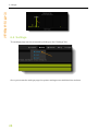
6.7.2 Run Zone
Pushing OK on the "Run Zone" menu option will allow you
to run an individual zone. After pressing OK a new screen is
shown where you can select the zone number to run and the
amount of time to run it for. The time defaults to 15 minutes.
While on the zone selection screen you can use the LEFT
and RIGHT
buttons to navigate from selecting the zone
number, the hours and minutes.
After selecting the zone number, hours and minutes you can press OK to start the zone.
At this point the screen will change and display the "Zone Status" screen.
6.7.3 Stop Zone
Pushing OK while on the "Stop Zone" menu option has the
effect of stopping the currently running zone if any. If no zone
is running nothing happens.
6.7.4 Run Program
Pushing OK while on the "Run Program" menu optino
allows you to run an already scheduled program.
The LCD screen changes to the program selection screen
where you can select the program number to run, from 1 to 5.
6.7.5 Zone Status
The "Zone Status" menu option shows you the current run
status for the system. If a zone is currently running it will display
the zone number for the zone that is currently running as well
as the remaining time.
37
6 Usage
IC-W1 User Manual
The remaining time will tick downwards towards 0; at which point the zone will stop and the
screen will go back to the "Network Info" screen.
38
7 Rain Sensor
The IC supports most "normally close" or "normally open" rain sensors. The sensors could
be wired or wireless. Pretty much any standard off the shelf rain sensor will work.
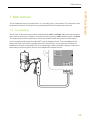
7.1 Connecting
The IC has 1 rain sensor port with 2 outputs labeled RS1 and RS2. Also most rain sensors
have 2 wires coming out of them. One of those wires goes into RS1 and the other into RS2.
The outputs don't have a polarity so it does not matter which wire goes to which output.
It is very important that the wires do NOT have a voltage in them. This can happen if the
sensor wires are somehow connected to the common wire. It is a common practice for
installers to do this, so specially if the IC is replacing an older controller, that you make sure
the sensor is not energized, and not connected to the common wire.
39
IC-W1 User Manual
7 Rain Sensor
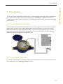
8 Flow Meter
The IC has 1 port dedicated to a flow meter. If a Reed Switch type flow meter is attached to
FS1, FS2 and if the flow meter port is enabled in the "Settings -> Other" section, the
IC will track the water usage, and log it to a USB memory stick if one is attached to the USB
port on the IC.
8.1 Flow Meters Supported
The IC supports Reed Switch based flow meters. These type of meters look like a regular
water meter, but they have a small appendage (the Reed Switch), on top of one of the
dials. As the dial turns the Reed Switch "ticks", or turns the switch ON and OFF. It is this
switch activity that the IC detects and measures. The faster the water flows through the
meter the faster the ticks and the higher the flow..
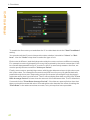
8.2 Flow Meter Settings
For the IC to collect data, or measure instant flow from the flow meter, the flow meter must
be enabled from the "Settings->Other" section.
40
IC-W1 User Manual
8 Flow Meter
8 Flow Meter
IC-W1 User Manual
To enable the flow meter port and allow the IC to collect data check the "Use Flow Meter"
setting.
You can also tell the IC how to interpret the data, whether it should be "Liters" or "Gallons". Use the "Units" drop down to select the type of unit.
Each meter is different, and the ticks produced by the meter can have a different meaning.
For example a meter might specify the every tick produced by the meter means that 1 Gallon of water has passed through it. In order for the IC to accurately measure the flow, we
need to specify this amount as the "Units per Pulse".
Finally, some meters, specially big meters, with big pipe diameters have a high volume per
tick / pulse value. For example some meters only tick once for every 10 gallons that have
passed through the meter. Depending on how much water is flowing through the pipes it
might take some time from tick to tick. The IC will not display flow data correctly if the "Flow
Rate Average Period" is lower than the amount of time between ticks. The IC defaults to
5 seconds for the "Flow Rate Average Period". If the ticks are spaced further than that
then you should increase this value. Increasing this value has also the effect of making the
"Flow Rate" in the status area less accurate, so try to keep it as low as possible..
41
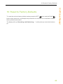
9 Cloud
The IrrigationCaddy Cloud Service is an Internet based system which allow users to communicate with their IrrigationCaddy devices on the go, anytime and anywhere. The user
can be at home, or all the way around the globe and still be able to access and control
his/her IrrigationCaddy unit.
For more information please go to:
https://cloud.irrigationcaddy.com/docs/User%20Manual/Default.htm
42
IC-W1 User Manual
9 Cloud
10 Reset to Factory Defaults
To reset the unit to its factory default values press the LEFT
button and the RIGHT
button at the same time, and keep them pressed for 4 seconds. The unit will then reset to
factory defaults and restart.
The display will say “Resetting and Rebooting…”, at this point you can let the buttons
go.
43
IC-W1 User Manual
10 Reset to Factory Defaults
11 Firmware Upgrade
IC-W1 User Manual
11 Firmware Upgrade
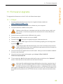
To upgrade the firmware on the IC-W1 unit follow these steps:
11.1 Steps:
1. Download the latest firmware from the IrrigationCaddy website at
http://irrigationcaddy.com.
2. Extract the contents of the ZIP file to a folder on your computer.
3. Copy the files into a USB memory stick.
Make sure the files are extracted onto the root of the memory stick; not
into a folder. If the files are placed into a folder the IC will not be able to
find them.
4. Insert the memory stick into the USB slot in the caddy.
5. Pull the power cable from the unit to turn it OFF
6. Press the OK
button and re-apply the power cable into the unit.
7. When you see the “Info” light next to the LCD blinking rapidly you can stop pressing the OK button.
Note that the light will first blink slowly, then when the files are found and
read it will blink very fast, then it will blink slowly again while the firmware is
being programmed into the unit.
8. Once the firmware is applied the unit will restart. Next you need to load the .bin file
from the user interface.
9. Once the unit is up and running again, go to http://<The IC-W1 IP
Address>/mpfsupload.
10. There select the .bin file that came with the firmware and click on the “Upload”
button. After that the unit should be on the latest firmware.
Note that if the blinking light keeps blinking for a long time (greater than 2
minutes), then the firmware will never load. This is probably due to either
the files not being on the USB memory stick, or not being at the root of the
stick. Also it is possible the memory stick file format is not in FAT format. Make sure
the USB memory stick is not in NTFS file format, or some other format other than
FAT.
44
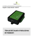
12 Troubleshooting
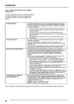
Issue
Possible Cause
"Configuration Error" is shown on the The WiFi security on the router the unit is trying to
browser after trying to connect to a
connect to is not compatible.
WiFi network (SSID)
The IC supports WEP40, WEP104, WPA, WPA2Personal, but it does not support WEP64, WPA2Enterprise or mix mode.
Fixes:
Change the WiFi security type on the router the
IC is trying to connect to.
The password entered is incorrect.
LCD Displays:
or
Another reason for this message is that the WiFi
security mode on the router is set to Mix-Mode
WPA+WPA2 for example.
Fixes:
Reset the unit (left + right arrow buttons for several
seconds), and try reconnecting using the correct
password.
LCD Displays:
Change the WiFi Security type to single mode, and
use WPA2-Personal for example.
The SSID the unit is trying to connect to is not available.
Fixes:
Make sure the SSID the unit is trying to connect is
and it never changes back to show the
available, and the signal strength is good.
IP address..
45
IC-W1 User Manual
12 Troubleshooting