1
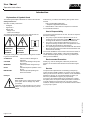
User Manual Operation Instructions 2.1EN-39001-E09 Hydraulic Operated Lubrication Pump HTL 101 Subject to modifications 6131b 03 810-55289-1 LINCOLN GmbH • Postfach 1263 • D-69183 Walldorf • Tel +49 (6227) 33-0 • Fax +49 (6227) 33-259 User Manual Operation Instructions 2.1EN-39001-E09 This User Manual was compiled on behalf of - the manufacturer - by Lincoln GmbH EdiDoc GmbH Heinrich-Hertz-Str. 2-8 Erzberger Str. 8 D-69169 Walldorf D-68753 Waghäusel All rights reserved. Any duplication of this User Manual, in its entirety or in part, by whatever means is prohibited without the prior consent in writing of Lincoln GmbH. Subject to modifications without prior notification. Subject to modifications © 2009 by Phone: +49 (6227) 33-0 Fax: +49 (6227) 33-259 E-Mail: [email protected] Page 2 of 28 LINCOLN GmbH • Postfach 1263 • D-69183 Walldorf • Tel +49 (6227) 33-0 • Fax +49 (6227) 33-259 User Manual Operation Instructions 2.1EN-39001-E09 Table of Contents Page Introduction Explanation of Symbols Used .............. ..................... ......... User´s Responsibility ..... ...................... ..................... ......... Environmental Protection .................... ..................... ......... Service ..... ..................... ...................... ..................... ......... 4 4 4 4 Safety Instructions Appropriate Use ............ ...................... ..................... ......... Misuse ...... ....... .............. ...................... ..................... ......... General Safety Instructions ................. ..................... ......... Accident Prevention Regulations ......... ..................... ......... Operation, Maintenance and Repair .... ..................... ......... Repairs .................... ...................... ..................... ......... Operation/Maintenance ................. ..................... ......... Disposal .... ..................... ...................... ..................... ......... Exclusion of Liability ...... ...................... ..................... ......... Installation ..................... ...................... ..................... ......... Installation and Maintenance of Hydraulic Hoses ........ 5 5 5 5 5 5 6 6 6 6 6 Description The Pump Model HTL 101 .................. ..................... ......... 7 Page Mai ntenance .............. ...................... ..................... .......... Lubricant Cartridge ..... ...................... ..................... .......... First insertion of cartridge ................. ..................... .......... Cartridge Replacement ..................... ..................... .......... Removal of Oil Strainer ..................... ..................... .......... Technical Data Ratings .. ........ .............. ...................... ..................... .......... Pressure Diagram: Ratio Comparison ................... .......... Dimensions ... .............. ...................... ..................... .......... Flow Rate Diagram ..... ...................... ..................... .......... Average output on medium-sized hydraulic hammers ...................... ..................... .......... Hydraulic Circuit .......... ...................... ..................... .......... 10 10 10 11 11 12 12 13 14 14 15 Troubleshooting ........ ...................... ..................... ........... 17 Components and Parts List Version H .................... ...................... ..................... .......... 18 Version N .................... ...................... ..................... .......... 20 Version P .................... ...................... ..................... .......... 22 Version R .................... ...................... ..................... ........... 24 Working Method .......... ...................... ..................... ......... 8 Adjustment and Operation Basic Adjustment of the Throttle Valve ..................... ......... Monitoring of Function ................... ..................... ......... Pump Element ............... ...................... ..................... ......... Pressure Relief Valve .... ...................... ..................... ......... Accessories Hydraulic Tubes .......... ...................... ..................... .......... 26 8 8 9 9 EC Declaration of i ncorporation .... ..................... .......... 27 Subject to modifications For further information refer to: Inst allation Instructions for kit of seals 542-34079-1 2.0-30008-B08 Inst allation Instructions for hose stud 2.0-39000-A08 Page 3 of 28 LINCOLN GmbH • Postfach 1263 • D-69183 Walldorf • Tel +49 (6227) 33-0 • Fax +49 (6227) 33-259 User Manual Operation Instructions 2.1EN-39001-E09 Introduction Explanation of Symbols Used The following description standards are used in this manual: Safety Instructions Structure of safety instructions: Pictogram Signal word Danger text - Danger note - How to avoid danger The following pictograms are used in this manual and are combined with the corresponding signal words: 101 3A94 4273a 00 - ATTENTION - CAUTION - ATTENTION - CAUTION - WARNING - WARNING 600 1a02 - NOTE - IMPORTANT The signal words give the seriousness of danger if the following text is not observed: ATTENTION CAUTION WARNING NOTE IMPORTANT refers to faults or damages on machines. refers to bad damages and possible injuries. refers to possible dangerous injuries. indicates improved operation of the device. indicates special operating features of the device. Example: ATTENTION! User's Responsibility To ensure the safe operation of the unit, the user is responsible for the following: 1. The pump / system shall be operated only for the intended use (see next chapter "Safety Instructions") and its design shall neither be modified nor transformed. 2. The pump / system shall be operated only if it is in a proper functioning condition and if it is operated in accordance with the maintenance requirements. 3. The operating personnel must be familiar with this Owner Manual and the safety instructions mentioned within and observe these carefully. The correct installation and connection of tubes and hoses, if not specified by Lincoln GmbH, is the user's responsibility. Lincoln GmbH will gladly assist you wit h any questions pertaining to the inst allation. Environmental Protection Waste (e.g. used oil, detergents, lubricants) must be disposed of in accordance with relevant environmental regulations. Service The personnel responsible for the handling of the pump / system must be suitably qualified. If required, Lincoln GmbH offers you full service in the form of advice, on-site installation assistance, training, etc. We will be pleased to inform you about our possibilities to support you purposef ully. In the event of inquiries pertaining to maintenance, repairs and spare parts, we require model specific data to enable us to clearly identify the components of your pump / system. Therefore, always indicate the part, model and series number of your pump / system. Subject to modifications 1 013A94 When making use of other than the tested spare parts, serious damage may affect your device. Therefore, for the operation of your device always use original parts made by Lincoln GmbH. Furthermore, you will find the following text symbols in this manual: Listing of applicable statements - Subpoint of applicable stat ements 1. Determination of the number or sequence of contents  Procedural instruction Page 4 of 28 LINCOLN GmbH • Postfach 1263 • D-69183 Walldorf • Tel +49 (6227) 33-0 • Fax +49 (6227) 33-259 User Manual Operation Instructions 2.1EN-39001-E09 Safety Instructions General Safety Instructions Appropriate Use The hydraulic operated lubrication pump model HTL 101 is designed for initial or for subsequent retrofit installation. It is designed for: 1. the automatic lubric ation of hydraulic hammers; 2. the automatic lubric ation of hydraulically driven units. The pump is able to deliver lubricants and chisel pastes up to NLGI - class 2. Misuse Any use of the hydraulic operated lubrication pump HTL 101 that is not expres sly mentioned in this user‘s manual will be regarded as misuse. If the hydraulic operated lubrication pump HTL 101 is used or operated in a different m anner other than specified, any c laim for warranty or liability will be null and void. NOTE 6001a 02 If personal injury or material damage occurs as a result of inappropriate operation, e.g. if the safety instructions are ignored or resulting from incorrect installation of the hydraulic operated lubrication pump HTL 101, no claim s or legal actions may be taken against Lincoln GmbH. Hydraulic operated lubrication pumps model HTL 101: - are designed with state-of-the-art technology. - can be assembled for safe operation. Incorrect use m ay res ult in bearing damage caus ed by under- or over-lubrication. Modifications or alterations to an installed system by the customer are subject to prior consultation with the manufacturer of the lubrication system or with its appointed dealers. Hydraulic operated lubrication pumps model HTL 101: - are not to be installed in the lower area of the hammer, - must be installed in such a way that the operator can always see the position of the low-level indicator of the follower piston. After each cartridge replacement be sure that the pump delivers lubricant. Accident Prevention Regulations To prevent accidents, observe all city, state or provincial and federal safety regulations of the country in which the hydraulic oper ated lubrication pump HTL 101 will be us ed. Operation, Maintenance and Repair ATTENTION! Before beginning with maintenance or repair work to the lubrication pump HTL 101, ensure that the hydraulic system of the carrier unit (the supply to the lubrication pump) is depressurized. 1013A94 ATTENTION! It is absolutely forbidden to carry out maintenance or repair work and to replace the cartridge while the hydraulic unit is in operation. 1013A94 Repairs Subject to modifications Repairs are only to be performed by authorized and qualified persons who are familiar with all applicable regulations. Page 5 of 28 LINCOLN GmbH • Postfach 1263 • D-69183 Walldorf • Tel +49 (6227) 33-0 • Fax +49 (6227) 33-259 User Manual Operation Instructions 2.1EN-39001-E09 Safety Instructions, continuation Operation, Maintenance and Repair, continuation Installation Operation / Maintenance Hydraulic operated lubrication pumps HTL 101 shall be operated only with an installed pressure relief valve shall regularly be supplied with clean lubricant cartridges operate automatically. However, check at regular intervals (approx. every 2 days) whether the pump effectively delivers lubricant ( visual check) Disposal Dispose of used or contaminated lubricants as well as of parts that were in touch with lubricant (e.g. em ptied cartridges) acc ording to the legal regulations pertaining to environmental protection. 1013A94 ATTENTION! Before installing or disassembling the lubrication pump HTL 101, ensure that the hydraulic system of the carrier unit (the supply to the lubrication pump) is depressurized. It is forbidden to manipulate the protection devices installed on the hydraulic unit. If necessary, these devices may be removed temporarily during the installation of the pump. The devices must be properly put back in place after installation. Us e only original spare parts or spare parts and cartridges authorized by Lincoln (see spare parts list, page 18 ff). IMPORTANT Exclusion of Liability The manufacturer of the lubrication pump HTL 101 does not accept any liability for damages caused by: tardy replacement of the cartridges (lack of lubricant) contaminated lubricants use of lubricants that are inappropriate or only c onditionally appropriate for the unit or which are not pum pable inappropriate disposal of used or contam inated lubricants arbitrary modification of system parts use of unauthorized spare parts and lubricant cartridges, including the usage of refilled cartridges with non- approved or contaminated lubricants 6001a 02 Observe the installation guidelines and instructions of the machine/unit manufacturer when drilling and welding, as well as the specified minimum distance on vehicle/chassis frames for holes between upper/lower rim of the frame or between two bore holes. Installation and Maintenance of Hydraulic Hoses 1013A94 ATTENTION! The operational safety of the lubrication pump HTL 101 is only guaranteed with a profess ional installation and maintenanc e of hydraulic hoses/lines. The following points must be observed! Hy draulic Hose/lines Subject to modifications may never be subjected to torsion must be installed twist-free must not rub against metal components or edges are to undergo regular visual checks and exchanged in the case of wear (or at the latest, 2 years after installation) Pay attention with non linear installations to allow for as large a bending radius as possible. K inks are to be avoided. In constricted installation conditions use pipe elbow unions to av oid the danger of kinking behind the hose socket. Page 6 of 28 LINCOLN GmbH • Postfach 1263 • D-69183 Walldorf • Tel +49 (6227) 33-0 • Fax +49 (6227) 33-259 User Manual Operation Instructions 2.1EN-39001-E09 Description The Pump Model HTL 101 is a hydraulically driven grease pump for the lubrication of hydraulic hamm ers or other units with an available hydraulic circuit. is compact and can therefore be fitted directly to the hammer or other units . Together with the carrier it forms a complete assem bly. is driven by the hydraulic system of the carrier . continuously delivers lubricant to the lubrication point while the hydraulic unit is in operation and stops when the hydraulic flow stops. The lubricant quantity is adjustable via the regulating throttle valve (see Fig. 3). is equipped with a visual lubricant level indicator by means of the follower plate of the cartridge. If the follower plate is located in the low-level position of the c artridge 10, the cartridge must be replaced. is protected by means of a 120 bar pressure relief valve 7 (cartridge). is equipped with an easy-to exchange pum p elem ent 5. is equipped with a lubrication hydraulic fitting 4 for manual lubrication override (e.g. if the hydraulic system fails to operate). does not require supplementary directional valve. has three different outlets 3 & 7 for the individual grease supply c onnection of the ham mer (unit). 613 2b03 Fig. 1 - Follower piston, cartridge full - Cartridge - Lubricant outlet, G ¼ - Lubrication hydraulic fitting, fo r manual lubrication (M = 14 Nm ±5%) 5 - Pump element 6 - Housing 7 - Pressure relief valve 120 bar (M = 12 Nm ±5%) 8 - Housing cover 9 - Eccentric (cam )shaft 10 - Low-level position (window) of the follower piston, cartridge empty 11 - Fastening holes for M 16 bolts 12 - Cover cap for the regulating throttle valve 13 - Oil return connection R (M = 30 Nm ± 5%) 14 - Oil pressure connection P (M = 30 Nm ±5%) 6001a02 NOTE If the lower lubricant outlet connection is used 7, the outlet fitting and the pressure relief v alve must be exchanged. If the rear outlet is used, the outlet fitting and closure plug must be exchanged. Subject to modifications 1 2 3 4 Components of the Lubrication Pump HTL -101 Page 7 of 28 LINCOLN GmbH • Postfach 1263 • D-69183 Walldorf • Tel +49 (6227) 33-0 • Fax +49 (6227) 33-259 User Manual Operation Instructions 2.1EN-39001-E09 Working Method  Connect the lubrication pump HTL 101 to the hydraulic system of the carrier by means of suitable hydraulic lines and connectors. The f low of hydraulic oil f rom the carrier is restricted (throttled) and flows: - via the pressure connection 14, (P, fig. 2) - through the filter which is installed below t he pressure connection - to the integrated hydraulically operated stepper motor - and back t o the hydraulic system of the carrier via the return line connection 13, R A driving pin attached to the stepper motor activates the eccentric shaft 9 (fig. 1) via a one-way clutch. The pump element is thereby actuated and delivers lubricant. The flow quantity of the hydraulic oil can be adjusted via the regulating throttle valve 12 (fig. 2), thereby, adjusting the output quantity of the pump accordingly. The throttle valve is notched, whereby 16 notches correspond t o one complete rotation. 6133b 03 Fig. 2 12 - Cover cap for throttle valve (fine restrictor) 13 - Return connection R, M 16 x 1.5 14 - Pressure connection P, M 16 x 1.5 with integrated oil s trainer Hydraulic oi l connection of the pump HTL 101 Adjustment and Operation Basic Adjustment of the Throttle Valve NOTE The eccentric shaf t is factory-set to 4 rpm (output 1 cm3/min). 60 01a02  Adjust the required amount of lubricant by means of the output diagram (fig. 13 & chapter “Adjustment of output“). - turning clockwise = less lubricant - turning anticlockwise = more lubricant WARNING! Risk of injury!! When adjusting the fine restrictor make sure to swit ch off the hydraulic drive! 1013 A94 600 1a02 60 11c07 Fig. 3 T hrottle valve adjustment The throttle valve may still be pressurized for a long time after switching off the hydraulic unit. Therefore, first of all, check whether the pressure connection P (14, fig. 2) is depressurized. The eccentric shaf t must not rotate anymore (see fig. 4)! Page 8 of 28 LINCOLN GmbH • Postfach 1263 • D-69183 Walldorf • Tel +49 (6227) 33-0 • Fax +49 (6227) 33-259 Subject to modifications IMPORTANT User Manual Operation Instructions 2.1EN-39001-E09 Adjustment and Operation, continuation Monitoring of Function The eccentric shaft 9 (Fig. 4), located at the bottom of the pump housing cover, ser ves for check ing the function. If it turns clockwise, the pum p elem ent is operating correctly. NOTE 6001a02 Before switching on the hydraulic unit, check whether there is sufficient lubricant in the cartridge. If necessary, replace the cartridge (see chapter „Maintenance“, page 10). IMPORTANT The lubrication pump must be protected with a pressure relief valve 7. NOTE If the lower outlet connection is used for lubricant delivery, the pres sure relief valve must be fitted to the upper outlet c onnection. 6134b03 Fig. 4 7 - Pressure relief valve 9 - Eccentric shaft Monitoring of Fu nction Pump Element During the operation the piston 4 (Fig. 5) sucks in lubricant from the cartridge via the suction bore hole 2 and delivers it to the c onnected lubrication point through the bore hole 1. An integrated c heck valve prevents the lubricant from returning to the cartridge. Piston diam eter, C7: ........................................................ 7mm Lubr icant output: .................................approx. 0.22 c m³/stroke 4349a02 Fig. 5 1 2 3 4 - Delivery bore hole - Suction bore hole - Return spring - Piston Pump Element Pressure Relief Valve The pressure relief valve limits the pressure build-up in the system, opens when a pressure of 120 bar is reac hed. NOTE If lubricant is expelled at the pressure relief v alve, this indicates that there is a blockage to, or at the lubrication point. Subject to modifications 6001a02 4195a99 Fig. 6 Pressure relief valve (cartridge) Page 9 of 28 LINCOLN GmbH • Postfach 1263 • D-69183 Walldorf • Tel +49 (6227) 33-0 • Fax +49 (6227) 33-259 User Manual Operation Instructions 2.1EN-39001-E09 Maintenance ATTENTION! ATTENTION ! Do not perform any maintenance or repair work or replace the cartridge while the hydraulic unit is in operation. Before beginning with maintenance or repair work on the lubrication pump HTL 101 and before dismantling it, ensure that the hydraulic system of the carrier is depressurized. 1013A94 1013A94 Lubricant Cartridge Capacity........................................................................... 400g Lubricant … ...………………………………..up to NLGI class 2 1) Chisel paste .......................................................642-37608-1 1) EP2 grease ........................................................642-37609-2 1) NOTE The cartridges are not available as single units. They are only supplied in packages of 12 cartridges. 6001a02 Dispose of emptied cartridges according to the legal regulations pertaining to environmental protection. 6007b03 Fig. 7 1 - Closure cap 2 - Cartridg e 3 - Follower plate Cartridge with Lubricant First insertion of cartridge  Lightly grease the inner o-r ing  Remove the closure cap (1, Fig. 7) from the cartridge  Insert the cartridge in the bore hole by lightly pressing and screw it into the housing (presented as in Fig. 8) handtightly  Vent housing:: - Remove closure plug (15) - Press red follower piston (3, Fig. 7) into the cartridge until lubricant comes out of the open bore hole - Close housing with closure plug, again  Operate the pump by switching on the hydraulic unit until lubricant flows out of the opened outlet (3) NOTE The pump delivers lubricant very slowly. It may take a while before the lubricant flows out of the outlet without air bubbles. 6135b07 Fig. 8 Insert cartridge into the lubrication pump HTL 101 3 - Lubricant outlet, G ¼ 7 - Pressure relief valve 120 bar (M = 12 Nm ±5%) 15 - Closure plug  Connect the supply hose to the lubrication point to one of the pump outlets (3) & (7). Thread: G 1/4“  Fill the lubricant supply hos e to the lubrication point via the lubrication hydraulic fitting by means of a m anually operated grease gun until the lubricant flows out at the lubrication point Page 10 of 28 LINCOLN GmbH • Postfach 1263 • D-69183 Walldorf • Tel +49 (6227) 33-0 • Fax +49 (6227) 33-259 Subject to modifications 6001a02 User Manual Operation Instructions 2.1EN-39001-E09 Maintenance, continuation Cartridge Replacement     Switch off the hydraulic unit Unscrew the old c artridge Remove the closure cap of the new cartridge Screw in the new cartridge hand-tightly in the housing - The pump is ready for operation again NOTE If afterwards the pump does not dispense lubricant immediately, vent the housing (see paragraph "vent housing", fig. 8). 6001a02 6136b03 Fig. 9 Cartridge Replacement Removal of Oil Strainer The oil strainer should be cleaned every 2000 operating hours. To do this, proceed as follows:  Depressurize hose lines of the hydraulic system on the carrier device.  Remove the pressure line to the lubrication pump HTL 101.  Unscrew the oil strainer and clean it. 6 137b03 Fig. 10 Cleaning the Oil Strainer Subject to modifications 16 - Oil strainer Page 11 of 28 LINCOLN GmbH • Postfach 1263 • D-69183 Walldorf • Tel +49 (6227) 33-0 • Fax +49 (6227) 33-259 User Manual Operation Instructions 2.1EN-39001-E09 Technical Data Ratings Lubrication Pump HTL 101 Lubrication output:........................................... 0.22 cm³/stroke Max. operating pressure (lubricant) - Hydraulic hammer ..................................................... 120 bar - with metering device.................................................. 270 bar Admissible operating temperature 1) ................... -25°C to 80°C Ratio .............................................................................1 : 1.65 Factory Output Settings Speed (rev olutions): ....................................................... 4 rpm max. Hydraulic pressure:............................................. 250 bar min. Hydraulic pressure:................................................ 40 bar Standard Fitting Connections Oil - Pressure (P) ............................................. M 16 x 1.5 m m Oil - Return (R)................................................. M 16 x 1.5 m m Lubricant outlet .............................................................. G 1/4“ 1) NOTE The minimum operating temperature depends on the pumpability of the lubricants. For Lincoln chisel pastes, it is -25°C. Observ e the manufacturer‘s specifications for 600 1a02 standard greases. Pressure Diagram: Ratio Comparison The following pres sure diagram depicts the relationship between the inlet press ure of the hydraulic system and the maximum outlet pressure of the lubrication pump with closed outlet or with a blockage. The maximum outlet pressure was determ ined with an EP 2 grease at room tem perature. 4440a02 Fig. 11 Pressure diagram Subject to modifications A - Oil pressure: Hydraulic System (Inlet) B - Delivery Pressure: Lubricant Outlet Page 12 of 28 LINCOLN GmbH • Postfach 1263 • D-69183 Walldorf • Tel +49 (6227) 33-0 • Fax +49 (6227) 33-259 User Manual Operation Instructions 2.1EN-39001-E09 Technical Data, continuation Dimensions B-HTL101-050a08 un d 6138b03 Dimensio ns of the Hydraulic Lubrication Pump HTL 101 (all dimensions in mm) Subject to modifications Fig. 12 Page 13 of 28 LINCOLN GmbH • Postfach 1263 • D-69183 Walldorf • Tel +49 (6227) 33-0 • Fax +49 (6227) 33-259 User Manual Operation Instructions 2.1EN-39001-E09 Technical Data, continuation Flow Rate Diagram IMPORTANT WARNING! Risk of injury! Before adjust ing the f ine restrictor make sure to switch off the hydraulic drive! 6 001a0 2 1 013A94 The throttle valve may still be pressurized for a long time after switching off the hydraulic unit. Therefore, first of all, check whether the pressure connection P (14, fig. 2) is depressurized. The eccentric shaft must not rotate anymore (see fig. 4)! Lubricant Output of the HTL 101 (at 100 bar back-pressure and 60 to 80 °C operating temperature) Output cm³/min Speed of the eccentric shaft rpm (see version P, pos. 13, pages 22 and 23) B- HT L101-040a09 – close < < < Throttling (by means of notches) > > > open + 6 011d0 7 Fig. 13 Flow rate diagram Average output on medium-sized hydraulic hammers Max. speed of the eccentric shaft ............. .................. 20 rpm Max. output .... ..................... ...................... ........... 4.4 cm³/min Not ches per throttle revolution .................. ...................... .... 16 Factory-setting: Position of the throttle valve (fig. 13) ........ ............ 20 notches Speed of eccentric shaft ..... ...................... ........ approx. 4 rpm Output ............ ..................... ...................... . approx. 1 cm³/min The integrated pump element supplies 0.22 cm³ of lubricant per stroke. It is driven by the eccentric shaft (1 stroke / revolution). The speed of the eccentric shaft is determined by the position of the throttle valve. The t hrottle valve is notched, whereby 16 notches correspond to one complete rotation. Adjusting the output:  Open the cover cap of the throttle valve 12 (fig. 2)  Close the throttle by turning it clockwise.  Determine the number of notches corresponding to the required output by means of the out put diagram (fig. 13).  Example: 3 - required output …..… ……………..…………… 2 cm /min - notches ……..…………… ………………..….. approx. 42 - speed of eccentric shaft …………..…… approx. 9 rpm  Open the throttle counterclockwise until you have reached the number of notches.  Check the output. If necessary, adapt the output proceeding from this throttle position: - turning clockwise …………………………... less lubricant - turning anticlockwise …………………… … more lubricant Page 14 of 28 LINCOLN GmbH • Postfach 1263 • D-69183 Walldorf • Tel +49 (6227) 33-0 • Fax +49 (6227) 33-259 Subject to modifications From output diagram fig. 13 the adjustment of the throttle valve can be determined in dependency of the lubricant output. User Manual Operation Instructions 2.1EN-39001-E09 Technical Data, continuation Hydraulic Circuit 4442a05 Fig. 14 Hydraulic Circuit HTL 101 2 - Filter 3 - Stepper m otor 4 - Throttle, adjustable 5 - By-pass for warming up Subject to modifications 1 - Screen Page 15 of 28 LINCOLN GmbH • Postfach 1263 • D-69183 Walldorf • Tel +49 (6227) 33-0 • Fax +49 (6227) 33-259 User Manual Operation Instructions 2.1EN-39001-E09 Subject to modifications Note: Page 16 of 28 LINCOLN GmbH • Postfach 1263 • D-69183 Walldorf • Tel +49 (6227) 33-0 • Fax +49 (6227) 33-259 User Manual Operation Instructions 2.1EN-39001-E09 Troubleshooting Fault: Pump does not deliver the lubricant Cause: Remedy: Cartridge empty  Replace the cartridge, see page 11. Lubricant supply blocked  Check the cartridge. No oil pressure supply  Check the hydr aulic system and repair it.  Check the tube and hose lines and replace them. Air entrapments in the suction area of the cartrigde  Vent housing, s ee page 10 „First Instertion of cartridge“. Fault: Lubricant quantity too low Cause: Remedy:  Turn the throttle anticlockwise by 1 to 2 notches (more lubricant will flow out), see Fig. 3. Throttle not adjusted correctly Fault: Lubricant quantity too high Cause: Remedy:  Turn the throttle clockwise by 1 to 2 notches (less lubricant will flow out), see Fig. 3. Throttle not adjusted correctly Fault: Lubricant leaking at the cartridge inlet Cause: Remedy:  Check the sealing ring in the pump unit and replace it if necessary.  Check wether the cartridge is threaded correctly (hand-tight seat). Leakage Fault: Lubricant leaking at the grease outlet Cause: Remedy:  Check the fittings and retighten them if necessary. Leakage Fault: Oil pressure leaking at the hydraulic system Cause: Remedy:  Check the fittings and retighten them if necessary. Leakage Troubleshooting Subject to modifications Tab. 1 Page 17 of 28 LINCOLN GmbH • Postfach 1263 • D-69183 Walldorf • Tel +49 (6227) 33-0 • Fax +49 (6227) 33-259 User Manual Operation Instructions 2.1EN-39001-E09 Components and Parts List 4439c05 Fig. 15 Exploded drawing, model H (see identification plate) Page 18 of 28 LINCOLN GmbH • Postfach 1263 • D-69183 Walldorf • Tel +49 (6227) 33-0 • Fax +49 (6227) 33-259 Subject to modifications Exploded drawing, model H User Manual Operation Instructions 2.1EN-39001-E09 Components and Parts List, continuation Parts List, model H Item 1 Description Cartridge with chisel paste, 400 g Connection fitting XGE 6 - SG ¼ AC Qty. Part-Number Item Description 2) 12 642-37608-1 9 1 223-10055-5 10 Kit of seals 1 542-34079-1 11 Pump elem ent C 7 1 642-29086-1 4.1 O-ring 19.2 x 3 1 219-13053-6 4.2 O-ring 14.2 x 2.5 2 219-13053-5 5 Hydraulic fitting 1 251-14109-6 6 Closure plug G ¼ 3 223-13702-1 7 Valve body, 120 bar 1 235-14343-5 8 Housing cover, assy. 1 542-34079-4 8.1 Hex. head screw, M6 x 18 C 4 201-13668-1 8.2 Shim St A 6.4 C 4 209-13011-5 8.3 Package ring 12 x 30 x 7 1 220-12229-8 8.4 Bearing 1 250-14064-6 8.5 Sealing ring 122.7 x 2.5 1 442-70146-1 2 3 1) 4 12 13 1) Pump housing, assy. 1 642-40950-1 Filter, assy. 1 528-32215-1 1 1 304-19893-1 219-12451-3 1 223-10055-4 1 542-34079-2 Oil inlet fitting M16 x 1.5 x M20 x 1.5 A, 8 S O-ring Oil outlet fitting XGE 85 G¼ A A3C Throttle valve, assy. see IMPORTANT note: IMPORTANT Please use Loctite 403 to glue in flat packing (item 3). 6001a 02 2) see NOTE: NOTE 6001a 02 The marked parts are glued into the housing for reasons of vibration. If dismantled they may be destroyed. If so, replace pump (item 9) completely. Parts list, model H (see identification plate) Subject to modifications Tab. 2 Qty. Part-Number Page 19 of 28 LINCOLN GmbH • Postfach 1263 • D-69183 Walldorf • Tel +49 (6227) 33-0 • Fax +49 (6227) 33-259 User Manual Operation Instructions 2.1EN-39001-E09 Components and Parts List, continuation 4439e08 Fig. 16 Exploded drawing, model N (see identification plate) Page 20 of 28 LINCOLN GmbH • Postfach 1263 • D-69183 Walldorf • Tel +49 (6227) 33-0 • Fax +49 (6227) 33-259 Subject to modifications Exploded drawing, model N User Manual Operation Instructions 2.1EN-39001-E09 Components and Parts List, continuation Parts List, model N Item 1 Description Cartridge with chisel paste, 400 g Connection fitting XGE 6 - SG ¼ AC Qty. Part-Number Item Description 2) 12 642-37608-1 9 1 223-10055-5 10 Kit of seals 1 542-34079-1 11 Pump elem ent C 7 1 642-29086-1 4.1 O-ring 19.2 x 3 1 219-13053-6 4.2 O-ring 14.2 x 2.5 2 219-13053-5 5 Hydraulic fitting 1 251-14109-6 6 Closure plug G ¼ 3 223-13702-1 7 Valve body, 120 bar 1 235-14343-5 8 Housing cover, assy. 1 542-34079-4 8.1 Hex. head screw, M6 x 18 C 4 201-13668-1 8.2 Shim St A 6.4 C 4 209-13011-5 8.3 Package ring 12 x 30 x 7 1 220-12229-8 8.4 Bearing 1 250-14064-6 8.5 Sealing ring 122.7 x 2.5 1 442-70146-1 2 3 1) 4 12 13 1) Pump housing, assy. 1 642-40950-1 Filter, assy. 1 528-32215-1 1 1 304-19893-1 219-12451-3 1 223-10055-4 1 542-34079-9 Oil inlet fitting M16 x 1.5 x M20 x 1.5 A, 8 S O-ring Oil outlet fitting XGE 85 G¼ A A3C Throttle valve, assy. see IMPORTANT note: IMPORTANT Please use Loctite 403 to glue in flat packing (item 3). 6001a 02 2) see NOTE: NOTE 6001a 02 The marked parts are glued into the housing for reasons of vibration. If dismantled they may be destroyed. If so, replace pump (item 9) completely. Parts list, model N (see identification plate) Subject to modifications Tab. 3 Qty. Part-Number Page 21 of 28 LINCOLN GmbH • Postfach 1263 • D-69183 Walldorf • Tel +49 (6227) 33-0 • Fax +49 (6227) 33-259 User Manual Operation Instructions Components and Parts List, continuation 2.1EN-39001-E09 4439e05 Fig. 17 Exploded drawing, model P (see identification plate) Page 22 of 28 LINCOLN GmbH • Postfach 1263 • D-69183 Walldorf • Tel +49 (6227) 33-0 • Fax +49 (6227) 33-259 Subject to modifications Exploded drawing, model P User Manual Operation Instructions 2.1EN-39001-E09 Components and Parts List, continuation Parts List, model P Item 1 Description Cartridge with chisel paste, 400 g Connection fitting XGE 6 - SG ¼ AC Qty. Part-Number Item Description 2) 12 642-37608-1 9 1 223-10055-5 10 Kit of seals 1 542-34079-1 11 Pump elem ent C 7 1 642-29086-1 4.1 O-ring 19.2 x 3 1 219-13053-6 4.2 O-ring 14.2 x 2.5 2 219-13053-5 5 Hydraulic fitting 1 251-14109-6 6 Closure plug G ¼ 3 223-13702-1 7 Valve body, 120 bar 1 235-14343-5 8 Housing cover, assy. 1 542-34079-4 8.1 Hex. head screw, M6 x 18 C 4 201-13668-1 8.2 Shim St A 6.4 C 4 209-13011-5 8.3 Package ring 12 x 30 x 7 1 220-12229-8 8.4 Bearing 1 250-14064-6 9.5 Sealing ring 122.7 x 2.5 1 442-70146-1 2 3 1) 4 12 13 1) Pump housing, assy. 1 642-40950-1 Filter, assy. 1 528-32215-1 1 1 304-19893-1 219-12451-3 1 223-10055-4 1 542-34281-1 Oil inlet fitting M16 x 1.5 x M20 x 1.5 A, 8 S O-ring Oil outlet fitting XGE 85 G¼ A A3C Throttle valve, assy. see IMPORTANT note: IMPORTANT Please use Loctite 403 to glue in flat packing (item 3). 6001a 02 2) see NOTE: NOTE 6001a 02 The marked parts are glued into the housing for reasons of vibration. If dismantled they may be destroyed. If so, replace pump (item 9) completely. Parts list, model P (see identification plate) Subject to modifications Tab. 4 Qty. Part-Number Page 23 of 28 LINCOLN GmbH • Postfach 1263 • D-69183 Walldorf • Tel +49 (6227) 33-0 • Fax +49 (6227) 33-259 User Manual Operation Instructions 2.1EN-39001-E09 Components and Parts List, continuation 4439g07 Fig. 18 Exploded drawing, model R (see identifica tion plate) Page 24 of 28 LINCOLN GmbH • Postfach 1263 • D-69183 Walldorf • Tel +49 (6227) 33-0 • Fax +49 (6227) 33-259 Subject to modifications Exploded drawing, model R User Manual Operation Instructions 2.1EN-39001-E09 Components and Parts List, continuation Parts List, model R Item 1 2 3 1) 4 Description Cartridge with chisel paste, 400 g Connection fitting XGE 6- SG ¼ AC Qty. Part-Num ber Item 12 642-37608-1 9 1 223-10055-5 Kit of seals 1 Pump element C7 1 Qty. Part-Number Pum p, ass y. 1 642-40950-1 9.0 Stepper motor, SSVV6-K, assy. 1 619-29090-1 542-34079-1 9.1 O-ring 5,0x1,5 2 219-12222-2 642-29086-1 9.2 Heavy duty dowel SG 5,0x16 4 215-10560-3 2 211-10213-2 2 201-10431-6 2 211-10213-1 9.3 Safety was her 5,4 C, self-locking Screw, hex-socket 10.9 M5x40 C Safety was her 6,5 C, self-locking 4.1 O-ring 19,2x3 1 219-13053-6 4.2 O-ring 14,2x2,5 1 219-13053-5 5 Hy draulic fitting 1 251-14109-6 9.5 6 Closure plug G ¼ 3 223-13702-1 9.6 Screw 10.9 M6x50 A3C 2 200-10078-3 7 Valve body, 120 bar 1 235-14343-5 9.7 Spring DF50-3 DA 8x0,8xx28,8 2 218-10141-7 8 Housing cover, assy. 1 542-34079-4 9.8 Bracket, assy. with spring 1 542-34079-7 8.1 Screw, hex-socket M6x18 C 4 201-13668-1 9.9 Coupling nut M11x1x5,0 F 1 519-32307-1 8.2 Washer St. A 6,4 C 4 209-13011-5 10 Filter, assy. 1 528-32215-1 8.3 Package ring 12x30x7 1 220-12229-8 8.4 Bearing 1 250-14064-6 1 1 304-19893-1 219-12451-3 1 223-10055-4 8.5 Sealing ring 122,7x2,5 1 442-70146-1 1 542-34281-1 9.4 2) 11 12 13 Tab. 5 1) Description Thr ottle valve Parts list, model R (see identification plate) see IMPORTANT note: 2) see IMPORTANT note: IMPORTANT IMPORTANT Please use Loctite 403 to glue in flat packing ( item 3). Please use Loctite 274 to mount screw, hex-socket (item 9.4). 6001a02 Subject to modifications 6001a 02 Oil inlet fitting M16x1,5xM20x1,5 A, 8S O-ring Oil outlet fitting XGE 85 G ¼ A A3 C Page 25 of 28 LINCOLN GmbH • Postfach 1263 • D-69183 Walldorf • Tel +49 (6227) 33-0 • Fax +49 (6227) 33-259 User Manual Operation Instructions 2.1EN-39001-E09 Accessories Hydraulic tubes NOTE For applications of pump HTL 101 on hammers, use hoses with special fittings that resist the high vibrations during the hammer’s operation. Standard hose fittings are not suitable for this type of application as they would spoil within a short period of time. 6001a 02 Our accessories comprise special hoses (DN 6 Type 2040N-04V00 with black outside coating) in various lengths for the connection of pump HTL 101 (oil pressure and oil return) to the hydraulic system of a hammer. The connecting fittings are made of high-tensile special steel and are provided with fittings DKOS 8-S-M16 x 1.5 1 C9PX-8-04S. The following hoses can be ordered: Part no. Kind of connection, both sides Tube length in mm Material of tube 666-34169-1 DN 6 x 420 DKOS / DKOS 8 – S 420 HD DN 6 2040 N-04V00 666-34169-2 DN 6 x 430 DKOS / DKOS 8 – S 430 HD DN 6 2040 N-04V00 666-34169-3 DN 6 x 450 DKOS / DKOS 8 – S 450 HD DN 6 2040 N-04V00 666-34169-4 DN 6 x 470 DKOS / DKOS 8 – S 470 HD DN 6 2040 N-04V00 666-34169-5 DN 6 x 480 DKOS / DKOS 8 – S 480 HD DN 6 2040 N-04V00 666-34169-6 DN 6 x 490 DKOS / DKOS 8 – S 490 HD DN 6 2040 N-04V00 666-34169-7 DN 6 x 500 DKOS / DKOS 8 – S 500 HD DN 6 2040 N-04V00 666-34169-8 DN 6 x 540 DKOS / DKOS 8 – S 540 HD DN 6 2040 N-04V00 666-34169-9 DN 6 x 550 DKOS / DKOS 8 – S 550 HD DN 6 2040 N-04V00 666-34170-1 DN 6 x 560 DKOS / DKOS 8 – S 560 HD DN 6 2040 N-04V00 666-34170-2 DN 6 x 600 DKOS / DKOS 8 – S 600 HD DN 6 2040 N-04V00 666-34170-3 DN 6 x 610 DKOS / DKOS 8 – S 610 HD DN 6 2040 N-04V00 666-34170-4 DN 6 x 620 DKOS / DKOS 8 – S 620 HD DN 6 2040 N-04V00 666-34170-5 DN 6 x 650 DKOS / DKOS 8 – S 650 HD DN 6 2040 N-04V00 666-34170-6 DN 6 x 700 DKOS / DKOS 8 – S 700 HD DN 6 2040 N-04V00 666-34170-7 DN 6 x 750 DKOS / DKOS 8 – S 750 HD DN 6 2040 N-04V00 666-34170-8 DN 6 x 800 DKOS / DKOS 8 – S 800 HD DN 6 2040 N-04V00 666-34170-9 DN 6 x 850 DKOS / DKOS 8 – S 850 HD DN 6 2040 N-04V00 666-34171-1 DN 6 x 900 DKOS / DKOS 8 – S 900 HD DN 6 2040 N-04V00 666-34171-2 DN 6 x 950 DKOS / DKOS 8 – S 950 HD DN 6 2040 N-04V00 666-34171-3 DN 6 x 1000 DKOS / DKOS 8 – S 1000 HD DN 6 2040 N-04V00 666-34171-4 DN 6 x 1250 DKOS / DKOS 8 – S 1250 HD DN 6 2040 N-04V00 666-34171-5 DN 6 x 1500 DKOS / DKOS 8 – S 1500 HD DN 6 2040 N-04V00 Hydraulic tubes Subject to modifications Tab. 6 Page 26 of 28 LINCOLN GmbH • Postfach 1263 • D-69183 Walldorf • Tel +49 (6227) 33-0 • Fax +49 (6227) 33-259 User Manual Operation Instructions 2.1EN-39001-E09 Original Language D GB F E I EG- Einbauerklärung EC Declaration of incorporation Déclaration CE d'incorporation Declaración CE de incorporación Dichiarazione CE di incorporazione Hiermit erklären wir, dass die Bauart von Herewith we decl are that the model of Par la présente, nous déclarons que le produit ci-dessous Por la presente, declaramos que el modelo suministrado Si dichiara che il prodotto da noi fornito Hydraulic Operated Lubrication Pump HTL101 in der von uns gelieferten Ausführung zum Einbau in eine Maschine bestimmt ist und dass ihre Inbetriebnahme solange untersagt ist, bis festgestellt wurde, dass die Maschine, in die das o. g. Produkt eingebaut werden soll, den Bestimmungen aller einschlägigen grundlegenden Sicherheits- und Gesundheit sanforderungen entspricht, einschließlich deren zum Zeitpunkt der Erklärung gelt enden Änderungen. Der Hersteller verpflichtet sich, technische Dokumente (gem. Anhang VII Teil B) bei begründeter Anfrage zum o. g. Produkt einzelstaatlichen Stellen in gedruckter Form zur Verfügung zu stellen. in the supplied version is intended to be incorporated into machinery and must not be put into service until the machinery into whic h it is to be incorporated has been declared in conformity with the provisions of the rel evant fundamental requirements on health and safety, including all modifications of this directive valid at the time of the declaration. The manufacturer undertakes to make available any technical documents in printed version (following Annex VII Part B) to subnational authorities in the case of reasonable request regarding the above menti oned product. Angewendete harmonisierte Normen, insbesondere: Applied harmonized standards i n particular: Maschinenrich tlinie 2006/42/EG dans la version dans laquelle nous le livrons, est destiné à être installé sur une machine et que sa mise en service est interdite tant qu’il n’aura pas été constaté que la machine sur laquelle le produit mentionné ci-dessus doit être installé est conforme aux réglementations régissant toutes les exi gences fondamentales de sécurité et celles relati ves à la santé, y compris les amendements en vigueur au moment de la présente déclaration. Le fabricant s’engage, en cas de demande justifiée, à fournir sous forme écrite aux organismes nationaux respectifs les documents techniques (suivant Annexe VII, Partie B) relatifs au produit ci-dessus. Normes harmonisées, notamment : Machinery Directive 2006/42/EC DIN EN ISO 12100 – Teil 1 & 2 – Part 1 & 2 Directive machines 2006/42/CE – Parties 1 & 2 en la versión suministrada es desti nada a ser incorporada en una máquina y que su puesta en servicio está prohibida antes de que la máquina en la que vaya a ser incorporada haya sido declarada conforme a las disposiciones de los requisitos pertinentes y fundamentales de salud y seguridad en su redacción vigente en el momento de instal ación. El fabricante se obliga a hacer disponible documentos técnicos (según anexo VII parte B) en versión imprimida a entes uniestatales a petición fundada referente al producto arriba mencionado. nella versione da noi fornita è destinato all’installazione in una macchina e che la relativa messa in esercizio resta vietata fino all’avvenuto accertamento della conformità della macchina nella qual e il suddetto prodotto deve essere installato con tutti i requisiti basilari prescritti in termini di sicurezza e di salute, incluse le relative modifiche vigenti al momento della dichiarazione. Il costruttore si impegna a mettere a disposizione la documentazione tecnica (ai sensi dell’Allegato VII partel B) in forma scritta relativa al summenzionato prodotto dietro richiesta motivata presso le singole sedi nazionali. Normas armonizadas utilizadas, particularmente: Norme armonizzate applicate in particolare: Directiva de máquinas 2006/42/CE – Parte 1 & 2 Direttiva Macchine 2006/42/CE – Parte 1 e 2 Sicherheit von Maschinen Safety of machinery Sécurité de machines Seguridad de máquinas Sicurezza delle macchine Grundbegriffe, allgemeine Gestaltungsleitsätze Basic terms, general design guidelines Notions fondamentales, directives générales d’élaboration Términos básicos, axi omas generales de diseño Concetti basilari, principi guida generali Pumpen und Pumpengeräte für Flüssigkeiten Allgemeine sicherungstechnische Anforderungen Pumps and pump units for liquids DIN EN 908 Pompes et groupes de pompes pour liquides Exigences en matière de sécurité technique Bombas y equipos de bombas para líquidos Prescripciones general es referente a la seguridad Pompe e dispositivi di pompaggio per liquidi Requisiti generali di sicurezza tecnica General safety requirements Lincoln GmbH Heinrich-Hertz-Str. 2-8 D-69169 Walldorf Subject to modifications Walldorf, Nov 30, 2009, Dr.-Ing. Z. Paluncic Director Research & Development Page 27 of 28 LINCOLN GmbH • Postfach 1263 • D-69183 Walldorf • Tel +49 (6227) 33-0 • Fax +49 (6227) 33-259 User Manual Operation Instructions Lincoln’s Global Distribution and Service Network – The Best in Our Industry – Whatever service is required – selecting a lubricating system, customised system installation or the supply of top quality products – you will always be best advised by the staff of the Lincoln offices, representatives and contract dealers. Systems dealers Our systems dealers have the most ext ensive specialised knowledge in our industry. They plan your installations to suit your specifications with exactly the combination of Lincoln components that you need. They then build the installations at your operation with experienced technicians or work closely with your personnel to ensure that everything goes smoothly. All dealers have the complete range of pumps, distributers, monitoring devices and accessories in stock and meet our exacting demands with their specialised knowledge about products, installations and service. Whenever and wherever you need our experts, from St. Louis to Singapore, Walldorf and worldwide, Lincoln’s first-class systems dealers are at your service. Find out where the nearest Lincoln distribution and service off ice to you is located: America: Lincoln Industrial One Lincoln Way St. Louis, MO 63120-1578 USA Phone: (+1) 314 679 4200 Fax: (+1) 800 424 5359 Home: www.lincolnindustrial.com Europe/Africa/Asia: Lincoln GmbH Tel: (+49) 6227 33-0 Fax: (+49) 6227 33-259 E-Mail: [email protected] Asia/Australia/Pacific: Lincoln Industrial 3 Tampines Central 1 Corporation # 04-05 Abacus Plaza Singapore 529540 Heinrich-Hertz Straße 2-8 69190 Walldorf Germany © Copyright 2009 Printed in Germany Phone: (+65) 6588-0188 Fax: (+65) 6588-3438 E-Mail: [email protected] DI N EN I SO 9 001 durch DQS R eg.-Nr. 799 DIN EN ISO 14 001 du rch G UT