1
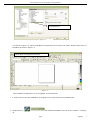
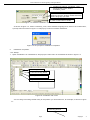
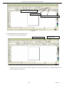
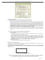
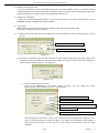
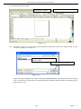
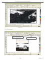
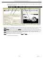
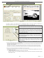
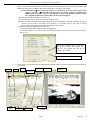
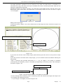
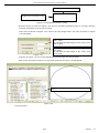
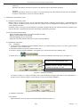
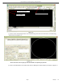
User’s Manual of Laser Engraving Cutting Software
User’s Manual of RD Laser Engraving Cutting Software
There are two kinds of RD laser engraving cutting software. One is based on the direct output software of CorelDraw
(hereinafter referred to as CorelDraw Laser); the other is based on the direct output software of AutoCAD (hereinafter
referred to as AutoCAD Laser). Now we are going to introduce them in turn:
I.
Introduction of CorelDraw_Laser
1.1 Features of CorelDraw_Laser
Mainly used in movement control, it is an important part of laser movement control and is. It realizes effective
control to laser numerical control machine tool by computer and accomplishes processing tasks according to
user’s different requests. There are its functions and features below:
1.CorelDraw_Laser is a plug-in module stalled in CorelDraw, utilizing indirectly powerful functions of plotting and
edit such as zooming and circumrotating.
2.It supports almost all the file formats supported by CorelDraw, including vector formats (such as Plt and AI) and
bitmap formats (such as BMP).
3.It is able to support the file formats of DST and DSB (not supported by CorelDraw itself) by the import function
of CorelDraw_Laser module itself.
4.It supports the function of files synthesizing by utilizing the import function of CorelDraw, allowing many files to
be exported and processed once and for all.
1.2 Environmental requirements
1.Above CPU586, above PIII or PV recommended
2.Memory, above 256M recommended
3.Windows2000/XP, XP recommended
4.Support the software of CoreDraw11 and CorelDraw12.
1.3 Installation and startup
1.3.1 Installation
1. You should have installed CoreDraw11 or CorelDraw12 before you install CorelDraw_Laser. If you don’t,
please install CoreDraw11 or CorelDraw12 on your computer first.
2. Open CoreDraw11 or CorelDraw12, complete the configuration before installation.
Figure 1-1
⑴ As shown in figure 1-1, enter the main menu of CorelDraw, choose CorelDraw menu, tools->options, a
menu As shown in figure 1-2 will pop up:
Page
29pages
1
User’s Manual of Laser Engraving Cutting Software
Select Visual Basic
for applications
Figure 1-2
⑵As shown in figure 1-2, select Visual Basic for applications, then click on Ok button. Now the main menu of
CorelDraw is shown in figure 1-3:
Visual Basic for applications tool bar
Figure 1-3
The CorelDraw configuration is now completed, close CorelDraw.
3. In order to ensure smooth installation, we suggest you to close the Anti-Virus Software first.
, the software installation menu as shown in figure 1-4 will pop
4. Double click on
up:
Page
29pages
2
User’s Manual of Laser Engraving Cutting Software
1. Includes two options: CorelDraw_Laser
and AutoCAD_Laser. Select
CorelDraw_Laser
2. Includes three options: Simplified Chinese,
Traditional Chinese, English. Please select the
software language you need.
3. Click on this button to install.
Figure 1-4 software installation menu
As shown in figure 1-4, select CorelDraw_Laser, select software language, then click on the Install button,
a prompt menu as shown in figure 1-5 will pop up to show successful installation.
Figure 1-5 the prompt for installation completion
5.
Installation completion.
1.3.2 Startup
1. Open CorelDraw11 or CorelDraw12, will pop up the main menu of CorelDraw as shown in figure 1-6:
LaserUsing
tool bar
Laser Processing button
Settings button
Import DST/DSB data button
Figure1-6 CorelDraw main menu
You can drag LaserUsing toolbar freely to the position you accustomed to, for example, as shown in figure
1-7:
LaserUsing tool bar
Page
29pages
3
User’s Manual of Laser Engraving Cutting Software
Laser Processing button
Settings
button
Import DST/DSB data button
Figure1-7
1.4 Operation instruction of CorelDraw_Laser
1.4.1 Settings of the settings dialog box
LaserUsing tool bar
Settings button
Figure1-8
As shown in figure 1-8, click on the button Settings in the LaserUsing toolbar, the Settings dialog box as
shown in figure 1-9 will pop up:
Page
29pages
4
User’s Manual of Laser Engraving Cutting Software
Figure1-9 Settings
dialog box
1. Selection of file format
(1) Settings of CorelDraw_Laser (CorelDraw direct output software)
Supporting two formats, PLT-HPGL Plotter and AI-Adobe Illustrator
a. Generally, we should select “AI-Adobe Illustrator” and set the “Curve Precision” between 80 and
100. The higher the precision is, the smoother the curve is, and the relevant cutting speed is faster.
Note: If the precision is set too high, it may lead to the phenomena that the laser head is
dithering when processing, in this case, we should adjust the precision value lower
accordingly. If it is set too low, the exported curve may be unsmooth (or even turned into a
straight line), in this case, we should adjust it higher accordingly.
b. Select “AI-Adobe Illustrator”, if you find the graph is abnormal during the output processing (for
example, there is one more line segment when outputting the graph), you can select “PLT-HPGL
Plotter”.)
(2) settings of AutoCAD_Laser (AutoCAD direct output software)
It only supports the file format of “DXF-AutoCAD File”.
a. Curve precision
It is generally set between 80 and100. The higher the precision value is, the smoother the
curve is, and the relevant cutting speed is faster.
Note: If the precision is set too high, it may lead to the phenomena that the laser head is
dithering when processing, in this case, we should adjust the precision value lower
accordingly. If it is set too low, the exported curve may be unsmooth (even turn to a
straight line), in this case, we should adjust it higher accordingly.
b. Whether to Output text
If you need to output text, select it, if not, don’t select it.
2. Whether to Delete repeated track.
If this feature is selected, the software will delete repeated tracks automatically. It will only cut once for
outputting and for several times for the contrary.
For example, draw two overlapped rectangle in CorelDraw (as shown in figure 1-10), if you select Delete
repeated track, the rectangle will only be cut once when output cutting. If you don’t select it, the rectangle
will be cut twice.
A (a)
D (d)
B (b)
C (c)
Figure 1-10. Two overlapped rectangles
Note: if you select Delete repeated track, it will influence the speed for opening the software.
So normally, we don’t select it (especially for figures with too much data).
Page
29pages
5
User’s Manual of Laser Engraving Cutting Software
3. Selection of the Speed unit
It is very convenient for users to set the speed when using the software. Users can select the speed
units of meter/minute or millimeter/second according to their own habits. All the speed values used in the
software interface to be set by users should adopt the selected unit.
4. Selection of Language.
Users can select the language shown in the menu according to their own requirements, such as
Simplified Chinese, Traditional Chinese or English.
5. Code setup
Manufacturers use this function to set manufacture code and users’ time limit code.
The steps of setting code are as follows:
6. (1) Click on the Code setup button, the dialog box Input manufacturer code as shown in figure 1-11 will
pop up:
1. Input 6 bit manufacturer code
2. Select USB port
Figure1-11
(2) Connect the computer with the laser machine with the USB interface, then input the correct code
authorized by the manufacturer and select right USB port, click on the Ok button, the dialog box
Code setup as shown in figure 1-12 will pop up:
Figure 1-12
a)
Setup of the Manufacturer Code
Click on the Manufacture code button shown in figure 1-12, the dialog box Setup
Manufacturer Code as shown in figure 1-13 will pop up:
1. Input the old manufacturer code
2. Input the new manufacturer code
3. Repeat the new manufacturer code
4. Select USB port
5. At last, confirm the modification
Figure1-13
After inputting the old code, the new code, confirmed code and select the USB port in turn,
click on the Modify button as shown in figure 1-13. When the modification is successful, a
menu as shown in figure 1-14 will pop up to show that the manufacture code has been
modified.
Page
29pages
6
User’s Manual of Laser Engraving Cutting Software
Figure 1-14
b)
Setup of the Time Limit Code
Click on the Time Limit Code button in figure 1-12, a dialog box Setup Time Limit Code as
shown in figure 1-15 will pop up:
1. Input the encrypt period
2. Input the Encrypt time
3. Input the manufacture code
4. Select USB port
5. Save the period code to file
Figure 1-15
After inputting the Encrypt period, the Encrypt time, the Manufacture code and select USB
port in turn, click on the Save Code button, a menu as shown in figure 1-16 will pop up:
1. Input the file name
of the code file
2. Save to file
Figure 1-16
Input File Name and then click on the Save button as shown in figure 1-16, a menu as shown
in figure 1-17 will pop up to show that has been saved successfully.
Figure 1-17
Additional note:
① Introduction of code file formats. For example, suppose there is a code file 1.txt as shown
in figure 1-18:
`
Page
29pages
7
User’s Manual of Laser Engraving Cutting Software
Figure 1-18
Where, “1: 8454DG” indicates that the code of the first period is 8454DG; “2: BR47U3” indicates
that the code of the second period is BR47U3; “N: XXXXXX” (N is an integer, X represents any
digit or letter) indicates that the code of the Nth period is XXXXXX. At last, “S4W5VH” (the text
at the last line) indicates that the code for releasing the limitation is S4W5VH.
② How to release the code limitation when the manufacture code expires?
When the expiration date of the limitation code set by the manufacture arrives, a menu as
shown in figure 1-19 will pop up once you open CorelDraw and click on any button in the
Laser Using tool bar in figure 1-7:
1. Select right USB port
2. Confirm
Figure 1-19
As shown in figure 1-19, select right USB port first, then press the Ok button, a menu as
shown in figure 1-20 will pop up:
“NO.1” indicates
that the code of
the first period is
requested.
1. Input the code of the first period
2. Select right USB port
Figure 1-20
Instruction: Figure 1-20 shows that the code of the first period is required, now the user
can input the code of the first period or the code for releasing the period. If you input the
code for releasing the period, the machine would not be locked any more in the future.
Input the Code and select the right USB port, then press the Ok button as shown in figure 1-20:
Page
29pages
8
User’s Manual of Laser Engraving Cutting Software
1.4.2 Importing Dst/Dsb file data
LaserUsing
Import Dst/Dsb data
tool bar
button
Figure 1-21
1.4.3
As shown in figure 1-21, click on the Import Dst/Dsb file data button in the Laser Using tool bar, a menu
as shown in figure 1-22 will pop up:
1. Select one DST/DSB file you
need to import
2.
Click on the “Open” button
Figure 1-22
Select one DST (or DSB) file you need to import (eg: QINGMING.DST in the dialog box as shown in figure
1-22. Then click on the Open button, the imported DST (or DSB) file will be showed in CorelDraw, just as
shown in figure 1-23:
Page
29pages
9
User’s Manual of Laser Engraving Cutting Software
Figure 1-23
1.4.4 Laser processing
“Laser processing” button
LaserUsing tool bar
Figure 1-24 (CorelDraw shows 2 figures and one picture of “tiger”.)
Page
29pages
10
User’s Manual of Laser Engraving Cutting Software
As shown in figure 1-24, click on the “Laser processing” button in the Laser Using tool bar, a menu as
shown in figure 1-25 will pop:
Label 1
Label 2
Label 3
Label 4
Label 5
Label 6: show the figure to be processed
Figure 1-25 Main menu of “Laser processing”
Label 1: Each layer corresponds to one item, every item includes: color of this layer (if the layer is bitmap, it will be
labeled BMP) and the parameters of laser processing (e.g.: processing mode, speed, minimum power etc.);
Label 2, Label 3: The array order of layers in Label 1 can be changed by clicking on the Up and the Down buttons.
Label 4: shows how to display figures, there are three options (all layers, chosen layer, hide). Note: When the figure
you want to display is very complicated and causes the display speed to be too slow, you can select hide;
Label 5: There are two options (white and black) for the background color. In general, we select White in
CorelDraw_Laser and Black in AutoCAD_Laser.
Label 6: Display figures according to the selection of Label 4 and Label 5.
1.4.4.1 The setup of layer parameters
Page
29pages
11
User’s Manual of Laser Engraving Cutting Software
Double click on corresponding option of the layer by the left key of the mouse
Figure1-26
As shown in figure 1-26, double click on corresponding option of the layer requiring modification of
parameters with the left key of the mouse, a menu as shown in figure 1-27 will pop up:
There are two options: Yes and No. Select Yes, the corresponding
layer will be exported for processing; Select No, it will not be exported.
The speed of laser processing; speed will influence the processing
effect: the slower the speed is, the better the processing effect is
and the smoother the track is; the faster the speed is, the worse the
processing effect is; if the speed value is zero, it means the default
power is used (the speed set on the panel of the machine). Please
input suitable speed value!
The range of power value is 0~100, it means the intensity of laser
during the process; the higher the value is, the stronger the laser is,
and the lower the value is, the weaker the laser is. If the value is
zero, means the default power is used (i.e., the power set on the
panel of the machine).
Figure1-27
Processing mode, meaning the mode to process corresponding
layer; If you select vector layer (color layer) currently, there are three
options: Laser scanning, Laser cutting and Laser dotting; If you
select bitmap layer (BMP layer) currently, there is only one option:
Laser scanning.
(Y
h h
l
i
l
d i h fi
)
⑴ How to set proper Min power and Max power
If the laser is too strong during the whole process, you should set the minimum and maximal power lower,
otherwise, set them higher;
If the laser is too weak in some places during the process, you should set the maximal power higher;
If the laser is too strong in some places during the process, you should set the minimum power lower.
⑵ Setup of processing parameters under different Processing modes
Processing modes include Laser scan, Laser cut and Laser dot. The bitmap layer (BMP layer) can be only
processed by Laser scan.
① Setup of processing parameters in the Laser scan mode
As shown in figure 1-27, if you select processing mode of Laser scan, the menu is as shown in figure
1-28 (or figure 1-29).
Page
29pages
12
User’s Manual of Laser Engraving Cutting Software
Figure1-28 Laser scanning parameters of the
vector layer (color layer)
Figure 1-29 Laser scanning parameters of the
bitmap layer (BMP layer)
The Vector layer (color layer) doesn’t support Negative engraving and Optimized scan.
Negative engraving: If you do not select Negative engraving, the black dots which run across the bitmap will
emit laser and the white dots which run across the bitmap will not. If you select Negative engraving, the white
dots which run across the bitmap will emit laser and the black dots which run across the bitmap will not.
Optimized scan: If you select Optimized scan, it will adjust users’ setup of Scanning interval
automatically to the best values and optimize the scanning effect. Otherwise, we should select
Scanning interval as set by the user for scanning. We generally select the Optimized scanning.
Ramp effect: If you select Ramp effect, it can make the track edges of scanned figures presented as
ramp in order to attain solid effect.
The Minimum power set currently corresponds with the power of the top ramp, the Maximum
power corresponds with the power of the bottom ramp. You should set the same value for the
maximum power and the minimum power if you do not select ramp effect.
Ramp length: the length of the ramp
Overstriking: Includes Un-process, Intaglio and Rilievi
No processing: does not adopt overstriking.
Intaglio: when selecting the intaglio font (please refer to the attachment below for what is font intaglio),
the font will receive overstriking processing. Note: if you select Rilievi for Overstriking when
selecting intaglio font, the font strokes will be thinner instead of thicker.
Rilievi: when selecting rilievi font (please refer to below attachment for what is font rilievi), the
font will receive overstriking processing. Note: if you select Intaglio for Overstriking
when rilievi font, the font strokes will be thinner instead of thicker.
Additional note: What are font intaglio and rilievi?
Font intaglio: the text does not have the outline border. It is the text itself that is to be
scanned, please see the figure below:
Font rilievi: The text has the outline border, it is the figureal base to be scanned, please
see the figure below:
Scan modes: including X_unilateralism, X_swing, Y_unilateralism and Y_swing.
X_unilateralism: The laser head scans figures back and forth at the level direction, but only
emit laser toward one direction. For example, the laser head emits laser when
scanning from right to left, but not emits laser when scanning from left to right.
X_swing: The laser head emits laser and scans figures back and forth horizontally.
Y_unilateralism: The laser head scans figures back and forth vertically, but only emit laser
toward one direction. For example, the laser head emits laser when scanning from
the top down, but not emits laser when scanning from the bottom up.
Y_swing: The laser head emits laser and scans figures back and forth vertically.
Note: We generally adopt the scanning mode of X_swing.
Page
29pages
13
User’s Manual of Laser Engraving Cutting Software
Interval: The interval between the current line and the next line to be scanned by the laser head. The
smaller the interval is, the darker the scanned figures is; If reverse, the weaker.
Recommendation: ① The scanning interval is set below 0.1mm for vector layer (color
layer) in general. ② The scanning interval is set above 0.1mm for bitmap layer
(BMP layer) in general, and then the Minimum power and Maximum power should
be changed to attain the perfect effect of the scanned figures.
② Setup of processing parameters of Laser cut
The processing mode is Laser cut as shown in figure 1-27.
Seal(mm): it means the length of the extended line at the closed figure interface. We set it at zero in
general; If the value is set above zero (0-2mm), it is usually used in the craft of cutting
polymethyl methacrylate to eliminate the obvious heave effect.
③ Setup of processing parameters of Laser dot
Laser dot: drawing dots along the track of the figures.
As shown in figure 1-27, select Laser dot as the processing mode, the menu will be showed as
figure 1-30:
The time for emitting laser on one dot
during the process. The higher the
value is, the darker the dot is; if
reverse, the weaker.
The interval between the dots
Figure 1-30
1.4.3.2 Laser export, introduces Setup of related parameters and how to export the figures to the machine for
processing.
Label 1
Label
Label 5
Label 3
Label 6
Label 11
Label 4
Label 10
Label 7
Label 8
Label 9
Figure 1-31
Page
29pages
14
User’s Manual of Laser Engraving Cutting Software
⑴ Setup of Cutting (optimized route) (as Label 1 in figure 1-31)
It is used to optimize the cutting route during laser cutting.
① Export by the order of layers
Export layers to the machine for processing in turn according to the order of layers from the top down as
shown in Label 11. For example, the black layer is above the red layer in figure 1-31, then we have to
cut the black “Welcome to use” before cutting the red “Welcome to use”. We do not select (check)
Export by the order of layers in general.
② Partial optimization
Search the point which is the nearest to with the laser head and then cut the rest part of the figure every
time. We select Partial optimization in generally.
③inside to outside and start point
If there are other figures in the closed figure, we should cut all the internal figures first and then cut the
closed figure.
If you select inside to outside first, then select start point, it will find a perfect point in the
closed figure and start to cut.
When select inside to outside and start point for special techniques such as polymethyl
methacrylate, while in normal cases, we do not select inside to outside.
④ Block process
The system will select Block process automatically.
1.Setup of Height and dir. Different figures require different Height values. The height is always set between 10
and 20mm for figures not well-regulated. For Dir, you can select Top to bottom, From the bottom up, Left to
right or Right to left according to the requriemets of processing.
Note: For well-regulated figures, you must set appropriate height value to achieve perfect
cutting order. For example:
a. Cutting Text, set the Height value the same to the height of the text font.
b. Processing Light blocking board formed with short line segments, set the Height value less
than the space between two lines.
2. Setup of Array
Usually, we do not select (check) Array, but for cutting array figures, we can select the feature.
For example: you can select Array when cutting array circles, set the height value less than the
diameter of the circle.
⑤ Original route
Once you select Original route, export according to the order of layers, the route optimization of Part
optimization, From the inside to outside and Block processing will be invalid. It shows that it will be
exported to the machine for processing according to the drawing order of layers in CorelDraw.
We do not select (check) this feature in general; special route optimizing arithmetic processing
is not needed inside the software itself, so it does not need any waiting time when exporting
figures to process. So you can select this feature and need not wait for the software arithmetic
processing when exporting the figure with a large amount of data.
⑵ Setup of Scanning (Reverse interval) (as Label 2 in picture1-31)
The edges of figure may be unsmooth because of the extending of machine strap when the laser bilaterally
scanning the picture. So we increase the reverse interval to for the amendment. There is certain reverse interval
under certain speed; Generally speaking, the faster the speed is, the bigger the reverse interval is.
① add reverse interval
Left click on the add button in Label 2 block of figure 1-31, a menu as figure 1-32 will pop up:
Input
laser
scanning
Input reverse interval
Figure 1-32
Input Speed (e.g.: 8) and Reverse interval (e.g.: 0.3) as shown in figure 1-32, then click on the OK button, a menu
as figure 1-3 will pop up 3:
Page
29pages
15
User’s Manual of Laser Engraving Cutting Software
One item “8.00
| 0.30” added
Figure 1-33
We can see in figure 1-33 that one item “8.00 | 0.30” has been added in the block of Scanning (Reverse
scanning).This shows that the laser scanning speed is 8m/min and the reverse interval is 0.30mm.
Following the same operation, we can add one more item “10.00 | 0.40” as shown in figure 1-34:
There are two items in the reverse interval list now: “8.00 | 0.30”
and “10.00 |0.40”
Figure 1-34
At this time, the reverse interval is 0.30mm when the laser scanning speed is 8m/min; the reverse
interval is 0.40mm when the laser scanning speed is 10m/min.
Thus, if we scan the figure with laser at the speed of 9m/min, the reverse interval will be 0.3+(9-8) / (10-8)
× (0.4-0.3)=0.35mm; If we scan the figure with laser at the speed of more than 10m/min, the reverse
interval equals the reverse interval of 0.40mm at the speed of 10m/min. If we scan the figure with laser at
the speed of less than 8m/min (e.g.: 6m/min), the reverse interval will be 6/8×0.30=0.225mm; so we
don’t need to add a reverse interval for every speed value.
② Modifying reverse interval
Double click on the reverse interval item to be modified in the Scanning (reverse internal) block with the
left key of the mouse, such as “10.00 |0.40”, a menu as figure 1-35 will pop up:
Page
29pages
16
User’s Manual of Laser Engraving Cutting Software
Input reverse interval value
Figure 1-35
As shown in 1-35, input proper Reverse interval (e.g.: 0.45), then click on the ok button, now the reverse
interval corresponding to the scanning speed of 10m/min has been modified to 0.45mm.
③ Deleting reverse interval
Click on the reverse interval item to be deleted in the Scanning (reverse inter) block with the left key of
the mouse, and then click on the Delete button.
⑶ Settings of the Line&column setup (as Label 3 in picture1-31)
One figure is copied to multiple lines and columns to be exported to the machine for processing.
Suppose we need to export a circle as shown in figure 1-36:
This means that the current figure (a
circle here) is copied into 2*3=6 copies,
which are exported to machine for
processing as 2 lines and 3 columns,
the line space is 51.736 + 5 = 56.736
mm, and the column space is 51.736 + 4
= 55.736 mm.
The height of the
current figure (a
circle here).
The width of current figure
(here is a circle)
The interval between two adjacent circles in the
direction of the X-axis
The interval between two adjacent
circles in the direction of the Y-axis
Figure 1-36 exporting a in multiple lines and columns
Introduction of parameters in Line&column setup is shown in figure 1-36.
If we adopt export and processing according to the Line & column setup in figure 1-36, then the actual figure
exported is as figure 1-37:
Page
29pages
17
User’s Manual of Laser Engraving Cutting Software
Instruction:
The line space is the distance between the
centers of the adjacent upper and lower circles,
51.736+4=55.736mm.
The column space is the distance between the
centers of the adjacent left and right circles,
51.736+5=56.736mm.
Figure 1-37
Bestrewing breadth setup:
This allows us to decide how many lines (Y) and columns (X) can be exported at the most according
to the breadth and the range interval set by user.
Operation procedure:
① Click on the Bestrewing breadth button, a menu as figure 1-38 will pop up:
Figure 1-38
② As shown in figure 1-38, input the actual X breadth (e.g.: 1000mm) and the Y breadth (e.g.:
800mm), click on the OK button.
A menu as figure 1-39 will pop up:
The X interval is 51.736+5=56.736mm according
to the X breadth of 1000mm, and the obtained X
number is 17.
The Y interval is 51.736+4=55.736mm
according to the Y breadth of 800mm, and
the Y number is 14.
Figure 1-39
⑷ Setup of track frame(as Label 4 in figure 1-31)
Cut along the side of the minimum circumscribed rectangular which contains the current graph.
Operation procedure: set the laser Power and cutting Speed, select correct USB port, then click on the Run
button.
Page
29pages
18
User’s Manual of Laser Engraving Cutting Software
Let’s illustrate the meaning of track frame with an example, as shown in figure 1-40:
Figure 1-40
The circle is an actual graph, the red rectangular is the minimum circumscribed rectangular of this circle. The
laser head will cut along the rectangular after you click on the Run button.
⑸Port selection (as Label 5 in figure 1-31)
Select correct port according to the USB port which connects the computer with the machine.
⑹ Selection of Origin(as Label 6 in figure 1-31)
Origin includes three options: Current position, Original anchor point and Machine zero.
Show the position to which the laser head will return when the figure processing is finished.
Current position: the laser head returns to its position before the processing.
Original anchor point: the laser head returns to the previous anchor point. The anchor point can be set by
the keys on the machine panel.
Machine zero: the laser head returns to the limit point of the machine.
⑺ Export (as Label 7 in figure 1-31)
It saves the figure processing data processed by the software to file.
The saved file can be downloaded to the machine. We can start the file directly for export and
processing by the keys on the machine panel.
Operation procedure: Click on the Export button, then input the name of file to be saved in the dialog box
and click on the Save button.
⑻ Import (as Label 8 in figure 1-31)
Open the saved file and export it to the machine for processing.
Operation procedure: Click on the Import button, then select the file you need to process in the dialog box
and click on the Open button.
⑼ Process (as Label 9 in figure 1-31)
Export the current figure to the machine for processing.
Operation procedure: Click on the Process button directly.
⑽ Display of the current operation status (as Label 10 in figure 1-31)
It is used to show information on the status of the user’s current operation. For example, if you select an
incorrect USB port, it will show “Transfers failure, the serial port can’t be opened” when you click on the
Process button.
1.4.3.3 General settings
Click on the General settings
button to switch from any other
menu to this menu
Label 1
Label 2
Label 1
Figure 1-41
Page
29pages
19
User’s Manual of Laser Engraving Cutting Software
⑴ Setting the Limit position (as shown in Label 1 in Figure 1-41)
To be set according to the actual settings of the limit position of the machine:
If X limit is set at left and y limit is set at inside (i.e.: Up), select “upper left ”.
If X limit is set at right and y limit is set at inside (i.e.: Up ), select “upper right ”
If X limit is set at left and y limit is set at outside (i.e.: Down), select “lower left ”
If X limit is set at right and y limit is set at outside (i.e.: Down), select “lower right ”.
Note: If the settings are inccorrest, the exported figures may be reverse or upside down..
⑵ Setting the Figure Position relative to laser (as shown in Label 2 in Figure 1-41)
Position the figure to the lower right, upper right, lower left or upper left of the laser head by selecting
differnet values.
X set at left, Y set at Up, the exported figure is to the upper left of the laser head, as shown in Figure 1-42:
Current position of the
laser head
Figure 1-42
X set at left, Y set at Down, the exported figure is to the lower left of the laser head, as shown in Figure 1-43:
Current position of the
laser head
Figure 1-43
X set at right, Y set at Up, the exported figure is to the upper right of the laser head, as shown in Figure 1-44:
Current position of the
laser head
Figure 1-44
X set at right, Y set at Down, the exported figure is to the lower right of the laser head, as shown in
Figure 1-45:
Current position of the
laser head
Figure 1-45
Note: You must ensure correct limit position settings (as shown in Label 1 in Figure 1-41).
Line-to-line precision (0-2mm) (as shown in Label 3 in Figure 1-41) settings
If the distance between one end of a line segment and one end of another is smaller than or equal to this
value, the software will internally consider the two segments to be connected.
For example, please see Figure 1-46:
Note:
In the two line segments AB and CD, the
distance between B and C: |BC|=0.05mm
Figure 1-46
If the Line-to-line precision value is set to 0.1mm, as |BC|=0.05mm<0.1mm, AB and CD are deemed to
be connected (namely, B and C overlap), as shown in Figure 1-47:
Page
29pages
20
User’s Manual of Laser Engraving Cutting Software
Note: Points B and C are
considered overlapped now
Figure 1-47
Note: This value is normally set to 0.1mm, for figures with large quantity of data, it can be set to 0mm
to reduce the waiting time before the processing.
1.4.3.4 Machine para.(machine parameters)
Click on the machine para. button to
switch from any other menu to this
menu
Figure 1-48
Machine parameters are described as follows:
A. Laser parameters
a. Laser mode: there are currently three types of Laser devices: home-made glass tube, RF Laser
(pre-ignition pulse not required) and RF Laser (pre-ignition pulse required), the glass tubes adopt
analog quantity for control and RF tubes adopt digital quantity for control. If the machine adopts
home-made glass tube, the laser type should be “Analog quantity”, while if it adopts RF tube, the duty
ratio (pre-ignition pulse required/ not required) should be selected correspondingly. After modification of
Laser type options, the system should be reset, and the modifications should take effect after the reset.
b. Laser freq: the pulse frequency of the control signal used by the laser installed on the machine.
c. Max. power (%), Min. power (%): you can set the limit power values for the laser, namely, during the
operation, the max. power set by the user cannot be higher that the max. power set here and the min.
power set by the user cannot be lower than the min. power set here.
d. On-delay, off-delay: if the on/off delay parameter is not 0, when the laser is turned on/off, the laser will
be turned on in advance and turned off behind schedule at the time delay set in advance. The range for
the time delay may be 0us ~ 0.1s.
B. Other parameters
a. reset speed: this parameter decides the speed of the machine to return to the origin when startup, if the
breadth of the machine is too large, you can set a comparatively large value of reset speed, but do not
set it too large, the controller will control this parameter within 50mm/s, namely, any reset speed value
set by the user exceeding 50mm/s should be deeded invalid.
b. Idle speed: this parameter decides the max. speed of all lines not emitting beams during the operation
of the machine. This parameter should not be lower than the lower of the jump-off speed of the X-axis
and that of the Y-axis and not exceed the higher of the max. speed of the X-axis and that of the Y-axis,
if the setting is illegal, the controller will automatically set this parameter within the range above; a
comparatively high idling speed can shorten the operation time of the entire figure while excessively
high idling speed may cause dithering of the tracks, therefore, you should take all relevant factors into
consideration when setting.
c. Line shift speed of scanning: this parameter is specially used to control the max. speed of the scanning
to shift vertically from one line to the next line below it. If during the scanning, the line space is too large
or the block space is too large when scanning block figures while precise positioning for each line or
block is required, you can set the line shirt speed of scanning to a comparatively low value. This
parameter cannot be less than the jump-off speed of the corresponding axis during the line shift and
Page
29pages
21
User’s Manual of Laser Engraving Cutting Software
cannot be higher than the max. speed of the corresponding axis during the line shift, if the setting is
illegal, the controller will automatically set this parameter within the range above.
d. Acce. mode: this parameter decides the acceleration and deceleration mode (S mode or T mode) of the
motor during operation, the motor accelerates and decelerates slowly and smoothly in the S mode and
fast and relatively unsmooth in the T mode; the default mode is the S mode.
e. Scan mode: There are two modes for your selection: the general mode and the special mode, in the
general mode, there’s no any treatment during the scan, in the special mode, light spots will be treated.
If the special mode is activated, the power of the laser should be increased and correspondingly, the
light spot percentage will be lower and the laser power attenuation will be higher, to achieve the same
depth of scanning, the laser power should be higher. The purpose to select the special mode is to make
the laser to emit beams at high power and in short period, during deep scanning, the effect of flat
bottom can be achieved, however, if the light spots are improperly adjusted, this effect may not be
achieved and the working mode of high power and short period may influence the service life of the
laser. The default mode is the general mode.
f. Facula size: this parameter is invalid in the general mode of scanning and is only valid in the special
mode. The controller will control this parameter at 50%~99%.
g. Array mode: you can choose the swing mode and the one-way mode. The Swing mode: cutting the
array back and forth in order; the One-way mode: always cutting the array from one direction to another.
If One-way mode is selected, all array units have the same movement modes and the same liquidity of
movements, however, this mode will take more time than the swing mode. The default mode is the
Swing mode.
h. Return position: You can select the locating point and the machine origin. This parameter decides the
position, the locating point or the machine origin, where the laser head stops upon completion of each
operation.
i. If Protection on: If the machine is provided with any additional protection signals besides water
protection, you should make corresponding selections in this option. The protection signal is inputted
from universal input port 2 port (please refer to the User’s Manual of the main board). When this
protection signal is enabled, the controller will carry out real-time inspection on the protection signal, if
the input is at high level, the machine will be protected and the operation in progress will be suspended
and the laser will be turned off.
C. Axis parameters
a. Direction polarity: if a the X or Y axis move against the machine origin when the electrical system of the
machine is reset, that means that the direction signal polarity of this axis is incorrect, at this time, you
should disconnect the axis from the motor driver (otherwise, the inspection of the main board will be
insufficient, which may cause collision of this axis), after D16 on the main board flashes (which means
that the reset has been completed, D16 will go out first each time the machine is reset and start flashing
after reset completion, do not read or write all parameters on the PC before D16 starts flashing, please
refer to the User’s Manual of the main board interface for the position of D16), modify the direction
signal polarity of this axis on the PC, upon completion, press the Reset button to reset the main board.
b. Limiter polarity: If when the axis of movement reaches the limit position, a low level signal is triggered to
turn on the LEDs corresponding to various limit positions and when the axis of movement departs from
the limit position, a high level signal is triggered to turn out the LEDs corresponding to various limit
positions, the limit polarity is negative; contrariwise, if when the axis of movement departs from the limit
position, the LEDs corresponding to various limit positions are out and when the axis of movement
reaches the limit position, the LEDs corresponding to various limit positions are on, the limit polarity is
positive. Incorrect limit polarity setting may cause insufficient inspection of the system when resetting,
which may lead to collision of the axes.
c. Control mode: There are two modes for your selection: the double-pulse mode and the pulse + direction
mode, which should be deiced according to the type of the motor drive installed on the machine, in
general, the pulse + direction mode is selected. After any modification of the control mode option, the
main board should be reset to make the modification take effect.
d. Keying direction: After correct setting of the direction polarity of the machine, if the X-axis moves to the
Right when you press the Left button and the X-axis moves to the Left when you press the Right button,
that means the keying direction settings are incorrect and modifications should be made
correspondingly; the Up and Down keys are corresponding to the movement of the Y-axis, if the Y-axis
moves upwards when you press the Down button and the Y-axis moves downwards when you press the
Up button, the keying directions of the Y-axis should be modified.
e. Step length: Or the pulse equivalent of the motor, it means the absolute distance covered by the
corresponding axis when a pulse is sent to the motor. Before correct setting of this value, you can make
the machine to cut a large rectangle (the larger figure, the less error) and the motor pace length can be
calculated automatically with the length of the figure and the measured length.
f. Max. speed: The driving force of the motor and the inertia of the axis of movement decides the max.
speed of polarity of the axis. During the scan, the scanning speed should not exceed the max. speed
corresponding to the axis of the scanning; in the cutting mode, the resultant velocity during the cutting
cannot exceed the lower of the max. speed of the X-axis and that of the Y-axis. If the speed is set too
high, the controller will automatically protect the speed under the max. speed.
g. Jump-off speed: the speed of the axis of movement to be started directly from the static status, if it is set
too large, the motor may lose synchronism, dither or even produce whistle, if it is set too low, the
Page
29pages
22
User’s Manual of Laser Engraving Cutting Software
operation speed of the entire figure will be reduced. According to the inertia of the axis of movement,
this value can normally be set at 8~15mm/s. If the inertia of the axis of movement is too high (the axis is
heavy), you can set a lower jump-off speed, while if the inertia of the axis of movement is too low (the
axis is light), you can set a higher jump-off speed.
h. Acceleration: The acceleration of the axis of movement when accelerating or decelerating, too high
acceleration will also result in loss of synchronism, dithering or even whistle of the motor, while too low
acceleration will result in slow acceleration which will reduce the operation speed of the entire figure. A
typical range of 800 ~ 3000mm/s2 can be set for an axis with high inertia, Y-axis corresponding to the
crossbeam, for instance, and a typical range of 10000 ~ 20000mm/s2 can be set for an axis with low
inertia, X-axis corresponding to the dolly, for instance.
i. Breadth: the max. distance that the axis of movement can cover, which should be decided according to
the actual situation of the machine.
How to input a certain machine parameter?
For example, to modify the reset speed, please see Figure 1-49:
Click or double click with the right
button of the mouse
Figure 1-49
As shown in Figure 1-49, click or double click on reset speed, you’ll see a input box here, and then just
input the required value of reset speed.
Open parameter files
Procedure: as shown in Figure 1-49, click on the Open button, select the parameter file to be opened
from the pop-up dialog box, and then click on the Open button in the pop-up dialog box, then the values
of the parameters in the parameter files will be shown in the menu.
Save current machine parameter to file
The Save operations can be carried out only when the Save button is activated (it is inactivated if it’s grey;
this button will only be activated when there’s machine parameter read from the machine or parameter
file opened), you can click on the Save button to save machine parameters on the menu to files so as to
write parameters to the machine with the saved parameter files.
Procedure: as shown in Figure 1-49, click on the Save button, input the file name in the pop-up dialog box,
and then click on the Save button in the pop-up dialog box. Thus, the machine parameter on the menu is
saved to the file.
Read parameter
Procedure: as shown in Figure 1-49, select the correct USB port first, and then click on the Read button,
after a short while, if the parameter is successfully written, the menu as shown in Figure 1-5 0 will appear:
Figure 1-50
Write parameter
Page
29pages
23
User’s Manual of Laser Engraving Cutting Software
The Write parameter operations can be carried out only when the Write button is activated (it is
inactivated if it’s grey; this button will only be activated when there’s machine parameter read from the
machine or parameter file opened).
Operation procedure: as shown in Figure 1-49, select the correct USB port first, and then click on the
Write button, after a short while, if the parameter is successfully written, the menu as shown in Figure
1-51 will appear:
Figure 1-51
Setting of the Step length
In the menu shown in Figure 1-49, click or double click on Step length, the menu as shown in Figure 1-52
will appear:
Now, the input box and a button appear after Step length
Motor pace length button
Figure 1-52
If you know the accurate value of Step length, please directly input this value in the input box of Step
length.
If you don’t know the accurate value of Step length, you can calculate it with the software following the
steps below:
Draw a rectangle with specified dimensions of L * H (L for length, H for height) in CoreDraw
(corresponding to CorelDraw_Laser) or AutoCAD (corresponding to AutoCAD_Laser). This rectangle is
as shown in Figure 1-53:
Length of the rectangle: L mm
Height of the rectangle: H mm
Figure 1-53 The rectangle drawn in CorelDraw or AutoCAD
Cut this rectangle with CorelDraw_Laser or AutoCAD_Laser and measure the length and height of the
cut rectangle with measuring devices
l*h (l for length, h for height), as shown in Figure 1-54:
Page
29pages
24
User’s Manual of Laser Engraving Cutting Software
Length of the rectangle: l mm
Height of the rectangle: h mm
Figure 1-54 Rectangle formed by cutting
Enter the menu as shown in Figure 1-49, click on the Read parameter button to correctly read the
machine parameters of the current machine.
In the menu as shown in Figure 1-52, click on the Step length button, the menu as shown in Figure
1-55 will appear:
To calculate the Step length of the X-axis, input
the L value;
To calculate the Step length of the Y-axis, input
the H value.
To calculate the Step length of the X-axis, input
the l value;
To calculate the Step length of the Y-axis, input
the h value;.
Figure 1-55
As shown in Figure 1-55, input corresponding Expected length and Actual length.
Click on the OK button in Figure 1-55, the menu as shown in Figure 1-56 will appear:
Displays the calculated value of Step length (3.1200
here)
Figure 1-56
1.4.3.5 Document
Page
29pages
25
User’s Manual of Laser Engraving Cutting Software
Click on the Document button to switch from
any other menu to this menu
Displays the duration of the
last procession
Displays the status of current
operation
Figure 1-57
Inquiry of the Work time(h:min:s:ms).
Display format: h:min:s:ms h (hours) min (minutes) s (seconds) ms (milliseconds).
Operation procedure: as shown in Figure 1-57, select correct USB port first, and then Click on the Work
time(h:min:s:ms) button.
Read
Operation procedure: as shown in Figure 1-57, select correct USB port first, and then Click on the Read
button. If files have been saved in the machine, all files saved in the machine will be shown in the menu as
shown in Figure 1-58:
After reading successfully, all files stored on the
machine will be displayed in the window
Label 1: Right click on the file to select it
Figure 1-58
Download
Operation procedure: as shown in Figure 1-57, select the correct USB port first, and then click on the
download button, then select the file to be downloaded from the pop-up dialog box, and then click on the
Open button in the pop-up dialog box.
Delete
Operation procedure: as shown in Figure 1-58, select the file to be processed first (see the note of label 1
in Figure 1-58), and then click on the Delete button.
Page
29pages
26
User’s Manual of Laser Engraving Cutting Software
Delete all
Operation procedure: as shown in Figure 1-58, directly click on the Delete all button.
Process
Operation procedure: as shown in Figure 1-58, select the file to be processed first (see the note of label 1
in Figure 1-58) and then click on the Process button.
II. Introduction of AutoCAD_Laser.
2.1 Features of AutoCAD_Laser
Mainly used in movement control, it is an important part of laser movement control and is. It realizes effective
control of laser numerical control machine tool by computer and accomplishes processing tasks according to
user’s different requests.
AutoCAD_Laser is a plug-in module stalled in AutoCAD, utilizing indirectly the powerful functions of plotting and
edit of AutoCAD. It supports almost all the file formats supported by AutoCAD.
2.2 Environmental requirements
Above CPU586, above PIII or PV recommended CPU 586
Memory, above 256M recommended
Windows2000/XP, XP recommended
Supports AutoCAD software above the version of AutoCAD2000
2.3 Installation and startup
2.3.1 Installation
1. You should have installed AutoCAD software before you install AutoCAD_Laser. If you don’t, please install
AutoCAD on your computer first.
2. If AutoCAD software is opened, please close it first.
3. In order to ensure smooth installation, we suggest you to close the Anti-Virus Software first.
, the software installation menu will pop up as Figure 2-1:
4. Double click on
1. Includes two options: CorelDraw_Laser and
AutoCAD_Laser.. Select AutoCAD_Laser
2. Includes three options: Simplified Chinese,
Traditional Chinese, English. Please select
the software language you need.
3. Click on this button to install.
Figure 2-1 Software installation
As shown in figure 2-1, select AutoCAD_Laser, select software language, then click on the Install button, a
prompt menu as shown in figure 2-2 will pop up to show successful installation.:
Figure 2-2 Prompt of instillation completion
5. Instillation completion.
2.3.2 Startup
Open AutoCAD, the main menu of AutoCAD will be shown as Figure 2-3:
Page
29pages
27
User’s Manual of Laser Engraving Cutting Software
LaserRunning button
Laserprocess menu
Setting button
Figure 2-3
(1). Click on the LaserRunning button or the LaserRunning menu item, the main menu of LaserRunning
will be shown as Figure 2-4:
Figure 2-4
Note: this menu will not pop up when AutoCAD is not plotting at present.
(2). Click on the Setup button or the Setup menu item, the dialog box of Setup will pop up as shown in Figure 2-5:
Page
29pages
28
User’s Manual of Laser Engraving Cutting Software
Figure 2-5
2.4 Operation instruction of AutoCAD_Laser. (almost the same to that of CoreDraw_Laser, please refer to the
operation instruction of CorelDraw_Laser).
Thank you for using software of Shenzhen Ruida Technology Co., Ltd.! Copying, reproduction or spreading any
relevant content of this Manual without permission of the company is prohibited, in case of any change of the
content or information of the product, no individual notice will be given.
If you have any question or suggestion about the software or the Manual when using the product, please do not
hesitate to contact us.
Tel: +86-755-26066687
Fax:+86-755-26982287
Add:
Page
29pages
29