1
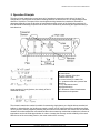
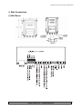
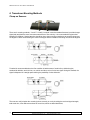
BE6000 Series Ultrasonic Flow Meter BE6000 Ultrasonic Flow Meter O&M Manual 2 Flomotion Systems, Inc. ~ FlomotionSystems.com BE6000 Ultrasonic Flow Meter O&M Manual Installation and Operation Manual BE6000 Series Ultrasonic Transit-Time Flow Meter AUGUST 2009 Flomotion Systems, Inc. 586 N. French Rd. Amherst, NY 14228 U.S.A. 716-691-3941 800-909-3569 www.FlomotionSystems.com Flomotion Systems, Inc. ~ FlomotionSystems.com 3 BE6000 Ultrasonic Flow Meter O&M Manual User Manual BE6000 Ultrasonic Flow Meter Contents I. Introduction _________________________________________________________________ 6 0H 41H 1. Preface __________________________________________________________________________ 6 1H 42H 2. Characteristics ___________________________________________________________________ 6 2H 43H 3. Operation Principle _______________________________________________________________ 7 3H 44H 4. Typical Applications _______________________________________________________________ 8 4H 45H 5. Packing List______________________________________________________________________ 8 5H 46H 6. Technical Specifications ____________________________________________________________ 9 6H 47H 7. Power Connection _________________________________________________________________ 9 7H 48H 8. Cables__________________________________________________________________________ 10 8H 49H (1) Power Cable___________________________________________________________________________ 10 (2) Output Signal Cable_____________________________________________________________________ 10 (3) Cable between transducer and processor _____________________________________________________ 10 9H 50H 10H 51H 11H 52H 9. Wire Connections ________________________________________________________________ 11 12H 53H (1) Wall Mount ___________________________________________________________________________ 11 13H 54H II. Installation and Operation ____________________________________________________ 12 14H 55H 1. Selecting the Measurement Point ___________________________________________________ 12 15H 56H 2. Setting the Parameters ____________________________________________________________ 12 16H 57H 3. Rapid Setup Procedure ___________________________________________________________ 13 17H 58H 4. How to Go into a Specific Window __________________________________________________ 13 18H 59H 5. Transducer Mounting Distance_____________________________________________________ 13 19H 60H 6. Transducer Mounting Methods ____________________________________________________ 14 20H 61H (1) Signal Strength & Quality (M90) __________________________________________________________ 15 (2) Total Travel Time and Time Difference (M93)________________________________________________ 15 (3) Time Rate (TOM/TOS* 100, M91)_________________________________________________________ 15 21H 62H 22H 63H 23H 64H 6. Selecting a Location for Transducer Mounting ________________________________________ 16 24H 65H Preparing the Pipe Surface __________________________________________________________________ 16 25H 66H III. Display Windows ___________________________________________________________ 17 26H 67H 1. Summary _______________________________________________________________________ 17 27H 68H 2. Descriptions_____________________________________________________________________ 18 28H 69H (1) Flow/Totalizer Displays__________________________________________________________________ 18 (2) Initial Setup ___________________________________________________________________________ 20 29H 70H 30H 71H III. Trouble Shooting___________________________________________________________ 39 31H 72H Power-On self-test information, Causes and Solutions ____________________________________ 39 32H 73H Error Code Causes and Solutions _____________________________________________________ 40 33H 4 74H Flomotion Systems, Inc. ~ FlomotionSystems.com BE6000 Ultrasonic Flow Meter O&M Manual Appendix 1. RS-232 Command Protocol ___________________________________________ 41 34H 75H Appendix 2. Sound Velocity and Viscosity of Liquids _________________________________ 42 35H 76H Appendix 3. Sound Velocity for Various Common Materials __________________________ 43 36H 77H Pipe Material______________________________________________________________________ 43 37H 78H Liner Material_____________________________________________________________________ 43 38H 79H Appendix 4. Sound Velocity in Water (1 ATM) at different temperatures _________________ 44 39H 80H Appendix 5. Pipe Dimensions and Weights _________________________________________ 45 40H 81H Flomotion Systems, Inc. ~ FlomotionSystems.com 5 BE6000 Ultrasonic Flow Meter O&M Manual I. Introduction 1. Preface Welcome to BE6000 series ultrasonic flow meter. Please read this instruction manual thoroughly before installation and operation. BE6000 ultrasonic flow meter is a time-difference type ultrasonic flow meter, whose transducers are mounted clamped on pipe. It measures clean, well-distributed flows of liquids those content of suspended particles is not very high. The system is configured as below; • Sensor Set: A pair of ultrasonic transducers mounted on the external surface on a pipe. • Processor: The processor and the transducers are connected by two double shield high frequency cables. The processor can be monitored and controlled remotely through a PC connected via Internet. The following illustrates the configuration of the processor unit and the transducer sets; 2. Characteristics BE6000 ultrasonic flow meter is based on single-board technology featuring high accuracy, reliability and repeatability. The merits it provides above else are; • • • • 6 Transducers are not intrusive. Therefore there’s no pressure drop. They are mounted on the outside wall of the pipe. Advanced intelligent instrumentation, processing and printing (logging) according to user requirements. Almost all common flow units are used. It uses normal power, built-in battery or DC power, etc. It uses the most advanced direct time measurement method with the resolution of 0.2 ns. Coupled with the advanced data processing functions, it provides high level of linearity. Various output options available including analog current output, frequency output, RS-232 serial output, relay output, etc. The output options can be set by a menu or via a PC connected to the processor through a RS-232C. Flomotion Systems, Inc. ~ FlomotionSystems.com BE6000 Ultrasonic Flow Meter O&M Manual 3. Operation Principle This time-of-travel (transit-time) meter has a pair of transducers mounted on each side of the pipe. The configuration is such that the sound waves traveling between the devices are at a 45- degree angle to the direction of liquid flow. The speed of the sound signal traveling between the transducers increases or decreases depending upon the direction of transmission and the velocity of the liquid being measured. A time-differential relationship proportional to the flow can be obtained by transmitting the signal alternately in both directions. As per equation (1) and (2) above, the velocity of flow is calculated as below; Where M- travel times D- inner diameter of the pipe θ transmission angle C0- sound velocity in a static fluid TUP- upstream travel time (reverse flow direction) TDOWN- downstream travel time(flow direction) ΔT- difference of travel time between downstream and upstream The ultrasonic transit-time method is suitable for measuring single-phase, pure liquids without entrained air bubbles. In industrial sites, the liquids may contain a certain level of impurities and flow conditions are often not very uniform, thereby negatively affecting the performance of the ultrasonic flow meters. But our BE6000 ultrasonic flow meter adopts the most advanced direct time measuring method that considers the influence of temperature and crude inside pipe situation in order to increase the accuracy and the reliability of the result. With the use of the zero setting function, the meter renders 0.5% accuracy. Flomotion Systems, Inc. ~ FlomotionSystems.com 7 BE6000 Ultrasonic Flow Meter O&M Manual 4. Typical Applications • • • • • • • • Water supply, drainage, water purification facility Oil field and petrochemical plants Power plants(thermal and hydro power plants) Steel factory and mining industries Food and beverage plants Paper mills HVAC Etc. 5. Packing List Items included are as follows; • 1 processor • 1 set of transducers(2 ea) • 1 transducer mounting chain • 1 couplant • 1 instruction manual • Test certificate 8 Flomotion Systems, Inc. ~ FlomotionSystems.com BE6000 Ultrasonic Flow Meter O&M Manual 6. Technical Specifications Classification Pipe Fluid Performance/Parameter Materials Inner Diameter Straight Pipe Section Requirement Types Turbidity Temperature Flow Velocity Transducer Pipe Size Range Mounting Method Cable Length Flow Computer Display Keyboard Mounting Output Power Operating Condition Dimension Weight Temperature Humidity Performance Accuracy Repeatability Linearity Steel, Stainless Steel, Cast Iron, Plastics, Concrete, etc. 0.5 to 236 in. (15 ~ 6000mm) 10D upstream, 5D downstream (required length may be longer depending on site conditions) Clean, sonically conductive Smaller than 10,000ppm(mg/l) with a low level of air bubble content -4° to 140° F (-20° to 60°) -53 to +53° F (-16 to +16 m/s) S: 0.5 to 4 in. (15 ~ 100mm) M: 2 to 40 in. (50 ~ 1000mm) L: 12 to 236 in. (300 ~ 6000mm) ‘V’ method: Suitable for pipe sizes 16 in. (400mm) or smaller ‘Z’ method: Suitable for pipe sizes 10 in. (250mm) or larger 16 ft (5m) Std. (longer lengths available) Alphanumeric 2 x 20 digit backlight LCD 4 x 4 keypad Wall Mount or optional Panel Mount 4-20mA or 0-20mA analog output, frequency output (12-9999Hz), relay, serial output. Wall Mount: 120VAC & 24VDC Panel Type : 120VAC Wall Mount: 9.9 x 3.6 x 3.2 in. (251 x 92 x 80mm) 7 lbs. (3kg) Wall Mount Flow Computer: -4 to 158º F (-20 to 70º C) Transducer: -4 to 140º F (-20 to 60º C) Flow Computer: 85% RH at 104º F (40º C) Transducer: 98% RH at 104º F (40º C) (Able to operate immersed in water depth smaller than 3m) ±1.0% of reading above ±1 fps ±0.2% at 1 to 53 fps (0.3 ~ 16m/s) 0.5% 7. Power Connection Attention: Meter can be badly damaged if a different power from what was specified is supplied. Careful attention is advised. The meter can use standard 120VAC or 24VDC power supply. By default, the meter is provided with the standard 120VAC power type. Therefore, should the user want 24VDC model, such should be indicated when ordering. Flomotion Systems, Inc. ~ FlomotionSystems.com 9 BE6000 Ultrasonic Flow Meter O&M Manual 8. Cables Cables should never be spliced or cut. Please use the following cables; (1) Power Cable 3-core or 2-core rubber insulated cable (outer diameter 11mm) (2) Output Signal Cable 2-core or many-core rubber insulated cable (11mm) (3) Cable between transducer and processor 10 Flomotion Systems, Inc. ~ FlomotionSystems.com BE6000 Ultrasonic Flow Meter O&M Manual 9. Wire Connections (1) Wall Mount Flomotion Systems, Inc. ~ FlomotionSystems.com 11 BE6000 Ultrasonic Flow Meter O&M Manual II. Installation and Operation The clamp-on type ultrasonic flow meter allows for the simplest and the easiest installation of all types of flow meters, though careful attention in selecting the measurement point, inputting pipe parameters, fixing the transducers onto pipe, etc. in order to ensure accurate and reliable measurement of flow is needed. In this chapter, you’ll be introduced to how to select the measurement point, input parameters, select mounting method, etc. 1. Selecting the Measurement Point Selecting the right measurement point is the most important factor for ensuring the accuracy and should be done according to the following steps; (1) Make sure the pipe to be measured is full. (2) Select a location where it allows for straight pipe run of 10D upstream and 5D downstream. In case there’s a pump or a bending section in the upstream, increase the upstream run to 30D in order to allow the flow to fully develop into stable flow profile. (3) Ensure the temperature at the measuring point is within the specified range. (4) Avoid sections where the inner wall of the pipe is scaled or rusted that can negatively affect the performance of the meter. 2. Setting the Parameters In order to get the correct transducer mounting distance (the distance between the front edges of both transducers), verify and set the following parameters; (1) Pipe outer diameter (2) Pipe inner diameter (3) Pipe material (4) Liner (5) Fluid type (6) Transducer type (7) Transducer mounting method type When the above parameters are properly set, the correct transducer mounting distance is calculated and displayed in menu M25. Then the machine searches for proper amplifier gain. After S1, S2, S3 and S4 steps, the machine enters into the normal operation state. 12 Flomotion Systems, Inc. ~ FlomotionSystems.com BE6000 Ultrasonic Flow Meter O&M Manual 3. Rapid Setup Procedure (1) (2) (3) (4) (5) (6) (7) Press [MENU] [1] [1] to enter M11 window, input pipe outer diameter, press [ENT]. Press [▼] to enter M12 window, input wall thickness and press [ENT]. Press [▼] [▼] to enter M14 window and [ENT] [▼] [▲] to select pipe material, and press [ENT]. Press [▼] to enter M16 window and [ENT] [▼] [▲] to select liner material, and press [ENT]. Press [▼] to enter M20 window and [ENT] [▼] [▲] to select fluid type, and press [ENT]. Press [▼] to enter M23 window and [ENT] [▼] [▲] to select the transducer type, and press [ENT]. Press [▼] to enter M24 window and [ENT] [▼] [▲] to select the transducer mounting method, and press [ENT]. (8) Press [▼] to enter M25 window, which will display the correct transducer mounting distance(the distance between the front edges of the transducers). (9) Press [MENU] [0] [1] [ENT], the flow rate and the velocity of the flow will be displayed upon completion of the gain adjusting process. 4. How to Go into a Specific Window The user can enter into specific windows using the [MENU] key followed by a 2-digit code. So, for example, in order to go to window M13, which is the window for inputting the inner diameter of the pipe, press [MENU] [1] [3] [ENT]. 5. Transducer Mounting Distance The distance is measured between the front edges of both transducers. After all the parameters have been set, the distance is shown in M25. Flomotion Systems, Inc. ~ FlomotionSystems.com 13 BE6000 Ultrasonic Flow Meter O&M Manual 6. Transducer Mounting Methods Clamp-on Sensors There are 2 mounting methods, ‘V’ and ‘Z’. Usually V method is used as standard because it provides longer signal path and therefore more accurate measurement of flow velocity. It is recommended for pipes sizes between 25~6000mm. Special attention should be given when mounting transducers to ensure that sensors are aligned in direct line and along the center of the pipe and the transducer mounting line should be aligned. Z method is recommended when the flow condition is bad because of scale built up inside the pipe, entrained air bubbles, too thick liner, etc. which can induce a lot of noise into signal. Using this method, the signal is dispersed in a straight path reducing the possibility of noise induction. The user can verify whether the mounting is done correctly or not by checking the received signal strength, total travel time, time difference and rate of travel time, which are described below; 14 Flomotion Systems, Inc. ~ FlomotionSystems.com BE6000 Ultrasonic Flow Meter O&M Manual (1) Signal Strength & Quality (M90) The signal strength is indicated by a number between 0.00 ~ 99.9. 0.00 means no signal received and 99.9 means the signal strength is at the maximum. It should be larger than 60.0 for normal operation. The signal quality Q is indicated by a number between 0.00 ~ 99.9. 0.00 indicates that the signal is at its lowest level and 99.9 the highest. It should be at least 60.00 for normal operation. (2) Total Travel Time and Time Difference (M93) The measurement is taken based on the total travel time and the time difference. They are also indicative of the condition of the installation of the transducers. Under normal condition, the time difference should be smaller than 10%. If the pipe size is very small or the flow velocity is very low, the wave may be a little bigger. When the wave is too big, so are the flow and the velocity. This is said to be of bad signal quality, which may result from bad pipe condition, incorrect installation of the transducers or incorrect parameters set. (3) Time Rate (TOM/TOS* 100, M91) This is used to confirm whether the transducers are located with the correct interval. This should indicate 100 ±3%. Flomotion Systems, Inc. ~ FlomotionSystems.com 15 BE6000 Ultrasonic Flow Meter O&M Manual 6. Selecting a Location for Transducer Mounting 1. Locate the transducers downstream from the center of the longest available straight run. A location ten pipe diameters or greater downstream from the nearest bend will provide the best flow profile conditions. 2. Do not install the transducers downstream from a throttling valve, a mixing tank, the discharge of a positive displacement pump or any other equipment that could possibly aerate the liquid. The best location will be as free as possible from flow disturbances, vibration, sources of heat, noise, or radiated energy. 3. Avoid mounting the transducers on a section of pipe with any external scale. Remove all scale, rust, loose paint etc., from the location. Do not mount the transducers on a surface aberration (e.g., pipe seam, etc.). 4. Do not mount transducers from different ultrasonic flow meters on the same pipe. Also, do not run the transducer cables in common bundles with cables from communication equipment, other electronic systems or any type of ultrasonic equipment. You can run these cables through a common conduit ONLY if they originate at the same flowmeter. 5. Never mount transducers under water, unless you order submersible units and you install them in accordance with factory instructions. 6. Avoid mounting transducers on the top or bottom of a pipe. The ideal placement is either the nine o’clock or three o’clock position for Reflect Mode, or one transducer at nine o’clock and the other at three o’clock for Direct Mode. Mounting on a vertical pipe is recommended only if flow is in the upward direction. Preparing the Pipe Surface 1. Pick a mounting location with the longest straight run. You must have easy access to at least one side of your pipe. The mounting location must remain full, even at zero flow. 2. Decide on your mounting mode (Z or V). Use V Mode whenever possible. 3. After receiving the spacing dimensions from the Installation Menu, prepare the pipe surface. Degrease the surface, if necessary, and remove any grit, corrosion, rust, loose paint, etc. Use abrasive material provided to create a clean contact surface for the transducers. 4. Refer to the next sections for illustrated instructions on how to locate each area to be cleaned and how to use each mounting option. Please note that the instructions show vertical mounting for clarity purposes only. Do not install transducers on the top of a pipe. NOTE: In the following paragraphs, references to the 9 o’clock position indicate the section of the pipe that is closest to you. 1. Install transducers in accordance with instructions in the manual and the appropriate installation drawings. 2. Apply a 1/4” wide bead of couplant edge-to-edge down the TRANSDUCERS center of the emitting surface of the transducers. 3. Follow the instructions in the manual for installing the transducers. 4. For permanent applications allow the RTV type couplant to cure. It cures at room temperature upon exposure to moisture in the air. During the cure, it releases acetic acid Apply 1/4” bead of couplant (a vinegar like odor). It reaches full cure within 24 hours. to emitting surface. 16 Flomotion Systems, Inc. ~ FlomotionSystems.com BE6000 Ultrasonic Flow Meter O&M Manual III. Display Windows 1. Summary All display windows of BE6000 and their descriptions will be discussed in this chapter. The user can enter display windows following the instruction given in Chapter II, i.e. [MENU] [#] [#] to realize the communication between the user and the machine. The followings are the display menus, which are defined by 2 numbers on the left column • Flow Totalizer/Display Menu 00 Flow Rate/Net Totalizer 01 Flow Rate/Velocity 02 Flow Rate/POS Totalizer 03 Flow Rate/NEG Totalizer 04 Date Time/Flow Rate 05 Energy Flow Rate/Totalizer 06 AI1, AI2 (Analog Input) 07 AI3, AI4 08 System Error Code 09 Net Flow Today • Initial Setup Menu 10 Pipe Outer Perimeter 11 Pipe Outer Diameter 12 Pipe Wall Thickness 13 Pipe Inner Diameter 14 Pipe Material 15 Pipe Sound Velocity 16 Liner Material 17 Liner Sound Velocity 18 Liner Thickness 19 Inside ABS Thickness 20 Fluid Type 21 Fluid Sound Velocity 22 Fluid Viscosity 23 Transducer Type 24 Transducer Mounting 25 Transducer Spacing 26 Parameter Setups 27 Current Section Area 28 Holding for Poor Signal 29 Empty Pipe Setup • Flow Unit Setup 30 Measurement Unit in 31 Flow Rate Unit 32 Totalizer Unit 33 Totalizer Multiplier 34 NET Totalizer 35 POS Totalizer 36 NEG Totalizer 37 Totalizer Reset 38 Manual Totalizer 39 Language Selection • Option Setup Menu 40 Damping 41 Low Flow Cutoff 42 Set Zero 43 Reset Zero 44 Manual Zero Point 45 Scale Factor 46 Network IDN 47 System Lock 48 Keypad Lock Code • Output/Input Setup Menu 50 Logger Option 51 Logger Time Setups 52 Print only to RS-232C 53 Analog Input AI5 54 AI5 Value Range 55 CL Mode Select 56 CL 4mA Output Value 57 CL 20mA Output Value 58 CL Checkup 59 CL Current Output 60 Date and Time 61 Software Version and ESN 62 RS-232C Setup 63 AI1 Value Range 64 AI2 Value Range 65 AI3 Value Range 66 AI4 Value Range 67 FO Frequency Range 68 Low FO Flow Rate 69 High FO Flow Rate 70 LCD Backlight Option 71 LCD Contrast 72 Working Timer Flomotion Systems, Inc. ~ FlomotionSystems.com 73 Alarm #1 Low Value 74 Alarm #1 High Value 75 Alarm #2 Low Value 76 Alarm #2 High Value 77 Buzzer Setup 78 OCT Output Setup 79 Relay Output Setup • Energy Meter Menu 80 Flow Batch Control Source 81 Flow Batch Controller 82 Date Totalizer 83 Automatic Amending 84 Energy Unit Select 85 Temperature Select 86 Specific Heat 87 Energy Totalizer ON/OFF 88 Energy Multiplier 89 Reset Energy Totalizer • Diagnostics Menu 90 Signal Strength and Quality 91 TOM/TOS*100 92 Fluid Sound Velocity 93 Total Time and Delta Time 94 Reynolds No. and Factor • Others + 0 Power ON/OFF Time + 1 Total Working Time + 2 Last Power Time + 3 Last Flow Rate + 4 ON/OFF Times + 5 Calculator + 6 Velocity Changing + 7 Protocol Select + 8 Receive Shape +9 17 BE6000 Ultrasonic Flow Meter O&M Manual 2. Descriptions (1) Flow/Totalizer Displays • Flow Rate/Net Totalizer(M00) Flow -10.023 m3/h *R NET 1342 x 0.01 m3 This window is only for display. The selection of the unit is made in M31 and M32 windows. If the NET totalizer is unselected, the value shown in the window is replaced by the totalizer last time. Add the negative totalizer to the positive totalizer to get the net totalizer. • Flow Rate/Flow Velocity(M01) Flow -10.023 m3/h *R VEL -0.3215 m/s This window is only for display. The selection of the unit is made in M31 and M32 windows. • Flow Rate/Positive Totalizer(M02) Flow -10.023 m3/h *R POS +1342 x 0.01 m3 This window is only for display. The selection of the unit is made in M31. If the POS totalizer is unselected, the value shown in the window is replaced by the POS totalizer last time. • Flow Rate/Positive Totalizer(M03) Flow -10.023 m3/h *R NEG -1342 x 0.01 m3 This window is only for display. The selection of the unit is made in M31. If the POS totalizer is unselected (M36), the value shown in the window is replaced by the NEG totalizer last time. • Date and Time/Flow Rate(M04) 05-10-20 10:10 *R Flow 10.023 m3/h This window is for displaying current date, time and flow rate. The time and date can be entered in M60. 18 Flomotion Systems, Inc. ~ FlomotionSystems.com BE6000 Ultrasonic Flow Meter O&M Manual • Energy/Total Energy(M05) EFR +253.27 0kc/s *R E.T +12213414EO GJ This window shows energy flow and the totalizer. Details on measuring energy are described in “Energy Measurement”. • Analog Input AI1 and AI2(M06) AI1= 4.0000:20.000 AI2= 8.0000:40.000 This window shows analog inputs AI1 and AI2 in currents that represent temperature, pressure or liquid level, etc. • Analog Input AI3 and AI4(M07) AI3= 4.0000:20.000 AI4= 8.0000:40.000 This window shows analog inputs AI3 and AI4 in currents that represent temperature, pressure or liquid level, etc. • System Error Codes(M08) *R System Normal It shows the status of operation and corresponding status (or error) code. There are several error codes, whose implications and solutions are discussed in “ERROR SEARCHING”. • Net Flow Today(M09) Net Flow of Today 358.34m3 This window displays the net totalizer of the day. Flomotion Systems, Inc. ~ FlomotionSystems.com 19 BE6000 Ultrasonic Flow Meter O&M Manual (2) Initial Setup • Pipe Outer Perimeter(M10) Input the Outer Perimeter of Pipe 518.363mm Input the outer perimeter of the pipe. If the outer diameter is available, please ignore this value and input the outer diameter of the pipe in M11. • Pipe Outer Diameter(M11) Input the Outer Diameter of Pipe 165mm Input the outer diameter directly or input the outer perimeter in M10. The value should be between 10mm and 6,000mm. Attention: Either outer diameter or outer perimeter is ok. • Pipe Wall Thickness(M12) Pipe Wall Thickness 5mm Input the pipe wall thickness, if available, or skip this and go into M13. • Inner Diameter(M13) Pipe Inner Diameter 155mm Input the inner diameter. If you have input other diameter or outer perimeter and wall thickness, skip this window. Either the wall thickness or the inner diameter is ok. • Pipe Material(M14) Pipe Material 0. Carbon Steel You can select one of the following materials from the list provided; 0. Carbon Steel 1. Stainless Steel 2. Cast Iron 3. Ductile Iron 4. Copper 20 5. PVC 6. Aluminum 7. Asbestos 8. Fiber Glass- Epoxy 9. Other Flomotion Systems, Inc. ~ FlomotionSystems.com BE6000 Ultrasonic Flow Meter O&M Manual If ‘9. Other’, you must input the corresponding sound velocity of the material in M15. • Pipe Sound Velocity(M15) Pipe Sound Velocity 1300.5 m/s Use this menu only when ‘9. Other’ is selected in M14. This menu is not activated if ‘9. Other’ is not selected in M14. • Liner Material(M16) Liner Material 0. No Liner You can select one of the following materials from the list provided; 0. No Liner 1. Tar Epoxy 2. Rubber 3. Mortar 4. Polypropylene 5. Polystrol 6. Polystyrene 7. Polyester 8. Polyethylene 9. Ebonite 10. Teflon 11. Other If ‘11. Other’, you must input the corresponding sound velocity of the material in M17. • Liner Sound Velocity(M17) Liner Sound Velocity 3300.5 m/s Use this menu only when ‘11. Other’ is selected in M16. • Liner Thickness(M18) Liner Thickness 10mm Only when a liner is selected in M16, this menu will be activated. • Inside ABS Thickness(M19) Inside ABS Thickness 0 Input ABS roughness coefficient. Not used. Reserved for future use. • Fluid(M20) Flomotion Systems, Inc. ~ FlomotionSystems.com 21 BE6000 Ultrasonic Flow Meter O&M Manual Fluid Type 0. Water You can select one of the following fluids from the list provided; 0. Water 8. Other 1. Sea Water 9. Diesel Oil 2. Kerosene 10. Caster Oil 3. Gasoline 11. Peanut Oil 4. Fuel Oil 12. Gasoline #90 5. Crude Oil 13. Gasoline #93 6. Propane (-45°C) 14. Alcohol 7. Butane (0°C) 15. Water (125°C) If ‘8. Other’ is selected; input the corresponding sound velocity of the fluid in M21. • Fluid Sound Velocity(M21) Fluid Sound Velocity 1600.0m/s Enter the sound velocity of the fluid you chose in M20. This is activated only when ‘8. Other’ is selected in M20. • Fluid Viscosity(M22) Fluid Viscosity 1.0054 cSt Enter the viscosity of the fluid you chose in M20. This is activated only when ‘8. Other’ is selected in M20. • Transducer Type(M23) Transducer Type 0. Standard – M Select one of the transducer types from the list provided; 0. Standard – M 1. Plug-in Type c 2. Standard – S 3. User’s Own Type 4. Standard - B 5. Plug-in Type B45 6. Standard – L If you select ‘3. User’s Own Type, you should enter a group of transducer parameters such as sound wedge angle, sound wedge velocity, ultrasonic delay and distance between the edge of the transducer and sound. • Transducer Mounting Method(M24) Transducer Mounting 0. V 22 Flomotion Systems, Inc. ~ FlomotionSystems.com BE6000 Ultrasonic Flow Meter O&M Manual Select one of the transducer mounting types from the list provided; 0. V Method 1. Z Method 2. N Method (for small pipes) 3. W Method (for very small pipes) • Transducer Distance(M25) Transducer Spacing 50.00mm This window is only for display of the transducer mounting distance that was calculated based on the parameters input in the foregoing menus. The distance is between the front edges of the transducers. • Parameter Save/Load(M26) Parameter Setups 0. Entry SAVE The pipe parameter data can be saved and loaded for a quick set up. A total of 18 sets of setup data can be stored and loaded. The following menus are provided; 0. Entry SAVE 1. Entry LOAD 2. Browse When 0 is pressed and then ENTER is pressed, the window will show the address number and the data stored in that address. The data can be browsed using up and down keys and edited. Press ENTER to save the data. If a set of parameter data is loaded, the system will calculate the parameters and show the sensor distance in M25 window. • Current Section Area(M27) Current Section Area 1963.5 mm2 The section area of the flow will be displayed. • Data Holding(M28) Holding With Poor Signals Yes Select “Yes” to hold the last good flow signal displayed if the flow meter experiences a poor signal condition. This function will allow continued data calculation without interruption. • Empty Pipe Setup(M29) Empty Pipe Setup 0 This value is used to solve the problem of the empty pipe. Even when the pipe is empty, the flow meter will show “Normal Working” for the signals that are transmitted and reflected through the pipe wall. In order to Flomotion Systems, Inc. ~ FlomotionSystems.com 23 BE6000 Ultrasonic Flow Meter O&M Manual avoid this, set the lowest signal strength threshold to about 30~40, below which the system stop measurement because the pipe is deemed to be empty. Measurement Unit (M30) Measurement Units In 0. Metric The following options are provided; 0. Metric 1. English The default is Metric. Flow Rate Units(M31) Flow Rate Units m3/h The following flow units and time units are available; Flow Units 0. Cubic Meters (m3) 1. Liters (l) 2. (American) Gallons 3. Imperial Gallons 4. Million Gallons Time Units /hour /day /min 5. Cubic Feet (cf) 6. (American) Barrels 7. Imperial Barrels 8. Oil Barrels (ob) /sec • Totalizer Units(M32) Totalizer Units Cubic Meters (m3) Select totalizer units. The available unit options are the same as those found in M31. The user can select units as required. Factory default is cubic meters. • Totalizer Multiplier Options(M33) Totalizer Multiplier m3/h The totalizer multiplier acts as the function to increase the totalizer indicating range. Meanwhile, the totalizer multiplier can be applied to the positive totalizer, negative totalizer and net totalizer at the same time. The followings options are available; 0. X 0.001 (1E-3) 24 4. X10 Flomotion Systems, Inc. ~ FlomotionSystems.com BE6000 Ultrasonic Flow Meter O&M Manual 1. X 0.01 2. X0.1 3. X1 5. X100 6. X1000 7. X10000 (1E+4) Factory default factor is x1. • ON/OFF Net Totalizer (M34) Net Totalizer ON On/off net totalizer. “ON” indicates that the totalizer is turned on, while “OFF” indicates it is turned off. When it is turned off, the net totalizer display in M00 will not change. Factory default is “ON”. • ON/OFF Positive Totalizer (M35) POS Totalizer ON On/off positive totalizer. “ON” indicates the flowmeter starts to totalize the value. When it is turned off, the positive totalizer displays M02 won’t change. Factory default is “ON”. • ON/OFF Negative Totalizer (M36) NEG Totalizer ON On/off negative totalizer. “ON” indicates the flowmeter starts to totalize the value. When it is turned off, the negative totalizer displays M03 won’t change. Factory default is “ON”. • Totalizer Reset(M37) Totalizer Reset? Selection Totalizer reset; all parameters are reset. Press [ENTER]; move UP or DOWN arrow to select “YES” or “NO”. After “YES” is selected, the following operations are available; None All NET POS NEG If it is necessary to recover the factory default, press [.][Å] keys after the above-mentioned characters are displayed on the screen. • Manual Totalizer(M38) Flomotion Systems, Inc. ~ FlomotionSystems.com 25 BE6000 Ultrasonic Flow Meter O&M Manual Manual Totalizer Press ENT when ready The manual totalizer is a separate totalizer. Press [ENTER] to start, and press [ENTER] to stop it. It is used for flow measurement and calculation. • Damping(M40) Damping 10 sec The damping factor ranges from 0~999 seconds. 0 indicates no damping; 999 indicate the maximum damping. Damping functions to display the data smoothly. Its principle is the same as that in a single-section RC filter. The damping factor value corresponds to the circuit time constant. Usually a damping factor of 3 to 10 is recommended in applications. • Low Flow Cutoff Value(M41) Low Flow Cutoff Val. 0.01 m/s Low Flow Cutoff is used to make the system display as “0” value at lower and smaller flows to avoid any inefficiency in totalizing. For instance, if the cutoff value is set as 0.03, system will take all the measured flow values of ±0.03 as “0”. Usually 0.03 is recommended in most applications. • Set Zero(M42) Set Zero[42 Press ENT to go When the fluid is in the static state, the displayed value is called “Zero Point”. When “Zero Point” is not at zero in the flowmeter, the difference is going to be added into the actual flow values and measurement differences will occur in the flow meter. Set Zero must be carried out after the transducers are installed and the flow inside the pipe is in the absolute static state (no liquid movement in the pipe). Thus, the “Zero Point” resulting from different pipe mounting locations and parameters can be eliminated. The measuring accuracy at low flow is enhanced consequently. Press [ENT], wait for the processing instructions at the bottom right corner to reach 0. Set zero within the existing flow may cause the flow to be displayed as “0”. If so, it can be recovered via M43. • Reset Zero(M43) Reset Zero [43 No Select “YES”; reset “Zero Point” which was set by the user. • Manual Zero Point(M44) 26 Flomotion Systems, Inc. ~ FlomotionSystems.com BE6000 Ultrasonic Flow Meter O&M Manual Manual Zero Point [44 0m3/h This method is not commonly used. It is only suitable for experienced operators to set zero under conditions where it is not preferable to use other methods. Enter the value manually to add to the measured value to obtain the actual value. For instance: Actual Measured Value = 250 m3/h Value Deviation = 10 m3/h Displayed Value = 240 m3/h Normally, set this value as “0”. • Scale Factor(M45) Scale Factor [45 1 The scale factor is used to modify the measurement results. Factory default is 1. The user can enter a numerical value other than “1” according to calibration results. • Network IDN(M46) Network IDN [46 88 Input system identifying code, these numbers can be selected from 0 ~ 65535 except that 13 (0DH ENTER), 10(0AH New Line), 42(2AH *) and 38(26H&). System IDN is used to identify a unit in network. • System Lock(M47) System Lock [47 = Unlock Lock the flowmeter. Once the system is locked, any modification is prohibited in the system. However, the parameter is readable, so as to protect proper operation of the instrument. “Unlock” by the password only. The password is composed of 1 to 4 numbers. (Please contact us if the password is forgotten) • Keypad Lock Code (M48) Low Flow Cutoff Val. 0.01 m/s The Keypad Lock function is used to avoid any operation errors by unauthorized personnel. (Please contact us if the password is forgotten) • Logger Option (M50) Flomotion Systems, Inc. ~ FlomotionSystems.com 27 BE6000 Ultrasonic Flow Meter O&M Manual Logger Option [50 OFF Sets the printer on/off. When “ON” is selected. The following options will be displayed for further options(Use key to move to next item); 0. Date and Time (OFF) 1. System Status (OFF) 2. Current Window (OFF) 3. Flow Rate (ON) 4. Velocity (OFF) 5. NET Totalize (OFF) 6. POS Totalize (OFF) 7. NEG Totalize (OFF) 8. Signal Strength (OFF) 9. Energy Flow Rate (OFF) 10. Energy Totalize (OFF) 11. AI1 (OFF) 12. AI2 (OFF) 13. Working Timer (OFF) 14. Flow Today (OFF) Press ENT to select and set the setting. • Logger Time Setups(M51) Logger Time Setups [51 Start Time = 00:00:00 Input Start Time, Interval and Duration. If you set the Start Time as **:**:**, the instrument will start logging on from now on. If you set it to 23:10:10, it will start logging from 23:10:10. If the Interval is set to **:**:**, the logging will never stop. The minimum logging interval is 1 second and the maximum is 24 hours. • Print to RS-232C(M52) Print to RS-232C [52 This menu is fixed. That means the logging data will always be available at RS-232C port. • Display AI5(M53) Analog Input AI5 [53 AI5=4.0000:20.00 Displays the electric current of AI5 and its corresponding parameters such as temperature, pressure or level. • AI5 Range(M54) AI Value Range [54 10-100 To input scale range of temperature, pressure or level for the analog input of 4-20mA. For example, the value 10 in the above box represents 4mA and 100 20mA. • Current Output Selection(M55) 28 Flomotion Systems, Inc. ~ FlomotionSystems.com BE6000 Ultrasonic Flow Meter O&M Manual CL Mode Select [55 0.4-20mA 0. 4-20mA 1. 0-20Ma 2. 0-20mA Via RS-232 3. 4-20mA vs. Flow 4. 20-4-20mA 5. 0-4-20mA 6. 20-0-20mA 7. 4-20mA vs. Vel. 8. 4-20mA vs. Energy The serial port controls the output according to the command and parameter entered in the RS232 to output a definite current value through the current loop. The command formats are narrated in the command explanations to Serial Port controls. For instance, if it is necessary to output a 6mA current through the current loop, it can be realized by setting M56 to mode “0-20mA Via RS232” and giving a command “AO6(CR)”. This function is able to make the flowmeter operate a control valve conveniently. • 4mA or 0mA Output Value(M56) CL 4mA Output Value[56 0 m3/h Use this window to set the flow value to 4mA or 0mA. The flow unit is the same that was set at M31. • 20mA Output Value(M57) CL 20mA Output Value[57 1200 m3/h Use this window to set the flow value to 20mA. The flow unit is the same that was set at M31. • CL Check Verification(M58) CL Checkup [58 Verification Check if the current loop has been calibrated before leaving the factory. Press ENT, move 5or 6separately to display 0mA, 4mA till 24mA, and at the same time, check with an ammeter to verify that CL output terminals No. 31 and 32 agree with the displayed values. It is necessary to re-calibrate the CL if over the permitted tolerance. For more information, refer to Chapter 3- Operating Instructions. Section 3.29-Analog Output Calibration. • CL Current Output(M59) CL Current Output [59 0.0000mA Display CL current output. The display of 10.0000mA indicates that CL current output value is 10.0000mA. If the difference between displaying value and CL output value is too large, the current loop then needs to be re-calibrated accordingly. Flomotion Systems, Inc. ~ FlomotionSystems.com 29 BE6000 Ultrasonic Flow Meter O&M Manual • Date and Time Settings(M60) YY-MM-DD HH:MM:SS 04-05-05 11:05:05 Date and time modifications are made. The format for setting time setting is 24hours. Press ENT, wait until “>” appears. The modification can then be made. • ESN(M61) Ultrasonic Flowmeter ESN = 35800003 Displays the electronic serial number (ESN) of the instrument. This ESN is the only one assigned to each BE6000 series flow meter ready to leave the factory. The factory uses it for files setup and for management by the user. • Serial Port Setup(M62) RS-232C Setup [62 9600, 8, None To set RS232 port property. The first information is bit rate and can be 110, 150, 300, 600, 1200, 240, 4800 or 9600. The second information is data bit and it can be either 7 or 8. The third information is parity and can be either None, Even or Odd. And the fourth information is stop bit and can be 1, 1.5 or 2. • AI1 Range(M63) AI Value Range [63 10-100 To input scale range of temperature, pressure or level for the analog input of 4-20mA. For example, the value 10 in the above box represents 4mA and 100 20mA. • AI2 Range(M64) AI Value Range [64 10-100 To input scale range of temperature, pressure or level for the analog input of 4-20mA. For example, the value 10 in the above box represents 4mA and 100 20mA. • AI3 Range(M65) AI Value Range [65 10-100 To input scale range of temperature, pressure or level for the analog input of 4-20mA. For example, the value 10 in the above box represents 4mA and 100 20mA. 30 Flomotion Systems, Inc. ~ FlomotionSystems.com BE6000 Ultrasonic Flow Meter O&M Manual • AI4 Range(M66) AI Value Range [66 10-100 To input scale range of temperature, pressure or level for the analog input of 4-20mA. For example, the value 10 in the above box represents 4mA and 100 20mA. • Frequency Output Signal Frequency Range(M67) FO Frequency Range [67 1-1001 To input low(12-9999Hz) and high(12-9999Hz) frequency for the output. Make sure to set OCT to output frequency signal in order to output frequency signal. • Flow Value of Low Frequency Output(M68) Low FO Flow Rate [68 0 m3/h To input flow rate value for the low frequency point. • Flow Value of High Frequency Output(M69) High FO Flow Rate [69 0 m3/h To input flow rate value for the high frequency point. • LCD Back Light Controller (M70) LCD Backlit Option [70 1. Always On LCD can be controlled using this window. “Always On” means the back light will be always on. “Always Off” means always off. “Light for nn” means it will turn on when a key is pressed and will stay on for nn seconds after the keys have been pressed. This option is provided for power saving. • LCD Contrast Controller (M71) LCD Contrast [71 9 To control the LCD contrast. Press ENT and adjust the number using up or down keys, and press ENT again to confirm. • Working Timer (M72) Flomotion Systems, Inc. ~ FlomotionSystems.com 31 BE6000 Ultrasonic Flow Meter O&M Manual Working Timer [72 0000054:34:23 Display the totalized working hours of the unit since last reset. It is displayed by HH:MM:SS. If it is necessary to reset it, press ENT and select “YES”. • #1 Alarm Low Value (M73) Alarm #1 Low Value [73 0 m3/h Input the low value of alarm. When the value falls under this value, it will cause the alarm to be output using hardware OCT or relay as set in M78 and M79. • #1 Alarm High Value (M74) Alarm #1 High Value [74 1600 m3/h Input the high value of alarm. When the value exceeds this value, it will cause the alarm to be output using hardware OCT or relay as set in M78 and M79. • #2 Alarm Low Value (M75) Alarm #2 Low Value [75 0 m3/h Input the low value of alarm. When the value falls under this value, it will cause the alarm to be output using hardware OCT or relay as set in M78 and M79. • #2 Alarm High Value (M76) Alarm #2 High Value [76 1600 m3/h Input the high value of alarm. When the value exceeds this value, it will cause the alarm to be output using hardware OCT or relay as set in M78 and M79. • Beeper Setup (M77) Beeper Setup [77 15. Key Stroking On The following sources can be selected to set off the buzzer; 0. No Signal 1. Poor Signal 2. Not Ready(No*R) 32 9. POS into Pulse 10. NEG into Pulse 11. NET into Pulse Flomotion Systems, Inc. ~ FlomotionSystems.com BE6000 Ultrasonic Flow Meter O&M Manual 3. Reverse Flow 4. AO over 100% 5. FO over 120% 6. Alarm #1 7. Alarm #2 8. Batch Control 12. Energy Pulse 13. On/Off via RS232 14. Fluid Changed 15. Key Stroking On 16. Not Using • OCT Output Setup (M78) OCT Output Setup [78 17. Not Using Set the system to put hardware OCT output when one of the following sources occurs; 0. No Signal 1. Poor Signal 2. Not Ready(No*R) 3. Reverse Flow 4. AO over 100% 5. FO over 120% 6. Alarm #1 7. Alarm #2 8. Batch Control 9. POS into Pulse 10. NEG into Pulse 11. NET into Pulse 12. Energy Pulse 13. FO 14. FO via RS232 15. On/Off via RS232 16. Fluid Changed 17. Not Using • Relay Output Setup (M79) Relay Output Setup [79 15. Not Using Set the system to put Relay output when one of the following sources occurs; 0. No Signal 1. Poor Signal 2. Not Ready(No*R) 3. Reverse Flow 4. AO over 100% 5. FO over 120% 6. Alarm #1 7. Alarm #2 8. Batch Control 9. POS into Pulse 10. NEG into Pulse 11. NET into Pulse 12. Energy Pulse 13. On/Off via RS232 14. Fluid Change 15. Not Using • Flow Batch Control Setup (M80) Flow Batch CTRL in 0. Key Input Select the batch control type. Available options are as follows; 0. Key Input 1. AI1 Up Edge 2. AI1 Down Edge 3. AI2 Up Edge 4. AI2 Down Edge 5. AI3 Up Edge 6. AI3 Down Edge 7. AI4 Up Edge Flomotion Systems, Inc. ~ FlomotionSystems.com 33 BE6000 Ultrasonic Flow Meter O&M Manual • Flow Batch Controller (M81) Flow Batch Controller 10000 x 1m3 The internal batch controller in the system is able to control the input signals through keypad or analog input. Output signals can be transmitted through OCT or relay. The flow batch value can be modified in this window. The screen will enter the batch control display as soon as the modification is completed. • Date Totalizer (M82) Date Totalizer [82 0. Day In this window, it is possible to review the historical flow data totalizer for any day for the last 64 days, any month for last 64 months and any year for last 5 years. Press ENT, use UP or DOWN key to review totalizer in days, months and years. Use UP or DOWN key to review the flow total for a specific day, month or year. For instance, to display the flow total for May 17, 2005, the display “-----------“ at the upper right corner of the screen indicates that it was working properly the whole day. On the contrary, if “G” is displayed, it indicates that the instrument gain was adjusted at least once. Probably it was offline once on that day. If “H” is displayed, it indicates that poor signal was detected at least once. Also, it indicates that the operation was interrupted or problems occurred in the installation. For details, please refer to Chapter 5 – Error Diagnoses 0. Day 1. Month 2. Year • Automatic Flow Correction (M83) Automatic Correction ON With the function of automatic flow correction, the flow lost in an offline session can be estimated and automatically adjusted. The estimate is based on the average value, which is obtained from flow rate before going offline and flow measured after going online the next time, multiplied times the time period that the meter was offline. Select “No” to cancel this function. • Energy Unit Selection (M84) Energy Unit Select [84 0. Giga Joule(GJ) Select GJ or K.C as energy unit. The default is GJ. • Energy Temperature Source Selection (M85) 34 Flomotion Systems, Inc. ~ FlomotionSystems.com BE6000 Ultrasonic Flow Meter O&M Manual Temperature Select 0. From AI1, AI2 Select the sources for temperature signals when measuring energy. The following 2 options are provided; 0. From AI1, AI2 1. Fixed Difference If “Fixed Difference” is selected the value should be entered manually through keypad. • Specific Heat (M86) Specific Heat Select 0.0041868 GJ/m3oC Select one of the following 2 kinds of specific heat; 0. GB 1. Fixed Specific Heat Normally, 0.004186 GJ/ m3o C(=1000 kcal/ m3o C). Use M+9 to check the current temperature and calorie. • Energy Totalizer Switch (M87) Energy Totalizer ON/OFF ON Turn on/off the energy totalizing function. • Energy Totalize Multiplier (M88) Energy Multiplier [88 4. xl Select the energy totalize multiplier. 10-4 – 106 (E-4 – E-6) • Reset Energy Totalize (M89) Reset Energy Totalize NO Select YES to reset energy accumulation. • Signal Strength and Signal Quality (M90) Strength+Quality [90 UP:00.0 DN:00.0 Q=00 Display the measured signal strength and signal quality Q value upstream and downstream. Signal strength is indicated from 00.0~99.9. A reading of 00.0 indicates no signal detected, while 99.9 indicates maximum signal strength. Normally the signal strength should be > 60.0. Signal Quality Q is indicated 00~99. Flomotion Systems, Inc. ~ FlomotionSystems.com 35 BE6000 Ultrasonic Flow Meter O&M Manual Therefore, 00 indicates the poorest signal while 99 indicates the best signal. Normally signal quality Q value should be better than 60. • TOM/TOS*100 (M91) TOM/TOS*100 [91 0.0000 Display the ratio between the actual measured transmit time and the calculated transmit time according to customer’s requirement. Normally the ratio should be 100 ±3%. If the difference is too large, the user should check if the parameters are entered correctly, especially the sound velocity of the fluid and the installation of the transducers. This data is of no use before the system is ready. • Fluid Sound Velocity (M92) Fluid Sound Velocity 0.0000 m/s Display the measured fluid sound velocity. Normally this value should be approximately equal to the entered value in M21. If the difference is too large, it probably results from an incorrect value entered in M21 or improper installation of the transducers. • Total Time and Delta Time (M93) Total Time, Delta Time 8.9149uS, -171.09nS Display the measured ultrasonic average time (unit: μS) and delta time of the upstream and downstream (unit: nS) time. The velocity calculation in BE6000 ultrasonic flowmeter is based on the two readings; especially the delta time will best indicate if the instrument is running steadily. Normally the fluctuation in the ration of the delta time should be lower than 20%; otherwise, the system may not run steadily. It is, then, necessary to check if the transducers are installed properly or if the parameters have been entered correctly. • Reynolds Number and Factor (M94) Reynolds Number [94 0.0000 1.0000 Displays the Reynolds number that is calculated by the system and the factor that is set currently by the system. Normally this scaling factor is the average of line and surface velocity factor inside the pipe. • Print Commands (M97, M98, M99, M9.) Press [MENU] [9] [7]. Prints the following working parameters as set by the user at the initial set up; - Outer Diameter - Wall Thickness 36 Flomotion Systems, Inc. ~ FlomotionSystems.com BE6000 Ultrasonic Flow Meter O&M Manual - Inner Diameter - Pipe Material - Liner Material - Fluid Type - Sensor Type - Sensor Mounting Type - Sensor Spacing Press [MENU] [9] [8]. Prints diagnostic data. Press [MENU] [9] [9]. Prints contents of the current window. Press [MENU] [9] [.]. Make the printer to pull the paper at 1 row distance. • Power On/Off Time [MENU] + 0 Power On/Off Time M+0 Press ENT when ready To view the power on/off time and flow rate for the last 64 update times to obtain the offline time period and the corresponding flow rate. Enter the window, press ENT to display the last update before the last 64 times of on/off time and flow rate values. “ON” on right hand indicates that time power is on; “00” on the upper left corner indicates “00-07-18 12:40:12” the date time; flow rate is displayed in the lower right corner. • Total Working Hours [MENU] + 1 Total Work Hours [+1] 00000115:12:08 With this function, it is possible to view the total working hours since the flowmeter left the factory. The figure in the above indicates that the total working hours since the flowmeter left the factory is 115 hours 12 minutes and 8 seconds. • Last Power Off Time [MENU] + 2 Last Power Off Time 04-07-12 10:12:02 Display the last power off time. • Last Flow Rate [MENU] + 3 Last Flow Rate [+3 100.43 m3/h Displays the last flow rate. • Calculator [MENU] + 5 Flomotion Systems, Inc. ~ FlomotionSystems.com 37 BE6000 Ultrasonic Flow Meter O&M Manual X=? M=0 0 This window is a calculator which has the ability of functional operation. How to use: Input the first parameter X, then select an operator. If this operation has a second parameter, then input the second parameter Y and put the result of the operation in X. For example, To calculate 1+2, press [MENU] [+] [5] [1] [ENT]. After selecting “+” operator by using [UP/+] key, press [ENT] [2] [ENT]. This calculator also has register function, which can be selected by operator selection. Note: The calculator can be used even when the meter is operating. The measurement result of the meter will not be affected by the calculation. • Fluid Sound Changed [MENU] + 6 Velocity Changing 1 m/s Displays the threshold value of the sound velocity that will trigger the alarm. Namely if the measured sound velocity should be different from the sound velocity stored in the instrument by more than this threshold value. An alarm signal will be generated and transmitted as OCT or relay output. • Compatible Communication Protocol Selection [MENU] + 7 Protocol Select [+7 0. Protocol 0(*Adxx) Select one of two different communications protocols. • Receive Wave Shape [MENU] + 8 Receive Shape To display the wave shape of ultrasonic signals received by the flow meter. In normal conditions, the displayed wave shape should be constant without fluctuations. 38 Flomotion Systems, Inc. ~ FlomotionSystems.com BE6000 Ultrasonic Flow Meter O&M Manual III. Trouble Shooting With highly reliable design, the BE6000 ultrasonic flowmeter has a low failure rate. However, problems may occur as a result of unskillful handling, setting errors or working in an extremely undesirable working condition. For this reason, the meter is equipped with a self-diagnostic function. Problems detected are displayed in time order in code form on the upper right corner of the LCT screen. Hardware malfunctions, though generally checked after power is on, can also be detected (part of them) while the device is working normally. Information about “stop working” problems caused by wrong settings or undesirable working conditions can also be displayed, so users can locate the problems quickly and solve the problems according to the solutions offered in the following two tables in time. There are two kinds of error displayed in BE6000: - Error messages are displayed during self-test after the power is switched on. After entering the measurement mode, if there is an error, “*F” will be displayed at the top left corner of the screen. Check the information being displayed and take specific steps according to the following tables. If problems persist, contact your BE6000 distributor. - Errors about the specific signal received or wrong settings can be displayed by the M08 window in error code form. Errors and solutions are listed in the following tables; Power-On self-test information, Causes and Solutions LCD Display Causes ROM Parity Error System ROM illegal or in error Contact the manufacturer. Stored Data Error Stored Data Error Restart the instrument or contact the manufacturer. Handshaking Error Hardware handle wrong, system will reset. Restart. SCPU Fatal Error Fatal error in sub CPU circuit Restart or contact the manufacturer. System clock is wrong. Contact the manufacturer. Main CPU is wrong. Restart System RAM Error System RAM has problems. Restart or contact the manufacturer. Time or Batt Error System time chip error Timer Slow Error Timer Fast Error CPU or Interruption error, retry When pressing the keys, no response from screen, no display or disorderly display Mis-operation, poor cable contact on the panel PRN Time Over Printer wrong or wrong connection. Solution Restart or contact the manufacturer. Soft Reset. Check whether the cables on the panel are contacted well. Examine printer or cable. Flomotion Systems, Inc. ~ FlomotionSystems.com 39 BE6000 Ultrasonic Flow Meter O&M Manual Error Code Causes and Solutions Code Corresponding display M08 Causes Solution *R System Normal System operates normally. Contact the manufacturer. *J SCPU Fatal Error *I Hardware failure Contact the manufacturer. * No signal received * Make sure the sensor is close to the pipe. Use sufficient couplant. * A poor contact between sensor and the pipe, or too little couplant applied. * Make sure no rust, stain, no oil paint on the pipe surface. Use flat file clean to clean the pipe surface. * The sensor has not been installed properly. * Too much scale formation in the inside wall. Signal Not Detected * New Liner *H *E *F Low Signal Strength Poor Signal Quality Current loop over 20mA (Ignore it if the measuring process don’t use current output) *G *K 40 Empty pipe, M29 menu settings * You can clean the couplant or change the pipe. But under normal conditions, you can try to change the measuring point. * Wait until the liner is saturated and solidified. * Poor Signal Quality * The above mentioned causes are applicable here, too. * The same as above column * 4-20mA current loop overflow over 120% * Wrong current loop output settings * Recheck the settings(see M58 in the manual) or make sure the actual flow is not too big. * Self-checking error * Restart the device and observe the information displayed on the screen. If the problem persists, contact the company * Perpetual hardware failure * These all 4 steps means that the machine is going through the gain adjustment process, preparing for the normal measurement. If the machine stops on S1 or S2, or shifts between S1 and S2, it means that the received signal is too low or the waveform is not so good. The reasons may include all the abovementioned causes. No liquid in the pipe or wrong settings * Contact the company. See above Table Adjusting Gain=>S1 Adjusting Gain=>S2 Adjusting Gain=>S3 Adjusting Gain=>S4 (Displayed in M00, M01, M02, M03 windows) * Check the original settings. If there is liquid in the pipe, input “0” in the M29 menu. Flomotion Systems, Inc. ~ FlomotionSystems.com BE6000 Ultrasonic Flow Meter O&M Manual Appendix 1. RS-232 Command Protocol RS232 Null Modem Cable COMMAND PC->METER DATA RETURNED METER -> PC COMMAND PC -> METER DQD(CR) Flow rate, everyday M@(CR) DATA RETURNED METER -> PC Simulates key pressing on the instrument. DQH(CR) Flow rate, every hour LCD(CR) Current LCD display DQM(CR) Flow rate, every minute C1(CR) OCT combined DQS(CR) Flow rate, every second C0(CR) OCT separate DV(CR) Flow velocity R1(CR) RELAY combined DI+(CR) Positive total R0(CR) RELAY separated DI-(CR) Negative total F0n(CR) DIN(CR) Net flow total A0a(CR) DIE(CR) Energy total BA1(CR) To make frequency output as “n” value To make current loop output as “a” value Binary value of A1 input DL(CR) Signal strength BA2(CR) Binary value of A1 input DS(CR) A0 output in percentage AI1(CR) Value of A1 input DC(CR) Current Error Code AI2(CR) Value of A2 input DA(CR) OCT or RELAY alarms ESN Electronic Serial Number DT(CR) Current date and time Flomotion Systems, Inc. ~ FlomotionSystems.com 41 BE6000 Ultrasonic Flow Meter O&M Manual Appendix 2. Sound Velocity and Viscosity of Liquids Liquid Sound Velocity(m/s) Viscosity (mm2/s) Liquid Sound Velocity(m/s) Viscosity (mm2/s) Water 20oC 1482 1.0 Glycerin 1923 1180 o 1543 0.55 Gas 1250 0.80 o Water 50 C Water 75 C 1554 0.39 66# Gas 1171 o 1543 0.29 80# Gas 1139 o 1511 0.25 0# Gas 1385 o 1466 0.21 Benzene 1330 o 1401 0.18 Ethyl benzene 1340 o 1333 0.15 Toluene 1170 o Water 225 C 1249 0.14 Tetra chloromethane 938 Acetone 1190 Petroleum 1290 Carbinol 1121 Pine oil 1280 Ethanol 1168 Cloroethylene 1050 Alcohol 1440 Ketone 1310 Acetaldehyde 1180 Glycol 1620 Arachis oil 1472 Castor oil 1502 Water 100 C Water 125 C Water 150 C Water 175 C Water 200 C 42 1.5 Flomotion Systems, Inc. ~ FlomotionSystems.com 0.69 0.82 BE6000 Ultrasonic Flow Meter O&M Manual Appendix 3. Sound Velocity for Various Common Materials Pipe Material Pipe Material Sound Velocity(m/s) Steel ABS Aluminum Brass Cast Iron Bronze Fiber, Glass-Epoxy Glass Polyethylene PVC PTFE 3206 2286 3048 2270 2460 2270 3430 3276 1950 2540 1450 Rubber 1600 Liner Material Liner Material Sound Velocity(m/s) PTFE Titanium Cement Bitumen Porcelain Enamel Glass Plastic 1225 3150 4190 2540 2540 5970 2280 Polyethylene 1600 Flomotion Systems, Inc. ~ FlomotionSystems.com 43 BE6000 Ultrasonic Flow Meter O&M Manual Appendix 4. Sound Velocity in Water (1 ATM) at different temperatures Unit: t(oC), v(m/s) t v t v t v t v 0 1402.3 25 1496.6 50 1542.5 75 1555.1 1 1407.3 26 1499.2 51 1543.5 76 1555.0 2 1412.2 27 1501.8 52 1544.6 77 1544.9 3 1416.9 28 1504.3 53 1545.5 78 1554.8 4 1421.6 29 1506.7 54 1546.4 79 1554.6 5 1426.1 30 1509.0 55 1547.3 80 1554.4 6 1430.5 31 1511.3 56 1548.1 81 1554.2 7 1434.8 32 1513.5 57 1548.9 82 1553.9 8 1439.1 33 1515.7 58 1549.6 83 1553.6 9 1443.2 34 1517.7 59 1550.3 84 1553.2 10 1447.2 35 1519.7 60 1550.9 85 1552.8 11 1451.1 36 1521.7 61 1551.5 86 1552.4 12 1454.9 37 1523.5 62 1552.0 87 1552.0 13 1458.7 38 1525.3 63 1552.5 88 1551.5 14 1462.3 39 1527.1 64 1553.0 89 1551.0 15 1465.8 40 1528.8 65 1553.4 90 1550.4 16 1469.3 41 1530.4 66 1553.7 91 1549.8 17 1472.7 42 1532.0 67 1554.0 92 1549.2 18 1476.0 43 1533.5 68 1554.3 93 1548.5 19 1479.1 44 1534.9 69 1554.5 94 1547.5 20 1482.3 45 1536.3 70 1554.7 95 1547.1 21 1485.3 46 1537.7 71 1554.9 96 1546.3 22 1488.2 47 1538.9 72 1555.0 97 1545.6 23 1491.1 48 1540.2 73 1555.0 98 1544.7 24 1493.9 49 1541.3 74 1555.1 99 1543.9 Please refer to the sound velocity of other fluids and materials, please contact the factory. Calculation of Sound Velocity (C0) in Fresh Water: Co=1557 - 0.0245(74-t)2(m/s) where, "t" is water temperature (oC) Calculation of Sound Velocity (C1) in Sea Water: C1=C0+1.39S where, “C0“ is the sound velocity in fresh water, “S” is the salinity of the sea water (%) 44 Flomotion Systems, Inc. ~ FlomotionSystems.com BE6000 Ultrasonic Flow Meter O&M Manual Appendix 5. Pipe Dimensions and Weights Nominal pipe size (inch) 1/8 1/4 3/8 1/2 3/4 1 1-1/4 1-1/2 2 2-1/2 3 3-1/2 OD Inch .0405 0.540 0.675 0.840 1.050 1.315 1.660 1.900 2.375 2.875 3.500 4.000 Schedule designations 10 STD XS 10 STD XS 10 STD XS 5 10 STD XS 160 XX 5 10 STD XS 160 XX 5 10 STD XS 160 XX 5 10 STD XS 160 XX 5 10 STD XS 160 XX 5 10 STD XS 160 XX 5 10 STD XS 160 XX 5 10 STD XS 160 XX 5 10 STD XS XX 40 80 10S 40S 80S 10S 40S 80S 10S 40S 80S 5S 10S 40S 80S 40 80 5S 10S 40S 80S 40 80 40 80 40 80 40 80 5S 10S 40S 80S 40 80 5S 10S 40S 80S 40 80 5S 10S 40S 80S 40 80 5S 10S 40S 80S 40 80 5S 10S 40S 80S 40 80 5S 10S 40S 80S 40 80 5S 10S 40S 80S Wall inch ID inch 0.049 0.068 0.095 0.065 0.088 0.119 0.065 0.091 0.126 0.065 0.083 0.109 0.147 0.188 0.294 0.065 0.083 0.113 0.154 0.219 0.308 0.065 0.109 0.133 0.179 0.250 0.358 0.065 0.109 0.140 0.191 0.250 0.382 0.065 0.109 0.145 0.200 0.281 0.400 0.065 0.109 0.154 0.218 0.344 0.436 0.083 0.120 0.203 0.276 0.375 0.552 0.083 0.120 0.216 0.300 0.438 0.600 0.083 0.120 0.226 0.318 0.636 0.307 0.269 0.215 0.410 0.364 0.302 0.545 0.493 0.423 0.710 0.674 0.622 0.546 0.464 0.252 0.920 0.884 0.824 0.742 0.612 0.434 1.185 1.097 1.049 0.957 0.815 0.599 1.530 1.442 1.380 1.278 1.160 0.896 1.770 1.682 1.610 1.500 1.338 1.100 2.245 2.157 2.067 1.939 1.687 1.503 2.709 2.635 2.469 2.323 2.125 1.771 3.334 3.260 3.068 2.900 2.624 2.300 3.834 3.760 3.548 3.364 2.728 Nominal pipe size (inch) 4 OD Inch 4.500 4-1/2 5.000 5 5.563 6 6.625 7 7.625 8 8.625 9 9.625 10 10.750 11 11.750 Flomotion Systems, Inc. ~ FlomotionSystems.com Schedule Designations 5 10 STD XS 120 160 XX STD XS XX 5 10 STD XS 120 160 XX 5 10 STD XS 120 160 XX STD XS XX 10 20 30 STD 60 XS 100 120 140 XX 160 STD XS XX 5S 10S 40 80 40S 80S 40 80 40S 80S 40 80 5S 10S 40S 80S 5S 10S 40 80 40S 80S 40 80 40S 80S 5S 10S 40 40S 80 80S 40 80 40S 80S 5S 10S 20 30 STD XS 80 100 120 140 160 STD XS XX 40 80 40S 80S 40 80 40S 80S Wall inch ID inch 0.083 0.120 0.156 0.188 0.237 0.337 0.438 0.531 0.674 0.247 0.355 0.710 0.109 0.134 0.258 0.375 0.500 0.625 0.750 0.109 0.134 0.188 0.280 0.432 0.562 0.719 0.864 0.301 0.500 0.875 0.109 0.148 0.250 0.277 0.322 0.406 0.500 0.594 0.719 0.812 0.875 0.906 0.342 0.500 0.875 0.134 0.165 0.188 0.250 0.307 0.365 0.500 0.594 0.719 0.844 1.000 1.125 0.375 0.500 0.875 4.334 4.260 4.188 4.124 4.026 3.826 3.624 3.438 3.152 4.506 4.290 3.580 5.345 5.295 5.047 4.813 4.563 4.313 4.063 6.407 6.357 6.249 6.065 5.761 5.501 5.187 4.897 7.023 6.625 5.875 8.407 8.329 8.125 8.071 7.981 7.813 7.625 7.437 7.187 7.001 6.875 6.813 8.941 8.625 7.875 10.482 10.420 10.374 10.250 10.136 10.020 9.750 9.562 9.312 9.062 8.750 8.500 11.000 10.750 10.000 45 BE6000 Ultrasonic Flow Meter O&M Manual Nominal pipe size (inch) 12 OD Inch Schedule designations 12.750 5S 10S 20 30 STD 40 XS 60 80 100 120 140 160 14 10S 30 10S 30 40 40S 80S 10S 20.000 46 40S 80S 10S 18.000 10 20 STD 30 XS 40 60 80 100 120 140 160 20 40S 80S 16.000 10 20 STD XS 60 80 100 120 140 160 18 80S 14.000 10 20 STD 40 XS 60 80 100 120 140 160 16 40S 10 STD XS 40 60 80 100 120 140 160 40 40S 80S Wall inch ID inch 0.156 0.180 0.250 0.330 0.375 0.406 0.500 0.562 0.688 0.844 1.000 1.125 1.312 0.188 0.250 0.312 0.375 0.438 0.500 0.594 0.750 0.938 1.094 1.250 1.406 0.188 0.250 0.312 0.375 0.500 0.656 0.844 1.031 1.219 1.438 1.594 0.188 0.250 0.312 0.375 0.438 0.500 0.562 0.750 0.938 1.156 1.375 1.562 1.781 0.218 0.250 0.375 0.500 0.594 0.812 1.031 1.281 1.500 1.750 1.969 12.438 12.390 12.250 12.090 12.000 11.938 11.750 11.626 11.374 11.062 10.750 10.500 10.126 13.624 13.500 13.376 13.250 13.124 13.000 12.812 12.500 12.124 11.812 11.500 11.188 15.624 15.500 15.376 15.250 15.000 14.688 14.312 13.938 13.562 13.124 12.812 17.624 17.500 17.376 17.250 17.124 17.000 16.876 16.500 16.124 15.688 15.250 14.876 14.438 19.564 19.500 19.250 19.000 18.812 18.376 17.938 17.438 17.000 16.500 16.062 Nominal pipe size (inch) 22 24 26 OD Inch Schedule designations 10S 22.000 24.000 STD XS 60 80 100 120 140 160 10 STD XS 30 40 60 80 100 120 140 160 26.000 10 20 30 20 40S 80S 10 28.000 STD XS 30 30.000 20 30 10 STD 32 10S 40S 80S 10 STD XS 28 40S 80S 20 30 10 32.000 40S 80S 40S 80S STD 34 20 30 40 10 34.000 STD 36 42 20 30 40 10 36.000 42.000 40S 80S 40S 80S STD XS STD XS 30 40 48 48.000 STD XS Flomotion Systems, Inc. ~ FlomotionSystems.com 40S 80S Wall inch 0.218 0.250 0.375 0.500 0.875 1.125 1.375 1.625 1.875 2.125 0.250 0.375 0.500 0.562 0.688 0.969 1.219 1.531 1.812 2.062 2.344 0.312 0.375 0.500 0.312 0.375 0.500 0.625 0.312 0.375 0.500 0.625 0.312 0.375 0.500 0.625 0.688 0.312 0.375 0.500 0.625 0.688 0.312 0.375 0.500 0.375 0.500 0.625 0.750 0.375 0.500 ID inch 21.564 21.500 21.250 21.000 20.250 19.750 19.250 18.750 18.250 17.750 23.500 23.250 23.000 22.876 22.624 22.062 21.562 20.938 20.376 19.876 19.312 25.376 25.250 25.000 27.376 27.250 27.000 26.750 29.376 29.250 29.000 28.750 31.376 31.250 31.000 30.750 30.624 33.376 33.250 33.000 32.750 32.624 35.376 35.250 35.000 41.250 41.000 40.750 40.500 47.250 47.000 BE6000 Ultrasonic Flow Meter O&M Manual DUCTILE IRON PIPE Standard Classes (Inside Diameters) Size (in.) Outside Diameter (in.) Class 50 Class 51 Class 52 Class 53 Class 54 Class 55 Class 56 Cement Lining 3 4 6 8 10 12 3.96 4.80 6.90 9.05 11.10 13.20 ----6.40 8.51 10.52 12.58 3.46 4.28 6.34 8.45 10.46 12.52 3.40 4.22 6.28 8.39 10.40 12.46 3.34 4.16 6.22 8.33 10.34 12.40 3.28 4.10 6.16 8.27 10.28 12.34 3.22 4.04 6.10 8.21 10.22 12.28 14 16 18 20 24 15.30 17.40 19.50 21.60 25.80 14.64 16.72 18.60 20.88 25.04 14.58 16.66 18.74 20.82 24.98 14.52 16.60 18.68 20.76 24.92 14.46 16.54 18.62 20.70 24.86 14.40 16.48 18.56 20.64 24.80 30 36 42 48 54 32.00 38.30 44.50 50.80 57.10 31.22 37.44 43.56 49.78 55.96 31.14 37.34 43.44 49.64 55.80 31.06 37.06 43.32 49.50 55.64 30.98 37.14 43.20 49.36 55.48 30.90 37.04 43.08 49.22 55.32 **Std. Thickness **Dbl. Thickness 3.16 3.98 6.04 8.15 10.16 12.22 .125 .250 14.34 16.42 18.50 20.58 24.74 14.26 16.36 18.44 20.52 24.68 .1875 .375 30.82 36.94 42.96 49.08 55.16 30.74 36.84 42.84 48.94 55.00 .250 .500 ** Reduce I. D. by dimension shown. These figures also apply to cast iron pipe. CAST IRON PIPE Standard Classes Nom. Pipe Size (in.) 3 4 6 8 10 12 14 16 18 20 24 30 36 42 48 54 60 72 84 CLASS A O.D. I.D. (in.) (in) CLASS B O.D. I.D. (in.) (in) CLASS C O.D. I.D. (in.) (in) CLASS D O.D. I.D. (in.) (in) CLASS E O.D. I.D. (in.) (in) CLASS F O.D. I.D. (in.) (in) CLASS G O.D. I.D. (in.) (in) CLASS H O.D. I.D. (in.) (in) 3.80 4.80 6.90 9.05 11.10 13.20 15.30 17.40 19.50 21.60 25.80 31.74 37.96 44.20 50.50 56.66 62.80 75.34 87.54 3.96 5.00 7.10 9.05 11.10 13.20 15.30 17.40 19.50 21.60 25.80 32.00 38.30 44.50 50.80 57.10 63.40 76.00 88.54 3.96 5.00 7.10 9.30 11.40 13.50 15.65 17.80 19.92 22.06 26.32 32.40 38.70 45.10 51.40 57.80 64.20 76.88 --- 3.96 5.00 7.10 9.30 11.40 13.50 15.65 17.80 19.92 22.06 26.32 32.74 39.16 45.58 51.98 58.40 64.82 ----- ----7.22 9.42 11.60 13.78 15.98 18.16 20.34 22.54 26.90 33.10 39.60 ------------- ----7.22 9.42 11.60 13.78 15.98 18.16 20.34 22.54 26.90 33.46 40.04 ------------- ----7.38 9.60 11.84 14.08 16.32 18.54 20.78 23.02 27.76 ----------------- ----7.38 9.60 11.84 14.06 16.32 18.54 20.78 23.02 27.76 ----------------- 3.02 3.96 6.02 8.13 10.10 12.12 14.16 16.20 18.22 20.26 24.28 29.98 35.98 42.00 47.98 53.96 60.02 72.10 84.10 3.12 4.10 6.14 8.03 9.96 11.96 13.98 16.00 18.00 20.00 24.02 29.94 36.00 41.94 47.96 54.00 60.06 72.10 84.10 3.06 4.04 6.08 8.18 10.16 12.14 14.17 16.20 18.18 20.22 24.22 30.00 35.98 42.02 47.96 54.00 60.20 72.10 --- 3.00 3.96 6.00 8.10 10.04 12.00 14.01 16.02 18.00 20.00 24.00 30.00 36.00 42.02 48.00 53.94 60.06 ----- ----6.06 8.10 10.12 12.14 14.18 16.20 18.20 20.24 24.28 30.00 36.00 ------------- Flomotion Systems, Inc. ~ FlomotionSystems.com ----6.00 8.10 10.00 12.00 14.00 16.00 18.00 20.00 24.00 30.00 36.00 ------------- ----6.08 8.10 10.12 12.14 14.18 16.18 18.22 20.24 24.26 ----------------- ----6.00 8.00 10.00 12.00 14.00 16.00 18.00 20.00 24.00 ----------------- 47