1
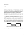
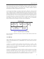
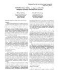
University of Twente
EEMCS / Electrical Engineering
Control Engineering
Time characteristics of PROFIBUS
on Windows XP
Yang Huang
Individual Project
Supervisors
prof.dr.ir. J. van Amerongen
dr.ir. J.F. Broenink
dipl.ing. B. Orlic, dr. H. Vos
June 2005
Report nr. 019CE2005
Control Engineering
EE-Math-CS
University of Twente
P.O. Box 217
7500 AE Enschede
The Netherlands
Huang Yang 2005
Abstract
This project is aiming to investigate the use of the PROFIBUS as a fieldbus for control
purposes, and to determine the time characteristics of PROFIBUS data transmission between
two PCs. The actual experiments are performed with PC’s running Windows XP, which is a
non-realtime OS.
The experiments are based on a one-master-one-slave PROFIBUS network with
DF-Profi2-PCI boards. Measurement results show that under Windows XP the transmission
time for a single PROFIBUS DP polling cycle is ranging from 1.9 ms to 90 ms, considering
all extreme conditions. This time is mainly dependent on the transmitted data length and the
transmission baud rate.
The conclusion is that PROFIBUS, used in combination with a non-realtime operation
system, is still a reasonable deterministic, cost-efficient and simple fieldbus, suitable for
managing I/O peripherals in the field level. However, it might not be fast enough for
high-speed real-time motion control purposes.
Further investigation of real-time performance with PROFIBUS is recommended, especially
in the combination with some real-time Operating Systems. Extending the simple network to
a larger scale network can help to get further insight into this fieldbus technology.
I
Huang Yang 2005
II
Huang Yang 2005
Table of Contents
1 Introduction .......................................................................................................................... 1
1.1 Context......................................................................................................................... 1
1.2 Assignment................................................................................................................... 2
1.3 Outline of the report..................................................................................................... 2
2 PROFIBUS Background...................................................................................................... 5
2.1 History ......................................................................................................................... 5
2.2 PROFIBUS modular structure ..................................................................................... 5
2.3 Specification ................................................................................................................ 6
2.3.1 Basics (for PROFIBUS DP/PA) ........................................................................ 6
2.3.2 Communication Layers ..................................................................................... 7
2.3.3 PROFIBUS DP Protocol ................................................................................. 12
2.3.4 GSD files ......................................................................................................... 13
3 Design Choices .................................................................................................................... 15
3.1 Introduction to LabVIEW .......................................................................................... 15
3.2 Design choice............................................................................................................. 16
3.3 Conclusion ................................................................................................................. 19
3.4 Test Design................................................................................................................. 19
3.4.1 Measurement setup structure........................................................................... 19
3.4.2 Priority and timing issues ................................................................................ 20
3.4.3 API functions of the driver .............................................................................. 21
4 Measurement and Testing .................................................................................................. 23
4.1 Measurement I ........................................................................................................... 23
4.2 Measurement II .......................................................................................................... 27
4.3 Measurement III......................................................................................................... 29
4.4 Control Loop Implementation.................................................................................... 31
4.5 Discussion.................................................................................................................. 33
5 Conclusions and Recommendations ................................................................................. 35
5.1 Conclusions................................................................................................................ 35
5.2 Recommendations...................................................................................................... 35
Appendix A............................................................................................................................. 37
Numerical values of measurement results ....................................................................... 37
References ........................................................................................................................... 41
III
Huang Yang 2005
IV
Huang Yang 2005
1 Introduction
1.1 Context
This project has two contexts.
The first one is local PhD research on CSP (Communicating Sequential Processes) based
compositional programming techniques in the context of distributed real-time systems
connected via fieldbuses*. The research deals with hard real-time control using several
co–operating processors in networked environments. The network itself is embodied by an
industrial field bus, which are investigated with respect to real-time performance.
The second context origins from the collaboration of our research group (Control
Engineering) at University of Twente in the MIC (Mechatronic Innovation Centre). Partners
of MIC are dedicated to building experimental HIL (hardware in the loop) simulation of a
plant controlled via a PLC (Programmable Logic Controller) controller. The purpose of such
a HIL simulation can be for instance rapid prototyping with testing of a system prior to
having the actual plant available. Alternatively, it can be used to test properties of the system
that, due to the associated safety risks, cannot be tested on real plant. The computer
architecture of this HIL simulation setup consists of one PLC on which the control program
is running and a PC where a simulation of the plant is running. Connection between the two
is done via a PROFIBUS connection. This architecture is in first phase further simplified by
using a PC instead of a PLC. Thus, the computer architecture that will be used in this project
consists of two PCs connected via a PROFIBUS connection. The framework of the system is
depicted in Figure 1.
PC1
(Contorller)
Figure 1
PROFIBUS
PC2
(Plant Simulation)
Framework of the experimental HIL simulation setup
In this individual project, focus is on the PROFIBUS communication and its applicability for
this kind of control systems.
* 2002-2006, Bojan Orlic, CSP-channels for field-bus-connected embedded control systems
1
Huang Yang 2005
1.2 Assignment
This individual project is focused on the real-time characteristics of the PROFIBUS fieldbus.
However, the time delay tests and measurements were performed only for of PROFIBUS DP
boards controlled by a PC running Windows XP. Still, same tests are reproducible for other,
more real-time, operating systems.
Firstly, literature study was performed in order to answer the questions what PROFIBUS is
and how communication via PROFIBUS is realized.
Then a real PROFIBUS setup was built utilizing DF-Profi2-PCI boards made by COMSOFT
GmbH, Germany. Several options existed for constructing the PROFIBUS network. After
comparison and analysis, and taking the limitations of this project into account, the decision
was made to develop an own application in C/C++ that will directly communicate to the
Windows XP board driver. Figure 2 shows the setup built in this project.
Figure 2
Framework of the setup in this project
Several tests were carried out in order to obtain time characteristics of PROFIBUS, in
Windows.
After the transmission latency measurement, a simple control loop was built. Instead of real
plant, a simulation was used and the code for both simulation and controller was generated
from a 20SIM model (http://www.20sim.com/). For the highest communication speed,
simulation results based on PROFIBUS transmission experiment are almost identical to the
results obtained in 20SIM simulator.
1.3 Outline of the report
Chapter 2 provides basic information about the PROFIBUS, including a short history, the
explanation of its modular structure and some interesting points from the specification of
PROFIBUS. Chapter 3 describes the design choices in this project. For the reader’s better
understanding of these design options, general description of LabVIEW is introduced first.
Then, the design choices are discussed with a conclusion presented. At the end of the chapter
2
Huang Yang 2005
details of designing the tests are given. Chapter 4 focuses on representation of test results
and analysis of the performed measurements. This chapter also illustrates the
implementation of a control loop and results of control loop measurements. Chapter 5 gives
conclusions as well as the recommendations on further research work.
3
Huang Yang 2005
4
Huang Yang 2005
2 PROFIBUS Background
This chapter gives an overview of PROFIBUS. Most of the knowledge and figures are
adopted from [1],[2],[3],[4].
2.1 History
The PROFIBUS (Process Fieldbus) project started in 1987 an association venture project
supported by the public authorities in Germany. Within the framework of this venture, 21
companies and institutes joined forces and created a strategic fieldbus project. The goal was
to realize and establish a bit-serial fieldbus. The basic requirement was the standardization
of the field device interface. A first step resulted in the specification of the complex
communications protocol PROFIBUS FMS (Fieldbus Message Specification), which is the
first PROFIBUS communication protocol. In 1993, a further step was the completion of the
specification for the more simply configurable and faster PROFIBUS DP (Decentralized
Periphery) protocol. As for its international standardization, PROFIBUS achieved national
standardization in 1991/1993 in DIN 19245, Part 1-3 and Europe-wide standardization in
1996 in EN 50170. Then since 1999, it was standardized in IEC61158. In 2002, the
completion of activities to update IEC61158 was established.
2.2 PROFIBUS modular structure
PROFIBUS has a modular design. Various communication technologies, application and
system profiles, as well as device management tools are available for specific requirements.
The system structure is illustrated in Figure 3 below:
Figure 3
Technical system structure of PROFIBUS
5
Huang Yang 2005
Notice that the Application Profiles I/II are user interface layers above the application layer,
which is not depicted in the graph since the popular PROFIBUS techniques do not utilize
this layer. Based on this structure, several mature PROFIBUS modules are widely used in
both factory and process automation. Figure 4 shows the best-known PROFIBUS versions.
Figure 4
Typical PROFIBUS versions
2.3 Specification
2.3.1 Basics (for PROFIBUS DP/PA)
Some basic properties of PROFIBUS DP/PA standard are summarized in Table 1.
Maximum message length
244 bytes
Data rate
9.6Kbit/s ~ 12Mbit/s*
Transmission distance
100 M @ 12 Mbit/s, 1200 M @ 9.6Kbit/s
Maximum stations/nodes without repeaters
32
Recommended maximum repeaters
4**
Arbitration method
Token Passing
Error checking
HD4, CRC
Network topology
Line, star and ring
Physical media
Twisted-pair or fiber
Communication methods
Master/slave and peer-to-peer
Table 1 Basics for PROFIBUS DP/PA
* A maximum transmission rate of 15Mbit/s can be achieved when using RS485-IS.
** Too many repeaters will cause considerable signal delay. When used, repeaters count as
stations on the bus though they do not require an address of their own.
6
Huang Yang 2005
2.3.2 Communication Layers
PROFIBUS communication is anchored in the international standards IEC 61158 and
IEC61784. In the ISO/OSI reference model, in which 7 layers have been defined in the
protocol, PROFIBUS uses layers 1, 2 and 7. (Figure 5)
Figure 5
PROFIBUS employs 3 layers from the OSI reference model
Layer 1
Layer 1, called the physical layer, defines the medium, coding and speed of the data
transmission. PROFIBUS provides four different transmission technologies: RS485,
RS485-IS, MBP and Fiber Optics, all based on international standards and associated with
PROFIBUS in both IEC 61158 and IEC 61784 standards.
RS485
RS485 is a simple, cost-effective medium. It is primarily used for tasks that require high
transmission rates, in a range between 9.6 Kbit/s and 12 Mbit/s (for RS485-IS the range is
9.6 Kbit/s to 15 Mbit/s). The maximum permissible line length depends on the transmission
rate, as defined in the system description of PROFIBUS.
RS485 supports the line topology. All devices are linked in a bus structure, which allows
addition or removal of stations or the step-by-step commissioning of the system without
influencing other stations. Up to 32 stations can be connected in a single segment. Wiring
and bus termination of RS485 is shown in Figure 6. The beginning and end of each segment
is fitted with an active bus terminator, which has a permanent power supply to ensure
error-free operation. If more than 32 stations are required, one possible way to expand the
network is utilizing repeaters to link the individual bus segments. The other, possibly simpler,
is to increase the input impedance of the transmitters, for instance, increasing the impedance
from 12 kΩ to 48 kΩ enlarges the number of stations within a segment from 32 to 128.
7
Huang Yang 2005
Different cable types (type designation A - D) for different applications are available on the
market for connecting devices either to each other or to network elements (segment couplers,
links and repeaters). When using RS485 transmission technology, PI (PROFIBUS
International) recommends the use of cable type A. Specification of cable type A is listed in
Table 2.
135 to 165 Ω
≤30 pf/m
≤110 Ω /km
Impedance
Capacity
Loop resistance
Wire diameter
Core cross-section
Table 2
>0.64mm
>0.34mm2
Specification of cable type A
RS485 works in half-duplex operation, only a single channel is available for communication.
In order to achieve synchronization, PROFIBUS adopts NRZ (Non Return to Zero).
Figure 6
Wiring and bus termination in RS485 transmission technology
RS485-IS
RS485-IS (Intrinsic Safety) is a 2-twisted-pair version, developed for strict demand of
intrinsically safe application. It will not be discussed further in this report.
MBP
MBP is synchronous transmission with a defined transmission rate of 31.25 Kbit/s. The term
MBP stands for the transmission technology with attributes “Manchester Coding” and “Bus
Powered”. This technology is frequently used in process automation as it satisfies demands
for intrinsic safety and bus power using two-wire technology.
8
Huang Yang 2005
As for topology, tree and line structures as well as the combination of the two are supported
by PROFIBUS with MBP transmission.
In practical use, MBP is usually limited to a specific segment of a plant, for instance field
devices in hazardous areas. This plant is then linked to the RS485 segment, e.g. a control
system, through a segment coupler, or links. The number of stations that can be connected to
a segment is limited to 32. However, this number can be further determined by the
protection type selected and bus power (if any).
Joint operation of bus-powered and externally fed devices is permissible. However, note that
externally fed devices also consume a basic current over the bus terminator, which must be
taken into account accordingly when calculating the maximum available feed current.
Fiber-optic
In industrial areas with high electromagnetic noise, copper based communication media may
not be able to cope with induced errors. This problem does not exist if fiber optic technique
is used. Fiber-optic is also suitable for applications where particularly large distances need to
be covered. Line, ring and star topology structures are supported with Fiber-optic
transmission.
Layer 2
Layer 2 in PROFIBUS is designated as Fieldbus Data Link (FDL). This layer is divided into
two sub layers: the Media Access Control (MAC) layer and the Logical Link Control (LLC)
layer. There are two main communications in PROFIBUS, communication between masters
and that between one master and its slave/slaves. As for MAC, methods have to be defined
to satisfy two essential requirements:
z In the case of communication between masters, all of these stations have to be given
sufficient opportunity to execute their communication tasks in a specific time interval.
z For communication between a master and its slave/slaves, data transfer should be
performed in a fast and efficient way with real-time performance guaranteed.
Consequently, MAC in PROFIBUS includes the token passing method, which ensures the
assignment of the bus access right within a precisely defined time interval with a token.
Within a pre-defined period of time, the token passing cycle time, a master in the ring will
receive the token and then be able to perform data communication. The master has to pass its
token to the next master as soon as the time allocated to it has expired.
As for communication between one master and slave/slaves, a master-slave method is
provided by MAC. PROFIBUS slaves are passive stations in the network. They can only
acknowledge received messages or transmit messages at the master’s request. PROFIBUS
9
Huang Yang 2005
master is termed active station, and only the master can access the bus and handle the
polling procedure. Within a multi-master PROFIBUS network, the masters without token are
all passive stations, and therefore can be accessed as slaves. When a master takes the token,
it is granted the right for data transmission on the bus and is able to communicate with the
slaves. A master can read data from any slave on line, but it can only write to those slaves
assigned to it.
This combined method is called the hybrid medium access. Figure 7 illustrates the
master/master and master/slave communication mentioned above.
Figure 7
A PROFIBUS DP network
The LLC layer mainly controls frame synchronization, flow control and error checking.
Based on RS485, all PROFIBUS characters are comprised of 11 bits, in which one is the
start bit, 8 data bits, one parity bit, and one stop bit. If no data is being transmitted, the idle
state potential on the data line is ‘1’. A start bit causes the data line go to ‘0’. A PROFIBUS
NRZ-coded character frame is given below.
Figure 8
A PROFIBUS character frame
In the case of MBP transmission, no start bit, parity bit and stop bit is available. That is, only
8 data bits exist within one PROFIBUS character.
10
Huang Yang 2005
Layer 2 of PROFIBUS operates connectionless. In addition to the peer-to-peer data
transmission (only in FMS and PA), broadcast and multi-cast communication is also possible
in PROFIBUS. According to IEC 61158-3, layer 2 provides the following data transmission
services to its layer above:
z
z
z
z
z
z
SDA (Send Data with Acknowledgement)
Data is sent to a master or slave with a short acknowledgement returned in response.
SDN (Send Data with No acknowledgement)
Message is sent simultaneously to a group of slaves (multi-cast), or all slaves
(broadcast), including other masters connected to the bus but without token. However,
those slaves do not respond or acknowledge this message. Broadcast is realized by
SDN.
SRD (Send and Request Data with reply)
Data is sent by a master to one of its slaves, after which the slave returns the required
data in its response (if applicable) in a pre-defined period of time. This period is also
called one telegram cycle. In regular PROFIBUS operation, cyclic data exchange
takes place between the master and its slaves by SRD.
CSRD (Cyclic Send and Request Data with reply)
Communicate in SRD way but cyclically.
MSRD (Send and Request Data with Multicast Reply)
CS (Clock time Synchronization)
The time information at the master is broadcasted to all remote stations.
Note: Not all the services are available for every PROFIBUS protocol, for instance,
PROFIBUS DP does not support the SDA. For more detail please refer to corresponding
manuals.
In addition, on layer 2 PROFIBUS also defines management related services for
initialization, configuration, event and error handling.
The main communication protocol applied in layer 2 is protocol DP, which realizes
functionalities of this layer. DP will be further introduced in section “PROFIBUS DP
Protocol”.
Layer 7
The application layer provides the communication functions to the user. Services offered by
layer 2 are executed at the interface to the LLI (Lower Layer Interface) through SAPs
(Service Access Points). Layer 7 is only defined in PROFIBUS FMS. PROFIBUS DP and
PROFIBUS PA define their own profiles as the user interfaces and do not use this layer. In
the report details on this is not presented.
11
Huang Yang 2005
2.3.3 PROFIBUS DP Protocol
Besides the first PROFIBUS protocol FMS, developed 20 years ago, in layer 2 there is a
PROFIBUS protocol named protocol DP (Decentralized Periphery), which is commonly
used as the main transmission technology in PROFIBUS. The term "Decentralized
Peripherals" stands for the simple, fast and deterministic I/O data exchange between a bus
master and its assigned slave devices.
There are two kinds of stations within a PROFIBUS DP network: DP master and DP slave.
According to IEC 61158-5, a PROFIBUS DP master can be either master class 1 or master
class 2. A master class 1 is a controlling device that controls several DP slaves (field
devices). It is usually hosted by a programmable controller or a process controller.
A master class 2 is a controlling device which manages configuration data (parameter sets)
and diagnosis data of a DP master class 1, and that additionally can perform all
communication capabilities of a DP master class 1.
Also from IEC 61158-5, a PROFIBUS DP slave is a field device that is assigned to one DP
master class 1 as a provider for cyclic I/O data exchange. In addition, acyclic functions and
alarms could be supported.
DP is now available in 3 versions, namely DP-V0, DP-V1 and DP-V2. Characteristics of
these versions are depicted in Figure 9.
Figure 9
12
Functionality of the PROFIBUS DP version with key features
Huang Yang 2005
DP-V0 specifies the basic functions of PROFIBUS transmission, including master-master’s
token passing method and master-slave’s polling data exchange. DP-V1 mainly defines the
acyclic data exchange functions of DP master class 2. DP-V2 introduces advanced
functionalities that enable communication between slaves.
As for acyclic data exchange, it can only be done between a DP class 2 master and a DP
slave. In addition, the acyclic communication takes place when all the slaves of DP class 1
master are polled and there is still time left until next polling cycle. The DP class 2 master
can take the token and is able to access the slaves acyclically after all the DP class-1 masters
have used up their time. As soon as the next polling starts, the acyclic communication has to
stop and the token has to be passed to the first DP class 1 master. In other words, the acyclic
data exchange can only fill in the time gaps of every polling cycle. As an introduction,
Figure 10 illustrates how DP manages cyclic and acyclic communication.
TIME LINE
Polling
Slave1
...
Polling
Slave2
Polling
Slave1
used by
DP class 1 masters
Acyclic
Communication
Polling
Slave1
...
used by
DP class 2
masters
one polling cycle
Figure 10
Sequential diagram for DP polling
Due to the limitation of hardware in the project, only DP-V0 will be further discussed in the
following chapters.
2.3.4 GSD files
GSD (an abbreviation for the German term "Gerätestammdaten") files are device specific
database files for PROFIBUS devices. All PROFIBUS class 1 masters and slaves have their
own GSD files.
A GSD file is an ASCII text file containing device-specific data, for instance, vendor
identification information, supported baud rates, number of input/output data, meaning of
diagnostic messages, data formats etc. Many PROFIBUS configuration tools are available to
edit, check and use the GSD files.
The master of a PROFIBUS network utilizes GSD files to build its parameter record. When
initializing a PROFIBUS network, the master imports necessary parameters of each station
of the network from the GSD files before configuration starts. In this way, plug & play
interoperability among different devices from different manufacturers is realized.
13
Huang Yang 2005
Details and format of a standard GSD file are specified in EN50170 standard and
PROFIBUS Guideline 2.041
14
Huang Yang 2005
3 Design Choices
In this chapter design choices in this project are discussed. Since LabVIEW and its real-time
module is one of the options being discussed, first a brief description on LabVIEW is given.
[5]
3.1 Introduction to LabVIEW
LabVIEW is a graphical development environment developed by National Instruments
(http://www.ni.com/labview/). Applications created by LabVIEW are widely used in the
fields of testing, measurement and control engineering.
In LabVIEW, the block called VI (Virtual Instrument), takes the place of function compared
to general-purpose programming languages. Functions can be called by other functions, and
similarly VIs can be encapsulated and reused by other VIs. Data flow determines the
execution of applications in LabVIEW environment. A VI will not function until all its input
data is ready.
There are generally two parts for a VI, the front panel and the block diagram (Figure 11).
The front panel offers a friendly graphical user interface, for instance, buttons, waveforms
and LED lights. Behind the front panel, the block diagram containing LabVIEW source
code defines the functionality of the VI. A VI functionality can be exported to an executable
file and be executed on any PC with the LabVIEW environment installed. Further more the
block diagrams of a VI can be protected by a password to keep the contents secret, while this
VI can still be used via the front panel by the end user.
Figure 11
Front panel and block diagram
15
Huang Yang 2005
National Instruments LabVIEW RT (Real-Time) Module extends the LabVIEW
development environment to deliver deterministic real-time performance. LabVIEW RT
supports two kinds of real-time platforms, RTX (Real-Time Extension) and ETS (Embedded
Tool Suite). These platforms are also called RT targets.
The first one, RTX, adds a real-time subsystem (RTSS) to Windows such that LabVIEW RT
applications can execute on computers. The deterministic real-time behavior of applications
running on RTSS is not affected by performance of Windows, because the subsystem runs in
parallel with Windows and its scheduling supersedes Windows scheduling.
The latter, ETS, needs NI RT series hardware to work on. It provides for the hardware a
real-time operating system, on which the LabVIEW RT applications can be executed. Once
downloaded to the hardware, the embedded program can run without disrupting even when
the host computer is entirely shut down.
3.2 Design choice
In the project, three options are available to build a PROFIBUS network.
1. Using LabVIEW RT ETS version and a PXI hardware
In this approach, two DF-Profi2-CPCI (Compact PCI) boards should be first mounted into a
PXI (PXI-1031, for instance) device as a PROFIBUS module, and each PXI device can be
connected to a separate PC. After configuring one board into master and the other slave, the
LabVIEW RT application and a PROFIBUS network configuration file are downloaded onto
the master CPCI board. The PXI devices can be accessed by their unique IP address. After
rebooting the hardware, the application downloaded to the PXI device will start, initialize
the network, do transmission and measurement, and finally send back required data to the
host computer.
Note: PXI (PCI eXtensions for Instrumentation) is a rugged PC-based platform for
measurement and automation systems.
Pros and cons:
It is a common way utilizing LabVIEW RT to build a PROFIBUS network. The PC-based
architecture and advanced synchronization features of the PXI modular instrument promise a
high performance in real-time tasks.
An obvious problem of doing test in this way is the encapsulation of VIs offered by the
company who provides the boards. Protected by passwords, these VIs are black boxes to the
end users. This means that it is hardly possible to measure time delay of a certain part of the
whole transmission, for instance, time delay of those parts within “Process Data” before the
transmission starts. As shown in Figure 12, time spent in section A of the
DFP2_TransferProcessData.vi does not belong to the measured transmission delay.
16
Huang Yang 2005
Figure 12
Data flow through a VI
The black-box approach does not give enough insight in the way things work and is
therefore not especially interesting for future subprojects of the parent PhD project.
On the other hand, it is required to purchase extra hardware, the PXI devices, for this
approach. However, the cheapest PXI product made by National Instrument, PXI-1031
already cost more than €1000. For our case, such hardware is out of the budget of the
individual project. In addition, for this method the PCI boards should be replaced with CPCI
boards.
Note: Configuration tool of the board currently does not support LabVIEW RT RTX version.
2. Developing own application in C/C++
Own application development is available under Windows by directly accessing the API
provided by the driver of the board. A general process for using the board as a master or a
slave with the driver is depicted in Figure 13.
Pros and cons:
Apparently writing own programs in the lower level might take more time to implement the
desired tests. More detailed knowledge about the PROFIBUS protocol is necessary in order
to do application development without an advanced development environment like
LabVIEW RT. However, demo codes supplied with the board driver will definitely shorten
the development period sharply, since it is possible to construct our own application by
easily reusing functions of the demos instead of starting programming from scratch.
Doing test in C/C++ way gets closer to the need of the associated PhD project. With more
specific knowledge of PROFIBUS, measurement result can be obtained and explained in a
more transparent and logical way.
On the other hand, the research group is now working on Debian Linux patched with RTAI.
COMSOFT, the producer of the board used here does not support this real-time system.
QNX, a real-time operating system that is supported by the board manufacturers, becomes
an impractical choice in this project, because too much time would be spent on studying this
OS. Thus, Windows becomes the only choice if this option is chosen. Besides, since the
operating system here does not satisfy the real-time demands, it is hardly possible to
measure the real-time characteristics of PROFIBUS.
17
Huang Yang 2005
Figure 13
Process of using the DF-Profi2-PCI board as a PROFIBUS
t ti
18
Huang Yang 2005
3. Using LabVIEW for Windows
LabVIEW for Windows does not guarantee a real-time performance. Also the contents of
VIs supplied by COMSOFT are password protected. With this option, neither real-time
performance nor a further look inside the PROFIBUS protocol is possible.
3.3 Conclusion
After careful comparison among these choices, finally it was decided to develop our own
C/C++ application with a Windows driver. Since the Windows operating system itself is not
a real-time platform, time characteristics obtained by measurements are not expected to be
deterministic. For the sake of measurement accuracy, the method for timing in Windows is
essential. All these have been taken into account to make measurement and make tests
performed on Windows XP as close as possible to a realtime operating system measurement.
Details of the measurement and test will be shown in the next chapter.
3.4 Test Design
3.4.1 Measurement setup structure
As mentioned before, DP utilizes polling to realize master/slave communication. In our case,
the Windows driver of the board handles the whole polling procedure. The polling starts as
soon as the board is set to be a master and activated. A user application can write and read
the board’s memory via the provided API functions. In every polling cycle, the driver of the
master will send command to the slave. A command can be either sending data to a slave,
requiring data from a slave or both. In such a way, user data in both memory of master and
slave will be updated after a single polling.
User Application
(Slave)
User Application
(Master)
User Interface
Board Memory
Board Memory
FDL
(Board Driver)
BUS
Physical Layer
Communication
handled by API functions
Figure 14
Communication
handled by Board driver
PROFIBUS DP communication data flow
19
Huang Yang 2005
As illustrated in Figure 14, Layer 2 (FDL) is handled by the board driver. Above Layer 2,
some API functions are available in the User Interface for user to access the memory of
boards.
3.4.2 Priority and timing issues
Considering the operating system we choose in this project is not a realtime operating
system, the process and thread of timing and communication may be interfered by other
processes or threads. In order to obtain the measurement data as accurate as possible, the
corresponding process and thread are set to the highest priority. In Windows the highest
priority for a process and a thread are REAL_TIME_PRIORITY_CLASS and
THREAD_PRIORITY_TIME_CRITICAL separately.
A process of REAL_TIME_PRIORITY_CLASS has the highest possible priority. The
threads of the process preempt the threads of all other processes, including operating system
processes performing important tasks. For example, a real-time process that executes for
more than a very brief interval can cause disk caches not to flush or cause the mouse to be
unresponsive. In this way, the measurement process is protected from being interrupted by
most processes. Stable and reliable measurement results can be obtained.
A template is shown below that can be used to set the measurement process and thread to the
highest priority.
SetPriorityClass(GetCurrentProcess(),REALTIME_PRIORITY_CLASS);
SetThreadPriority(GetCurrentThread(),THREAD_PRIORITY_TIME_CRITICAL);
// measurement done here
SetThreadPriority(GetCurrentThread(),THREAD_PRIORITY_NORMAL);
SetPriorityClass(GetCurrentProcess,NORMAL_PRIORITY_CLASS);
Code 1
Template for Setting Priority
PROFIBUS DP offers the time stamp profile, which is used for precise time assignment.
However, the precision of this time stamp is only one ms, which is a too long time-period for
the measurement. Many Windows functions are available for timing, but most of them are
not suitable in this project. They returns the number of ms or even seconds that have elapsed
since the system was started.
For those processors with a high-resolution performance counter, two API functions are
available
in
Windows,
namely
QueryPerformanceFrequency
and
QueryPerformanceCounter. [6]
The declaration signatures of these two functions are listed in Code 2:
20
Huang Yang 2005
BOOL QueryPerformanceFrequency( LARGE_INTEGER *lpFrequency );
BOOL QueryPerformanceCounter( LARGE_INTEGER *lpPerformanceCount );
Code 2
Syntaxes of Timing Functions
With QueryPerformanceFrequency, the frequency of the high performance counter is
obtained. Further, QueryPerformanceCounter gives the current performance counter value.
With the counter frequency and two counter values at the start and the end-point of time, the
time elapsed in a certain period of time can be obtained, in ms, by the following calculation:
nElapsed = (int)(((CountEnd.QuadPart-CountStart.QuadPart)*1000000)/Fre.QuadPart)
where CountEnd and CountStart are of type LARGE INTEGER and contain the counter
values, Fre is also of type LARGE INTEGER and provides the frequency of the counter,
nElapsed stores the time elapsed in ms.
With this method, depending on the chosen platform the accuracy of measurement up to
1 µ s can be achieved.
Figure 15 depicts the general procedure of measurements in this project. Note that the
Read/Write block represents the process to be timed in different measurements.
Set Priority
Start Timing
Figure 15
Read/Write
Stop Timing
Reset
Priority
Procedure of Measurement
3.4.3 API functions of the driver
The Windows driver of the board provides API functions for initialization, parameterization,
diagnose and communication purposes. For a better understanding of the measurements
presented in the next chapter, the functions for master/slave communication will be
introduced in this report. For more detail of development with the board driver please refer
to the user manual. [7]
GET_DP_POLL_DATA: This function reads the actual process image from the memory on
the board. The process image contains the slaves’ output data, status and time stamp as well.
Data in the process image is updated after polling every time.
PUT_DP_POLL_DATA: This function puts the output commands for slaves to the memory
on the board. The commands will be sent to slaves in the next polling cycle.
21
Huang Yang 2005
GET_PUT_DP_POLL_DATA: This is the combination of the first two functions, but is the
fastest and most efficient way to exchange data with DP slaves. The advantage of using this
function will be shown by later measurement.
DFP2_PUT_GET_SLV_DATA: This is the only function available for a slave to prepare
response data and read commands of the master from the memory on the board. In addition,
the slave status and timestamp can be obtained with this function.
22
Huang Yang 2005
4 Measurement and Testing
In the performed experiments, 2 PCs were used.
Settings of the first PC are:
Pentium IV 2530MHz
512 MB Memory
Windows XP
Settings of the second PC are:
Pentium II 400MHz
128 MB Memory
Windows XP
The most significant aspect affecting the time characteristic is the length of transmitted data
and baud rate. For the DF-Profi2-PCI, length of either input or output data can be set to 4
bits, 8 bits, 16 bits, 32 bits, 64 bits, 128 bits, 192 bits or 240 bits. A DF-Profi2-PCI board
supports an input/output pattern with any combination of the above data length. Baud rates
applicable for RS-485 cabling supported by the board are in the range from 9.6kbps to
12Mbps. Measurement were performed by changing the transmitted data length and baud
rate. Besides Measurement II, results in other measurements are provided in the form of
mean and variance of 1000 samples. If not specified, the baud rate set in the measurements
is 12Mbps.
4.1 Measurement I
The first measurement was done in order to find out how much time is spent on the User
Interface in data transmission. That is, the time elapsed in reading and writing the board
memory.
In the measurement, one of the following functions will be timed, namely
GET_DP_POLL_DATA, PUT_DP_POLL_DATA and GET_PUT_DP_POLL_DATA.
Note that the API functions do not access the bus. Instead, they read or write to memory of
the board. The functions check if there is new data available in the memory or not. If there is
new data, they copy the data. Otherwise, they return immediately without data operation.
This can be shown in Figure 16. In the figure, peaks appear cyclically indicating data in the
memory is updated and the function copies data, which will take time. The rest samples with
a correspondingly smaller value mean that at that moment, there is no new data available,
then no data copy is necessary. The function does nothing but return directly. Hence, less
time costs in this case. Due to some unpreventable interrupts from other processes, peak
values vary from one to another.
23
Huang Yang 2005
Figure 16
Time elapsed in 1000 measurement samples
The following graphs show the measurement results on the time elapsed of these functions.
Note that in the graphs the number on I/O bytes axis indicates both the input and output data
length, for instance, 4 means the length of input data is 4 bytes and that of output data is also
4 bytes. Average time and Average Standard Deviation is the mean value and standard
deviation of time elapsed in all the samples. Action Time and Standard Deviation of Action
has the same meaning but is obtained from those samples in which the function really copies
data. Idle Time and Standard Deviation of Idle give the mean and standard deviation of those
samples in which the function does not copy data but return.
Figure 17-a
24
Huang Yang 2005
Figure 17-b
Figure 18-a
Figure 18-b
25
Huang Yang 2005
Figure 19-a
Figure 19-b
By comparing different curves within one figure, it is obvious that a function call cost very
little time when no new data is available. In practical application, where continuous
assessment to the memory is always necessary, this feature makes the communication much
more time-efficient.
Both GET_PUT_DP_POLL_DATA and GET_DP_POLL_DATA will cost more time when
more user data is transmitted, while time elapsed with PUT_DP_POLL_DATA remains a
more or less stable value even when user data length increases. It can also be seen that GET_PUT_DP_POLL_DATA takes about the same time as GET_DP_POLL_DATA does. A
conclusion can be made that reading is the most time consuming operation when accessing
the board memory.
In the situation that both reading and writing with memory of the board is required, it is
recommended to use GET_PUT_DP_POLL_DATA instead of the combination of
26
Huang Yang 2005
GET_DP_POLL_DATA and PUT_DP_POLL_DATA.
In the slave board, only one function is provided for reading and writing the board memory:
DFP2_PUT_GET_SLV_DATA. Time elapsed with this function call is depicted below.
Similar with GET_PUT_DP_POLL_DATA, more user data indicates longer delay with
DFP2_PUT_GET_SLV_DATA.
Figure 20-a
Figure 20-b
4.2 Measurement II
Since PROFIBUS DP communication is based on polling, the time of a single polling cycle
can be measured by one-way transmission. That is, the master keeps sending changing data
to its slave at regular intervals and the slave store the data in its input buffer at a very high
frequency. The frequency is sufficiently high that data transmitted from the master in every
polling cycle can be stored in the slave. Then by changing the value of master sending
interval, a minimum can be found such that the slave can still catch every data transmitted
27
Huang Yang 2005
from the master. This minimum is the polling cycle time. A block below illustrates the whole
measurement procedure.
Store i
Delay_S
Send i
PROFIBUS
Receive i
Delay_R
i++
Receiver Loop (slave)
Sender Loop (master)
Figure 21
Procedure of Measurement II
Two factors, data length and baud rate, are taken into account here. First, the baud rate is
fixed to 12Mbps and data length is changed. This measurement result is shown in Figure 22.
The second measurement is done with changing baud rate and fixed transmitted data length,
the result of which is depicted in Figure 23.
Figure 22
Figure 23
28
Huang Yang 2005
Measurement result of Cycle Time I reveals that time elapsed within a single polling is less
than 2 ms (to be specific, 1900 µ s ) unless a data length of more than 64 is chosen. That is
because at a certain transmission rate (12Mbit/s in this case) a limited length of data can be
sent within a single polling cycle. When more user data is to be transmitted extra
transmission time is required.
The theory applies in Cycle Time II as well, in which the cycle time decreases sharply with
the transmission baud rate increases. It is measured that the cycle time comes to a constant
value after the baud rate is sufficiently high. Further increasing the baud rate will not
improve the cycle time because the bottleneck is for high baud rates situated in a driver
performance. Again, the minimum cycle time in the measurement is 1900 µ s .
This result has revealed that PROFIBUS is only deterministic at a fixed maximum data
length. If the number of slaves or the data length transmitted with a slave increases and the
total transmitted data length exceed the maximum, the PROFIBUS transmission time will
increase incredible. The term deterministic of PROFIBUS also indicates that once the data
length is known the transmission time is predictable.
Note that the time measured during a single cycle mainly includes time elapsed for the
following activities happened during transmission:
z Time for the profibus chip to send the DataExchangeRequest to the slave
z The time for the slave to answer and send the data
z The time for the profibus chip copies the data to its memory
z The time the Arbitrating processors offers the new data to the windows driver, that is, to
copy data from memory of the board
z The time for the slave to copy its received data to the output buffer
4.3 Measurement III
Another method to examine the time characteristics is to utilize a roundtrip. That is, to send
a piece of data from the master to a slave and receive response from the slave to the master.
The elapsed interval is the time latency of a single PROFIBUS roundtrip.
Only the master of PROFIBUS can access the bus and manage the whole process of
communication. Then we do timing in the master application. The services of PROFIBUS
DP, GET_PUT_DP_POLL_DATA, in master board and DFP2_PUT_GET_SLV_DATA in
slave are again used in this measurement. Note the time at the start and end of the service,
and the roundtrip time is the difference between these two measurements. The whole
procedure is depicted in Figure 24.
29
Huang Yang 2005
Start Timing
Send Data
Receive Data
Roundtrip Time
Receive Data
StopTiming
Copy Data
PROFIBUS
Send Data
Master
Figure 24
Slave
Procedure of Measurement III
The Measurement results are shown in the Figure 25.
It can be found out that when the user data length is shorter than 128 the roundtrip time is a
fixed value about 6 ms. In the case of longer data length needs to be transmitted, the
roundtrip time increases noticeably, which is coincided with the conclusion of Measurement
II.
Figure 25
Although a single polling cycle time is T, it takes 3T to complete a roundtrip. This is
illustrated in Figure 26. As soon as the master sends data to the slave and the first polling
cycle finishes, the next polling starts and data stored in the slave memory is fetched to
master immediately. Within this period of time the slave has not yet finished data processing,
including copying data from its input buffer to the output buffer. Another factor for the delay
is that for slave a minimum interval has to be inserted between two successive memory
operations. Then the master can only receive the slave’s updated response after the third
polling finishes.
30
Huang Yang 2005
Figure 26
Sequence diagram of a roundtrip
4.4 Control Loop Implementation
In order to test the performance of PROFIBUS DP from the control-engineering point of
view, a distributed control loop is deployed. The control loop implementation is an
application of the previous measurement results as well.
Based on the PROFIBUS DP connection, a distributed simulation of the plant and associated
controller are implemented. Both plant and controller are modeled in 20SIM tool. The plant
is a simple DC motor known as Linix.
The 20SIM model is shown in Figure 27. Controller takes in the sampled signal from a set
point generator and feedback from the Linix Plant as well. After zero-order- hold the output
steering signal of Controller is then sent to the Linix Plant. Based on this simple feedback
loop, the output of the Plant will follow the set point signal.
Figure 27
20SIM model
Figure 28 displays the simulation result in 20SIM simulator with a sample frequency of 1
KHz.
31
Huang Yang 2005
Figure 28
20SIM Simulation
Utilizing the C Code Generation tool of 20SIM, Controller and Linix plant in the control
loop are implemented into the application of PROFIBUS master and slave separately. In
realization, the Controller is deployed on the PROFIBUS master application, while Linix
Plant is deployed on the slave application. Since the steering and feedback signal is sent
between intervals, it is not necessary to implement the ZOH and Samplers.
Within both the Controller and Linix plant there is a while loop, which repeats the
calculation of input and output signals. Euler integration method is utilized in the Linix plant
to simulate the continuous performance. The two models, namely Controller and Linix plant,
are running in two different PC separately. In case models are recalculated continuously
without inserted time delays, speed difference between these two PCs will affect the
simulation seriously. To prevent that a delay time is inserted into the loop of both models.
Necessary intervals for PROFIBUS communication limit the minimal value of the delay
time.
From the PROFIBUS transmission point of view, the baud rate is set to 12Mbps and
transmitted data length is 8 bits output and 8 bits input. Then the minimum of interval,
between which a steering signal or a feedback signal is sent, should be 1900 µ s , according
to the result of Measurement II.
When delay time of the Controller, the interval, is set to 1000 µ s , we obtain an output of the
Linix Plant shown in Figure 29. It can be seen that the output is not stable and there is
obvious difference between the simulation and that in 20SIM simulator. That is because
some of the control and feedback signal is missing due to the too small interval value.
32
Huang Yang 2005
Figure 29
Simulation based on PROFIBUS connection (with 1 ms interval)
When the delay time is set to 1900 µ s , a perfect following is achieved, which is shown in
Figure 30.
Figure 30
Simulation based on PROFIBUS connection (with 1.9ms interval)
4.5 Discussion
With the Windows driver, a single polling cycle time in PROFIBUS with a DF-Profi2-PCI
master and a DF-Profi2-PCI slave is around 1.9 ms when transmitted user data length is
equal or less than 64 bytes. This value will increase noticeably with more user data, for the
extreme case, a data transfer of 240 bytes output and 240 bytes input data will require a
33
Huang Yang 2005
cycle time of 2.5 ms. (Measurement II)
The time cost in accessing the memory on the board should also be taken into account when
considering the time factor. For the master one read-and-write to the memory will take a
period of time ranging from 115 µ s to 220 µ s , depending on the length of user data
exchanged. For the slave, this value is from about 500 µ s to 580 µ s . (Measurement I)
To do roundtrip within a single polling cycle is hardly possible. The reason is that the slave
has its own minimum operation interval and it needs some extra time to process receive data.
From the performed experiments conclusion can be drawn that 3 times of polling cycle time
are required to complete a roundtrip. (Measurement III)
Control based on PROFIBUS DP is possible. A transmitted data of no more than 64 bytes
with a baud rate of 12Mbps can achieve a fastest transmission rate. For a digital control
system, the maximum sample rate can achieve 526 Hz based on PROFIBUS DP
transmission.
Considering the fact that Windows XP is not a real-time operating system, measurement
could be interrupted by other processes. Thus in the measurements, timing cannot achieve to
the accuracy of 1 µ s and there is inevitable deviations in the measurements(standard
deviations are less than 100 µ s in Measurement I, and less than 300 µ s in Measurement
III).
At the end of the project, beta version of the board’s Windows driver is available and some
tests are done based on this new driver. Measurement shows that the roundtrip time is
around 3200 µ s at the baud rate of 12Mbps with transmitted data length ranging from 4
bytes input/ 4 bytes output to 240 bytes input/ 240 bytes output. This indicates that with the
new driver, the transmission speed is about 2 times faster. However, more measurement is
necessary to obtain a complete conclusion, which is also recommended in the last chapter of
this report.
34
Huang Yang 2005
5 Conclusions and Recommendations
The conclusion and recommendation below only applies to study and application of
PROFIBUS DP with Windows driver.
5.1 Conclusions
PROFIBUS DP is suitable in management of field devices like sensors and I/O devices etc.
Its open standard makes it convenient and safe to add or delete a device to/from the network.
The simple, fast and deterministic way of data exchange in PROFIBUS fits the requirement
of communication in field level of a system.
PROFIBUS supports a wide range of transmission technology, including RS485, MBP and
optical fiber. This feature reduces the cost PROFIBUS network and increases its
compatibility as well.
PROFIBUS DP cannot satisfy the requirement of high-speed real-time motion control,
which needs data transmission delay within scores of µ s . Since in the case of PROFIBUS
communication, it is necessary to have a transmission interval of around 1.9ms.
PROFIBUS exchanges a maximum data of 480 bytes in a single cycle, that is, 240 bytes
output and 240 bytes input for a master. It is not recommended to utilize PROFIBUS in the
situation where huge amount of data needs to be transferred in a short period of time.
5.2 Recommendations
To realize a PROFIBUS network with a faster board driver and complete the measurements.
To investigate the realtime performance of PROFIBUS based on a realtime OS.
To build a multi-master and multi-slave PROFIBUS network and then check its
performance.
35
Huang Yang 2005
36
Huang Yang 2005
Appendix A
Numerical values of measurement results
Average Time Elapsed of
GET_PUT_DP_POLL_DATA (12Mbps)
I/O bytes Mean
4
75
8
76
16
79
32
85
64
94
128
115
240
151
Standard Deviation
10
10
10
11
11
11
13
Action Time Elapsed of
GET_PUT_DP_POLL_DATA (12Mbps)
I/O bytes
4
8
16
32
64
128
240
Mean
116
117
116
129
141
165
220
Standard Deviation
13
13
15
16
15
14
16
Idle Time Elapsed of
GET_PUT_DP_POLL_DATA (12Mbps)
I/O bytes
4
8
16
32
64
128
240
Mean
24
24
25
24
25
25
25
Standard Deviation
4
2
5
3
4
3
1
Average Time Elapsed of
DFP2_PUT_GET_SLV_DATA (12Mbps)
I/O bytes Mean Standard Deviation
4
33
79
8
35
80
16
39
84
32
46
87
64
62
98
128
91
108
240
144
118
Action Time Elapsed of
DFP2_PUT_GET_SLV_DATA (12Mbps)
I/O bytes
4
8
16
32
64
128
240
Mean Standard Deviation
497
47
487
17
499
44
503
21
521
56
537
38
582
44
Idle Time Elapsed of
DFP2_PUT_GET_SLV_DATA (12Mbps)
I/O bytes
4
8
16
32
64
128
240
Mean Standard Deviation
19
1
21
4
24
2
29
2
41
5
65
8
113
5
37
Huang Yang 2005
Average Time Elapsed of
GET_DP_POLL_DATA (12Mbps)
I/O bytes
4
8
16
32
64
128
240
Mean
76
77
80
85
95
116
152
Standard Deviation
11
11
11
12
11
12
15
Action Time Elapsed of
GET_DP_POLL_DATA (12Mbps)
I/O bytes
4
8
16
32
64
128
240
Mean
118
115
119
128
144
169
208
Standard Deviation
10
12
12
14
14
17
16
Idle Time Elapsed of
GET_DP_POLL_DATA (12Mbps)
I/O bytes
4
8
16
32
64
128
240
38
Mean
25
25
25
24
24
24
24
Standard Deviation
5
6
3
4
4
6
2
Average Time Elapsed of
PUT_DP_POLL_DATA (12Mbps)
I/O bytes
4
8
16
32
64
128
240
Mean
20
21
21
20
20
21
21
Standard Deviation
14
9
10
9
10
11
13
Action Time Elapsed of
PUT_DP_POLL_DATA (12Mbps)
I/O bytes
4
8
16
32
64
128
240
Mean
63
72
71
70
74
83
89
Standard Deviation
8
6
7
8
9
11
10
Idle Time Elapsed of
PUT_DP_POLL_DATA (12Mbps)
I/O bytes
4
8
16
32
64
128
240
Mean
12
12
12
12
12
12
12
Standard Deviation
1
2
1
2
1
3
2
Huang Yang 2005
Cycle Time I (12Mbps)
Cycle Time II
(8 input bytes/ 8 output bytes)
I/O bytes Cycle Time
4
1900
8
1900
16
1900
32
1900
64
1900
128
2400
240
2500
Baud rate
9.6k
93.75k
1.5M
3M
6M
12M
Cycle Time
90000
7000
2300
2100
1900
1900
Roundtrip Time (12Mbps)
I/O bytes
4
8
16
32
64
128
240
Mean
5922
5916
5926
5941
6105
7222
8146
Standard Deviation
163
207
170
201
298
301
221
Time Unit:
µs
39
Huang Yang 2005
40
Huang Yang 2005
References
[1] PI (2005), “PROFIBUS Glossary”, www.profibus.com
[2] PI (2005), “PROFIBUS Overview”, www.profibus.com
[3] PI (2002), “PROFIBUS Technology an Application – System Description”,
www.profibus.com
[4] ACROMAG Inc. U.S.A (2005), “Introduction to PROFIBUS DP”
[5] LabVIEW (2005), “LabVIEW Real-Time Module User Manual”,
http://www.ni.com/labview/
[6] Johan Nilsson (2005), “Implement a Continuously Updating, High-Resolution Time
Provider for Windows”
[7] COMSOFT Germany (2005), “PROFIBUS-DP/DPV1 Protocol Driver”,
41