1
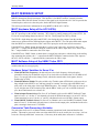
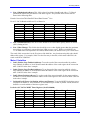
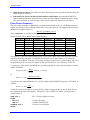
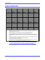
^1 USER MANUAL
^2 Accessory 24C2A
^3 Compact UBUS 4-Axis Analog Servo Card
^4 4Ax-603611-xUxx
^5 October 15, 2003
Single Source Machine Control
Power // Flexibility // Ease of Use
21314 Lassen Street Chatsworth, CA 91311 // Tel. (818) 998-2095 Fax. (818) 998-7807 // www.deltatau.com
Copyright Information
© 2003 Delta Tau Data Systems, Inc. All rights reserved.
This document is furnished for the customers of Delta Tau Data Systems, Inc. Other uses are
unauthorized without written permission of Delta Tau Data Systems, Inc. Information contained
in this manual may be updated from time-to-time due to product improvements, etc., and may not
conform in every respect to former issues.
To report errors or inconsistencies, call or email:
Delta Tau Data Systems, Inc. Technical Support
Phone: (818) 717-5656
Fax: (818) 998-7807
Email: [email protected]
Website: http://www.deltatau.com
Operating Conditions
All Delta Tau Data Systems, Inc. motion controller products, accessories, and amplifiers contain
static sensitive components that can be damaged by incorrect handling. When installing or
handling Delta Tau Data Systems, Inc. products, avoid contact with highly insulated materials.
Only qualified personnel should be allowed to handle this equipment.
In the case of industrial applications, we expect our products to be protected from hazardous or
conductive materials and/or environments that could cause harm to the controller by damaging
components or causing electrical shorts. When our products are used in an industrial
environment, install them into an industrial electrical cabinet or industrial PC to protect them
from excessive or corrosive moisture, abnormal ambient temperatures, and conductive materials.
If Delta Tau Data Systems, Inc. products are directly exposed to hazardous or conductive
materials and/or environments, we cannot guarantee their operation.
Accessory 24C2A
Table of Contents
INTRODUCTION .......................................................................................................................................................1
Overview ...................................................................................................................................................................1
Features .....................................................................................................................................................................1
Board Configuration..................................................................................................................................................2
ACC-24C2A Power Supply Requirements ...............................................................................................................2
BOARD LAYOUT.......................................................................................................................................................3
E-POINT JUMPER SETTINGS ................................................................................................................................5
ACC-24C2A (Channels* 1, 2, 3, 4) ..........................................................................................................................5
HARDWARE SETUP .................................................................................................................................................7
Switch Configuration ................................................................................................................................................7
UMAC Turbo CPCI Address DIP Switch S1 ........................................................................................................7
ACC-24C2A Clock Settings .....................................................................................................................................7
UMAC CPCI Clock Setup for ACC-24C2A ..........................................................................................................7
UMAC MACRO CPCI Clock Setup for ACC-24C2A ...........................................................................................7
Resistor Pack Configuration......................................................................................................................................7
Termination Resistors Packs ................................................................................................................................7
Encoder Loss Resistor Packs................................................................................................................................8
Limit/Flag Voltage Level Resistor Packs..............................................................................................................8
Opto-Isolation Considerations...................................................................................................................................9
Limit/Flag Circuit....................................................................................................................................................10
Connecting Limits/Flags to the ACC-24C2A......................................................................................................11
Amplifier Fault Circuit............................................................................................................................................11
Loss of Encoder Circuit...........................................................................................................................................12
Position Compare Port Driver IC ............................................................................................................................13
UMAC TURBO CPCI SOFTWARE SETUP .........................................................................................................15
Servo IC Configuration I-Variables ........................................................................................................................15
Servo IC Numbering ...........................................................................................................................................15
Servo Channel Numbering..................................................................................................................................15
Multi-Channel I-Variables..................................................................................................................................15
Single-Channel I-Variables ................................................................................................................................16
Encoder Conversion Table I-Variables ..............................................................................................................17
Motor Addressing I-Variables ............................................................................................................................17
UMAC Turbo CPCI Example Setups......................................................................................................................21
MLDT FEEDBACK SETUP ....................................................................................................................................23
MLDT Hardware Setup of the ACC-24C2A...........................................................................................................23
MLDT Software Setup of the UMAC Turbo CPCI.................................................................................................23
Hardware Setup I-Variables for Servo IC m ......................................................................................................23
Conversion Table Processing I-Variables ..........................................................................................................23
Motor I-Variables ...............................................................................................................................................24
Pulse Output Frequency .....................................................................................................................................25
12-BIT ADC OPTION...............................................................................................................................................27
PINOUT DESCRIPTION .........................................................................................................................................29
Table of Contents
i
Accessory 24C2A
ii
Table of Contents
Accessory 24C2A
INTRODUCTION
Overview
The ACC-24C2A Axis Expansion Board is a single-slot module providing the interface circuitry for 4
axes, either analog interface for torque or velocity mode amplifiers or pulse and direction output for
stepper motor drives. It has a ‘slave’ Compact-UBUS interface on its J1 connector and the servo interface
signals are on the J2 connector. Opto isolation is maintained between the analog circuitry and the digital
circuitry to isolate the main axis flags.
The ACC-24C2A is part of the CPCI family of expansion cards and these accessory cards are designed to
plug into an industrial CPCI rack system. The information from these accessories is passed directly to
either the UMAC Turbo CPCI CPU via the high speed Compact UBUS. Other Compact UBUS interface
cards include the following:
•
•
•
•
•
ACC-11C General purpose 96-point I/O card with short circuit protection
Up to eight ACC-24C2A boards can be connected to one UMAC Turbo CPCI system, providing up
to 32 additional channels of servo interface circuitry. The ACC-24C2A board contains no processor;
it has 1 highly integrated 4-channel PMAC2-style “Servo IC” with the buffering circuitry and
connectors around them. Some new features added to the family of ACC-24C2A breakout boards
include:
Loss of encoder circuit
5V to 24V Flag inputs
Pulse and direction outputs for stepper systems or MLDTs
12-bit ADC option
Features
The ACC-24C2A board can be used with any UMAC Turbo CPCI, interfacing through the Compact
UBUS.
The ACC-24C2A supports a wide variety of servo and stepper interfaces:
•
•
•
•
•
Analog +/-10V velocity commands
Analog +/-10V torque commands
Sinusoidal analog +/-10V phase current commands
Pulse-and-direction commands
Eight 12-bit ADC inputs
Introduction
1
Accessory 24C2A
Board Configuration
An ACC-24C2A comes standard with one Servo IC providing four servo interface channels, which are
brought out on the P2 connectors on the ‘backside’ of the Compact UBUS backplane board. Each channel
of servo interface circuitry includes the following:
•
•
•
•
•
Two output command signal sets, configurable as either:
1 pulse-and-direction
2 DAC outputs
Three-channel differential/single-ended encoder input
Sixteen input flags, 4 Amplifier enable outputs
ACC-24C2A Power Supply Requirements
The following table lists the power requirements for the ACC-24C2A.
2
Product
5V
12V
for DACs
-12V
for DACs
ACC-24C2A
1000mA
400mA
400mA
Introduction
Accessory 24C2A
BOARD LAYOUT
Board Layout
3
Accessory 24C2A
4
Board Layout
Accessory 24C2A
E-POINT JUMPER SETTINGS
ACC-24C2A (Channels* 1, 2, 3, 4)
Jumper
Config.
E1
1-2-3
Description
Default
Jump 1-2 for UMAC MACRO CPCI (receive servo
Factory set
and phase clock)
Jump 2-3 for UMAC Turbo CPCI (source servo and
phase clock)
E2
1-2
No Jumper for TTL Level input for CHU1, CHV1,
No jumper
CHW1, CHT1
Jumper 1-2 for DIR1+,DIR1-, PUL1+, PUL1- for
stepper mode
E3
1-2
No Jumper for TTL Level input for CHU2, CHV2,
No jumper
CHW2, CHT2
Jumper 1-2 for DIR2+,DIR2-, PUL2+, PUL2- for
stepper mode
E4
1-2
No Jumper for TTL Level input for CHU3, CHV3,
No jumper
CHW3, CHT3
Jumper 1-2 for DIR3+,DIR3-, PUL3+, PUL3- for
stepper mode
E5
1-2
No Jumper for TTL Level input for CHU4, CHV4,
No jumper
CHW4, CHT4
Jumper 1-2 for DIR4+,DIR4-, PUL4+, PUL4- for
stepper mode
E85
1-2
Jump 1-2 for Backplane Supplied +15V
Jump 1-2
No Jumper for External Supplied +15V
E87
1-2
Jump 1-2 for Backplane Supplied AGND
Jump 1-2
No Jumper for External Supplied AGND
E88
1-2
Jump 1-2 for Backplane Supplied -15V
Jump 1-2
No Jumper for External Supplied -15V
OPT1
1-2
For factory use only
OPT2
1-2
For factory use only
The channels refer to the Servo IC associated with the ACC-24C2A board. For example, an
eight-axis application would have two ACC-24C2As. The first ACC-24C2A would have axes
1-4 and the second ACC-24C2A would contain axes 5-8.
E-Point Jumper Settings
5
Accessory 24C2A
6
E-Point Jumper Settings
Accessory 24C2A
HARDWARE SETUP
Switch Configuration
UMAC Turbo CPCI Address DIP Switch S1
S1, S1-3, S1-4 are used to address the ACC-24C2A as shown in the table below.
S1-1
S1-3
S1-4
Board
No.
IC
No.
I-Var.
Range
Base
Address
ON
OFF
ON
OFF
ON
OFF
ON
OFF
ON
ON
OFF
OFF
ON
ON
OFF
OFF
ON
ON
ON
ON
OFF
OFF
OFF
OFF
1
2
3
4
5
6
7
8
2
3
4
5
6
7
8
9
I7200
I7300
I7400
I7500
I7600
I7700
I7800
I7900
$078200
$078300
$079200
$079300
$07A200
$07A300
$07B200
$07B300
S1-2, S1-5, and S1-6 are used to determine whether or not the ACC-24C2A is communicating to a
UMAC Turbo CPCI.
S1-2
S1-5
S1-6
Function
ON
ON
ON
UMAC Turbo CPCI Use
ACC-24C2A Clock Settings
The Phase Clock and Servo Clock must be configured on each ACC-24C2A base board to ensure proper
operation. Each system can have only one source for the servo and phase clocks and jumpers must be set
appropriately to avoid a timing conflict and a watchdog condition. There are two methods to set the
phase clock and servo clock for the ACC-24C2A: UMAC Turbo MACRO CPCI Setup.
UMAC CPCI Clock Setup for ACC-24C2A
Starting in Turbo firmware version 1.937, the firmware will automatically set the clock settings for the
ACC-24C2A cards in the Compact UBUS. The user will have to set jumper E1 from 2 to 3 for all of the
ACC-24C2A’s plugged into the Compact UBUS to enable this feature. At power up, the firmware will
know that all of the cards are in the auto configuration setup and will assign the card with the lowest base
address setting (usually $78200) the task of sourcing the clocks by setting variable I19 to the appropriate
register. The clocks will initially be set the factory default servo update cycle and phase clock cycle.
UMAC MACRO CPCI Clock Setup for ACC-24C2A
To manually setup the clock sources UMAC MACRO CPCI, the user must set of the ACC-24C2A’s to
receive the phase and servo clock (E1 set 1-2).
Resistor Pack Configuration
Termination Resistors Packs
The ACC-24C2A provides sockets for termination resistors on differential input pairs coming into the
board. As shipped, there are no resistor packs in these sockets. If these signals are brought long distances
into the ACC-24C2A board and ringing at signal transitions is a problem, SIP resistor packs may be
mounted in these sockets to reduce or eliminate the ringing.
All termination resistor packs are the types that have independent resistors (no common connection) with
each resistor using two adjacent pins.
Hardware Setup
7
Accessory 24C2A
Encoder Loss Resistor Packs
The ACC-24C2A also provides an encoder loss circuit to detect if the quadrature signals are valid. To
activate this feature the user must reverse the resistor pack from its default configuration.
Limit/Flag Voltage Level Resistor Packs
The ACC-24C2A limit and flag circuits also give the user the flexibility to wire in standard 12V to 24V
limits and flags or they could wire in 5V level limits and flags on a channel basis (each ACC-24C2 has 4
channels). The default is set for the standard 12V to 24V inputs but if the resistor pack is added to the
circuit the card can read 5V inputs.
Channel Specific Resistor Packs
8
Channel
#1
Channel
#2
Channel
#3
Channel
#4
SIP
Description
RP33
RP34
RP63
RP64
2.2KΩ
RP37
RP38
RP67
RP68
220Ω
RP14
RP18
RP23
RP27
1KΩ
Reverse resistor pack for encoder
loss feature (for differential encoders
only)
Termination resistor to reduce
ringing (not installed by default).
Install for 5V limits (not installed by
default).
Hardware Setup
Accessory 24C2A
Compact UBUS Specific Resistor Packs
Resistor
Pack
SIP
Description
RP3
RP5
RP6
110Ω
220Ω
2.2 KΩ
Terminator for line receivers (always installed)
Terminator (not installed, only used for non-CPCI Bus)
Biasing resistor in pull down mode for non-terminating
backplane (always installed)
Opto-Isolation Considerations
As shipped from the factory, the ACC-24C2A obtains its power from the Compact UBUS Backplane.
Using this type of setup will defeat opto isolation since the analog ground plane will be tied directly to the
digital ground plane?
If the user wants to optically isolate the analog ground plane from the digital ground plane, they will have
to connect an external power supply the AA+15V, AA-15V, and AAGND inputs on the ACC-24C2A.
The user must also remove the E85, E87, and E88 jumpers to isolate the external power from the
Compact UBUS power supplies.
(ON HEATSINK)
TP6
A+14V
56uh
MBRS140T3
+
C2
22UF
25V
+
AA+5V
D3
A-15V
MBRS140T3
Hardware Setup
L2
56uh
+
C5
22UF
25V
OUT
1
+ C43
22UF
25V
+ C42
22UF
25V
D9
1SMC18AT3
AAGND
D14
2
+ C44
22UF
25V
TP5
A-14V
1SMC18AT3
D8
A-14V
E88
1 E88
IN
AAGND
E87
C4
22UF
25V
3
C45
1UF
50V
TP3
AAGND
1 E87
R42
18 OHM
2.25W
(TO-220)
VR1
LM7805T
TP4
AA+5V
C3
22UF
25V
AGND
+
AA+15V
MBRS140T3
2
GND
1 E85
2
D2
A+15V
D7
A+14V
E85
L1
AA-15V
MBRS140T3
2
"AGND" PLANE
9
Accessory 24C2A
Limit/Flag Circuit
The ACC-24C2A allows the user to use sinking or sourcing position limits and flags to the controller.
The optoisolator IC used is a PS2701 photo-transistor output type. This IC allows the current to flow
from return to flag (sinking) or from flag to return (sourcing).
A sample of the positive limit circuit is shown below. The 4.7K resistor packs used will allow 12-24V
flag inputs. If 0V to 5V voltage flags are used, then a 1KΩ resistor pack (RP) can be placed in either
RP45 or RP46 (please refer to the Resistor Pack description section of this manual). If the user does add
these resistor packs, all flags (±Limits, Home, User, and amplifier fault) will be referenced from 0V to
5V.
10
Hardware Setup
Accessory 24C2A
Connecting Limits/Flags to the ACC-24C2A
The following diagrams illustrate the sinking and sourcing connections to an ACC-24C2A. For this
example we are assuming the use of 12-24V flags.
Sinking,
Separate
Supply
Sourcing,
Separate
Supply
Amplifier Fault Circuit
The amplifier fault circuit for the ACC-24C2A is functionally the same circuit as the limits and flag
circuit.
+5V
R20
2.2K
FAULT_1
FAULT_2
FAULT_1
FAULT_2
"DGND" PLANE
"AGND" PLANE
R21
2.2K
U23A
4
3 C1
E1
4
3
C1
E1
R22
1K
A1
C1
A1
C1
U23B
PS2701-1
GND
1
2
1
3
5
7
1
2
R23
1K
RP41
2
4
6
8
AFAULT_1+
AFAULT_2+
4.7KSIP8I
FAULTRET
For single ended amplifier fault inputs, typically the AFAULT+ would be the actual signal input from the
amplifier and the AFAULT- can be considered the reference.
Hardware Setup
11
Accessory 24C2A
Single Ended Amplifier Fault Inputs
AFault+
AFault-
Input Type
0V
12V to 24V
+12V to 24V
0V
Sinking – Low True
Sourcing – High True
Loss of Encoder Circuit
The encoder-loss detection circuitry works only for differential incremental encoders. In proper
operation, the digital states of the complementary inputs for a channel (e.g. A and A/) should always be
opposite: when one is high, the other is low. If for some reason, such as a cable connection coming
undone, one or more of the signal lines is no longer driven, pull-up resistors on the input line pull and
hold the signal high.
The encoder-loss detection circuitry uses “exclusive-or” (XOR) gates on each complementary pair to
detect whether the signals are in the same or opposite states. These results are combined to produce a
single “encoder-loss” status bit that the processor can read.
This technique requires that both signal lines of the pair have pull-up resistors. Note that this is not the
default configuration of a PMAC as it is shipped. The complementary lines (A/ and B/) are pulled to
2.5V in a voltage-divider configuration as shipped to be able to accept both single-ended and normal
differential inputs. This must be changed to a pull-up configuration which involves reversing a socketed
resistor pack on the ACC-24C2A.
ACC-24C2A Discrete On-board Logic with UMAC Turbo CPCI
Channel
Resistor
Pack
Status Bit
Address
(EvenNumbered
Servo IC)*
Status Bit
Address
(OddNumbered
Servo IC)*
Status Bit
“Name”
Bit Error
State
1
RP43
Y:$07xF08,5
Y:$07xF0C,5
QL_10
2
RP48
Y:$07xF09,5
Y:$07xF0D,5
QL_20
3
RP44
Y:$07xF0A,5
Y:$07xF0E,5
QL_30
4
RP49
Y:$07xF0B,5
Y:$07xF0F,5
QL_40
*The “x” digit in this hex address matches the value (8, 9, A, or B) in the fourth digit from the right
in the board’s own base address (e.g. $079200). If alternate addressing of Servo ICs is used (e.g.
Servo IC 2*), add $20 to these addresses.
12
Hardware Setup
Accessory 24C2A
Position Compare Port Driver IC
As with the other PMAC controllers, the UMAC Turbo CPCI has the high-speed position compare
outputs allowing the user to fire an output based on position. This circuit will fire within 100 nsec of
reaching the desired position. The position compare output port on the ACC-24C2A and its Option 1
daughter card have a socketed driver IC in a 8-pin DIP socket at component U27. This IC gives the user a
fast CMOS driver.
The following table lists the properties of each driver IC:
Part
# of Pins
Max Voltage
& Current
Output Type
Max
Frequency
E11, E12
Setting
DS75451N
8
5V, 10 mA
Totem-Pole
(CMOS)
5 MHz
1-2
Hardware Setup
13
Accessory 24C2A
14
Hardware Setup
Accessory 24C2A
UMAC TURBO CPCI SOFTWARE SETUP
Servo IC Configuration I-Variables
Turbo PMAC2 I-variables in the range I7200 – I7999 control the configuration of the Servo ICs. The
hundred’s digit represents the number of the Servo IC (2 to 9) in the system.
Servo IC Numbering
The number ‘m’ of the Servo IC on the ACC-24C2A board is dependent on the addressing of the board
with DIP switches S1-1, S1-3, and S1-4, which place the board as the 1st through 8th external device:
•
•
•
•
•
•
•
•
1st ACC-24C2A:
2nd ACC-24C2A:
Servo IC 2 (channels 1-4)
Servo IC 3 (channels 5-8)
3rd ACC-24C2A:
4th ACC-24C2A:
5th ACC-24C2A:
6th ACC-24C2A:
7th ACC-24C2A:
Servo IC 4 (channels 9-12)
Servo IC 5 (channels 13-16)
Servo IC 6 (channels 17-20)
Servo IC 7 (channels 21-24)
Servo IC 8 (channels 25-28)
8th ACC-24C2A:
Servo IC 9 (channels 29-32)
Servo Channel Numbering
Each Servo IC has 4 channels of servo interface circuitry. The ten’s digit ‘n’ of the I-variable configuring
the IC represents the channel number on the IC (n = 1 to 4). For example, Channel 1 of the “Standard”
Servo IC on the 1st ACC-24C2A is configured by variables I7210 – I7219. These channel-specific Ivariables are represented generically as I7mn0 – I7mn9, where ‘m’ represents the Servo IC number (0 –
9) and ‘n’ represents the IC channel number (1 – 4).
The Channels 1 – 4 on the “Standard” Servo IC of an ACC-24C2A correspond to Channels 1 – 4,
respectively, on the ACC-24C2A board itself.
I-variables in the I7000s for which the ten’s digit is ‘0’ (“Channel 0”) affect all 4 channels of the
PMAC2-style Servo IC on the ACC-24C2A. These multi-channel I-variables are represented generically
as I7m00 – I7m09.
Multi-Channel I-Variables
There are several multi-channel I-variables that must be set up properly for proper operation of the ACC24C2A in a Turbo PMAC system. The most important are:
•
•
I7m07: Servo IC m Phase/Servo Clock Direction: This variable should be set to 0 the ACC24CPCI generating the clocks and set to 3 for the ACC-24C2A’s receiving the clocks. The setting
I7m07 is automatically setup by the UMAC Turbo CPCI firmware.
I7m00: Servo IC m MaxPhase/PWM Frequency Control: Typically this will be set to the same
value as the variable that controls the system clocks: I7200 on UMAC Turbo CPCI. If a different
PWM frequency is desired, or the ACC-24C2A then the following constraint should be observed in
setting this variable:
2 * PWMFreq( kHz )
= { Integer }
PhaseFreq
UMAC Turbo CPCI Software Setup
15
Accessory 24C2A
•
I7m01: Servo IC m Phase Clock Frequency Control: Even though the IC is receiving an external
phase clock (see I7m07, above), it is usually best to create the same internal phase clock frequency in
the Servo IC. This yields the following constraint:
I 7 m00 * ( I 7 m01 + 1 ) = I 7200 * ( I 7201 + 1 )
{UMAC Turbo CPCI}
Solving for I7m01, we get
I 7 m01 =
I 7200 * ( I 7201 + 1 )
−1
{UMAC Turbo CPCI}
I 7 m00
If I7m00 is the same as I7200, I7m01 will be the same as I7201
I7m02: Servo IC m Servo Clock Frequency Control: Even though the IC is receiving an external servo
clock (see I7m07, above), it is usually best to create the same internal servo clock frequency in the Servo
IC. This means that I7m02 for the IC should be set the same as I7202 on a UMAC Turbo CPCI.
•
I7m03: Servo IC m Hardware Clock Frequency Control: The hardware clock frequencies for the
Servo IC should be set according to the devices attached to it. There is no reason for these
frequencies to be the same between ICs. There is seldom a reason to change this value from the
default.
Single-Channel I-Variables
The single-channel setup I-variables for Channel ‘n’ of Servo IC ‘m’ work exactly the same on an ACC24C2A as they do on a standard Turbo PMAC2 itself. Each Servo IC has 4 channels ‘n’, numbered 1 to
4. For the first (standard) Servo IC on the ACC-24C2A, the channel numbers 1 – 4 on the Servo IC are
the same as the channel numbers 1 – 4 on the board. The most important variables are:
•
•
•
•
16
I7mn0:
Servo IC m Channel n Encoder Decode Control: Typically, I7mn0 is set to 3 or 7 for
“x4” quadrature decode, depending on which way is “up.” If the channel is used for open-loop
stepper drive, I7mn0 is set to 8 to accept internal pulse-and-direction or to 0 to accept external pulseand-direction (e.g. from an ACC-8S). It is set to 12 if the channel is used for MLDT feedback.
I7mn2:
Servo IC m Channel n Capture Control: I7mn2 determines whether the encoder index
channel, an input flag, or both, are used for the capture of the encoder position.
I7mn3:
Servo IC m Channel n Capture Flag Select: I7mn3 determines which input flag is used
for encoder capture, if one is used.
I7mn6:
Servo IC m Channel n Output Mode Select: I7mn6 determines whether the A and B
outputs are DAC or PWM, and whether the C output is PFM (pulse-and-direction) or PWM.
Typically, it is set either to 0, for 3-phase PWM, or to 3 for DACs and PFM.
UMAC Turbo CPCI Software Setup
Accessory 24C2A
Encoder Conversion Table I-Variables
To use feedback or master position data from an ACC-24C2A, you must add entries to the encoder
conversion table (ECT) using I-variables I8000 – I8191 to address and process this data. The default
conversion table in the Turbo PMAC does not contain these entries; it only contains entries for the 8
channels on board the Turbo PMAC.
Usually, the position data obtained through an ACC-24C2A board is an incremental encoder feedback,
and occasionally an A/D converter feedback from the ADC option on this card.
The ECT entries for ACC-24C2A incremental encoder channels are shown in the following table:
Encoder
Channel #
1st & 2nd
ACC24C2A
3rd & 4th
ACC24C2A
5th and 6th
ACC24C2A
7th and 8th
ACC24C2A
Channel 1
Channel 2
Channel 3
Channel 4
Channel 5
Channel 6
Channel 7
Channel 8
$m78200
$m78208
$m78210
$m78218
$m78300
$m78308
$m78310
$m78318
$m79200
$m79208
$m79210
$m79218
$m79300
$m79308
$m79310
$m79318
$m7A200
$m7A208
$m7A210
$m7A218
$m7A300
$m7A308
$m7A310
$m7A318
$m7B200
$m7B208
$m7B210
$m7B218
$m7B300
$m7B308
$m7B310
$m7B318
The first hexadecimal digit in the entry, represented by ‘m’ in the table, is a ‘0’ for the most common 1/T
timer-based extension of digital incremental encoders; it is an ‘8’ for the parallel-data extension of analog
incremental encoders; it is a ‘C’ for no extension of an incremental encoder.
Motor Addressing I-Variables
For a Turbo PMAC motor to use the servo interface circuitry of the ACC-24C2A, several of the
addressing I-variables for the motor must contain the addresses of registers in the ACC-24C2A, or the
addresses of encoder conversion table registers containing data processed from the ACC-24C2A. These
I-variables can include:
•
Ixx02:
Motor xx Command Output Address: Ixx02 tells Turbo PMAC where to write its
command outputs for Motor xx. If ACC-24C2A is to create the command signals, Ixx02 must
contain the address of the register.
The following table shows the address of the ‘A’ output register for each channel of each ACC-24C2A.
These addresses can be used for single analog outputs, double analog outputs, or direct PWM outputs.
UMAC Turbo CPCI Software Setup
17
Accessory 24C2A
ACC-24C2A Register:
Board No. & Channel
1st ACC-24C2A
DAC/PWM1A
1st ACC-24C2A
DAC/PWM2A
1st ACC-24C2A
DAC/PWM3A
1st ACC-24C2A
DAC/PWM4A
2nd ACC-24C2A
DAC/PWM1A
2nd ACC-24C2A
DAC/PWM2A
2nd ACC-24C2A
DAC/PWM3A
2nd ACC-24C2A
DAC/PWM4A
3rd ACC-24C2A
DAC/PWM1A
3rd ACC-24C2A
DAC/PWM2A
3rd ACC-24C2A
DAC/PWM3A
3rd ACC-24C2A
DAC/PWM4A
4th ACC-24C2A
DAC/PWM1A
4th ACC-24C2A
DAC/PWM1A
4th ACC-24C2A
DAC/PWM2A
4th ACC-24C2A
DAC/PWM4A
Address /
Ixx02
Value
UMAC
Turbo
CPCI
ACC-24C2A
Register:
Board No. &
Channel
Address /
Ixx02
Value
UMAC
Turbo
$078202
I102
$07A202
I1702
$07820A
I202
$07A20A
I1802
$078212
I302
$07A212
I1902
$07821A
I402
$07A21A
I2002
$078302
I502
$07A302
I2102
$07830A
I602
$07A30A
I2202
$078312
I702
$07A312
I2302
$07831A
I802
$07A31A
I2402
$079202
I902
$07B202
I2502
$07920A
I1002
$07B20A
I2602
$079212
I1102
$07B212
I2702
$07921A
I1202
$07B21A
I2802
$079302
I1302
$07B302
I2902
$07930A
I1402
$07B30A
I3002
$079312
I1502
$07B312
I3102
$07931A
I1602
5th ACC-24C2A
DAC/PWM1A
5th ACC-24C2A
DAC/PWM2A
5th ACC-24C2A
DAC/PWM3A
5th ACC-24C2A
DAC/PWM4A
6th ACC-24C2A
DAC/PWM1A
6th ACC-24C2A
DAC/PWM2A
6th ACC-24C2A
DAC/PWM3A
6th ACC-24C2A
DAC/PWM4A
7th ACC-24C2A
DAC/PWM1A
7th ACC-24C2A
DAC/PWM2A
7th ACC-24C2A
DAC/PWM3A
7th ACC-24C2A
DAC/PWM4A
8th ACC-24C2A
DAC/PWM1A
8th ACC-24C2A
DAC/PWM2A
8th ACC-24C2A
DAC/PWM3A
8th ACC-24C2A
DAC/PWM4A
$07B31A
I3202
CPCI
If the ‘C’ output register for a given ACC-24C2A and channel is used (primarily for pulse and direction
output), simply add 2 to the address shown in the above table. For example, on the first ACC-24C2A,
output register 1C is at address $078204.
Ixx03: Motor xx Position-Loop Feedback Address
Ixx04: Motor xx Velocity-Loop Feedback Address
Ixx05: Motor xx Master Position Address
The Ixx03, Ixx04, and Ixx05 variables almost always contain the address of a processed position value in
the encoder conversion table, even when the raw data comes from the ACC-24C2A. The first line of the
encoder conversion table is at address $003501; the last line is at address $0035C0.
Ixx10: Motor xx Power-On Position Address: Ixx10 tells the Turbo PMAC where to read absolute
power-on position, if any. Typically, the only times Ixx10 will contain the address of an ACC-24C2A
register is if the position is obtained from an A/D converter from the ACC-24C2A, or if it is obtained
from an MLDT (e.g. TemposonicsTM) sensor excited directly from an ACC-24C2A.
18
UMAC Turbo CPCI Software Setup
Accessory 24C2A
The following table shows the possible values of Ixx10 for MLDT timer registers:
Ixx10 for ACC-24C2A MLDT Timer Registers (Ixx95=$170000)
•
MLDT
Timer
Channel #
1st & 2nd
ACC-24C2A
3rd & 4th
ACC-24C2A
5th & 6th
ACC-24C2A
7th & 8th
ACC-24C2A
Channel 1
Channel 2
Channel 3
Channel 4
Channel 5
Channel 6
Channel 7
Channel 8
$078200
$078208
$078210
$078218
$078300
$078308
$078310
$078318
$079200
$079208
$079210
$079218
$079300
$079308
$079310
$079318
$07A200
$07A208
$07A210
$07A218
$07A300
$07A308
$07A310
$07A318
$07B200
$07B208
$07B210
$07B218
$07B300
$07B308
$07B310
$07B318
Ixx24: Motor xx Flag Mode: Ixx24 defines how to read and use the flags for Motor xx that are in the
register specified by Ixx25. Ixx24 is a set of independent control bits. There are two bits that must be
set correctly to use a flag set on an ACC-24C2A.
Bit 0 of Ixx24 must be set to 1 to tell the Turbo PMAC that this flag set is in a “Type 1” PMAC2style Servo IC. Bit 18 of Ixx24 must be set to 0 to tell the Turbo PMAC that this flag set is not
transmitted over a MACRO ring. Other bits of Ixx24 may be set as desired for a particular
application.
•
Ixx25: Motor xx Flag Address: Ixx25 tells Turbo PMAC where to access its flag data for Motor xx.
If ACC-24C2A is interfaced to the flags, Ixx25 must contain the address of the flag register in ACC24C2A. The following table shows the address of the flag register for each channel of each ACC24C2A.
ACC-24C2A Register:
Board No. & Channel
Address /
Ixx25
Value
UMAC
Default
for:
ACC-24C2A Register:
Board No. & Channel
Address /
Ixx25
Value
UMAC
Default
for:
1st ACC-24C2A Flag Set 1
1st ACC-24C2A Flag Set 2
1st ACC-24C2A Flag Set 3
1st ACC-24C2A Flag Set 4
2nd ACC-24C2A Flag Set 1
2nd ACC-24C2A Flag Set 2
2nd ACC-24C2A Flag Set 3
2nd ACC-24C2A Flag Set 4
3rd ACC-24C2A Flag Set 1
3rd ACC-24C2A Flag Set 2
3rd ACC-24C2A Flag Set 3
3rd ACC-24C2A Flag Set 4
4th ACC-24C2A Flag Set 1
4th ACC-24C2A Flag Set 2
4th ACC-24C2A Flag Set 3
4th ACC-24C2A Flag Set 4
$078200
$078208
$078210
$078218
$078300
$078308
$078310
$078318
$079200
$079208
$079210
$079218
$079300
$079308
$079310
$079318
I125
I225
I325
I425
I525
I625
I725
I825
I925
I1025
I1125
I1225
I1325
I1425
I1525
I1625
5th ACC-24C2A Flag Set 1
5th ACC-24C2A Flag Set 2
5th ACC-24C2A Flag Set 3
5th ACC-24C2A Flag Set 4
6th ACC-24C2A Flag Set 1
6th ACC-24C2A Flag Set 2
6th ACC-24C2A Flag Set 3
6th ACC-24C2A Flag Set 4
7th ACC-24C2A Flag Set 1
7th ACC-24C2A Flag Set 2
7th ACC-24C2A Flag Set 3
7th ACC-24C2A Flag Set 4
8th ACC-24C2A Flag Set 1
8th ACC-24C2A Flag Set 2
8th ACC-24C2A Flag Set 3
8th ACC-24C2A Flag Set 4
$07A200
$07A208
$07A210
$07A218
$07A300
$07A308
$07A310
$07A318
$07B200
$07B208
$07B210
$07B218
$07B300
$07B308
$07B310
$07B318
I1725
I1825
I1925
I2025
I2125
I2225
I2325
I2425
I2525
I2625
I2725
I2825
I2925
I3025
I3125
I3225
•
Ixx81: Motor xx Power-On Phase Position Address: Ixx81 tells Turbo PMAC2 where to read
absolute power-on position for motor phase commutation, if any. Typically, it will contain the
address of an ACC-24C2A register for only two types of absolute phasing sensors: hall-effect
commutation sensors (or their optical equivalents) connected to the U, V, and W input flags on an
ACC-24C2A channel.
UMAC Turbo CPCI Software Setup
19
Accessory 24C2A
The following table contains the possible settings of Ixx81 for hall sensor absolute position with an
ACC-24C2A:
Turbo PMAC Ixx81 ACC-24C2A Hall Phasing Settings
(Ix91=$800000 - $FF0000)
Hall Flag
Channel #
1st & 2nd
ACC-24C2A
3rd & 4th
ACC-24C2A
5th & 6th
ACC-24C2A
7th & 8th ACC24C2A
Channel 1
Channel 2
Channel 3
Channel 4
Channel 5
Channel 6
Channel 7
Channel 8
$078200
$078208
$078210
$078218
$078300
$078308
$078310
$078318
$079200
$079208
$079210
$079218
$079300
$079308
$079310
$079318
$07A200
$07A208
$07A210
$07A218
$07A300
$07A308
$07A310
$07A318
$07B200
$07B208
$07B210
$07B218
$07B300
$07B308
$07B310
$07B318
The following table contains the possible settings of Ixx81 to read the encoder counters for Yaskawa
absolute encoders:
Turbo PMAC Ixx81 ACC-24C2A Encoder Register Settings
(Ix91=$480000 - $580000)
•
Encoder
Register
Channel #
1st & 2nd ACC24C2A
3rd & 4th ACC24C2A
5th & 6th ACC24C2A
7th & 8th
ACC-24C2A
Channel 1
Channel 2
Channel 3
Channel 4
Channel 5
Channel 6
Channel 7
Channel 8
$078201
$078209
$078211
$078219
$078301
$078309
$078311
$078319
$079201
$079209
$079211
$079219
$079301
$079309
$079311
$079319
$07A201
$07A209
$07A211
$07A219
$07A301
$07A309
$07A311
$07A319
$07B201
$07B209
$07B211
$07B219
$07B301
$07B309
$07B311
$07B319
Ixx82: Motor xx Current Feedback Address: Ixx82 tells Turbo PMAC where to get its currentloop feedback every phase update cycle. If Ixx82 is set to 0, Turbo PMAC does not perform currentloop calculations for Motor xx.
The following table shows the possible values of Ixx82 for ACC-24C2 ADC register pairs:
Turbo PMAC Ixx82 ACC-24C2A ADC Register Settings
ADC Register
Channel #
Channel 1
Channel 2
Channel 3
Channel 4
Channel 5
Channel 6
Channel 7
Channel 8
20
1st & 2nd
ACC-24C2A
3rd & 4th
ACC-24C2A
5th & 6th
ACC-24C2A
7th & 8th
ACC-24C2A
$078206
$07820E
$078216
$07821E
$078306
$07830E
$078316
$07831E
$079206
$07920E
$079216
$07921E
$079306
$07930E
$079316
$07931E
$07A206
$07A20E
$07A216
$07A21E
$07A306
$07A30E
$07A316
$07A31E
$07B206
$07B20E
$07B216
$07B21E
$07B306
$07B30E
$07B316
$07B31E
UMAC Turbo CPCI Software Setup
Accessory 24C2A
•
Ixx83: Motor xx Phase Position Address: Ixx83 tells Turbo PMAC where to get its commutation
position feedback every phase update cycle. This almost always contains the address of an encoder
“phase position” register.
The following table shows the possible values of Ixx83 for ACC-24C2A encoder phase position registers:
Turbo PMAC Ixx83 ACC-24C2A Encoder Register Settings
Encoder
Register
Channel #
1st & 2nd
ACC-24C2A
3rd & 4th
ACC-24C2A
5th & 6th
ACC-24C2A
7th & 8th
ACC-24C2A
Channel 1
Channel 2
Channel 3
Channel 4
Channel 5
Channel 6
Channel 7
Channel 8
$078201
$078209
$078211
$078219
$078301
$078309
$078311
$078319
$079201
$079209
$079211
$079219
$079301
$079309
$079311
$079319
$07A201
$07A209
$07A211
$07A219
$07A301
$07A309
$07A311
$07A319
$07B201
$07B209
$07B211
$07B219
$07B301
$07B309
$07B311
$07B319
UMAC Turbo CPCI Example Setups
The following section will show the user how to quickly setup the key variables for a DAC output system
and for a combination torque mode (DAC) and stepper motor (PFM) system.
For these examples, the factory defaults for the other variables will allow the user to command DAC
outputs and PFM outputs with a low true Amplifier Fault and ±Limits plugged in. If this is not the case
then Ixx24 will have to be modified. The PID gains will also have to be modified for optimum closed
loop control
Example A: 4 axis DAC outputs from base address $078200 (servo IC2)
For this type of system, the user will have to make sure I7mn6 is set for DAC output mode. Remember,
UMAC Turbo has three outputs per channel (CHnA, CHnB, and CHnC)
I7216=3
I7226=3
I7236=3
I7246=3
;CH1A and CH1B ouputs will be DAC and CH1C output will be PFM
;CH2A and CH2B ouputs will be DAC and CH2C output will be PFM
;CH3A and CH3B ouputs will be DAC and CH3C output will be PFM
;CH4A and CH4B ouputs will be DAC and CH4C output will be PFM
Example B: 2 axis PFM outputs and 2 axes PFM from base address $078200 (servo IC2). Assume
DAC outputs on channels 1 and 2 and PFM outputs on channels 3 & 4. Jumpers E1A through
C2AD must be jumpered on ACC-24C2A option 1 only.
For this type of system, the user will have to make sure I7mn6 is set for DAC and PFM output mode.
I7216=3
I7226=3
I7236=3
I7246=3
;CH1A and CH1B ouputs will be DAC and CH1C output will be PFM
;CH2A and CH2B ouputs will be DAC and CH2C output will be PFM
;CH3A and CH3B ouputs will be DAC and CH3C output will be PFM
;CH4A and CH4B ouputs will be DAC and CH4C output will be PFM
I102=$078202
I202=$07820A
I302=$078214
I402=$07821C
;Command output
;Command output
;Command output
;Command output
UMAC Turbo CPCI Software Setup
to CH1A address (default) for DAC
to CH2A address (default) for DAC
to CH3C address (default address + 2) for Stepper
to CH4C address (default address +2) for Stepper
21
Accessory 24C2A
22
UMAC Turbo CPCI Software Setup
Accessory 24C2A
MLDT FEEDBACK SETUP
The ACC-24C2A can provide direct interface to magnetostrictive linear displacement transducers
(MLDTs) through its encoder connectors. This interface is for MLDTs with an “external excitation”
format (often called “RS-422 format”) because of the signal levels, because the ACC-24C2A provides the
excitation pulse, and receives the echo pulse, both with RS-422 signal formats.
This section provides basic information for using MLDTs with the ACC-24C2A.
MLDT Hardware Setup of the ACC-24C2A
The ACC-24C2A must be set up by the user to output the differential pulse on what are normally the “T”
and “W” input flags on the encoder connector. This is done by putting jumpers on E-points (E2, E3, E4,
E5) for the corresponding channel on the ACC-24C2A. These jumpers are OFF by default.
The PULSE+ (high during the pulse) and PULSE- (low during the pulse) outputs from the encoder
connector are connected to the differential pulse inputs on the MLDT. The echo pulse differential outputs
from the MLDT are connected to the CHA+ and CHA- input pins on the same encoder connector.
If the MLDT uses “RPM” format, in which there is a brief “start” echo pulse, and a brief “stop” echo
pulse, the “+” output from the MLDT should be connected to the CHA+ input on the ACC-24C2A, and
the “-” output should be connected to the CHA- input.
If the MLDT uses “DPM” format, in which there is a single long echo pulse, with the delay to the trailing
edge measuring the position, the “+” output from the MLDT should be connected to the CHA- input on
the ACC-24C2A, and the “-” output should be connected to the CHA+ input.
MLDT Software Setup of the UMAC Turbo CPCI
When the ACC-24C2A is used for MLDT feedback in a UMAC Turbo CPCI system, there are a few Ivariables that must be set up properly.
Hardware Setup I-Variables for Servo IC m
•
•
•
•
I7m03 (PFM Clock Frequency): In almost all cases, the clock frequency driving the pulsegeneration circuitry for all channels on Servo IC m can be left at its default value of 9.83 MHz (0.102
µsec). Few people will need to change I7m03, which also controls other clock signals, from its
default value of 2258.
I7m04 (PFM Pulse Width): The pulse width, set by I7m04 in units of PFM clock cycles must be set
long enough for the MLDT to see, and long enough to “contain” the rising edge of the RPM “start”
echo pulse, or the rising edge of the single DPM echo pulse. For example, if this edge can come up to
2 µsec after the start of the excitation pulse, and the PMAC clock cycle is at its default of about 0.1
µsec, then I7m04 must be set at least to 20.
I7mn6 (Output Format Select): For Servo IC m Channel n to be used for MLDT feedback, I7mn6
must be set to 1 or 3 for the “C” sub-channel to be used for PFM-format output. On an ACC-24C2A,
I7mn6 must then be set to 3 for the “A” and “B” sub-channels to be used for DAC-format output.
I7mn0 (MLDT Feedback Select): For Servo IC m Channel n to be used for MLDT feedback, I7mn0
must be set to 12. In this mode, the pulse timer is cleared on the output pulse, and latched on the echo
pulse, counting in between at 117.96 MHz.
Conversion Table Processing I-Variables
The pulse timer for Servo IC m Channel n holds a number proportional to the time and therefore the
position. This must be processed in the conversion table before it can be used by the servo loop. It is best
to use the “filtered parallel data” conversion, a 3-line entry in the table (three consecutive I-variables.
MLDT Feedback Setup
23
Accessory 24C2A
•
Line 1 (Method and Address): This 24-bit value (6 hex digits) should begin with a “3” (filtered
parallel data) followed by the address of the timer register. The possible values for this line are
shown in the following table:
Encoder Conversion Table Parallel Filtered Data Format 1st Line
For ACC-24C2A Boards with Servo IC m Channel n
•
•
ACC-24 #
Servo IC #
Channel 1
Channel 2
Channel 3
Channel 4
1
2
3
4
5
6
7
8
2
3
4
5
6
7
8
9
$378200
$378300
$379200
$379300
$37A200
$37A300
$37B200
$37B300
$378208
$378308
$379208
$379308
$37A208
$37A308
$37B208
$37B308
$378210
$378310
$379210
$379310
$37A210
$37A310
$37B210
$37B310
$378218
$378318
$379218
$379318
$37A218
$37A318
$37B218
$37B318
Line 2 (Width and Start): This 24-bit value should be set to $013000 to specify the use of 19 bits
($013) starting at bit 0.
Line 3 (Max Change): This 24-bit value should be set to a value slightly greater than the maximum
true velocity ever expected, expressed in timer LSBs per servo cycle. With a typical MLDT, the
117.96 MHz timer LSB represents 0.024 mm (0.00094 inches); the default servo cycle is 0.442 msec.
The result of this conversion is in the X-register of the third line. Any functions using this value should
address this register. For example, if this were the first entry in the table, which starts at $003501, the
result would be in X:$003503.
Motor I-Variables
•
•
•
•
Ixx03 (Position Loop Feedback Address): To use the result of the conversion table for positionloop feedback for Motor xx, Ixx03 should contain the address of the result register in the conversion
table - $003503 in the above example.
Ixx04 (Velocity Loop Feedback Address): To use the result of the conversion table for velocityloop feedback for Motor xx, Ixx04 should contain the address of the result register in the conversion
table - $003503 in the above example.
Ixx05 (Master Position Address): To use the result of the conversion table for the master position
for Motor xx, Ixx05 should contain the address of the result register in the conversion table - $003503
in the above example.
Ixx10 and Ixx95 (Power-On Position Address and Format): To use the MLDT for absolute poweron position for Motor xx, Ixx95 should be set to $180000 (up to 24 bits of parallel Y-data) and Ixx10
should be set to the address of the timer register used:
Ixx10 for ACC-24C2A MLDT Timer Registers (Ixx95=$180000)
24
ACC-24 #
Servo IC #
Channel 1
Channel 2
Channel 3
Channel 4
1
2
3
4
5
6
7
8
2
3
4
5
6
7
8
9
$078200
$078300
$079200
$079300
$07A200
$07A300
$07B200
$07B300
$078208
$078308
$079208
$079308
$07A208
$07A308
$07B208
$07B308
$078210
$078310
$079210
$079310
$07A210
$07A310
$07B210
$07B310
$078218
$078318
$079218
$079318
$07A218
$07A318
$07B218
$07B318
MLDT Feedback Setup
Accessory 24C2A
•
•
Ixx80 (Power-On Mode): Set Ixx80 to 4 to delay the absolute power-on position read until the pulseoutput frequency can be set.
Ixx81 and Ixx91 (Power-On Phase Position Address and Format): Occasionally the MLDT is
used to establish an absolute phase reference position for Turbo-PMAC-commutated motors. In this
case, Ixx81 and Ixx91 are set to the same values as Ixx10 and Ixx95, respectively (see above).
Pulse Output Frequency
The pulse-output frequency is established by assigning an M-variable to the “C” sub-channel command
register, and writing a value to that M-variable after every power-up/reset. The suggested M-variable for
the Motor xx using this register is:
Mxx07->Y:{address},8,16,S
where {address} is specified according to the following table:
Mxx07 for ACC-24C2A MLDT Pulse-Output Registers
ACC-24 #
Servo IC #
Channel 1
Channel 2
Channel 3
Channel 4
1
2
3
4
5
6
7
8
2
3
4
5
6
7
8
9
$078204
$078304
$079204
$079304
$07A204
$07A304
$07B204
$07B304
$07820C
$07830C
$07920C
$07930C
$07A20C
$07A30C
$07B20C
$07B30C
$078214
$078314
$079214
$079314
$07A214
$07A314
$07B214
$07B314
$07821C
$07831C
$07921C
$07931C
$07A21C
$07A31C
$07B21C
$07B31C
The frequency of the pulse output should produce a period just slightly longer than the longest expected
response time for the echo pulse. For MLDTs, the response time is approximately 0.35 µsec/mm (9
µsec/inch). On an MLDT 1500 mm (~60 in) long, the longest response time is approximately 540 µsec; a
recommended period between pulse outputs for this device is 600 µsec, for a frequency of 1667 Hz.
To produce the desired pulse output frequency, the following formula can be used (assuming a 16-bit Mvariable definition):
OutputFreq( kHz ) =
Mxx07
PFMCLK _ Freq( kHz )
65 ,536
or:
Mxx07 = 65 ,536 *
OutputFreq( kHz )
PFMCLK _ Freq( kHz )
To produce a pulse output frequency of 1.667 kHz with the default PFMCLK frequency of 9.83 MHz, we
calculate:
Mxx07 = 65 ,536 *
1.667
≅ 11
9 ,380
To write this value to the register, a power-on PLC routine is suggested; this can also be done with online commands from the host computer. Sample PLC code to do this for Channel 1, using the above
example value, is:
OPEN PLC 1
CLEAR
M107=11
CMD”$*”
DISABLE PLC 1
CLOSE
MLDT Feedback Setup
; PLC 1 is first program to execute
; Set pulse frequency
; Absolute Position Read
; So will not execute again
25
Accessory 24C2A
26
MLDT Feedback Setup
Accessory 24C2A
12-BIT ADC OPTION
The 12-bit ADC option on the ACC-24C2A allows the user to read analog input signals for the purpose of
either closed loop servo feedback or general purpose monitoring. The Analog-to-Digital Converter (ADC)
unit used in ACC-24C2A is the ADS7861 2 + 2 channel simultaneous 12-bit device manufactured by
Burr-Brown. These devices have 12-bit resolution with ± 1/2 LSB linearity specification. For more
details of the ADC chips please refer to the data sheet published by the manufacturer.
The data from the ADC’s on the ACC-24C2A is not software supported in the Servo IC (GATE 1C). A
description of the on-board ADC’s will be added when the new version of the Servo IC (GATE 1D) is
released.
12-Bit ADC Option
27
Accessory 24C2A
28
12-Bit ADC Option
Accessory 24C2A
PINOUT DESCRIPTION
P2 Connector
Row
A
B
C
D
E
22
DACA1+
DACA2+
A+12/15V
DACA3+
DACA4+
21
DACA1DACA2AGND
DACA3DACA420
DACB1+
DACB2+
A-12/15V
DACB3+
DACB4+
19
DACB1DACB2AGND
DACB3DACB418
AENA1+
AENA2+
AENARET
AENA3+
AENA4+
17
FAULT1
FAULT2
FAULTRET
FAULT3
FAULT4
16
FRET1
FRET2
ADCA1
FRET3
FRET4
15
HOME1
HOME2
ADCB1
HOME3
HOME4
14
PLIM1
PLIM2
ADCA2
PLIM3
PLIM4
13
MLIM1
MLIM2
ADCB2
MLIM3
MLIM4
12
USER1
USER2
ADCA3
USER3
USER4
11
DIR1+/U1
DIR2+/U2
ADCB3
DIR3+/U3
DIR4+/U4
10
DIR1-/V1
DIR2-/V2
ADCA4
DIR3-/V3
DIR4-/V4
9
PUL1+/W1
PUL2+/W2
ADCB4
PUL3+/W3
PUL4+/W4
8
PUL1-/T1
PUL2-/T2
GND
PUL3-/T3
PUL4-/T4
7
EQU1
EQU2
GND
EQU3
EQU4
6
ENCC1+
ENCC2+
GND
ENCC3+
ENCC4+
5
ENCC1ENCC2GND
ENCC3ENCC44
ENCB1+
ENCB2+
+5V
ENCB3+
ENCB4+
3
ENCB1ENCB2+5V
ENCB3ENCB42
ENCA1+
ENCA2+
+5V
ENCA3+
ENCA4+
1
ENCA1ENCA2+5V
ENCA3ENCA4Notes:
1. Signals in Rows 19 to 22, and ADC pins, are referenced to AGND (analog ground), optically
isolated from the digital circuits.
2. Signals in Rows 1 to 11 (except ADCs) are referenced to GND (digital ground).
3. The signal AENARET is the return signal for the 4 isolated AENAn outputs.
4. Each signal FRETn is the return signal for optically isolated sinking/sourcing inputs HOMEn,
PLIMn, MLIMn, and USERn. Each set of these 4 inputs is isolated from all other circuits on the
board.
5. The signal FAULTRET is the return for the 4 optically isolated sinking/sourcing FAULTn inputs.
These inputs will typically be ultimately referenced to AGND.
6. Outer columns Z and F are all shield pins.
7. Each channel has a jumper to permit the output of Pulse and Direction signals on what would
otherwise be T, U, V, and W supplementary input flags (rows 12 to 15).
Note:
Row 22 is physically the top row with the cards in normal orientation.
Pinout Description
29