1
MAXinBOX 8
8-Output KNX Actuator
USER MANU AL
ZN1IO-MB8
Application program version: [1.1]
User manual edition: [1.1]_b
www.zennio.com
MAXinBOX 8
Contents
Document updates ................................................................................................................... 3
1
2
3
Introduction ...................................................................................................................... 4
1.1
MAXinBOX 8............................................................................................................... 4
1.2
Installation ................................................................................................................. 5
Configuration .................................................................................................................... 7
2.1
Individual Outputs...................................................................................................... 7
2.2
Shutter Channels........................................................................................................ 7
2.3
Manual control........................................................................................................... 9
2.3.1
Test Off Mode................................................................................................... 10
2.3.2
Test On mode ................................................................................................... 11
ETS Parametrisation ........................................................................................................ 12
3.1
Default Configuration............................................................................................... 12
3.2
Outputs.................................................................................................................... 13
3.2.1
Individual Outputs ............................................................................................ 14
3.2.2
Shutter channel ................................................................................................ 23
3.3
Logical functions ...................................................................................................... 35
ANNEX I. Slat precise control................................................................................................... 36
ANNEX II. Communication objects........................................................................................... 40
http://www.zennio.com
Technical Support: http://zennioenglish.zendesk.com
2
MAXinBOX 8
DOCUMENT UPDATES
Version
[1.1]_b
Changes
Update of various screenshots.
-
Correction of the maximum allowed amperage.
4
Simplification and revision of the object table.
Changes in the application program:
• Improved management of the output order buffer.
[1.1]_a
Page(s)
40-41
-
Minor changes in the description of the elements of the
device.
6
New detailed explanation about the manual control
modes (Test On and Test Off).
9-11
Clarifications about the lock and manual control
functions.
13-14
Clarification about the timed functions.
15-17
Example added about the “Multiply” parameter.
Brief clarification about the alarm functions.
Note added about the initial position of the shutter.
General revision of texts and styles.
http://www.zennio.com
18
22, 32
35
-
Technical Support: http://zennioenglish.zendesk.com
3
MAXinBOX 8
1 INTRODUCTION
1.1 MAXINBOX 8
MAXinBOX 8 is a KNX actuator that combines in only one device the following
features:
8 multi-function binary outputs, up to 16A each, configurable as:
Up to 4 shutter channels (with or without slats/lamellas).
Up to 8 individual outputs.
10x multi-operation logical function module, being possible to enable or
disable each function independently through a specific communication object.
Possibility of connecting different phases to the two channel outputs.
Possibility of manually operating the actuator outputs
The outputs and the logical function module work independently and can interact with
each other as if they were two autonomous devices connected to the KNX bus.
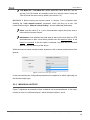
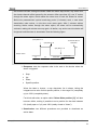
Figure 1 MAXinBOX 8
http://www.zennio.com
Technical Support: http://zennioenglish.zendesk.com
4
MAXinBOX 8
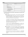
1.2 INSTALLATION
MAXinBOX 8 connects to the KNX bus through the on-board KNX connector.
Once the device is provided with power from the KNX bus, both the physical address
and the associated application program can be downloaded.
This actuator does not need any additional external power since it is entirely powered
through the KNX bus.
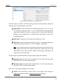
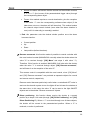
1.- Output Control Button
2.- Output status LED Indicator.
3.- Prog/Test Button.
4.- Programming/Test LED.
5.- Outputs.
6.- KNX Bus Connection.
7.- Output Securing Screws.
Figure 2 MAXinBOX 8. Element Scheme
The functionality of the main elements of the actuator is described below:
Prog/Test button (3): a short press on this button sets the actuator into the
programming mode, making the associated LED (3) light in red.
Note: if this button is held while plugging the device into the KNX bus,
MAXinBOX 8 goes into secure mode. The LED will blink in red every 0.5
seconds.
In case of having enabled the Test On manual control mode through the
corresponding parameter (see section 2.3), a long push (i.e., for at least three
seconds, until the red light from the Prog/Test LED changes to yellow) on this
button enables the manual control over the actuator. Just after releasing the
button, the LED light will become green, indicating the activation of this
manual control. To leave the device manual control, an additional press on
the Prog/Test button will be required (the LED will turn off).
http://www.zennio.com
Technical Support: http://zennioenglish.zendesk.com
5
MAXinBOX 8
While MAXinBOX 8 is under the start-up process –after an ETS download or
a bus power failure–, the Prog/Test LED will blink in blue. During the
execution of the start-up, every order received will be taken into account and
performed immediately once the start-up is over.
Output control pushbuttons (1): permit a manual and individual control of
each of the actuator outputs, provided that such control has been configured.
The LED indicator next to every pushbutton (2) will show a green light
whenever the corresponding output is active.
Outputs (5) and Output Securing Screws (7): slots for the insertion of the
electrical output cables, and screws for properly securing them once inserted.
Please refer to section 2.2 for details about the correct cable connection order
for controlling shutters.
To get detailed information about the technical features of MAXinBOX 8, as well as on
security and on the installation procedure, please refer to the device Datasheet,
bundled with the original packaging and also available at: http://www.zennio.com .
http://www.zennio.com
Technical Support: http://zennioenglish.zendesk.com
6
MAXinBOX 8
2 CONFIGURATION
2.1 INDIVIDUAL OUTPUTS
The MAXinBOX 8 actuator incorporates 8 relay outputs that allow controlling different
loads autonomously. Each output can be enabled or disabled independently and
perform different functionalities.
Every individual output can be configured as normally open (the activation of the
output makes the relay close) or normally closed (the deactivation of the output
makes the relay open).
Besides the output type, MAXinBOX 8 allows the configuration of the following
functionalities for the individual outputs:
Timers. Permit a timed control over the outputs, being possible to set times
for the switch-on and for the switch-off of the output.
Scenes. Allows running and/or saving specific actions over the output/s on
the reception of a scene object. The status of the outputs will vary depending
on the action set for the parameterised scene.
Alarm. Allows changing the status of the output on the reception of an alarm
message, being possible to configure the state the output will be set to, both
on the alarm activation and on the alarm deactivation.
Note: the alarm behaves with priority over any other functionality.
Start-up configuration: default or custom.
All these configuration options are explained in detail in section 0.
2.2 SHUTTER CHANNELS
The MAXinBOX 8 output channels allow controlling up to 4 different shutter drives (or
similar window/door automated systems). Thus, it is possible to control the movement
of the shutters in the domotic system:
http://www.zennio.com
Technical Support: http://zennioenglish.zendesk.com
7
MAXinBOX 8
Basic control: simple up/down movements.
Precise control: precise control of the shutter and of the slats/lamellas (if
any).
Each channel (A, B, C or D) consists of two consecutive individual outputs; i.e.,
Channel A is made of the individual outputs 1 and 2; channel B consists of outputs 3
and 4; and so on. The first output of every will send the orders to raise the shutter,
whereas the second output will send the orders to lower the shutter. Therefore, the
cables of the shutter motor carrying out these actions should be properly connected to
the corresponding output of the channel to perform the required action.
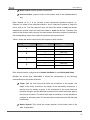
Table 1 shows the action carried out by the outputs of each channel:
Channel
A
B
C
D
Outputs
Action
1
Move up
2
Move down
3
Move up
4
Move down
5
Move up
6
Move down
7
Move up
8
Move down
Table 1 Shutter channels: actions of the outputs
Each channel can be configured as a Shutter (No Slats) or as a Blind (with Slats).
Besides the shutter type, MAXinBOX 8 allows the configuration of the following
functionalities for the shutter channels:
Times. Sets the main times that define the movement of the shutter: the
length of the rising movement, the length of the descending movement, a
security time for making a pause in the movement of the motor when the
direction changes, and an additional movement time when the shutter gets to
its limit (top or bottom). For blinds with slats (or lamellas), it is also possible to
configure a “secondary time” for the entire slat movement and for the slat step
movements.
Status objects. They report the current position of the shutter (and of the
slats, if applicable).
http://www.zennio.com
Technical Support: http://zennioenglish.zendesk.com
8
MAXinBOX 8
Precise control. Allows moving the shutter to a particular position. Moreover,
for blinds with slats, it is also possible to establish a particular position for the
slats (value between 0% and 100%).
Scenes. Allows running and/or saving a specific action over the channel/s
where this function is enabled.
Alarms. Two alarms are available for each shutter channel. The
parameterised action will be executed when an alarm event is received.
Reverse movement. Allows an inverse shutter control.
Direct positioning. Function that permits moving the shutter to a preset
specific position by sending a 1-bit communication object.
Start-up configuration. Default or custom.
All these options are explained in detail in section 0.
2.3 MANUAL CONTROL
MAXinBOX 8 allows manually switching the state of its 8 output relays through the
respective pushbuttons on the top of the device. Therefore, a specific pushbutton is
available per output (see Figure 2).
Manual operation can be done in two different ways, referred to as Test On Mode
(intended for testing the domotic system during the configuration of the device) and
Test Off Mode (intended for using it anytime). Whether both, only one or none of these
modes will be available can be parameterised from ETS. Moreover, it will be possible
to enable a specific binary object for locking and unlocking the manual control in
runtime. See section 3.2 for further details on the device parameterisation.
Note: the Test Off mode will be available anytime (unless it has been disabled by
parameter) with no need of a specific activation after a download or a reset. Accessing
the Test On mode, on the contrary, will require (unless disabled by parameter) pressing
the Prog/Test button for at least three seconds, until the LED turns yellow. From that
moment, once the button is released, the LED light will turn green to confirm that the
device has switched from the Test Off mode to the Test On mode. After that, an
additional press will turn the LED off, setting the device back to the Test Off mode.
http://www.zennio.com
Technical Support: http://zennioenglish.zendesk.com
9
MAXinBOX 8
2.3.1 TEST OFF MODE
Under the Test Off Mode, outputs can be controlled through both communication
objects and through the actual pushbuttons located on the top of the device (see Figure
2).
When one of these buttons is pressed, the output will behave as if an order had been
received through the corresponding communication object (see section 3.2)
The behaviour of the outputs upon a button press depends on whether the outputs
have been configured as individual outputs or as a shutter channel.
Individual Output: a simple press, short or long, will make the output switch
its state, as if a 0/1 order had been received through the “[SX] ON/OFF”
communication object. Once the output state changes, a message is sent
through the corresponding status object, “[SX] Status”.
Shutter Channel: when the button is pressed, the device will act over the
output according to the length of the button press and to the current state.
A long press makes the shutter start moving (upwards or downwards,
depending on the actual button being pressed), lighting the LED in green
until the end of the movement, unless no further movements are possible
when the button is pressed because of being the shutter in a final position.
Hence, the output will behave the same as when the device receives an
order through the “[CX] Up/Down” communication object.
A short press will make the shutter drive stop the movement (if in motion),
as it would happen on the reception of a message through the “[CX] Stop”
object. In case of not being the shutter in motion, pressing the button does
not cause any action, unless the shutter features slats/lamellas – in such
case, a step movement (up/down, depending on the button pressed) of the
slats will take place, as if the equivalent order had been received through
the “[CX] Stop/Step” communication object..
Disabled output: presses made on the pushbutton of a non-enabled output
will be ignored.
http://www.zennio.com
Technical Support: http://zennioenglish.zendesk.com
10
MAXinBOX 8
Note: multiple shutter channels can be manually controlled at the same time by
pressing their corresponding pushbuttons.
Regarding the lock, timer, alarm, scene and status object sending functions, the device
will behave under the Test Off mode as usual: button presses are entirely analogous to
the reception of the corresponding orders from the KNX bus.
2.3.2 TEST ON MODE
Once the Test On mode has been activated, it will only be possible to control the
outputs through the on-board pushbuttons. Orders received through communication
objects will be always ignored, with independence of the channel or the output they are
actually addressed.
Depending on whether an output has been parameterized as an individual output or as
a part of a shutter channel, its reaction to the button presses will differ.
Individual output: short or long pressing the associated button will commute
the state of the relay, therefore switching the state of the output (from “on” to
“off”, or vice versa).
Shutter channel: a press on the corresponding button will set the shutter
drive in motion, staying this way until the button is released, thus ignoring the
current position of the shutter and the parameterized up/down times.
Disabled output: under the Test On mode, short and long presses will cause
the same effect for disabled outputs as for individual outputs (i.e., the relay
will switch its state).
The lock, timer, alarm, scene and status object sending functions will not work while
the device is under the Test On mode.
Note: the device is factory delivered with all the output channels configured as
shutters, and with both manual control modes (Test Off and Test On) enabled.
http://www.zennio.com
Technical Support: http://zennioenglish.zendesk.com
11
MAXinBOX 8
3 ETS PARAMETRISATION
To begin with the parameterisation of the MAXinBOX 8 actuator it is necessary, once
the ETS application is running, to import the database of the product (MAXinBOX 8
application program).
Next, the device must be added to the project where desired. Finally, right-click on the
device and select "Edit parameters" to start with the configuration.
The following sections provide a detailed explanation about each of the different
functionalities of the application in ETS.
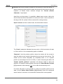
3.1 DEFAULT CONFIGURATION
This section shows the default configuration the device parameterisation starts from.
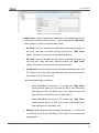
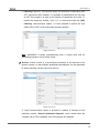
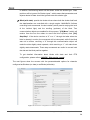
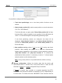
After entering the parameter edition for the first time, the following window comes up:
Figure 3 Configuration screen by default
As shown in Figure 3, outputs, inputs and logical functions are disabled by default, so
there will be no communication objects available until the user enables some of the
functions of the actuator.
If "Sending of indication objects on bus voltage recovery" is set to “Yes”, two new
1-bit communication objects will show up ("Reset 0" and "Reset 1"), which will send to
the KNX bus the values "0" and "1" respectively after a bus power failure, in order to
recover the communication with the rest of the devices in the facility. This transmission
may be immediate or after a configurable delay (in seconds).
http://www.zennio.com
Technical Support: http://zennioenglish.zendesk.com
12
MAXinBOX 8
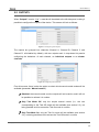
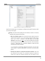
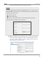
3.2 OUTPUTS
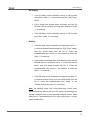
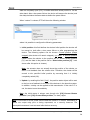
When “Outputs” is set to “Yes”, a new tab will be added to the left-side panel, making it
possible to configure the outputs of the device. This screen will look as follows:
Figure 4 Configuring the outputs
The outputs are grouped into channels (Channel A, Channel B, Channel C and
Channel D, all disabled by default), with two outputs each. A drop-down list permits
configuring the behaviour of each channel, as individual outputs or as shutter
channels.
Figure 5 Configuring the channels
From this screen, there is also the option to select which manual control modes will be
available (parameter “Manual control”):
Disabled: the manual control over the outputs will not be active, and it will not
be possible to activate it in runtime.
Only Test Mode Off: only the simple manual control (i.e., the one
corresponding to the Test Off mode) will be available (see section 2.3), not
being possible at all to access the Test On mode in runtime.
Only Test Mode On: only the Test On mode will be available (see section
2.3), not being possible at all to access the Test Off mode in runtime.
http://www.zennio.com
Technical Support: http://zennioenglish.zendesk.com
13
MAXinBOX 8
Test Mode Off + Test Mode On: default parameter value. Both the Test On
and the Test Off modes are available under the manual control, being the
Test Off mode the active one by default (see section 2.3).
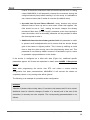
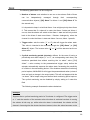
MAXinBOX 8 allows locking the manual control in runtime. This is possible after
enabling the “Lock manual control?” parameter, which will bring up a new 1-bit
communication object, “Manual control locking”, and two additional parameters:
Value: sets the value (0 or 1) the communication object should be sent to
lock/unlock the manual control.
Initialization: sets whether the initial state of the lock function (after an ETS
download/reset or after a bus failure) should have the previous value, or be
locked or unlocked. If the first option is selected, the state will be unlocked
after the very first start-up of the device.
While the manual control remains locked, presses on the on-board pushbuttons will be
ignored.
Figure 6. Manual control type and lock
In the next sections the configurable parameters are explained in detail, depending on
the selected output type.
3.2.1 INDIVIDUAL OUTPUTS
Figure 7 represents an example of how a channel can be parameterised: in this case,
channel A is set to “individual outputs”, which activates outputs 1 and 2.
http://www.zennio.com
Technical Support: http://zennioenglish.zendesk.com
14
MAXinBOX 8
Figure 7 Channel A configured as individual outputs
Once the output is enabled, the ETS topology window will automatically display the
following communication objects (1-bit each):
[OX] ON/OFF: allows switching the corresponding output to the “on” or the
“off” states by sending the value "1" or "0", depending on the parameterised
output type. Whether the relay is actually open or closed under each state
depends on the normally open / normally closed configuration of the output,
as explained below.
[OX] Status: shows the current status of the output (on or off).
[OX] Block: allows locking/unlocking the output (i.e., disabling/enabling its
control) by sending the values "1" or "0" to the object, respectively.
Note: only the Alarm function has a higher priority than the lock function; if an
alarm signal arrives when the output is locked, the output will be set to the
state defined by the alarm function. When the alarm gets deactivated, the
output returns to the lock status.
The first thing to be parameterised is the type of each output of the channel:
Normally open: the output will be considered as “on” when the relay stays
closed and “off” when the relay stays open.
Normally closed: the output will be considered as “on” when the relay stays
open and “off” when the relay stays closed.
Next, the list of functions available for each output:
Timers: allow performing a timed control of the outputs, both through a
simple timer and/or through an intermittent sequence (flashing).
http://www.zennio.com
Technical Support: http://zennioenglish.zendesk.com
15
MAXinBOX 8
Figure 8 Timers screen. Simple timer
Simple timer: allows automatically switching on (and afterwards off) the
output on the reception of the values “1” and “0” through the “[OX] Timer”
object, subject to a set of parameterisable times:
•
On Delay: time the actuator will wait before switching the output on
once the ON order has been received (through the “[OX] Timer”
object). The value “0” will cause an immediate response.
•
Off delay: time the actuator will wait before switching the output off
once the OFF order has been received (through the “[OX] Timer”
object). The value “0” will cause an immediate response.
•
On Duration: time the output remains ON before switching back to the
OFF state. A “0” in this field means the output will remain permanently
ON (unless an OFF order arrives).
These parameters apply as follows:
o
When MAXinBOX 8 receives a "1" through the "[OX] Timer"
communication object, an ON order is sent to the output relay
after waiting for the “On Delay” time. The output will switch off
again after the “On Duration” time (if other than 0).
o
When MAXinBOX 8 receives a "0" through the "[OX] Timer"
communication object, an OFF order is sent to the output relay
after waiting for the “Off Delay” time.
•
Multiply: allows progressively increasing (multiplying), in runtime, the
On Duration time or the On/Off delays of the output. Two situations are
distinguished:
http://www.zennio.com
Technical Support: http://zennioenglish.zendesk.com
16
MAXinBOX 8
o
No multiply:
•
If the On delay count is already running, it will be reset
every time a new “1” is received through the “[OX] Timer”
object.
•
If the output has already been activated and the On
Duration time is counting, it will be reset whenever a new
“1” is received.
•
If the Off delay count is already running, it will be reset
every time a new “0” is received.
o
Multiply:
•
If the On delay count is already running and the value “1”
is received several times through the “[OX] Timer” object,
then the actual delay time will be “n” times the
parameterised time, being “n” the number of times the
value “1” is received.
•
If the output has already been activated and while the On
Duration time is counting the value “1” is received several
times, then the actual duration will be “n” times the
parameterised time, being “n” the number of times the
value “1” is received.
•
If the Off delay count is already running and the value “0”
is received several times, then the actual delay time will
be “n” times the parameterised time, being “n” the
number of times the value “0” is received.
Note: the Multiply option may result particularly useful under
parameterisations with no ON and OFF delays. Nevertheless, as
already explained and as the following example shows, these
delay times, if parameterised with a value other than 0, do also
admit multiplication.
http://www.zennio.com
Technical Support: http://zennioenglish.zendesk.com
17
MAXinBOX 8
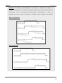
Example: the following is parameterised: On Delay = 3 seconds; Off Delay = 3
seconds, On Duration = 5 seconds. The graphs bellow reflect some possible situations
if the values “0” or “1” are received from the (which is represented as →0 and →1),
respectively for the cases of having the “multiply” option enabled and disabled.
With no multiplication:
With multiplication:
http://www.zennio.com
Technical Support: http://zennioenglish.zendesk.com
18
MAXinBOX 8
Flashing (Figure 9). This function allows the execution of alternating ONOFF sequences when needed. It is possible to parameterise the ON and
an OFF time lengths, as well as the number of repetitions (the value “0”
makes the sequence endless, until a “0” is received through the “[OX]
Flashing” communication object). It is also possible to define the final
status (ON or OFF) of the output after the last repetition.
Figure 9 Flashing
Note: MAXinBOX 8 allows parameterising both a simple timer and an
intermitting sequence for the same output.
Scenes: scenes consist of a synchronised activation of the devices in the
domotic system, so that different predefined atmospheres can be generated
by simply sending a scene value over the bus.
Figure 10 Scenes
A 1-byte communication object is provided in relation to Scenes for the
individual outputs: "Scenes (Individual Outputs)", which shows when the
"Outputs" tab in ETS is enabled, even if the outputs are disabled.
http://www.zennio.com
Technical Support: http://zennioenglish.zendesk.com
19
MAXinBOX 8
In the case of the individual outputs, scenes allow linking a numerical value
(between “1” and “64”, while “0” means that the option is disabled) to an
output state (OFF or ON). Thus, when the defined scene value is received
(decreased by one) through the Scenes object, the parameterised action for
the output (a switch-off or a switch-on) will be performed, making it possible
to create different ambient scenarios in the domotic system.
Besides running scenes, it is possible to learn (save) scenes, taking into
account that the associated numerical values for learning scenes are in the
range 128-191, which correspond to saving scenes 1-64 respectively.
MAXinBOX 8 allows defining up to 5 different scenes for each output.
Alarm: for each output it is possible to configure an alarm, which, once
triggered, will have priority over the rest of the orders that the actuator may
receive, i.e., any order received while the alarm is active will be ignored until
the alarm situation stops.
Figure 11 Alarm
The following parameters can be configured for alarms:
Trigger value: sets the value that will trigger the alarm ("1" or "0") if
received through the “[OX] Alarm” object. The opposite value (“0” or “1”)
will be considered as the no alarm value.
Cyclical monitoring period (minutes): defines, for the case of having a
periodically-sent alarm object (“1” or “0”, as corresponding each time), the
maximum permitted time without receiving the “no alarm” value (“[OX]
Alarm” = value contrary to the parameterised trigger value) before the
actuator automatically assumes the alarm state, foreseeing the possibility
of a failure in the transmitting device. If for whatever reason the monitoring
period expires, MAXinBOX 8 will trigger the parameterised action (unless it
does not imply a change in the output status). This will not happen while
http://www.zennio.com
Technical Support: http://zennioenglish.zendesk.com
20
MAXinBOX 8
the “no alarm” value keeps being sent before each monitoring period
expires. The cyclical monitoring can be disabled by simply setting a “0”
under this filed.
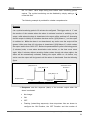
The following example is provided for a better comprehension:
Example:
Let a cyclical monitoring period of 2 minutes be configured. The trigger value is “1” and
the reaction of the actuator when the alarm is activated consists in switching on the
output, while when the alarm is deactivated, the output will be switched off. Assuming
that the output is initially off, the alarm becomes active (“[OX] Alarm=1”), so the output
is switched on. While the alarm is not deactivated, any action over the output will be
ignored. After some time (t2), the alarm is deactivated (“[OX] Alarm=0”), which makes
the output switch from ON to OFF. Before the parameterised cyclical monitoring period
(2 minutes) ends, a new alarm deactivation order arrives, so the time count starts
again. After 2 minutes without receiving further values through the alarm object, the
alarm will be automatically activated, making the output switch on. As before, any
action over the output will be ignored until the alarm is deactivated. See the following
figure.
“[OX] Alarm”=1
Automatic Alarm
Activation
“[OX] Alarm”=0
“[OX] Alarm”=0
Output status
t1
t2
2 minutes
2 minutes
Response: sets the response (state) of the actuator output when the
alarm is activated:
•
No change.
•
ON.
•
OFF.
•
Flashing (intermitting sequence): three drop-down lists are shown to
configure the ON Duration, the OFF Duration and the number of
http://www.zennio.com
Technical Support: http://zennioenglish.zendesk.com
21
MAXinBOX 8
repetitions of the sequence.
Deactivation: two different procedures are provided to deactivate an
active alarm:
•
Normal: depending on what was parameterised under “Trigger Value”,
the alarm will become inactive as soon as the actuator receives a “0” or
a “1” through the alarm object.
•
Frozen: this method requires a normal deactivation, plus the reception
of the value “1” over the “[OX] Unfreeze Alarm” object (if the latter
does not occur, the alarm will still remain triggered). This method
makes the channel output remain locked (even when the alarm
situation is over) until it is externally (or manually) enabled.
End (reaction when alarm ends): this parameter sets the state that will
be adopted by the output once the alarm finishes:
•
No change
•
ON
•
OFF
•
Last (the output returns to the state it had before the alarm).
Start-up configuration: defines the desired state (ON/OFF) to be adopted by
the output when the device recovers from a bus power failure, or after an ETS
download/reset. A default or a custom configuration may be set.
Selecting the default configuration will make the output stay off after a partial
or complete ETS download, while after a bus power failure, the state of the
output will be the same it had before the failure (ON or OFF).
If “custom” is chosen, ETS will show the following window:
Figure 12 Custom start-up configuration.
Where the following parameters can be configured:
http://www.zennio.com
Technical Support: http://zennioenglish.zendesk.com
22
MAXinBOX 8
Initial status: this field defines the initial state of the output after a bus
power failure or after a download. The following options are available: last
saved position (i.e., the state of the output before the bus power failure),
ON or OFF.
Update: enabling this field (“Yes”) will make the actuator send the output
status to the bus (through the corresponding communication object) after
the start-up or after a bus failure, as a feedback for the rest of the devices
in the domotic system. A parameterisable delay can also be applied to this
transmission. If the delay is set to 0, the status will be sent immediately.
The state of the output is always sent through the “[OX] Status” object.
3.2.2 SHUTTER CHANNEL
MAXinBOX 8 also allows configuring its outputs as shutter channels, making it possible
to control up to 4 separate shutters in a domotic facility.
When a channel is configured in ETS as a shutter channel, a 1-bit communication
object (“[CX] Lock”) related to that particular channel becomes visible. This object
allows locking the channel outputs (i.e., disabling the control over them through both
the ON/OFF and the timed control objects) when it is received with value “1”. Moreover,
if the shutter is already in motion at the moment of being locked, the movement will be
interrupted and any order over it will be ignored. The channel outputs will become
unlocked when a “0” is sent through this object.
Note: only the “alarm” function has a higher priority than the “lock” function. If an alarm
signal arrives while the channel is locked, the shutter will adopt the position configured
for the alarm. Once the alarm is deactivated, the shutter will recover the position
defined for the locked status.
The first parameter to be configured is the shutter type:
Shutter (no slats): typical shutter drives with simple up/down movements. If
this type is selected, two communication objects are enabled, “[CX] Move”
and “[CX] Stop”, to move the shutter up/down and to stop it, respectively.
http://www.zennio.com
Technical Support: http://zennioenglish.zendesk.com
23
MAXinBOX 8
In addition, the following remark will be shown under this shutter type: "Slats
positions will be ignored for Shutter types", which means that parameters and
objects related to slats should be ignored under this shutter type.
Blind (with slats): special slat shutter drives where both the shutter itself and
the slats/lamellas are controlled with a single engine. MAXinBOX 8 allows
controlling both movements: the slat rotation (which permits varying the level
of the incident light) and the scrolling (up/down) of the blind. Two
communication objects are enabled for this purpose: "[CX] Move" (which will
receive from the bus the orders to move the blind up/down) and "[CX]
Stop/Step". If the device receives a “0” or a “1” through the latter when the
blind is already in motion, the movement will be interrupted, while if the blind
was not in motion, receiving a “0” through this communication object will
make the slats slightly rotate upwards, while receiving a “1” will make them
slightly rotate downwards. These step movements are useful to correct both
the slat and the blind position together.
To get detailed information about blinds with slats and their ETS
configuration, please refer to ANNEX I. Slat precise control.
The next figures show the screens with the parameterisable options for channels
configured as Shutters (no slats) or as Blinds (with slats).
Figure 13 Channel A configured as a shutter (no slats)
http://www.zennio.com
Technical Support: http://zennioenglish.zendesk.com
24
MAXinBOX 8
Figure 14 Channel B configured as a blind (with slats)
Apart from the shutter type, it is necessary to configure some specific functions, which
are common to both types:
Times: this section allows setting the time intervals (in tenths of a second)
that define the movement of the shutter.
Main time (Shutter length): this is the time the motor needs to move the
shutter all the way down or up. In case it does not take the same time to
raise it as to lower it, parameter “Are total times up and down
different?” should be set to “Yes”. In such case, this Main time will define
the time required to move the shutter all the way down, while a secondary
parameter (“Total time up”) will become available to define the time
required for the inverse movement.
It is not necessary to periodically calibrate this parameter, since the exact
shutter position is stored by MAXinBOX 8 at any time, even after power
failures.
Security time (pause to change the movement direction): this is the
time reserved by the actuator, as a preventive measure to protect the
shutter drive, when the movement switches from one direction to the
http://www.zennio.com
Technical Support: http://zennioenglish.zendesk.com
25
MAXinBOX 8
inverse. If the device receives an order to lower the shutter while it is being
raised, MAXinBOX 8 will temporarily interrupt the movement (during the
configured security time) before lowering it (or vice versa). It is advisable to
set a value not lower than 5 tenths of a second (the default value).
Are total time Up and Down different?: heavy shutters may require
different times to move up and to move down. When this happens, this
field should be set to “Yes”, making the device interpret the already
mentioned “Main time (Shutter length)” parameter as the time required to
lower the shutter, while a secondary parameter will be provided to define
the time required to raise it.
Additional time when the shutter gets the limit: this parameter is useful
to prevent small maladjustments and to ensure that the shutter always
gets to the lowest or highest position. This is done by defining an extra
time to keep the drive moving once the rising/lowering times end. This
parameter is not visible by default; however it is advisable to give it a value
to guarantee a proper behaviour in the shutter.
If the shutter is configured as a blind with slats (Figure 14), additional specific
parameters appear. All of them are explained in detail under ANNEX I. Slat precise
control.
Note: after programming the device from ETS and unless a custom start-up
configuration has been parameterised, MAXinBOX 8 will assume the shutter as
completely raised, so any raising order will be ignored.
The following is an example of a possible shutter configuration.
Example:
Channel A (shutter without slats) takes 15 seconds to be lowered and 20 to be raised.
Additional times for direction changes (5 tenths of a second) and at the end of the
movement (2 seconds) are also required. The corresponding parameterisation is as
follows:
http://www.zennio.com
Technical Support: http://zennioenglish.zendesk.com
26
MAXinBOX 8
The following parameters add functionality or special features to both shutter types
(with or without slats):
Status object: this function provides a 1-byte communication object ("[CX]
Current Shutter Position") which will show, at any time, the exact position of
the shutter in percentage (%). This object returns the value “0” (or 0%) when
the shutter in completely up and “255” (or 100%) when it is completely down.
The remaining values represent intermediate positions.
It is possible to set, by parameter, whether the shutter position will be sent
every second or not. This is done by enabling or disabling “Send current
shutter position every second while moving?”, which appears once the
“Status Object” parameter has been enabled.
For Blinds with slats, the "[CX] Current Slats Position" 1-byte object is also
provided. It will show the value “0” (0%) when the slats are completely "up"
and the value “255” (100%) when the slats are completely "down".
Precise control: this function makes it possible to actually move the shutter
to any position via a 1-byte communication object ("[CX] Shutter
Positioning", in percentage). Every time MAXinBOX 8 receives a new
percentage value through this object (e.g. 50%), the shutter moves to the
corresponding position (e.g., the central position).
For blinds with slats, the actuator also implements the "[CX] Slats
Positioning" 1-byte object for setting the desired position (in percentage) for
the slats.
http://www.zennio.com
Technical Support: http://zennioenglish.zendesk.com
27
MAXinBOX 8
Scenes: this function makes it possible to use scenes to control the shutter. It
allows choosing precise positions where the shutter will be moved to upon the
reception of certain scene numbers through the “Scenes (Shutter
Channels)” 1-byte object.
Apart from running scenes, it is possible to learn (save) scenes, taking into
account that the values that should be received to learn a scene must be in
the range 128-191 (values 0-63 are reserved for running scenes).
Up to 5 scenes can be run and/or leant, for each shutter channel.
Figure 15 Scenes
The “Scene” parameter indicates the scene value (1-64) the shutter will react
to. If this value is 0, the corresponding option is disabled.
“Response” sets the precise position where the shutter will be moved to
when the above scene number (decreased by one) arrives from the bus. The
shutter can be moved completely up, completely down, or to a specific
position (in percentage, from 0% to 100%). In case of choosing the latter, the
"Shutter specific position?" parameter will become visible to allow the
definition of a specific shutter position (through the "Select Shutter Position
[%]" parameter, after selecting "Yes") or to make the shutter stay as is.
For blinds with slats it is also possible to configure a specific position for the
slats (via the "Select Slats Position [%]"parameter) when the configured
scene number is received, or to make them maintain their current position.
http://www.zennio.com
Technical Support: http://zennioenglish.zendesk.com
28
MAXinBOX 8
The following example illustrates the configuration process.
Example:
Consider a facility where 3 scenes will be distinguished (values “4”, “6” and “18”) and
where MAXinBOX 8 will be used to move a blind with slats to precise positions on the
reception of these scene values:
Scene 4: shutter up.
Scene 6: shutter down.
Scene 18: central position (50%). The slats maintain their current position.
The associated parameterisation should be as follows.
Alarms: MAXinBOX 8 allows configuring up to 2 alarms for each shutter
channel. This function is designed for cases in which the actuator must react
to an alarm situation. Having two alarms configured allows carrying out
different reactions to two external events.
Figure 16 Alarms
http://www.zennio.com
Technical Support: http://zennioenglish.zendesk.com
29
MAXinBOX 8
The following parameters can be configured:
Number of alarms: sets whether to use one or two alarms. Both of them
can
be
independently
managed
through
their
corresponding
communication objects (“[CX] Alarm” for Alarm 1 and “[CX] Alarm 2” for
the second one).
It is important to keep in mind that Alarm 1 has a higher priority than Alarm
2. This means that if a channel is under the Alarm 2 state and Alarm 1
occurs, then the shutter will switch to the Alarm 1 state and will only switch
back to the Alarm 2 state once Alarm 1 finishes. Analogously, when the
channel is under the Alarm 1 state and Alarm 2 occurs, Alarm 1 prevails.
Trigger value: sets the value (“1” or “0”) that will trigger the alarm state.
This value is intended to be received through the “[CX] Alarm” (or “[CX]
Alarm 2”) object. The inverse value (“0” or “1”) will be assumed as the no
alarm value.
Cyclical monitoring period (minutes): defines, for the case of having a
periodically-sent alarm object (“1” or “0”, as corresponding each time), the
maximum permitted time without receiving the “no alarm” value (“[OX]
Alarm” = value contrary to the parameterised trigger value) before the
actuator automatically assumes the alarm state, foreseeing the possibility
of a failure in the transmitting device. If for whatever reason the monitoring
period expires, MAXinBOX 8 will trigger the parameterised action (unless it
does not imply a change in the output state). This will not happen while the
“no alarm” value keeps being sent before each monitoring period expires.
The cyclical monitoring can be disabled by simply setting a 0 under this
filed.
The following example illustrates the above behaviour:
Example:
Suppose that a cyclical monitoring period of 3 minutes is configured. The trigger value
is “1” and the reaction of the actuator when the alarm is activated consists in moving
the shutter all the way up, while when the alarm is deactivated, the shutter will be
lowered. Assuming that the shutter has been lowered, when the alarm becomes active
http://www.zennio.com
Technical Support: http://zennioenglish.zendesk.com
30
MAXinBOX 8
the actuator will start raising the shutter. While the alarm stays active, any action over
the shutter channel will be ignored by the actuator. After some time (t2), one “0” arrives
through the alarm object, which makes the alarm turn off and the shutter be raised.
Before the parameterised cyclical monitoring period (3 minutes) ends, a new alarm
deactivation order arrives, so the time count starts again. After 3 minutes without
receiving further values through the alarm object, the alarm will be automatically
activated, making the shutter move up again. As before, any action over the shutter will
be ignored until the alarm is deactivated. See the following figure
“[CX] Alarm”=1
Automatic Alarm
Activation
“[CX] Alarm”=0
“[CX] Alarm”=0
Output status
t1
t2
3 minutes
3 minutes
Response: sets the response order to be sent to the shutter when the
alarm is triggered:
•
Stop.
•
Up.
•
Down.
•
Specific position.
When the latter is chosen, a new drop-down list is shown, letting the
integrator set a value for this specific position, in the range 0% (completely
up) to 100% (completely down).
For blinds with slats, an option called "Select Slats position [%]" will also
become visible, making it possible to set a position for the slats between
0% (totally open or "up") and 100% (totally closed or "down").
Deactivation: two different procedures are provided to deactivate an
active alarm:
http://www.zennio.com
Technical Support: http://zennioenglish.zendesk.com
31
MAXinBOX 8
•
Normal: the alarm will become inactive as soon as the actuator receives
a “0” or a “1” (the inverse of the parameterised trigger value) through
the corresponding alarm object.
•
Frozen: this method requires a normal deactivation, plus the reception
of the value “1” over the corresponding unfreeze alarm object (if the
latter does not occur, the alarm will still be active). This method makes
the channel output remain locked (even when the alarm situation is
over) until it is externally (or manually) enabled.
End: this parameter sets the desired shutter position once the alarm
becomes inactive:
•
Current position.
•
Up.
•
Down.
•
Last position (before the alarm).
Reverse movement: this function makes it possible to control a shutter with
the usual orders inverted (MAXinBOX 8 normally raises the shutter when the
value "0" is received through "[CX] Move" and stops it with value "1").
Therefore, if this function is enabled, MAXinBOX 8 will also raise the shutter
when the value "1" is received through object "[CX] Reverse movement",
and will lower it on the reception of the value “0”.
This reverse control is compatible with the usual control, since “[CX] Move”
and “[CX] Reverse movement” are provided as separate objects for normal
and reverse control, respectively.
Reverse control becomes particularly useful when a centralised OFF order is
sent over the domotic system to turn the lights off and to lower the shutters at
the same time. In this case, the value “0” can be sent to the light ON/OFF
objects and to the shutter “Reverse movement” objects.
Direct positioning: this function allows moving the shutter to a preset
position by a simple 1-bit order (through “[CX] Direct Positioning” and “[CX]
Direct Positioning 2”). When a “1” is received through one of these objects,
the shutter will be moved to the parameterised position. When a “0” is
received, no action is performed.
http://www.zennio.com
Technical Support: http://zennioenglish.zendesk.com
32
MAXinBOX 8
Figure 17 Direct positioning
It is possible to configure the following parameters:
Total direct positionings: one or two direct position functions can be
defined.
Select shutter position [%]: sets the exact position to move the shutter to
(0%=Top; 100%=Bottom).
For blinds with slats, an option called "Select Slats position [%]" will also
become visible, making it possible to set a position for the slats when the
value "1" is received through the corresponding positioning object.
If two direct positioning controls are configured, two boxes will be
displayed: “Select Shutter Position 1” and “Select Shutter Position 2”
(as well as "Select Slats position 1" and "Select Slats position 2" for
blinds with slats).
New positions saving: allows (“Yes”) or not (“No”) saving new direct
positions. After enabling this option, one or two new communication
objects appear (depending on the number of direct positioning controls):
“[CX] Save Position” and “[CX] Save Position 2”. To overwrite the
parameterised direct position it is necessary to send a “1” to these objects
when the shutter is at the desired position.
Note: saving a new position is not possible while the shutter is moving.
Start-up configuration: defines the shutter state that the device will
assume/order when it recovers from a bus power failure, or after an ETS
download. A default or a custom configuration may be selected.
If “Default” is chosen, after a partial or a complete download from ETS,
MAXinBOX 8 will assume the shutter is completely up (0%), independently of
its actual state. For blinds with slats, MAXinBOX 8 also assumes that the
http://www.zennio.com
Technical Support: http://zennioenglish.zendesk.com
33
MAXinBOX 8
slats are completely open (0%), no matter what their actual position is. On the
other hand, after a bus power failure, the device will assume the shutter (and
the slats) maintains the same state as before the power failure.
When “custom” is chosen, ETS will show the following window:
Figure 18 Custom Start-up configuration
where it is possible to configure the following parameters:
Initial position: this field defines the desired initial position the shutter will
be moved to, both after a bus power failure or after programming the
device. The following options can be chosen: Current position (keeps
stopped) (the shutter will remain stopped), up, down, or specific position
(which moves the shutter to the position set for "Select shutter position
[%]" and the slats to the position set for “Select slats position [%]”, both
shown after this option is chosen).
Note: the actuator does not actually know the position of the shutter, as
there is no feedback from the shutter drive. Therefore, the shutter will be
moved to the specified initial position by assuming that it is initially
completely raised (0%).
Update: by enabling this field (“Yes”), the position status object will be sent
to the bus as a feedback for the rest of the devices in the domotic system.
In addition, a delay can be applied to this transmission. If the value “0” is
set, the status is sent immediately.
Note: the initial status is always sent through the “[CX] Current Shutter
position” (and "[CX] Current Slats position", for slats) object.
Note: in the event of a bus power failure while the shutter is in motion, MAXinBOX 8
opens the output relay prior to being unpowered, as a security measure. The
interrupted movement is not resumed after the bus recovery.
http://www.zennio.com
Technical Support: http://zennioenglish.zendesk.com
34
MAXinBOX 8
3.3 LOGICAL FUNCTIONS
This option in MAXinBOX 8 makes it possible to perform mathematical or binary logic
operations to incoming values received from the KNX bus, and to send the result
through other communication objects specifically enabled in the actuator for this
purpose.
Up to 10 different and independent logical functions can be enabled, being each of
them capable of carrying out a maximum of 4 operations. To use any of them, it is
necessary to enable it from the following ETS screen, which becomes available after
selecting “Yes” under Logical Functions in the General parameter screen.
Figure 19 Logical functions
To get further information about how to use and parameterise the logical functions,
please refer to the "Logical Functions X10" specific document, available at
http://www.zennio.com.
http://www.zennio.com
Technical Support: http://zennioenglish.zendesk.com
35
MAXinBOX 8
ANNEX I. SLAT PRECISE CONTROL
Zennio actuators allow controlling the movement of shutters, blinds or any other
window/door automated drives, as long as they match one of the following types:
Shutters (with no slats).
Blinds (with slats/lamellas).
Depending on the drive type, the MAXinBOX 8 application program will show different
options.
This particular section is referred to the parameterisation of blinds with slats.
To begin with, it is important to keep in mind the criteria followed by the actuator for
shutter positioning:
The shutter is in the “up” position (0%, in percentage) when it is completely
open.
The shutter is in the “down” position (100%, in percentage) when it is
completely closed.
While the slat positioning criteria is as follows:
The slats are in the “up” position or “open” (0%, in percentage) when their
position is such that they can only move downwards.
The slats are in the “down” position or “close” (100%, in percentage) when
their position is such that they can only move upwards.
Figure 20 shows a scheme of the positions the slats may adopt.
It is necessary to take into account that shutter actuators control shutter drives without
any feedback about their exact position, and that the movement of the slats relays
entirely on the movement of shutter drive itself. This means that a movement in the
slats will always provoke a certain change in the position of the shutter.
http://www.zennio.com
Technical Support: http://zennioenglish.zendesk.com
36
MAXinBOX 8
SUN
Slats can only move
downward
Slats can move
upward…
…and also
downward
Slats can only move
upward
Figure 20 Slat positions
The ETS configuration screen for Blinds with slats is shown next, as well as the details
about the available options:
Figure 21 Blinds with slats. Configuration screen (ETS)
As shown in Figure 21, for this type of shutters various time parameters need to be
parameterised: on the one hand, time parameters referred to the movement of the
blind: “Main Time (shutter length)”, “Security time”, “Are total time up and down
http://www.zennio.com
Technical Support: http://zennioenglish.zendesk.com
37
MAXinBOX 8
different?” and “Additional time when shutter gets the limit”. All of them were
already explained in Section 3.2.2 of this manual.
On the other hand, time parameters referred to the movement of the slats:
Secondary time (slats length): sets the time, in tenths of a second, the drive
takes to perform a complete slat movement cycle from 0% (completely "up")
to 100% (completely "down"), or vice versa. This time must be manually
measured.
Slats Step Time: sets the time, in tenths of a second, the drive will keep
moving the slats every time it receives the order to perform an up/down step
movement ("[CX] Stop/Step"=0 or 1, respectively), assuming that the blind is
stopped. These step orders allow gradually rotating the slats and modifying
their position (%), which may be very useful to prevent glare, for example
after a change in the position of the sun.
Note: in case of joint-controlling slat step movements of multiple shutter
channels together through the same group address, the time configured for
this parameter is recommended to be slightly greater than N tenths of a
second (where N is the number of the channels that have been enabled and
configured as “blind with slats”) in order to ensure that rapidly sent
consecutive orders are properly processed.
Note: times referred to slat movements must be shorter than those configured for blind
movements (usual configuration).
Besides defining these times, it will be necessary to configure the following options,
which are specific for blinds with slats:
Maintain slats position when shutter completes motion?: this option
allows choosing whether the slats should recover their position after the blind
reaches the desired position, or not.
Example:
Suppose the parameter “Maintain slats positioning when shutter completes motion?”
has been enabled. The initial position of the slats is 50% and the initial position of the
blind is 0% (up). An order to lower the blind is received, thus making the blind (and
http://www.zennio.com
Technical Support: http://zennioenglish.zendesk.com
38
MAXinBOX 8
therefore the slats) start moving downwards, until the position of the blind reaches
100%. At this point, the blind has completed its movement, and MAXinBOX 8 will revert
the position of the slats by additionally moving the drive back until they reach the
position they had before (50%, in this example), thus causing a minor deviation in the
position of the blind.
If parameter “Maintain slats positioning when shutter completes motion?” had not been
enabled, when the position of the blind reached 100% (down), the slats would have
maintained their resulting position after the movement of the blind.
Slats position at Bottom pos. [%]: allows establishing the slats position (in
percentage) when the blind is completely closed (i.e., its position is equal to
100%).
This means that, when the blind stops moving downwards and reaches
100%, the slats will correct their position to the one established by parameter.
Apart from these configuration options, it is necessary to define the "Slats specific
position" for those enabled functions where particular positions are required to be
parameterised. These functions are:
Scenes. “Response: Specific position”. The positions of the blind and the
slats (in percentage) can be configured independently.
Alarms. “Response: Specific position”. The same as above.
Direct positioning. Independent configuration of positions 1 or 2
(depending on the parameterised number), in percentage, of the blind and
the slats.
Start-up configuration. “Initial position: Specific position”. The position
percentages of the blind and slats can be configured independently.
To obtain further information about the configuration and options of the functions of the
shutter channels, please refer to the section 3.2.2 of this manual.
http://www.zennio.com
Technical Support: http://zennioenglish.zendesk.com
39
MAXinBOX 8
ANNEX II. COMMUNICATION OBJECTS
“Functional range” shows the values that, with independence of any other values permitted by the bus according to the object size, may be of any use or have a particular
meaning because of the specifications or restrictions from both the KNX standard or the application program itself.
“1st boot” shows the cases where an object is assigned a certain value by the application program after a device download or a full reset. In case the value of such assignment
can be parameterised, √ is shown in column “P”. Objects showing a hyphen (-) are not assigned a particular value and therefore can be assumed to be initialised with the value “0”.
Moreover, if the object is sent (or is there an option to send it) to the bus (write or read requests) after a download or a device reset from ETS, the marks (W) or (R) will be shown.
“Reboot” shows the cases where an object is assigned a certain value by the application program after a bus power failure. In case the value of such assignment can be
parameterised, √ is shown in column “P”. Objects showing a hyphen (-) are not assigned a particular value and therefore can be assumed to maintain their previous value after the
failure. Moreover, if the object is sent (or is there an option to send it) to the bus (write or read requests) after a bus failure, the marks (W) or (R) will be shown.
Number
Size
I/O
Flags
Data type (DPT)
0
1
1 Byte
1 Byte
I
I
C--WC--W-
DPT_SceneControl
DPT_SceneControl
Functional range 1st boot P Reboot P Name
0-63, 128-191
0-63, 128-191
0
-
-
Scenes (Individual Outputs)
Scenes (Shutter Channels)
0-63(Run 1-64); 128-191(Learn)
2-33
1 Bit
I
C--W-
DPT_Bool
0/1
0
-
34-49
1 Byte
I
C - - W - DPT_Value_1_Ucount
Binary Data Entry (0/1)
1 byte Data Entry (0-255)
Function
0-63(Run 1-64); 128-191(Learn)
0-255
0
-
[LF] (1 bit) Data Entry X
[LF] (1 byte) Data Entry X
0.00 – 120.00
ó 0 - 65535
0
-
[LF] (2 bytes) Data Entry X
2 bytes Data Entry
FUNCTION X Result
2 Bytes
I
C--W-
DPT_Value_Temp
66-75
1 Bit
O
CTR--
DPT_Bool
0/1
0
-
[LF] Function X RESULT (1 bit)
76-85
1 Byte
2 Bytes
O
O
C T R - - DPT_Value_1_Ucount
CTR-DPT_Value_Temp
0-255
0.00 – 120.00
0
0,00
-
[LF] Function X RESULT (1 byte) FUNCTION X Result
2 Bytes
O
C T R - - DPT_Value_2_Ucount
0 – 65535
0
-
1 Bit
I
C--W-
DPT_Switch
0/1
0
-
[LF] Function X RESULT (2 bytes) FUNCTION X Result
[Ox] ON/OFF
N.C. (0=Close Relay; 1=Open)
1 Bit
1 Bit
I
I
C--WC--W-
DPT_Switch
DPT_Alarm
0/1
0/1
0
0
-
[Ox] ON/OFF
[Cα] Alarm
N.O. (0=Open Relay; 1=Close)
1 Bit
I
C--W-
DPT_Alarm
0/1
1
-
[Cα] Alarm
1 Bit
I
C--W-
DPT_Switch
0/1
0
-
[Oy] ON/OFF
0=Alarm; 1=No Alarm
N.C. (0=Close Relay; 1=Open)
1 Bit
1 Bit
I
I
C--WC--W-
DPT_Switch
DPT_Alarm
0/1
0/1
0
1
-
[Oy] ON/OFF
[Cα] Alarm 2
N.O. (0=Open Relay; 1=Close)
1 Bit
I
C--W-
DPT_Alarm
0/1
0
-
[Cα] Alarm 2
1=Alarm; 0=No Alarm
50-65
86-95
96, 98, 100, 102
97, 99, 101, 103
http://www.zennio.com
[LF] Function X RESULT (2 bytes) FUNCTION X Result
1=Alarm; 0=No Alarm
0=Alarm; 1=No Alarm
Technical Support: http://zennioenglish.zendesk.com
40
MAXinBOX 8
Number
104, 105, 106, 107,
108, 109, 110, 111
112, 114, 116, 118
113, 115, 117, 119
120, 122, 124, 126
Size
I/O
Flags
Data type (DPT)
Functional range 1st boot P Reboot P Name
1 Bit
O
CTR--
DPT_Switch
0/1
0W
1 Bit
1 Bit
I
I
C--WC--W-
DPT_Trigger
DPT_Enable
0/1
0/1
0
-
1 Bit
I
C--W-
DPT_Trigger
0/1
-
-
1 Bit
I
C--W-
DPT_Enable
0/1
0
-
1 Bit
1 Bit
I
I
C--WC--W-
DPT_UpDown
DPT_Start
0/1
0/1
-
-
1 Bit
I
C--W-
DPT_UpDown
0/1
-
-
1 Bit
I
C--W-
DPT_Start
0/1
-
-
1 Bit
I
C--W-
DPT_Trigger
0/1
-
1 Bit
1 Bit
I
I
C--WC--W-
DPT_Switch
DPT_Trigger
0/1
0/1
1 Bit
I
C--W-
DPT_Switch
1 Bit
I
C--W-
1 Bit
1 Bit
I
I
1 Bit
√
-W
Function
√ [Ox] Status
0=Output OFF; 1=Output ON
[Cα] Save Position
1=Save Position; 0=No Action
[Ox] Lock
[Cα] Save Position 2
1=Lock; 0=Unlock
[Oy] Lock
[Cα] Move
1=Save Position; 0=No Action
1=Lock; 0=Unlock
0=Up Shutter; 1=Down Shutter
[Ox] Timer
[Cα] Reverse Movement
0=to turn OFF; 1=to turn ON
-
[Oy] Timer
[Cα] Direct Positioning
0=to turn OFF; 1=to turn ON
1=Go to Position; 0=No Action
-
-
[Ox] Flashing
[Cα] Direct Positioning 2
1=Start Flashing; 0=End Flash.
0/1
-
-
DPT_Alarm
0/1
0
-
[Oy] Flashing
[Ox] Alarm
1=Start Flashing; 0=End Flash.
1=Alarm; 0=No Alarm
C--WC--W-
DPT_Alarm
DPT_Step
0/1
0/1
1
-
-
[Ox] Alarm
[Cα] Stop/Step
0=Alarm; 1=No Alarm
I
C--W-
DPT_Step
0/1
-
-
[Cα] Stop
1 Bit
I
C--W-
DPT_Alarm
0/1
0
-
[Oy] Alarm
0 or 1 = Stop Shutter
1=Alarm; 0=No Alarm
1 Bit
1 Bit
I
I
C--WC--W-
DPT_Alarm
DPT_Enable
0/1
0/1
1
0
-
[Oy] Alarm
[Cα] Lock
144, 145, 146, 147 1 Byte
O
CTR--
DPT_Scaling
0%-100%
0% W
148, 149, 150, 151 1 Byte
I
C--W-
DPT_Scaling
0%-100%
-
-
152, 153, 154, 155,
156, 157, 158, 159
I
C--W-
DPT_Ack
0/1
-
-
121, 123, 125, 127
128, 130, 132, 134
129, 131, 133, 135
136, 138, 140, 142
137, 139, 141, 143
1 Bit
√
√
-W
160, 161, 162, 163 1 Byte
O
CTR--
DPT_Scaling
0%-100%
0% W
164, 165, 166, 167 1 Byte
168, 169, 170, 171 1 Bit
I
I
C--WC--W-
DPT_Scaling
DPT_Ack
0%-100%
0/1
-
-W
-
172
1 Bit
-
CT---
DPT_Switch
0
0W
0W
173
1 Bit
-
CT---
DPT_Switch
1
1W
1W
174
http://www.zennio.com
1 Bit
I/O C - R W -
DPT_Enable
0/1
0
√
0
1 Bit
I/O C - R W -
DPT_Enable
0/1
0
√
0
0=Down Shutter; 1=Up Shutter
1=Go to Position; 0=No Action
0=Stop/StepUp; 1=Stop/StepDown
0=Alarm; 1=No Alarm
1=Lock; 0=Unlock
√ [Cα] Current Slats Position
[Cα] Slats Positioning
[Ox] Unfreeze Alarm
√ [Cα] Current Shutter Position
0=0%=Open; 255=100%=Closed
0=0%=Open; 255=100%=Closed
Alarm=0 + Unf.=1 -> End Alarm
0=0%=Top; 255=100%=Bottom
[Cα] Shutter Positioning
0=0%=Top; 255=100%=Bottom
[Cα] Unfreeze Alarm
Alarm=0 + Unf.=1 -> End Alarm
Reset 0
Voltage Recovery->Sending of 0
Reset 1
√ Manual Control Locking
√ Manual Control Locking
Voltage Recovery->Sending of 1
1=Lock; 0=Unlock
0=Lock; 1=Unlock
Technical Support: http://zennioenglish.zendesk.com
41
Join and send us your inquiries
about Zennio devices:
http://zennioenglish.zendesk.com
Zennio Avance y Tecnología S.L.
C/ Río Jarama, 132. Nave P-8.11
45007 Toledo (Spain).
Tel. +34 925 232 002.
Fax. +34 925 337 310.
www.zennio.com
[email protected]