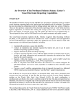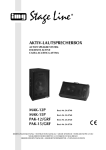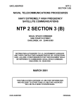
1
U.S. Coast Guard Research and Development Center
1082 Shennecossett Road, Groton, CT 06340-6096
Report No.
ORBCOMM TEST & EVALUATION
FINAL REPORT
NOVEMBER 1999
Distribution limited to U.S. Coast Guard only. Other requests shall be referred to the
U.S. Coast Guard Research and Development Center, Groton, CT 06340-6096.
Prepared for:
U.S. Dept of Transportation
United States Coast Guard
Office of Communications Systems (G-SCT)
Washington, DC 20593-0001
N O T I C E
This document is disseminated under the sponsorship of the
Department of Transportation in the interest of information
exchange. The United States Government assumes no liability for
its contents or use thereof.
The United States Government does not endorse products or
manufacturers.
Trade or manufacturers’ names appear herein
solely because they are considered essential to the object of this
report.
This report does not constitute a standard, specification, or
regulation.
Marc B. Mandler, Ph.D.
Technical Director
United States Coast Guard
Research & Development Center
1082 Shennecossett Road
Groton, CT 06340-6096
ii
Technical Report Documentation Page
1. Report No.
4.
2. Government Accession Number
Title and Subtitle
3. Recipient’s Catalog No.
5. Report Date
November 1999
Orbcomm Test and Evaluation
6. Performing Organization Code
Project No. 9250.7
7. Author(s)
8. Performing Organization Report No.
RDC-271-99
Amy B. Grable
9. Performing Organization Name and Address
10. Work Unit No. (TRAIS)
U.S. Coast Guard
Research and Development Center
1082 Shennecossett Road
Groton, CT 06340-6096
11. Contract or Grant No.
12. Sponsoring Organization Name and Address
13. Type of Report & Period Covered
Final Report
14. Sponsoring Agency Code
U.S. Department of Transportation
United States Coast Guard
Office of Communications Systems
Washington, DC 20593-0001
Commandant (G-SCT)
U.S. Coast Guard Headquarters
Washington, DC 20593-0001
15. Supplementary Notes
The R&D Center’s technical point of contact is LTJG Amy B. Grable, 860-441-2671, email: [email protected]
16. Abstract (MAXIMUM 200 WORDS)
The Orbcomm Low-Earth-Orbit (LEO) satellite communications (SATCOM) system was tested and evaluated at the U.S. Coast
Guard R&D Center as part of the ongoing Mobile Communications Infrastructure project. The objective of the project is to
investigate new and emerging SATCOM systems that may satisfy the Coast Guard’s rapidly increasing communications
requirements.
Orbcomm is a low-cost data-only system used for monitoring remote equipment, tracking mobile assets, and sending/receiving
short messages. After initial testing in the R&D Center’s Advanced Communications Laboratory, the system was installed aboard
three 110-foot coastal patrol boats, two HH-60 Jayhawk helicopters and one HC-130 Hercules fixed-wing aircraft.
The system is very cost-effective for automatic position-reporting and short messaging; however, current pricing schemes render
the system cost-prohibitive for longer messages. These pricing schemes are charging $0.01 per character over and above the
monthly access fee and flat message rate.
It is important to keep in mind that although Orbcomm is touted as a “global” system, a mobile user needs both a satellite and an
earth station to send and receive data in normal operation. Since there are no Orbcomm earth stations near Hawaii, Alaska,
Guam, etc, the system will not work in these areas.
17. Key Words
18. Distribution Statement
Orbcomm, SATCOM, Data Communications, Automated
Position-Reporting
Distribution limited to U.S. Coast Guard only. Other requests
shall be referred to the U.S. Coast Guard Research and
Development Center, Groton, CT 06340-6096.
19. Security Class (This Report)
20. Security Class (This Page)
UNCLASSIFIED
UNCLASSIFIED
iii
21. No of Pages
22. Price
iv
EXECUTIVE SUMMARY
The Coast Guard’s mobile communications requirements are increasing at such a rate that they
will exceed capabilities currently provided by High Frequency (HF), Department of Defense
(DOD) military satellite (MILSATCOM) and Inmarsat systems. Furthermore, existing systems
are outdated and expensive to maintain. Commercial mobile satellite communications
(SATCOM) systems are a logical choice to meet the Coast Guard’s expanding communications
requirements while reducing investment in infrastructure.
There are many different commercial SATCOM companies entering the market. Not all of these
companies will succeed. The R&D Center’s Advanced Communications Technology team is
investigating and evaluating these systems as part of its Mobile Communications Infrastructure
project. The objective of the project is to identify the systems that will most effectively meet the
Coast Guard’s communications requirements at the lowest cost.
The R&D Center produced the report entitled “Technology Assessment of Mobile Satellite
System Alternatives” (Johnson, et al., 1998). This report provided an overview of all potential
new and emerging commercial SATCOM systems. In May 1998, the “Mobile Communications
Requirements” report was delivered, detailing the specific functional requirements for
communications systems aboard various Coast Guard platforms. As individual systems are
tested and evaluated, the results are documented in a test and evaluation report. Such reports
have been published for the American Mobile Satellite System (AMSC), BOATRACS, and
Inmarsat Mini-M systems. This report describes the Orbcomm system evaluation. Currently,
“Mobile Communications Cost Benefit Analysis,” “Mobile Communications Security Analysis,”
and “Comparison of Mobile Satellite System Alternatives to Coast Guard Communications
Requirements” reports are being written. Future systems to be evaluated include Iridium,
Globalstar and ICO. Additionally, an updated version of the “Technology Assessment of Mobile
Satellite System Alternatives” report will be produced in order to keep up with the dynamic
mobile SATCOM marketplace.
Orbcomm is a low-cost, data-only SATCOM system designed for monitoring remote equipment,
tracking mobile assets and sending and receiving short messages. The transceivers are relatively
small, inexpensive and low power. The same transceiver can be used across all platforms as long
as an appropriate VHF antenna is provided. Service can be purchased through any number of
Value Added Resellers (VARs). There is a small charge for monthly service, similar to what you
would pay for cellular service. Position reports can be sent automatically to a predetermined
e-mail account at a cost of approximately $0.25 each. Messages cost about $0.35 each plus an
additional $0.01 per character. The “penny-per-character” pricing scheme is cost-prohibitive for
long messages, but reasonable for short messages. The system is not intended for sending
attachments.
v
In summary, Orbcomm has the potential to meet some but not all of the Coast Guard’s
communications requirements. The feature with the most value to the Coast Guard is probably
the automatic position reporting. The position report interval can be set up ahead of time so that
no user interface is required to track mobile units engaged in Coast Guard operations. The
system is also ideal for sending short messages to and from mobile units. It is inexpensive and
simple enough to be used in conjunction with or as a backup to another SATCOM system, which
could be used for sending longer messages and/or providing voice capability.
Orbcomm is the only system of its kind available commercially today. Most of the other
commercial SATCOM systems on the market are designed for voice, and are therefore more
complex and expensive. Although some of these systems will offer data as well, a dial-up
connection billed by the minute is usually required, making short messages impractical. For
these reasons, Orbcomm should be considered as a significant element of the Coast Guard’s
future communications architecture.
vi
TABLE OF CONTENTS
EXECUTIVE SUMMARY........................................................................................................... v
INTRODUCTION......................................................................................................................... 1
ORBCOMM SYSTEM ................................................................................................................. 1
SPACE SEGMENT .............................................................................................................................. 2
GROUND SEGMENT........................................................................................................................... 3
GATEWAY EARTH STATION .................................................................................................................................. 3
GATEWAY CONTROL CENTER .............................................................................................................................. 3
NETWORK CONTROL CENTER .......................................................................................................... 3
USER SEGMENT ................................................................................................................................ 4
SENDING A MESSAGE ....................................................................................................................... 4
SYSTEM TEST AND EVALUATION ....................................................................................... 5
THE STELLAR EL2000G .................................................................................................................. 5
SAT-EX .......................................................................................................................................... 11
PATROL BOAT INSTALLATIONS ...................................................................................................... 11
HC-130 INSTALLATIONS ................................................................................................................ 13
HH-60 INSTALLATIONS .................................................................................................................. 16
SYSTEM PERFORMANCE...................................................................................................... 20
COVERAGE ..................................................................................................................................... 20
AVAILABILITY ................................................................................................................................ 25
RELIABILITY................................................................................................................................... 26
ACCURACY..................................................................................................................................... 26
INTEROPERABILITY......................................................................................................................... 27
BANDWIDTH ................................................................................................................................... 27
LATENCY........................................................................................................................................ 27
EASE OF USE .................................................................................................................................. 30
COST .............................................................................................................................................. 30
SECURITY ....................................................................................................................................... 31
CONCLUSIONS ......................................................................................................................... 32
RECOMMENDATIONS ............................................................................................................ 33
REFERENCES ............................................................................................................................ 34
APPENDIX A - ORBCOM GROUND EARTH STATION (GES) LOCATIONS.............A-1
APPENDIX B - AVIATION ANTENNA COMPARISONS TO MAXRAD ....................... B-1
APPENDIX C - COVERAGE DURATION AND REVISIT TIME GRAPHS...................C-1
APPENDIX D - PATROL BOAT ORBCOMM USAGE COSTS........................................D-1
vii
LIST OF ILLUSTRATIONS
FIGURE 1
FIGURE 2
FIGURE 3
FIGURE 4
FIGURE 5
FIGURE 6
FIGURE 7
FIGURE 8
FIGURE 9
FIGURE 10
FIGURE 11
FIGURE 12
FIGURE 13
FIGURE 14
FIGURE 15
FIGURE 16
FIGURE 17
FIGURE 18
FIGURE 19
FIGURE 20
FIGURE 21
FIGURE 22
FIGURE 23
FIGURE 24
FIGURE 25
FIGURE 26
FIGURE 27
FIGURE 28
FIGURE 29
FIGURE 30
FIGURE 31
FIGURE 32
FIGURE 33
FIGURE B-1
FIGURE B-2
FIGURE B-3
FIGURE B-4
ORBCOMM SATELLITE CONSTELLATION AS OF OCTOBER 1999....................... 2
ORBCOMM SATELLITE CONSTELLATION AS OF OCTOBER 1999....................... 3
ORBCOMM MESSAGE PROCESS FLOW . ………………………………………4
ORBCOMM TEST-BED SYSTEM ARCHITECTURE ……………………………..5
COMPONENTS OF STELLAR EL2000G ……………………………………….6
STELCOMM STATUS WINDOW . ……………………………………………….7
STELCOMM PARAMETERS WINDOW …………………………………………8
TELCOMM MESSAGES WINDOW .. …………………………………………....9
TELCOMM APPLICATION WINDOW: MONITORING ………………………….10
STELCOMM APPLICATION WINDOW: POSITION REPORT ............................... 10
PATROL BOAT ORBCOMM TRANCEIVER MOUNTED ABOVE CHART TABLE ...... 12
PATROL BOAT LAPTOP COMPUTER LOCATED ON BRIDGE ............... …………12
PATROL BOAT VHF MAXRAD ANTENNA …………………………………12
PATROL BOAT GPS ANTENNA MOUNTED ON SPEAKER…………………… 13
HC-130 VHF ANTENNA……………………………………………………14
HC-130 VHF ANTENNA…………………………………………………... 14
HC-130 ORBCOMM TRANCEIVER MOUNTED BELOW RADIO TABLE………….15
HC-130 LAPTOP COMPUTER ON RADIO TABLE …………………………..….15
HC-130 GPS SPLITTER MOUNTED BELOW RADIO TABLE……………………16
HH-60 ORBCOMM TRANSCEIVER MOUNTED ON
EXTENDED AVIONICS RACK..................................... …..…………….….…...17
HH-60 VHF ANTENNA…………………………………………..…………18
HH-60 ORBCOMM GPS ANTENNA .. ……………………………..…………18
HH-60 KNEEBOARD WITH MOUNTED LAPTOP COMPUTER . ………………….19
HH-60 BREAKOUT BOX MOUNTED PORT SIDE OF AIRCRAFT .......... .……...19
LENGTH OF SATELLITE PASS DEPENDS UPON DISTANCE FROM
CENTER OF FOOTPRINT....... …………………………..…………..……...…20
LENGTH OF USER-SATELLITE-GATEWAY “CHAIN” DURATION…... ……….…21
POST-D-PLANE ACCESS TO CURACAO GES…………………………….…..23
POST-D-PLANE MAXIMUM GAPS IN ACCESS TO CURACAO GES …………...23
POST-EQUATORIAL-PLANE ACCESS TO CURACAO GES…………………….24
POST-EQUATORIAL-PLANE MAXIMUM GAPS IN ACCESS
TO CURACAO GES ............................................. …………………………...24
CONSEQUENCES OF SATELLITE FAILURE ...... ………………………….25
229-BYTE MESSAGE LATENCY…………………………… ……………….28
1405-BYTE MESSAGE LATENCY……………………… …………………...29
HC-130 618 SYSTEM ANTENNA VS MAXRAD ............................................. B-1
HC-130 ELT ANTENNA VS MAXRAD ......................................................... B-1
HH-60 ELT ANTENNA VS MAXRAD .................................. …………….....B-2
ALLEN 574 ANTENNA VS MAXRAD ................................... …………….….B-2
viii
LIST OF ILLUSTRATIONS (CONT’D)
FIGURE C-1
FIGURE C-2
FIGURE C-3
FIGURE C-4
FIGURE C-5
FIGURE C-6
FIGURE D-1
FIGURE D-2
FIGURE D-3
COVERAGE DURATION: SAN DIEGO........................................ ……………..C-1
REVISIT TIME: SAN DIEGO ................................................ …………..….…C-1
COVERAGE DURATION: CABO SAN LUCAS ................................................... C-2
REVISIT TIME: CABO SAN LUCAS …………………………………………..C-2
COVERAGE DURATION: GUATEMALA ........................................................... C-3
REVISIT TIME: GUATEMALA ......................................................................... C-3
CGC LONG ISLAND COST SUMMARY ............ ……………………..…....D-1
CGC EDISTO ORBCOMM COST SUMMARY …………………………..…..D-2
CGC TYBEE ORBCOMM COST SUMMARY ……………………...……..…D-3
LIST OF TABLES
TABLE 1
TABLE 2
TABLE A-1
COVERAGE DURATION FOR CGC TYBEE STK SIMULATION, 12OCT 99 ..... 22
REVISIT TIME FOR CGC TYBEE STK SIMULATION, 12OCT 99 ................... 22
ORBCOMM GROUND EARTH STATION (GES) LOCATIONS …………………A-1
ix
x
INTRODUCTION
The objective of the R&D Center’s Mobile Communications Infrastructure Project is to
investigate and evaluate commercial satellite solutions that may meet the Coast Guard’s current
and future communications requirements. The solution will not likely be a single system, but
rather a combination of satellite, HF and VHF systems. It must be accurate, robust,
interoperable, secure and timely. Although MILSATCOM will continue to be a DOD
requirement, Coast Guard communications can be preempted by higher priority DOD
requirements. Commercial SATCOM bridges the gap between MILSATCOM and complete loss
of satellite communication service and may provide substantial cost savings.
At least 40 different commercial SATCOM companies will be offering service in the next five
years. These systems will differ in both physical attributes and functional capabilities. The goal
is to identify the systems that will most effectively meet the specific operational requirements of
the Coast Guard at the lowest cost. The first step taken by the R&D Center as part of the Mobile
Communications Infrastructure Project was to identify all existing and emerging SATCOM
systems in the “Technology Assessment of Mobile Satellite System Alternatives” report. Next,
the “Coast Guard’s Mobile Communications Requirements” report (Anteon, 1998) was written
to collect and document specific operational requirements of different missions and platforms
within the organization. The R&D Center is in the process of testing and evaluating several of
the candidate systems documented in the “Technology Assessment of Mobile Satellite System
Alternatives” report to determine if they meet the criteria defined in the “Coast Guard’s Mobile
Communications Requirements” report.
The purpose of this evaluation was to determine whether a satellite data communications system
like Orbcomm could benefit Coast Guard communications by improving performance, meeting
requirements not currently being met, and/or reducing cost. Specific system evaluation
parameters included coverage, availability, reliability, accuracy, interoperability, bandwidth,
latency, ease of use, and cost. Some testing was conducted in the Advanced Communications
Laboratory at the R&D Center, and some was conducted aboard Coast Guard boats and aircraft.
ORBCOMM SYSTEM
ORBCOMM is a low-earth-orbit (LEO), data-only satellite communications system owned by a
partnership of Orbital Sciences Corporation and Teleglobe Inc., of Canada. The FCC granted the
company a commercial license in October of 1994. Their system is capable of sending and
receiving short text messages, monitoring remote equipment , and tracking mobile units.
Automatic position reporting is accomplished using embedded GPS or an inherent Doppler
position calculation. The user terminal, or subscriber communicator (SC), transmits in the 148150 MHz frequency range at 2400 bps and receives in the 137-138 MHz frequency range at 4800
bps. Like any SATCOM system, ORBCOMM is made up of three segments: space, ground,
and user.
1
Space Segment
The space segment is the constellation of satellites. ORBCOMM is currently made up of 28
Microstar satellites with a launch of seven more expected in early November and another eight in
late 2000. The main function of these satellites is to complete the link between a mobile user
and an earth station, or gateway. ORBCOMM is a bent-pipe system so both the user and a
gateway must be within the footprint of the same satellite in order to communicate in “real time.”
There is no inter-satellite communication; however, if no gateway is available, a satellite can
store data in its memory until it passes over a gateway. A message sent using this “store-andforward” process is called a Globalgram. Globalgrams must be pre-designated by the user, are
limited to 128 characters, and cost more than standard messages.
The current constellation of satellites consists of five separate orbital planes: A, B, C, F, and G.
The A, B, and C planes each contain eight satellites and are inclined 45 degrees at an altitude of
775 km. The D plane, which is scheduled for launch in early November, will consist of seven
satellites and will also be inclined 45 degrees at an altitude of 775 km. The F and G planes each
consist of two satellites in a near-polar orbit at an altitude of 825 km. These two planes are
inclined 70 degrees and 108 degrees, respectively. The planned launch in 2000 will put eight
more satellites in an equatorial orbit (zero degrees) at an altitude of 800 km,b bringing the total
constellation to 43.
Figures 1 and 2 below depict the current constellation. The A plane is shown in blue, the B
plane is orange, the C plane is green, the F plane is magenta, and the G plane is red.
Figure 1. Orbcomm Satellite Constellation as of October 1999
2
Figure 2. Orbcomm Satellite Constellation as of October 1999
Ground Segment
The ground segment consists of Gateway Earth Stations (GESs), Gateway Control Centers
(GCCs), and the Network Control Center (NCC).
Gateway Earth Station
The function of the GES is to link the ground segment with the space segment. They are located
all over the world, including four in the United States: Arizona, Washington, Georgia, and New
York. A complete listing of all locations can be found in Appendix A. The GES receives orbital
information from the GCC and tracks satellites as they cross the sky using a steerable high-gain
VHF antenna. There is a backup antenna at every GES for redundancy. User data are passed
between the GES and the satellites at 56.7 kbps.
Gateway Control Center
The GCC is the interface between Orbcomm and standard terrestrial-based networks. Orbcomm
can support a wide-range of communication protocols including X.400, X.25, leased line, dial-up
modem, public or private data networks, and e-mail networks. In general, any standard e-mail
address ([email protected]) is all that is needed to communicate with an Orbcomm
device. The conversion from standard Simple Mail Transfer Protocol (SMTP) to Orbcomm’s
proprietary messaging language is transparent to the end-user.
Network Control Center
The NCC is located in Dulles, VA, and serves as the GCC for the United States. Its main
function is to manage the Orbcomm network elements and the Unites States gateways through
telemetry monitoring, system commanding and mission system analysis. Orbcomm-certified
3
controllers are on duty at the NCC 24 hours a day, and seven days a week to ensure satellites are
functioning properly.
User Segment
The user segment is made up of various types of subscriber communicators (SCs) including
hand-held devices for personal messaging, fixed units for remote monitoring, and mobile units
for tracking applications. Manufacturers include Magellan, Panasonic, Stellar and ScientificAtlanta. The terminals offer a wide range of capabilities and cost anywhere from $500-$2000.
All operate in the VHF frequency band, transmitting at 2400 bps and receiving at 4800 bps.
Sending a Message
Figure 3 shows how a message is sent using Orbcomm. The message sent from an SC is
received at the satellite and relayed down to one of the GESs that connects the Orbcomm ground
system with the satellites. The GES then relays the message via satellite link or dedicated
terrestrial line to the NCC. The NCC routes the message to the final destination via e-mail,
dedicated telephone line or facsimile. Messages and data sent to an SC can be initiated from
any computer using common e-mail systems such as Microsoft Outlook, Eudora, or cc:Mail.
The NCC or GCC transmits the information in the reverse direction to terminate at the SC.
Figure 3. Orbcomm message process flow
4
SYSTEM TEST AND EVALUATION
The system was initially tested in the Advanced Communications Laboratory at the R&D Center.
Field-testing was conducted by installing the system aboard three 110-ft Island Class patrol
boats, two HH-60 Jayhawk helicopters, and one HC-130 Hercules fixed wing airplane. Figure 4
depicts the test-bed system architecture.
Stellar EL2000G
Laptop
Orbcomm Gateway
SWIII
Network Control Center
PSTN
RDC Lab
Figure 4. Orbcomm test-bed system architecture
The Stellar EL2000G
At the time of initial testing, there were very few subscriber communicators available on the
market. The Stellar EL2000G data communicator was chosen because it was the furthest along
in development and production. This unit is simply an intelligent wireless modem designed for
the Orbcomm system. Features include continuous remote operation, data logging, messaging,
tracking, sensor monitoring, position reporting, and power management.
5
The EL-2000G is compact and lightweight, but extremely rugged. The box consists of a case,
battery, charger, RS-232 port, analog and digital I/O, and embedded GPS. (The EL2000 is the
same piece of equipment without the GPS.) The 12-volt DC, 0.8 amp-hour, rechargeable, leadacid battery will power the unit for up to six hours in standby operation and up to three weeks in
sleep mode. Uninterrupted operation is provided by the built-in battery charger, which will
accept anywhere from 9 to 36 volts DC.
EL-2000G Block Diagram
VHF Antenna
9-36 VDC
RF
BOARD
DC C&S I/Q
RX
I/Q
TX
SIGNAL
PROCESSING
BOARD
GPS Antenna
LEAD
LEAD ACID
ACID
RECHARGEABLE
RECHARGEABLE
BATTERY
BATTERY
Serial Interface
Discrete I/O
GPS
GPS
BOARD
BOARD
(EL-2000G)
(EL-2000G)
Figure 5. Components of Stellar EL2000G
The EL-2000G is designed to interface with personal computers, sensors, alarms, and other
equipment via the standard I/O cable. We used Pentium laptop computers running Microsoft’s
Windows 95 operating system and StelComm software to control the unit. StelComm is
available free of charge at the manufacturer’s web-site and is used to view status, set parameters,
send and receive messages, and configure applications.
The Status window shown in figure 6 shows the current state of communications between the
EL-2000G and the Orbcomm system. Details include: UTC time and date as reported by GPS,
number of downlink packet errors, total number of gateways connected to the satellite in view,
number of terminated messages in the unit’s memory queue, number of originated messages in
the unit’s memory queue, LED indicator showing whether or not a satellite is in view, ID number
of the satellite in view and GPS Position.
6
Figure 6. StelComm Status window
The Parameters window shown in figure 7 enables the user to configure settings and access
debug data. From here the user can: import parameters from a file, update software or firmware,
set a password or PIN code, set preferred gateway for searching and sending messages, set buffer
sizes, display the unit’s serial number, set minimum battery voltage level allowed before
shutdown, determine message queuing operation, enable or disable GPS, set interval between
sequential GPS measurements, set parameters specific to a position report, view and store to a
file real-time details of unit operation, set speed-dial numbers for default reports and messages,
define priority used to send default messages, specify which features can be modified remotely,
and change default units for date, temperature, distance, etc.
7
Figure 7. StelComm Parameters window
The Messages window shown in figure 8 allows the user to compose, send, and receive
messages, reports, and Globalgrams. Sending and receiving messages using StelComm is very
straightforward. The subject line, message priority, acknowledgement level, message body type,
and recipient address are entered in the Message Details screen. Although there is no address
book capability, there is an option to pre-program up to nine “speed-dial” e-mail addresses,
which can be quickly selected from the Indicator pull-down box. The user must hit the Add
button after each address in order to send the message to multiple recipients. There is a sevenrecipient maximum per message. The text of the message is typed in the Message Body screen.
The system does not currently support the sending of message attachments. At the bottom of the
Message Body screen, the user must hit the Send button when the message is complete.
Messages will be listed on the appropriate Inbox and Outbox screens until they are either deleted
or sent.
8
Figure 8. StelComm Messages window
The Application window allows the user to program the SC parameters for several built-in
autonomous applications. The SC can be programmed to monitor digital and analog inputs,
determine the unit position, time, date, power-save logic, external power indication and more.
After the SC is programmed, it will operate automatically, performing the preprogrammed
functions.
The Monitoring feature shown in figure 9 was used to automatically generate and collect data for
our system evaluation. This feature allows the user to configure an application for monitoring
internal system parameters as well as external sensors and alarms. The standard I/O cable will
accept up to six digital inputs and up to three analog inputs.
9
Figure 9. StelComm Application window: Monitoring
The Position Report feature is used to send six-byte position reports at regular intervals. This
application runs only when a satellite is in view. A new position report will not be queued until
the previous Position Report is transmitted. The position will be derived from the GPS input if
available. Otherwise, the unit will use a Doppler calculation to estimate position. The unit can
also be programmed to transmit a fixed position if the SC is not mobile. The position report
interval (in seconds) is entered by the user as shown in figure 10.
Figure 10. StelComm Application window: Position Report
10
Sat-Ex
Although StelComm was our primary messaging application, we also successfully used
Microsoft Outlook as an e-mail client. We tested the beta version of a software connector called
Sat-Ex, which allows the user of any Windows 95 or Windows 98 PC to send and receive
messages over the ORBCOMM system. Outlook was used as the e-mail application, but
StelComm was still required for viewing status, setting parameters and configuring applications
on the EL-2000G. Outlook offers many features not available in StelComm such as spell
checking, folder support, auto archiving, multiple user profiles and address book. Furthermore,
users required minimal training since most had used Outlook on the Coast Guard’s Standard
Workstation III (SWIII).
The beta version of Sat-Ex (v 1.0.050.2) we tested had some obvious inadequacies. It does not
support Rich Text Format (RTF), which is what most e-mail clients use. If an RTF message is
received by a unit running Microsoft Outlook via Sat-Ex, the message body will be unreadable.
The message would have to be read using StelComm, which has the capability of converting
RTF messages to plain text. Another disadvantage is that Sat-Ex and StelComm both utilize the
same communications port on the laptop to interface with the transceiver, so both applications
cannot be running at the same time. Therefore, the user cannot use StelComm to monitor the
system status or set parameters while running Sat-Ex. The manufacturer of Sat-Ex claims that
future versions will support RTF as well as data compression and encryption.
Patrol Boat Installations
The Orbcomm system was installed on CGC TYBEE, CGC EDISTO and CGC LONG ISLAND,
all homeported in San Diego, CA. The installation was coordinated with support from the 11th
Coast Guard District Patrol Boat manager and the Electronics Systems Support Detachment San
Diego. The Stellar EL2000G was mounted above the chart table on the bridge (figure 11). A
laptop computer running StelComm was located on the chart table when in use (figure 12). A
MAXRAD MFB VHF Series omni-directional fiberglass antenna was mounted on the mast
ladder for the RF interface (figure 13). The magnetic GPS antenna was mounted on the ship’s
speaker (figure 14). DC power was provided from the boat’s internal power supply.
11
Figure 11. Patrol boat Orbcomm transceiver mounted above chart table
Figure 12. Patrol boat laptop computer located on bridge
Figure 13. Patrol boat VHF MAXRAD antenna
12
Figure 14. Patrol Boat GPS antenna mounted on speaker
HC-130 Installations
The Orbcomm system was installed on one HC-130 Hercules class aircraft at U.S. Coast Guard
Air Station Sacramento. The installation was coordinated with the support of the Office of
Aeronautical Engineering (G-SEA) and the U.S. Coast Guard Aircraft Repair and Supply Center
(AR&SC). The Electromagnetic Compatibility (EMC)/Safety of Flight Testing (SOFT) was
conducted by NAVAIRWARCEN, Patuxent River, MD.
Unlike other SATCOM systems, there is not a transceiver specifically manufactured for the
aviation community. Therefore, we were able to use the Stellar EL2000G SC for the aircraft
testing as well as the shipboard testing. Several tests were conducted in the Advanced Comms
Lab to find a VHF antenna comparable to the MAXRAD antenna and suitable for aviation. In
order to determine the best candidate, two separate systems were set up in the lab. The systems
were identical with the exception of the RF interface--one of the systems used the MAXRAD
antenna while the other used one of three candidate aviation antennas. The two systems were
monitored to determine how often they had access to a satellite. Two of the three candidate
antennas are already used on the HC-130 for other VHF applications. These were the 618
System Antenna and the Emergency Locator Transmitter antenna; they were borrowed from
AR&SC for testing purposes. One other antenna, which was recommended at the 1998
Orbcomm Users Conference, was bought commercially. It is a blade antenna manufactured by
Antenna Specialists Division of Allen Telecom, Inc. (Model ASP-574ORB). The 618 System
antenna proved to have the best performance. Graphical results of the antenna comparisons can
be found in Appendix B.
The VHF antenna was mounted on top of the aircraft toward the front (figures 15 and 16). The
SC was mounted below the radioman’s table in the cockpit (figure 17). The laptop computer
running StelComm was operated from the radioman’s table (figure 18). The GPS interface was
“split” from the aircraft’s existing GPS system (figure 19).
13
Figure 15. HC-130 VHF Antenna
Figure 16. HC-130 VHF Antenna
14
Figure 17. HC-130 Orbcomm transceiver mounted below radio table
Figure 18. HC-130 Laptop computer on radio table
15
Figure 19.
HC-130 GPS splitter mounted below radio table
HH-60 Installations
The Orbcomm system was installed on two HH-60 Jayhawk helicopters at U.S. Coast Guard Air
Station San Diego. The installations were conducted with the support of the Office of
Aeronautical Engineering (G-SEA) and the U.S. Coast Guard Aircraft Repair and Supply Center
(AR&SC). The Electromagnetic Compatibility (EMC)/Safety of Flight Testing (SOFT) was
conducted by NAVAIRWARCEN, Patuxent River, MD.
The Stellar EL2000G was mounted in the extended avionics rack (figure 20). The HH-60
Emergency Locator Transmitter (ELT) antenna was tested in the Advanced Comms Lab for use
as the RF interface, but performed poorly. Results of this test can be found in Appendix B. The
DMC-63-3/A VHF-FM antenna was recommended by AR&SC and resulted in satisfactory
performance (lab testing results are not available). The antenna was mounted on the auxiliary
door on top of the aircraft (figure 21) so that the door could be swapped out for an unaltered one
at the end of the testing period. The GPS interface was provided by a small patch antenna, which
was mounted on a bracket in the cockpit over the co-pilot’s head (figure 22).
16
The R&D Center affixed a small laptop computer to a kneeboard (figure 23) in order to make it
easy for an aircrewman to operate StelComm. A breakout box (figure 24) was fabricated to
provide a power interface, data interface, and control mechanism for the SC and the laptop
computer. The power interface consisted of a single 5-Amp circuit breaker in the avionics rack.
The aircraft’s 28Vdc power was distributed to the EL2000G and to the breakout box. At the
breakout box, the power was fused to protect the aircraft from a failure of the Orbcomm system.
From the breakout box, the power was distributed to the aircrewman’s kneeboard. Internal to the
kneeboard, the power was converted to 15Vdc and supplied to the laptop computer. The data
interface was established between the EL2000G’s serial port and the laptop computer’s serial
port via the breakout box. A control mechanism was established between the breakout box and
the EL2000G in order to turn the unit on or off.
Figure 20. HH-60 Orbcomm transceiver mounted on extended avionics rack
17
Figure 21. HH-60 VHF antenna
Figure 22. HH-60 Orbcomm GPS antenna
18
Figure 23. HH-60 Kneeboard with mounted laptop computer
Figure 24. HH-60 Breakout box mounted port side of aircraft
19
SYSTEM PERFORMANCE
Coverage
Coverage is the geographic area in which a mobile user has access to the satellite system.
Although the 28 Orbcomm satellites currently in orbit provide global coverage, they do not
provide simultaneous global coverage. In other words, not every inch of the Earth’s surface is in
the footprint of a satellite at all times. It takes approximately 1.5 hours for each satellite to orbit
the Earth. Since the Earth is also rotating (at a slower rate), each time the satellite orbits, it’s
path will shift with respect to the Earth’s surface. So a user in a given location will be covered
by several different, possibly overlapping, satellite footprints during the course of a day.
Coverage depends on many factors. For example, if a satellite passes directly overhead, a user
will experience the full diameter of the satellite’s footprint. On the other hand, if the satellite
does not pass directly overhead, the user will benefit for a shorter time-span. Figure 25
illustrates this point.
Satellite footprint
Figure 25. Length of satellite pass depends upon distance from center of footprint
It is important to remember; however, that a user needs a gateway as well as a satellite to send
messages in the “real-time” mode. For the purposes of this study, coverage will be defined as
the amount of time the user has both a satellite and a gateway in view. In figure 26, the shaded
gray area depicts actual coverage duration. The circles represent the footprint of a satellite as it
moves from left to right. In step 1, the gateway is just coming into the satellite footprint. In step
2, the user is just coming into the satellite footprint. Step 3 shows the gateway leaving the
satellite’s footprint, and step 4 shows the user leaving it. The only time the user is able to send a
message in real-time is during the intersection of steps 2 and 3.
20
Figure 26. Length of user-satellite-gateway “chain” duration
A software package called Satellite ToolKit (STK) manufactured by Analytical Graphics Inc.
(AGI) was used to predict coverage. STK can be used to create simulations, or scenarios,
involving objects such as satellites, earth stations, targets, and more. Element sets containing a
satellite’s actual orbital data can be downloaded from AGI’s web-site. STK plugs these data
files into high-precision propagation algorithms to constantly update the satellite’s predicted
location, thereby “animating” the scenario. The element sets are updated weekly at AGI’s web
site. If no actual orbital data is available, satellites can be created and added to a scenario using
STK’s “Orbit Wizard.” This was very important during early stages of testing before Orbcomm
had launched all of its satellites. Because of the incomplete satellite constellation, there were
only a few hours of the day during which testing could be conducted. We were able to take
advantage of the limited coverage time by scheduling our testing according to predicted
availability. The accuracy of the STK simulation was verified by comparing the predicted
coverage by a particular satellite to the actual coverage of that satellite as indicated by the
StelComm status window.
STK consists of a basic software version and various “add-on” modules. The Chains module
was used to group all of the Orbcomm satellites into a constellation. The known gateway
locations were also entered into the scenario and grouped into a constellation. Targets were
entered into the scenario to represent the R&D Center, and all of the field test-bed units. A
“chain” is completed when a target and gateway are both in the footprint of the same satellite. A
completed chain represents coverage for that particular target.
Initial testing indicated that quality of coverage seemed to be consistent regardless of longitude;
however, it was affected significantly with changes in latitude. A scenario was generated to
demonstrate the difference in coverage at three different geographic locations. CGC TYBEE
was used as a target in the scenario. The three locations were:
21
•
•
•
Homeport, San Diego
Cabo San Lucas, Mexico
Guatemala,
32.68 N, 117.23 W
22.24N, 109.23 W
13.92N, 90.78 W
The scenario was run over a 24-hour period for all three locations. The coverage duration and
revisit times were measured. Coverage duration is the amount of time the TYBEE had access to
a complete chain, while revisit time is the length of time TYBEE had to wait between coverage
intervals. The minimum, maximum, average, and total coverage duration and revisit times were
measured. The results are shown below in tables 1 and 2. Graphical results can be found in
Appendix C.
Table 1. Coverage Duration Measurements for CGC TYBEE STK Simulation, 12OCT 99
Coverage Duration (hh:mm:ss)
San Diego
Cabo San Lucas
Guatemala
Minimum
0:00:48
0:00:30
0:00:16
Maximum
0:13:35
0:13:22
0:10:58
Average
0:11:06
0:07:54
0:07:05
Total
20:05:35
14:33:00
9:48:00
Table 2. Revisit Time Measurements for CGC TYBEE STK Simulation, 12OCT 99
Revisit Times (hh:mm:ss)
San Diego
Cabo San Lucas
Guatemala
Minimum
0:00:20
0:00:22
0:00:27
Maximum
0:13:35
0:19:46
2:09:00
Average
0:03:39
0:06:35
0:13:00
Total
3:54:25
9:27:00
14:12:00
The results show that coverage was adequate near San Diego. The longest measured gap in
coverage was 13 minutes. This is acceptable for non-urgent Coast Guard tracking and
messaging. As the cutter moved south in the scenario though, coverage declined drastically.
Near Guatemala the longest gap in coverage was over two hours! Gaps such as this are
unacceptable for most Coast Guard applications. Orbcomm is aware of this deficiency and is
taking steps to improve coverage in the lower latitudes.
In November 1999, Orbcomm plans to launch seven more satellites, which will constitute the
D-plane. This plane will be inclined 45 degrees at an altitude of 775 km. Figure 27 shows
coverage contours near Central America and the northern tip of South America. Orbcomm has a
GES in Curacao, which is represented by the small blue square in the figure. The contour lines
around it represent coverage as a percentage of a 24-hour period. In this graphic, only access to
the Curacao GES is considered even though access to other GESs may have been possible.
Coverage is best close to the GES because there is an increased likelihood of having both a
satellite and GES. Coverage deteriorates as a direct function of an increase in distance from the
GES. The contour lines in figure 28 represent the maximum gap-length in minutes for the same
geographic location and time period.
22
Figure 27. Post-D-plane access to Curacao GES
Figure 28. Post-D-plane maximum gaps in access to Curacao GES (in minutes)
23
Orbcomm also plans to launch eight more satellites into an equatorial plane sometime in late
2000. This plane will be inclined zero degrees at an altitude of 800km. Figures 29 and 30 show
percent access to the Curacao GES and gaps in access to the Curacao GES, respectively. These
graphics show that coverage will greatly improve in the lower latitudes when the Orbcomm
satellite constellation is complete. Therefore, it is probable that Orbcomm will provide an
acceptable level of service in most areas the Coast Guard operates.
Figure 29. Post-equatorial-plane access to Curacao GES
Figure 30. Post-equatorial-plane maximum gaps in access to Curacao GES (in minutes)
24
Availability
Availability is the amount of time on any given day that the system is available for use. This
parameter should not be confused with coverage. System availability could be affected when:
• traffic exceeds the capacity of the system
• a satellite or GES fails
• a satellite is removed from service for testing
Although a mobile user may have coverage, the system cannot be used if either the satellite or
GES providing that coverage is unavailable. Unlike a GEO system where each satellite covers a
third of the globe, LEO satellites continuously move with respect to the Earth’s surface. In the
case of a GEO satellite failure, an enormous amount of users would completely lose service,
whereas a LEO satellite failure would result in a temporary loss of service for a small number of
users. According to STK simulations, the average Orbcomm satellite pass is about 14 minutes.
The average gap between satellite passes is about two minutes. (These numbers were
corroborated by actual system testing.) Therefore, if an Orbcomm satellite fails, a user will
experience a maximum gap of 18 minutes before the next healthy satellite in the plane passes
overhead as shown below in figure 31.
Failed Satellite
14 min
14 min
14 min
Satellite Footprint
2 min. gap between
satellite passes
18 min
Figure 31. Consequences of Satellite Failure
Since the same failed satellite will pass over a stationary user several times in a 24-hour period,
the total amount of lost satellite usage will accumulate to approximately 11/2 hours per day if the
satellite is not restored. In actuality, satellites in other planes would be providing simultaneous
coverage for the majority of this time, so the user most likely would not even notice the outage.
Although latency would probably increase slightly, the message would still go out with the next
pass by a healthy satellite.
25
If a GES fails, the consequences would be much more drastic than a single satellite failure.
Coverage would be severely limited in the vicinity of the failed GES. Users would have to rely
on other GES sites, which could be several hundred miles away. For this reason, each Orbcomm
GES site has two fully independent antenna systems with associated RF and control equipment
for complete functional redundancy.
Orbcomm posts status reports on its websites indicating when system components are not
available. On a typical day during our testing, at least one or two satellites were unavailable
causing a minor decrease in coverage. For the most part, Orbcomm maintains a current library
of the status reports so interested users can have an accurate representation of the health of the
constellation.
Reliability
Reliability is a measure of a system’s dependability. Since Orbcomm is a relatively new system,
there were several bugs. Most of the problems we encountered with the system were resolved by
working together with Orbcomm and Stellar technical support personnel. More of these bugs
will be worked out as time goes on.
As explained in the previous section, failure of an Orbcomm satellite user will result in decreased
coverage. If the satellite cannot be restored right away, the other satellites in its plane can be
controlled to spread out in order to cover the gap. If this were to occur, the gaps between
satellite footprints would increase from two minutes to about four minutes. Since Orbcomm
satellites are much less complex than traditional communications satellites, they are relatively
inexpensive to replace. The satellites have a lifetime of approximately five years at which time
they must be replaced anyway.
Each GES site is equipped with two fully independent antenna systems with associated RF and
control equipment. Each antenna has its own separate communications link; this helps ensure
complete functional redundancy.
Although the Stellar EL2000G units are extremely rugged, we did have one failure during
testing. The unit was replaced by the company at no charge.
Accuracy
Accuracy is a measure of the absence of error. In the case of a data system such as Orbcomm,
this simply means that the information is unchanged when transmitted from sender to receiver.
Since Orbcomm employs error checking and error-correcting algorithms, it would be very
unlikely to receive a “garbled” message. If proper acknowledgement is not received for each
packet sent, Orbcomm will simply re-send the information. Results of one year of field testing
verified that there were no reported instances of changed or unreadable messages. The system
can be considered highly accurate.
26
Interoperability
This is a measure of how well the system interfaces or integrates with existing systems.
Orbcomm is able to interface seamlessly with the PSTN in order to send information to or from
any standard Internet address. Anyone with the capability to send e-mail can send a message to
someone with an Orbcomm SC. Orbcomm addresses are of the same format as other Internet
addresses, e.g., [email protected]
The Orbcomm system was also successfully integrated with the First Coast Guard District’s
Operational Web Link (OWL) 2.0 program. OWL 2.0 is a law enforcement application used by
HU-25 Falcon fixed-wing aircraft in the First District, which allows the aircrewman to query an
extensive database of commercial vessels and automatically compose and send sighting reports
to a predefined set of users. This was tested in the Advanced Comms Lab, but not in the field.
If desired, the Coast Guard could run a dedicated line from Orbcomm’s NCC directly to the
Coast Guard e-mail gateway in order to keep official traffic off the Internet. This would increase
the security of our information and prevent delays and bottlenecks often associated with the
Internet.
Bandwidth
Bandwidth is the “width” of a communications channel. Essentially, it is a measure of how
much information can be transferred by the channel. The Orbcomm system is capable of sending
data at 2400 bps and receiving data at 4800 bps. In a packet-switched system like Orbcomm;
however, the bandwidth is not as much of a concern as it would be in a circuit-switched system
where a dial-up connection is established. Users are billed by the size of the message, not the
amount of time it takes to transmit. As long as the transmission time is not unreasonable,
Orbcomm users need not be concerned with the bandwidth.
Latency
Latency is the end-to-end delay of information sent over the system. The time it takes to
physically transmit a message over the satellite channel is negligible compared to other delays.
For example, the message will sit in a queue at the GES, if SC-terminated, or at the SC, if SCoriginated, until the SC has both a satellite and a gateway to link to. Additional delays may be
caused by earth-station switching, network congestion or system failures. For the purposes of
this study, these intermediate delays were not measured individually. Latency was calculated
simply by subtracting the time the originator hit the “send” key from the time the message
arrived in the recipient’s inbox. For consistency, only messages originated at the SC were
considered. Several thousand SC-originated messages were collected over a twelve-month
period for this analysis. Since the uplink from the SC to the satellite (2400 bps) is slower than
the downlink from the satellite to the SC (4800 bps), we were measuring a “worst-case” latency
situation.
In order to remove the end-user from the process, the Monitoring function of StelComm was
used to automatically generate test messages. Readings for date, time, latitude, longitude,
altitude, speed, and heading were taken every two minutes, compiled into the body of a message,
27
and sent to a predefined e-mail address at the R&D Center every ten minutes or every hour. We
had the test-bed units vary between sending the small and large messages in order to test the
latency of different size messages over the system. The messages sent every ten minutes were
229 bytes, while the messages sent every hour were 1405 bytes.
A spreadsheet was set up to keep track of these test-message latencies. The queue time was
extracted from the “sent” time-stamp on the message itself, while the “received” time was
obtained from the R&D Center’s server mail log. These times were subtracted to determine the
end-to-end latency.
Time (hh:mm:ss)
Latency of Monitoring MSGs sent from Tybee SC once every 10 minutes
0:15:00
0:14:30
0:14:00
0:13:30
0:13:00
0:12:30
0:12:00
0:11:30
0:11:00
0:10:30
0:10:00
0:09:30
0:09:00
0:08:30
0:08:00
0:07:30
0:07:00
0:06:30
0:06:00
0:05:30
0:05:00
0:04:30
0:04:00
0:03:30
0:03:00
0:02:30
0:02:00
0:01:30
0:01:00
0:00:30
0:00:00
1
8
15
22
29
36
43
50
57
64
71
78
85
92
99
106
113
120
127
134
141
Sample
Latency
Average
Figure 32. 229-Byte message latency
Figure 32 shows the latencies of the 229-byte test messages sent from the CGC TYBEE over a
24- hour period. Messages were sent every ten minutes, so a total of 144 messages were
evaluated. The solid line represents the individual latencies, while the dotted line is a cumulative
average. The minimum latency recorded during this period was 36 seconds, while the maximum
was 14 minutes and 38 seconds. The average latency for this period was 2 minutes and 18
seconds.
28
Time (hh:mm:ss)
Latency of Monitoring MSGs sent from Tybee SC once every 60 minutes
0:33:00
0:32:00
0:31:00
0:30:00
0:29:00
0:28:00
0:27:00
0:26:00
0:25:00
0:24:00
0:23:00
0:22:00
0:21:00
0:20:00
0:19:00
0:18:00
0:17:00
0:16:00
0:15:00
0:14:00
0:13:00
0:12:00
0:11:00
0:10:00
0:09:00
0:08:00
0:07:00
0:06:00
0:05:00
0:04:00
0:03:00
0:02:00
0:01:00
0:00:00
1
2
3
4
5
6
7
8
9
10 11 12 13 14 15 16 17 18 19 20 21 22 23 24 25 26 27 28 29 30 31
Sample
Latency
Average
Figure 33. 1405-byte message latencies
Figure 33 shows the latencies of the 1405-byte test messages sent from the CGC TYBEE over a
31-hour period. The test messages were sent every hour for a total of 31 messages. The
minimum latency measured during this period was 2 minutes and 11 seconds, while the
maximum was 31 minutes and 18 seconds. The average latency for this period was 9 minutes
and 38 seconds.
Note: Although the above results are specific to CGC TYBEE, they are representative of the
results obtained at the other five units.
During early latency testing, we noticed that some of the test messages were lost completely.
Lost messages were detected by examining the queue times in the spreadsheet. If the interval
was greater than ten minutes for 229-byte test messages or one hour for 1405-byte test messages,
we knew that a message had been lost. After extensive troubleshooting, we were able to solve
the problem by manually adjusting the frequency-offset potentiometer inside the Stellar
EL2000G. The manufacturer has since created a software patch so that manual intervention is no
longer necessary. After upgrading our software, we did not lose any more test messages.
29
Another problem we experienced during testing was duplicate messages. If an SC does not
receive final acknowledgement from the gateway that its message has been received, it will resend it. Duplication results when the entire message has been sent, but the SC does not receive
final acknowledgement so it sends the message again. This seemed to occur only when the
message was split between two different satellite passes. Duplicate messages were identified by
setting a flag in the spreadsheet to alert us when two or more messages had the same queue time.
This problem has not been resolved by Orbcomm yet. It is more of an annoyance than a major
problem, since no information is lost; however, the user will be billed for two messages instead
of one.
Ease of Use
At the end of the testing period, users were interviewed to determine how they felt about the
system. In general, the users found the system very easy to use. StelComm can be learned by
most users in about an hour of training. Since most users are already familiar with Microsoft
Outlook from using SWIII, little or no training was necessary to use SatEx with Outlook.
The automatic position-reporting feature was extremely easy to use. Once the unit is configured
to send position reports at a designated time interval, the user does not have to intervene. The
laptop computer could be turned off or detached, and the SC would still continue to send position
reports until it either lost power or was manually reconfigured.
The PGP encryption module (described later in this section) was very difficult to manage and
use. Unlike current secure systems like the Coast Guard’s High Frequency Data Link, Orbcomm
users are responsible for encrypting and decrypting each message. Each individual user is
assigned a key pair and a “passphrase,” which is a multi-word password. If a user were to forget
his or her passphrase, a new key pair would have to be generated and validated by a “trusted”
user. All user profiles would have to be managed from a central location where users could dialin to obtain other user’s public keys. Although PGP could work with a system like Orbcomm,
implementation would be time-consuming, complicated and training-intensive.
Cost
This parameter includes both fixed prices for equipment and recurring fees for usage. The price
of the Stellar EL2000G is approximately $750 with embedded GPS. All VHF antennas were less
than $200 each. Like most systems, the major cost driver for Orbcomm is service.
Orbcomm service is provided through Value Added Resellers (VARs). Similar to cellular
telephone service providers, Orbcomm VARs offer different pricing plans. The average cost for
service is about $15-$20/month plus $0.01/byte of data. Fixed length reports such as position
reports cost approximately $0.20/each with no additional cost per character.
Using this cost structure, a typical 3000-Kb message would cost $30.00 to send! For this reason,
many of the VARs are offering a promotional pricing plan until a more reasonable pricing
scheme can be negotiated with Orbcomm. One such plan being offered on GSA schedule costs a
flat rate of $27/month per SC for unlimited service. This plan is only being offered for 18
months (beginning FY99Q4) and may or may not be available in the future.
30
Appendix D contains actual cost data for CGC LONG ISLAND, CGC TYBEE and CGC
EDISTO from July 1998 through June 1999. Although we were not charged the “penny-percharacter” usage fee during the beta test period, the graphs show how much we would have spent
under one of the VAR pricing plans. Actual message traffic was collected during the testing
period and separated into three categories: (1) general, (2) CG business, and (3) position reports.
Only the CG business-related messages and the position reports were considered relevant to this
study. It is clear from the graphs that costs for sending position reports are insignificant
compared to the cost for sending messages.
Security
This metric is a measure of how well the system will protect the privacy and integrity of user
data. Orbcomm and its VARs do not offer any type of encryption; however, commercial off-theshelf (COTS) encryption packages may be used in conjunction with Orbcomm. We tested a
software package called Pretty Good Privacy (PGP), which may be used to send Sensitive But
Unclassified (SBU) message traffic. Only hardware solutions are authorized by the National
Security Agency for transmitting classified information.
PGP is listed on the National Institute of Standards and Technology website as conforming to the
Federal Information Processing Standard Publication 46-2, Data Encryption Standard (DES).
The current version of PGP uses a 168-bit triple DES algorithm that is much more secure than
the standard 56-bit DES algorithm. In March 1997, the Deputy Director of the NSA, William
Crowell, stated: “If all the personal computers in the world—260 million—were put to work on a
single PGP-encrypted message, it would still take an estimated 12 million times the age of the
universe, on average, to break a single message.”
The sender first composes a message in plain text. PGP compresses the message and then
creates a unique session key, which is a random number generated from random movements of
the user’s mouse and random keystrokes he or she is prompted to type in. The session key uses a
conventional encryption technique to encrypt the plain text. The session key itself is then
encrypted to the recipient’s public key and is sent to the recipient along with the message. The
recipient’s copy of PGP will use his or her own private key to recover the unique session key,
which is in turn used to decrypt the conventionally encrypted plain text message.
StelComm does not support PGP; however, there is a cumbersome way to make it work. The
message body can be “cut and pasted” into NotePad or any other text editor where PGP is
supported. The text is encrypted and then copied back into the StelComm message body block.
The recipient of the message must follow this process in reverse in order to read the original
message.
Since PGP is designed to be “plugged-in” to Microsoft Outlook, the SatEx software patch
allowed us to send PGP-encrypted messages via Orbcomm with no cutting and pasting involved.
The version of SatEx we were using was a demo version, however, so the process was not
perfect. For example, when working with SatEx/Outlook, you cannot see whether or not a
satellite or gateway is in view. It is therefore difficult to determine whether or not a message can
be sent or not. StelComm and SatEx use the same Communications port and cannot run
simultaneously.
31
In order to send a PGP-encrypted message to someone, you must know his or her public key.
PGP comes with key distribution software, which is used to manage all the users’ public keys.
This software is installed on a server, which is a virtual key ring where copies of all users’ public
keys are kept. Users can access the key ring in order to find their desired recipient’s public key.
Public keys must be protected from tampering to be sure that a public key really belongs to the
person to whom it appears to belong. This is accomplished through a combination of digital
certificates and trusted-user-authentication methods to ensure that no keys are compromised.
The PGP software was installed on a Standard Workstation III (SWIII) terminal at the R&D
Center and aboard the three patrol boats. The key server with the public key ring was managed
from the Advanced Comms Lab. Since the patrol boats were mainly underway, they did not
have a method to dial in to the key server. Instead, four sets of key pairs (one for each patrol
boat and one for the R&D Center) were created by the R&D Center for testing purposes. The
key pairs were loaded onto three PGP-equipped laptop computers and the SWIII at the R&D
Center. The laptops were then shipped to the boats where users could send and receive PGPencrypted messages to the other three recipients.
Since the key pairs were created at the R&D Center and not by each individual user, the system
was no longer secure and was not used to send sensitive information. PGP pass-phrases were
given out over the telephone and all personnel on the boat used the same pass-phrase. The users
were kept busy with day-to-day Coast Guard operations and considered the additional steps
necessary to encrypt and decrypt messages a burden. Enough messages were sent, however, to
determine that the system will support PGP. On average, message size increased by 33 percent
after encryption. This increase in message size did not have a significant effect on latency, but
would be a cost issue if we were paying a penny-per-character.
CONCLUSIONS
The Orbcomm system is a low-cost commercial SATCOM alternative that has potential to
improve communications in the Coast Guard. It is ideally suited for automatic position reporting
and short messaging. It is not cost-effective or practical to use the system for sending lengthy
messages. The system cannot accommodate file attachments or graphics. The same hardware,
with the exception of the VHF antenna, can be used across all platforms. Orbcomm service costs
the same no matter where you are geographically.
Orbcomm does not provide continuous global coverage; however, gaps in coverage in areas
where the Coast Guard operates most frequently are small enough that delays are not
unreasonable. Currently, areas closer to the equator are poorly served. Coverage begins to
deteriorate significantly south of 22 degrees north latitude. This deficiency will be resolved
when Orbcomm completes its satellite constellation late next year. Construction of new ground
earth stations will also increase the amount of time a user has access to the system.
In general, the patrol boat users found the messaging feature to be more valuable than their
aircraft counterparts did. This is probably because the patrol boats were usually underway for
weeks at a time - sometimes without any means of reliable communications. The Commanding
32
Officer of the CGC LONG ISLAND made the following comments in relation to Orbcomm in a
patrol summary:
11. CO’S COMMENTS:
A. PATROLLING ALONG AT THE S. END OF THE BAJA PENINSULA DURING
HURRICANE SEASON INVOLVES SOME RISK FOR USCG UNITS. DOING SO
WITHOUT ANY LONG RANGE COMMUNICATIONS INCREASES THE RISK FACTOR
EXPONENTIALLY. TWO PIECES OF NON-STANDARD GEAR HELPED KEEP ORIG
OUT OF TROUBLE: ORBCOMM AND INMARSAT MINI-M. THE GEAR PROVED IT’S
IMPORTANCE PRIOR TO OUR HF FAILURE (AS DETAILED IN EXAMPLE BELOW).
AFTER BOTH HF RADIOS FAILED, ORBCOMM WAS OUR ONLY, CONTINUOUS,
TWO WAY CONNECTION WITH THE OUTSIDE WORLD. FROM PASSING POSIT
RPTS TO TYBEE AND D11, TO FINALIZING LOGISTICS WITH OUR SHIP’S AGENT IN
MEXICO, TO MAKING ME AWARE OF AND KEEPING US OUT OF THE PROJECTED
TRACK OF TROPICAL STORM MADELINE, I AM THANKFUL THAT WE HAD THE
ORBCOMM SYSTEM ONBOARD.
EXAMPLE: USCG R/D CENTER CAUGHT ONE OF MY E-MAILS THAT I SENT TO CGC
TYBEE ASKING IF HE KNEW OF ANY SIGNIFICANT WX SYSTEMS (BESIDES T/S
KAY WHICH WAS WEAKENING). R/D CENTER SENT ME A WX RPT DESCRIBING 3
TROPICAL STORMS IN THE AREA. TWO OF THESE STORMS (LESTER AND
MADELINE) WERE SUPRISES...WE NEVER RCVD ANY MSG TRAFFIC ON THEM,
THEREFORE DID NOT KNOW THEY EXISTED.
The aircraft users, on the other hand, typically only flew for a few short hours so they did not
need to rely on the messaging aspect of the system as heavily. Both the patrol boat and aircraft
users found the automatic position-reporting feature extremely valuable.
RECOMMENDATIONS
No one system is going to be able to meet all of the Coast Guard’s communications requirement
at a reasonable cost. The ideal architecture will most likely be a combination of systems offering
unique capabilities. Orbcomm could play an important role in that architecture.
With little additional effort, the position reports could be fed into a real-time display of
operational assets at a command center, such as the Search and Rescue Command and Control
Personal Computer (C2PC) system or the Environmental Response On-Scene Command and
Control (OSC2) system.
Orbcomm equipment and service is economical for automatic position-reporting and short
messaging. It is not the best solution for sending lengthy messages. Installation is simple, and the
same hardware can be used on both aircraft and boats. There is no other system available today
that can provide the same features at such a low price. Orbcomm should be strongly considered
as a potential component of the Coast Guard’s future communications architecture.
33
REFERENCES
Anteon (1998), “Coast Guard’s Mobile Communications Requirements”
Johnson, Gregory W., Turban, Jon, and Erickson, Robert (April 1998). “Technology
Assessment of Mobile Satellite System Alternatives,” Unpublished report. U.S. Coast Guard
R&D Center, Groton, CT.
ADDITIONAL REFERENCES OF INTEREST
[Note: Although the following references have not been specifically referred to in this report, they are
of direct interest to this project.]
Marshall, Sheila R. and Patrick, Ralph C. (1997). STK User’s Manual -Version 4.0 for
Windows 95/NT. Maryland: Analytical Graphics, Inc.
Network Associates, Inc. (1998). “An Introduction to Cryptography”-PGP, Version 6.0. USA.
Network Associates, Inc. http://www.nai.com
Orbcomm Global, L.P. (1997), “Orbcomm System Overview” A80TD0008-Revision B, Dulles,
VA.
Orbcomm Global, L.P. (1998), “Orbcomm Gateway Customer Access Interface Specification”
D20050006-Revision B. Dulles, VA.
Orbcomm Global, L.P.(1998), “Orbcomm Serial Interface Specification” E80050015-Revision
C, Dulles, VA.
Orbcom Global, L.P. http://www.orbcomm.com
Stellar (April 1998). EL-2000/EL-2000G Data Communicator Users Guide.
34