1
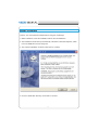
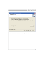
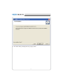
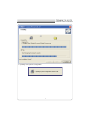
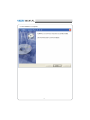
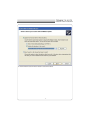
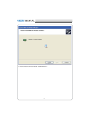
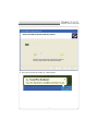
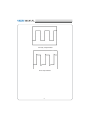
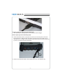
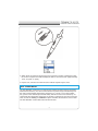
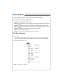
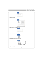
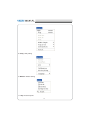
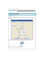
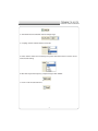
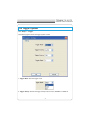
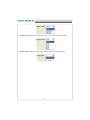
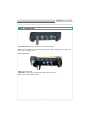
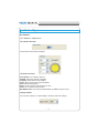
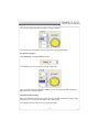
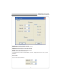
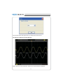
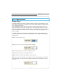
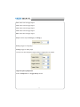
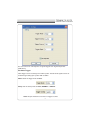
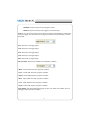
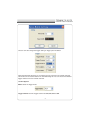
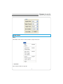
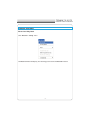
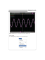
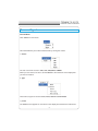
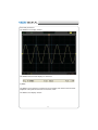
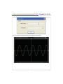
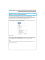
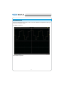
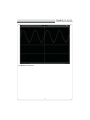
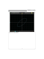
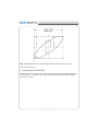
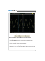
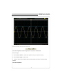
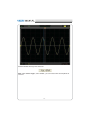
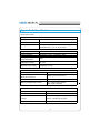
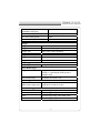
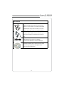
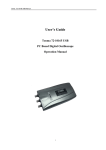
USER’S MANUAL
Tenma 72-10175
www.tenma.com
Tenma Test Equipment 405 S.Pioneer Blvd.Springboro,OH 45066
TENMA 72-10175
DIGITAL OSCILLOSCOPE
USER’S MANUAL
72-10175
X
Content
General Safety Summary ……..………………………….…..3
CHAPTER 1: Getting Started…...…………………………... 4
System Requirement..………………………………....5
Install Software........………………………………...…6
Install Driver............……………………………….....11
General Features....………………………………….16
General Check............…………………………….....17
Probe Compensation.................…………………....17
Functional Check.................………………..……....19
Self Calibration........................................................21
Accessaries.............................................................22
CHAPTER 2: Operating Basics……………………………..23
The User’s Inerface…………………………………...24
The Vertical System…...........………………………..30
The Horizontal System…………………….....……...32
The Trigger System............................……………...33
Input Connectiors..…………………………………...35
CHAPTER 3:Functions..……………… ..…………………...36
Set Ocsilloscope.....................................................37
Set Vertical System.................................................38
Set Horizontal System............................................47
Set Trigger System.................................................55
Save/Load..............................................................55
Utility Function........................................................57
Measure Signal.......................................................65
The Display System................................................73
Zoom In/Out and Drag waveforms..........................78
Interpolation............................................................80
Acquisition..............................................................83
Print........................................................................84
CHAPTER 4: Application Example......………………….....86
Simple Measurement..............................................87
Pass/Fail Test..........................................................89
Capturing a Single Shot Signal...............................93
The Application of The X-Y.......................................94
Taking Cursor Measurements...................................97
CHAPTER 5: Appendix..............……………………...101
Appendix A.............................................................102
Appendix B.............................................................106
Y
TENMA 72-10175
DIGITAL OSCILLOSCOPE
General Safety Summary
Review the following safety precautions carefully before operate the device to avoid any
personal injuries or damages to the device and any products connected to it.
To avoid potential hazards use the device as specied by this user’s guide only.
To Avoid Fire or Personal Injury
Use Proper Power Cord. Use only the power cord specied for this product and
certied for the country of use.
Connect and Disconnect Properly. Do not connect or disconnect probes or test
leads while they are connected to a voltage source.
Connect and Disconnect Properly. Connect the probe output to the measurement
device before connecting the probe to the circuit under test. Disconnect the probe
input and the probe reference lead from the circuit under test before disconnecting
the probe from the measurement device.
Observe All Terminal Rating. To avoid re or shock hazard, observe all ratings
-
and markings on the product. Consult the product manual for further ratings information before making connections to the product.
Use Proper Probe. To avoid shock hazard, use a properly rated probe for your meas-urement.
Avoid Circuit or Wire Exposure. Do not touch exposed connections and compo nents when power is on.
Do Not Operate With Suspected Failures. If suspected damage occurs with the
device, have it inspected by qualied service personnel before further operations.
Provide Proper Ventilation. Refer to the installation instructions for proper ventilation
of the device.
Do not operate in Wet/Damp Conditions.
Do not operate in an Explosive Atmosphere.
Keep Product Surfaces Clean and Dry.
Z
Chapter 1 Getting Start
The 72-10175 is small, lightweight, portable oscilloscope which does not require external
power! The 72-10175 is ideal for production test,research,design and any other applications involving analog circuits test and troubleshooting, as well as education and training.
In addition to the list of general features on the next page, this chapter describes how to
do the following tasks:
System Requirements
Install your product
General Features
General Check
Perform a probe check and compensate probes
Match your probe attenuation factor
Use the self calibration routine
Accessories
[
TENMA 72-10175
DIGITAL OSCILLOSCOPE
System Requirement
To run the oscilloscope software, the needs of computer conguration are as follows:
Minimum System Requirements
Operating System
Window NT/2000/XP/VISTA/Win7
Processor
1.00GHz processor
Memory
256MB
Disk Space
500M disk free space
Screen resolution
800 x 600
Recommended Conguration
Operating System
Windows XP SP3 System
Processor
2.4G Processor
Memory
1GB Memory
Disk Space
80GB Disk Space
Screen resolution
1024 x 768 or 1280 x 1024 resolution
DPI Setting
Normal Size (96DPI)
\
Install Software
Caution: You must install the software before using the oscilloscope.
1. While in Windows, insert the installation CD into the CD-ROM drive.
2. The installation should start up automatically. Otherwise in Windows Explorer, switch
to the CD-ROM drive and run Setup.exe.
3. The software Installation is started. Click 'Next' to continue.
4. Choose a destination directory. Click 'Next' to continue.
]
TENMA 72-10175
DIGITAL OSCILLOSCOPE
5. Check the setup information. Click Next to start copying of les.
^
6. This Status dialog is displayed during copying of les.
_
TENMA 72-10175
DIGITAL OSCILLOSCOPE
7. Updating Your System Conguration.
`
8. The installation is complete.
XW
TENMA 72-10175
DIGITAL OSCILLOSCOPE
Install Driver
1. Connect the A-Type Plug of USB cable to your PC’S USB port.
2. Connect the B-Type Plug of USB cable to USB’S USB port.
3. New hardware is found.
4. New hardware search wizard starts.
XX
5. Select the specic location.
XY
TENMA 72-10175
DIGITAL OSCILLOSCOPE
6. New hardware search wizard starts to search the driver.
XZ
7. New hardware wizard installs “USB DRIVER ”.
X[
TENMA 72-10175
DIGITAL OSCILLOSCOPE
8. The wizard has nished installing for “USB DRIVER”.
X\
General Features
Product features:
Four channel,Bandwidth:
60MHz
Maximum real-time sample rate:
200MSa/s
Memory depth:
10K-16M points
Automatic setup for ease of use (AUTOSET);
Pass/Fail;
Built-in Fast Fourier Transform function(FFT);
20 Automatic measurements;
Automatic cursor tracking measurements;
Waveform storage, record and replay dynamic waveforms;
User selectable fast offset calibration;
Add, Subtract and Multiply Mathematic Functions;
Selectable 20 MHz bandwidth limit;
External trigger;
Waveform average;
Adjustable waveform intensity, more effective waveform view;
User interface in several user-selectable languages;
X]
TENMA 72-10175
DIGITAL OSCILLOSCOPE
General Check
Please check the instrument for the following steps before use.
Check the shipping container for damage:
Keep the damaged shipping container or cushioning material until the contents of the
shipment have been checked for completeness and the instrument has been checked
mechanically and electrically.
Check the accessories:
Accessories supplied with the instrument are listed in "Accessories" in this guide. If the
contents are incomplete or damaged,please notify the distributor.
Check the instrument:
In case there is any mechanical damage or defect, or the instrument does not operate
properly or fails performance tests, please notify the distributor..
Probe Compensation
Perform this function to match the characteristics of the probe and the channel input.
This should be performed whenever attaching a probe to any input channel at the rst
time.
From the “Probe” menu, select attenuation to 1:10. Set the switch to “X10” on the
probe and connect it to CH1 of the oscilloscope. When using the probe hook-tip, insert
the tip onto the probe rmly to ensure a proper connection.
Attach the probe tip to the Probe Compensator and the reference lead to the ground
connector, select CH1, and then press the “AUTOSET“ button into the menu or the
toolbar.
Check the shape of the displayed waveform.
X^
Correctly Compensated
Over compensated
X_
TENMA 72-10175
DIGITAL OSCILLOSCOPE
Under Compensated
If necessary, use a non-metallic tool to adjust the trimmer capacitor of the probe for
the attest square wave being displayed on the oscilloscope.
Repeat if necessary.
WARNNING: To avoid electric shock while using the probe, be sure the perfection of the
insulated cable, and do not touch the metallic portions of the probe head while it is connected with a voltage source.
Function Check
Perform this functional check to verify that your oscilloscope is operating correctly.
Connect the oscilloscope
You should connect the A-Type Plug of USB cable to your PC USB port and connect
the B-Type Plug of USB cable to oscilloscope USB port.
X`
Input a signal to a channel of the oscilloscope
The oscilloscope is equipped with four channels plus external trigger.
Please input signal in the following steps:
1. Set the attenuation switch on the probe as 10X and connect the probe on the oscilloscope with CH1. Allign the slot in the probe connector at the end on BNC of CH1
and insert, then, turn right to lock the probe. Finally, attach the tip of probe and ground
nip to the Connector of Probe compensator.
2. Set the CH1 probe attenuation of the oscilloscope to X10. (The default is X1).
YW
TENMA 72-10175
DIGITAL OSCILLOSCOPE
3. Attach the tip of probe and ground nip to the Connector of Probe compensator. Click
the button. A square wave will be displayed within a several seconds. (Approximately
1 kHz, 2V, peak- to- peak).
4. Inspect CH2 ,CH3 and CH4 with the same method. Repeat steps 2 and 3.
Self Calibration
The self calibration routine lets you optimize the oscilloscope signal path for maximum
measurement accuracy. You can run the routine at any time but you should always run
the routine if the ambient temperature changes by 5v or more. For accurate calibration, power on the oscilloscope and wait twenty minutes to ensure it is warmed up. To
compensate the signal path, disconnect any probes or cables from the input connectors.
Then, access the “Utility -> Calibration” option and follow the directions on the screen.
The self calibration routine takes about several minutes.
YX
Accessories
All the accessories listed below are standard accessories for the oscilloscope:
Probe×2 (1.5m), 1:1, (10:1) Passive Probes
A User’s Guide
An USB Cable
A PC software of the oscilloscope
YY
TENMA 72-10175
DIGITAL OSCILLOSCOPE
Chapter 2 Operating Basics
The User’s Interface
The Menu System
The Vertical System
The Horizontal System
The Trigger System
Input Connectors
YZ
The User’s Interface
Click the software icon on the desk after you nished the software setting and equipment
connecting. Then a user interface will be showed as follows:
In addition to displaying waveforms, the display area is lled with many details about the
waveform and the oscilloscope control settings.
1. The Main Menu
All settings can be found in the main menu.
2. The Toolbar
3. Displays the trigger information
Displays the edge trigger slope, source and level.
4. The Horizontal Panel
Y[
TENMA 72-10175
DIGITAL OSCILLOSCOPE
The user can change Time/Div, format in the panel.
5. The Vertical Panel
The user can turn on/off the CH1/CH2/CH3/CH4. Also the user can change the CH1/
CH2/CH3/CH4 volt/div, coupling and probe attenuation.
6. The Trigger Panel
In this panel, the user can change the trigger mode, sweep, source and slope.
7. Displays the system time.
8. Marker shows Edge trigger level.
9. Displays the main time base setting.
10. Displays the CH4 information
Readouts show the coupling of the channels.
Readouts show the vertical scale factors of the channels.
A “B” icon indicates that the channel is bandwidth limited.
11. Displays the CH3 information
Readouts show the coupling of the channels.
Readouts show the vertical scale factors of the channels.
A “B” icon indicates that the channel is bandwidth limited.
12. Displays the CH2 information
Readouts show the coupling of the channels.
Readouts show the vertical scale factors of the channels.
A “B” icon indicates that the channel is bandwidth limited.
13. Displays the CH1 information
Readouts show the coupling of the channels.
Readouts show the vertical scale factors of the channels.
A “B” icon indicates that the channel is bandwidth limited.
14. Displays the software status.
15. The markers show the reference points of the displayed waveforms. If there is
no marker, the channel is not displayed.
16. The same above.
17. The same above.
18. The same above.
Y\
19. A window that shows the display waveform in buffer position.
20. Marker shows horizontal trigger position.
21. Trigger status indicates the following:
AUTO: The oscilloscope is in auto mode and is acquiring waveforms in the absence
of triggers.
Trig’D: The oscilloscope has seen a trigger and is acquiring the post trigger data.
WAIT: All pretrigger data has been acquired and the oscilloscope is ready to accept
a trigger.
STOP: The oscilloscope has stopped acquiring waveform data.
RUN: The oscilloscope is running.
PLAY: The oscilloscope is displaying the record waveforms.
The Menu System
The Main Menu
1. File: Load or Save data, setup
2. View: Change the user interface
Y]
TENMA 72-10175
DIGITAL OSCILLOSCOPE
3. Setup: Setup setting
4. Display: Change wave display type
5. Cursor: Set Cursor measure type
6. Measure: Set measurement parameters
7.Acquire: Run ,Stop or other operation setting
Y^
8. Utility: Utility setting
9. Window: Window setting
11. Help: Access help le
Y_
TENMA 72-10175
DIGITAL OSCILLOSCOPE
Y`
The Vertical System
Click “Setup”->” Vertical”
The following gure shows the vertical Setup window. It shows the vertical parameters
setting.
1. Select channel : User can select the channel by clicking the Combo box.
2. ON/OFF: Turn on or off the selected channel.
ZW
TENMA 72-10175
DIGITAL OSCILLOSCOPE
3. VOLTS/DIV: Set the selected channel voltage range.
4. Coupling: Set the selected channel to DC/AC.
5. Probe: Set the Select one according to the probe attenuation factor to ensure correct
vertical scale reading
6. BW Limit: Reject the frequency component higher than 20MHz.
7. Invert: Invert the selected wave.
ZX
The Horizontal System
Click ”Setup”->“Horizontal”
The following gure shows the Horizontal System window. It shows the horizontal parameters settings.
1. Time/DIV: leads the setting of the time base parameters
2. Format: leads the setting of the horizontal format parameters
ZY
TENMA 72-10175
DIGITAL OSCILLOSCOPE
The Trigger System
Click “Setup”-> “Trigger”
The following gure shows the trigger system control.
1. Trigger Mode: Sets the trigger mode
2. Trigger Sweep: Selects the trigger sweep mode to AUTO, NORMAL or SINGLE
ZZ
3. Tirgger Source: Selects the trigger source to CH1, CH2, ALT, EXT or EXT/10
4. Trigger Slope: Selects the edge trigger slope to Positive or Negative slope
Z[
TENMA 72-10175
DIGITAL OSCILLOSCOPE
Input Connector
CH1/CH2/CH3/CH4: Input connectors for waveform display.
EXT.: Input connector for an external trigger source. Use the Trigger Menu to select the
Ext. or Ext./10 trigger source.
Other Connector:
GND.: Ground terminal
USB PORT: Connect the B-Type Plug of USB cable to this port.
CAL.: Probe compensation output.
Z\
Chapter 3 Understanding Oscilloscope Functions
Set Oscilloscope
Set Vertical System
Set Horizontal System
Set Trigger System
Save/Load
Utility Function
Measure Signal
Zoom In/Out Waveforms
Acquire Signal
Print
Z]
TENMA 72-10175
DIGITAL OSCILLOSCOPE
Setup the Oscilloscope
Using “AUTOSET” to display a signal automatically
Auto setup functions one time each time you push the “AUTOSET” button. The function
obtains a stable waveform display for you. It automatically adjusts the vertical scale,
horizontal scale and trigger settings. Auto setup also displays several automatic measurements in the graticule area, depending on the signal type.
Connect a signal to the CH1 input:
1. Connect a signal to the oscilloscope as described above.
2. Click the “Acquire -> Autoset” button.
The oscilloscope will change the current settings to display this signal.
Save Setup
The oscilloscope software saves the current setup before you close the oscilloscope
software. The oscilloscope recalls this setup the next time you run the software. You can
use the “Save Setup” menu to permanently save up to several different setups.
Load Setup
The oscilloscope can recall the last setup before the oscilloscope software was running,
any saved setups, or the factory setup. You can use the “Load Setup” menu to permanently recall a setup.
Factory Setup
The oscilloscope software is set up for normal operation when it is shipped from the factory. This is the factory setup. To recall this setup, push the “Factory Setup” menu.
Z^
Set Vertical System
Set Channel
Click “Vertical” in “Setup” Menu.
The Channel Selection
The Channel Control Panel in sidebar
The Vertical function:
Turn ON/Off: Turn on/off the channel
Volt/DIV: Select the channel voltage/div
Coupling: Select the channel coupling
Probe: Select the channel probe attenuation
Filter: Select software lter
Reset: Set the channel vertical position to zero
Invert: Turn on/off the invert function.
BandWidth Limit: Limit the channel bandwidth to 20MHz to reduce noise.
Change Volt/DIV
You can click “Volt/Div” in “Vertical Setup” window to select the voltage
Z_
TENMA 72-10175
DIGITAL OSCILLOSCOPE
You can also change the selected channel voltage in sidebar
You can left click and drag the mouse on the knob to change the voltage.
Set Channel Coupling
Click “Coupling” in “Vertical Setup” window
In the sidebar, you can change the channel coupling too.
You can set the coupling to DC, AC or GND. If you set the coupling to DC, it blocks the
AC component of the input signal.
Probe Attenuation Setting
Select the attenuation factor for the probe. To check the probe attenuation setting, toggle
the probe menu to match the attenuation factor of the probe.
This setting remains in effect before you changed again.
Z`
Click “Probe” in Vertical Setup window to select the probe attenuation
The probe setting window in the sidebar
Note: The attenuation factor changes the vertical scale of the oscilloscope so that the
measurement results reect the actual voltage levels at the probe tip.
Invert
The invert function turns the displayed waveform 180 degrees, with respect to the
ground level. When the oscilloscope is triggered on the inverted signal, the trigger is also
inverted.
Click “Invert” in Vertical window
The following picture shows the waveform before inversion:
[W
TENMA 72-10175
DIGITAL OSCILLOSCOPE
The following picture shows the waveform of inversion:
[X
Set the Channel Bandwidth Limit
The oscilloscope is set to full bandwidth and will pass the high frequency component in
the signal if the “BW Limit” was turned off.
The oscilloscope will reject the frequency component higher than 20MHz if the “BW
Limit” was turned on.
When the “BW Limit” was turned on, a “B” sign will be displayed at the bottom of display
screen.
Set Math
Click “MATH” in Channel menu to set MATH channel.
The MATH Setup window
[Y
TENMA 72-10175
DIGITAL OSCILLOSCOPE
ON/OFF: Turn On/Off the MATH Channel.
Source A/B: Set the sources of the math channel.
Operate: Set operates type of the math channel.
Volt/DIV: Set the resolution of the math channel.
Probe: Set the math channel probe attenuation.
Invert: Turn on/off the invert function
The mathematic functions include addition, subtract, multiply and FFT for CH1, H2,CH3
and CH4.
Source A/B
Source A and Source B Menu
[Z
Operate
Four Types:
A+B
Add source A and source B
A-B
Subtract source B from source A
A×B
Multiply source A by source B
FFT
Convert a time-domain signal into its frequency components (spectrum).
In this function, use the addition, subtraction, multiplication and FFT function to operate
and analyze the waveform.
Select the operation type in the Operate menu. Select source A and B. Then adjust the
vertical scale and offset to view the math channel clearly. The mathematic result can be
measured by the measure and the cursor.
The Math Function Display
Set Reference
[[
TENMA 72-10175
DIGITAL OSCILLOSCOPE
Click “REF” in “Setup” menu to set REF channel.
The Reference Channel Function:
On/Off: Turn on/off the reference channel.
Volt/DIV: Select the resolution of the reference channel.
Load: Load the reference waveform from the “.rfc” le from your computer.
Save: Save the current reference waveform to your computer as “.rfc” format.
Save Reference: Save the current reference waveform to your computer as “.rfc” format.
You can change the vertical scale of a waveform. The waveform display will contract or
expand relative to the reference level.
Load
Click “Load” to load the *.rfc le that was selected. The load le window will appear.
Save
Click “Save ” to save the waveform to *.rfc le. The saved source window appears.
[\
The save le window will appear after you selected the saved source.
The Reference Waveform Display Window:
Note: If you turn on the “Reference” channel, the load le window will appear.
[]
TENMA 72-10175
DIGITAL OSCILLOSCOPE
Setup Horizontal System
Change Time/Div
The “Time/Div”
Selects the horizontal Time/DIV (scale factor) for the main or the window time base
The Horizontal Panel
Click the blue knob can change Time/Div.
If the waveform acquisition is stopped, Time/Div control expands or compresses the
waveform.
Change Format
Click “Time/Div” you can Set the Time base in Horizontal Setup window
In the “Format” item, set the waveform display format (Y-T, X-Y and Roll).
Y – T: Show the relative relation between vertical voltage and horizontal time
Roll: In Roll Mode, the waveform display updates from right to left
X – Y: Show CH1 value at X axis; CH2 value at Y axis
[^
In Roll mode, the waveform display rolls from right to left. No trigger or horizontal offset
control of waveforms is available during Roll Mode, and it’s only available when set to
1s/div or slower.
Note: If the time/div bigger than 1s, the format will change to Roll mode automatically.
Change Horizontal Position
Double click the channel button to set the trigger point to the horizontal center of the
screen.
Horizontal position changes the displayed waveform position, relative to the trigger point.
The user can drag
on screen to change the horizontal position.
[_
TENMA 72-10175
DIGITAL OSCILLOSCOPE
Set Trigger System
Set Edge Trigger
The trigger determines when the oscilloscope starts to acquire data and display a waveform. When a trigger is set up properly, it can convert unstable displays or blank screens
into meaningful waveforms.
If the oscilloscope wants to acquire a waveform, it collects enough data so that it can
draw the waveform to the left of the trigger point. The oscilloscope continues to acquire
data while waiting for the trigger condition to occur. The oscilloscope continues to acquire enough data so that it can draw the waveform to the right of the trigger point after it
detects a trigger.
The Edge trigger determines whether the oscilloscope nds the trigger point on the rising or the falling edge of a signal. Select Edge trigger mode to trigger on Rising edge or
Falling edge.
Mode: Select the trigger mode.
Sweep: Set the sweep mode to Auto, Normal or Single.
Auto: Acquire waveform even when no trigger occurred
Normal: Acquire waveform when trigger occurred.
Single: Acquire waveform when trigger occurred then stop
Source: You can use the trigger source options to select the signal that the oscilloscope
uses as a trigger. The source can be any signal connected to a channel BNC, or to the
EXT. BNC.
[`
CH1: Select CH1 as trigger signal
CH2: Select CH2 as trigger signal
CH3: Select CH3 as trigger signal
CH4: Select CH4 as trigger signal
EXT: Select EXT as trigger signal
Slope: Set the slope to Rising (+) or Falling (-).
Rising: Trigger on rising edge
Falling: Trigger on falling edge
The user can also change the trigger setting on trigger panel in sidebar.
High Frequency Rejection
Select “HF Rejection” in “Trigger Setup” window
\W
TENMA 72-10175
DIGITAL OSCILLOSCOPE
The user can turn on “HF Rejection” to ignore triggers from higher frequencies
(20M above).
Set Pulse Trigger
Pulse trigger occurs according to the width of pulse. The abnormal signals can be detected through setting up the pulse width condition.
Mode: Select the trigger mode to Pulse.
Sweep: Set the sweep mode to AUTO, NORMAL or SINGLE.
AUTO: Acquire waveform even when no trigger occurred
\X
NORMAL: Acquire waveform when trigger occurred.
SINGLE: Acquire waveform when trigger occurred then stop
Source: You can use the trigger source options to select the signal that the oscilloscope
uses as a trigger. The source can be any signal connected to a channel BNC, or to the
EXT. BNC.
CH1: Select CH1 as trigger signal
CH2: Select CH2 as trigger signal
CH3: Select CH3 as trigger signal
CH4: Select CH4 as trigger signal
EXT: Select EXT as trigger signal
PW Condition: Set the PW Condition to the following condition.
+More: +Pulse width more than set pulse condition.
+Less: +Pulse width less than set pulse condition.
+Equal: +Pulse width equal to set pulse condition.
-More: -Pulse width more than set pulse condition.
-Less: -Pulse width less than set pulse condition.
-Equal: -Pulse width equal to set pulse condition.
Pulse Width: The Pulse Width adjust range is 10ns~10s. When the condition is met ,it
will trigger and acquire the waveform.
\Y
TENMA 72-10175
DIGITAL OSCILLOSCOPE
The user can also change the trigger setting on trigger panel in sidebar.
When the alternative trigger is on, the trigger sources come from two vertical channels.
This mode can be used to observe two non-related signals. You can choose two different
trigger modes for the four vertical channels.
Set ALT System
Mode: Select the trigger mode.
Trigger Channel: Set the Trigger Channel to CH1,CH2,CH3 or CH4.
\Z
Trigger Type: Set the Trigger Type to Edge or Pulse.
PW Condition: Set the PW Condition to the following condition.
+More: +Pulse width more than set pulse condition.
+Less: +Pulse width less than set pulse condition.
+Equal: +Pulse width equal to set pulse condition.
-More: -Pulse width more than set pulse condition.
-Less: -Pulse width less than set pulse condition.
-Equal: -Pulse width equal to set pulse condition.
Pulse Width: The Pulse Width adjust range is 10ns~10s. When the condition is met, it
will trigger and acquire the waveform.
The user can also change the trigger setting on trigger panel in sidebar.
\[
TENMA 72-10175
DIGITAL OSCILLOSCOPE
Save/Load
Save
Click “File” in main menu to save waveform, setups and screen
1. Save Data
Save waveform data as a type le
\\
2. Save Setup
Save the current oscilloscope setup to le
3. Save Image
Save the software display window as a .bmp or .jpg le
Load
Click “File” in main menu to recall saved waveform, setup
1. Load Data
Load the waveform that had saved as a type le
2. Load Setup
Load the instrument that had saved
\]
TENMA 72-10175
DIGITAL OSCILLOSCOPE
Utility/Function
Record and Play Back
Click “Record” in “Utility” menu.
The Record window will display. The following picture shows the Record Interface.
\^
This function can record input waveform form CH1,CH2,CH3, or CH4. The maximum
record length is 1000 frames.
Record Setup window
Source:
Select record source channel. (CH1, CH2, CH3 or CH4)
End Frame:
\_
TENMA 72-10175
DIGITAL OSCILLOSCOPE
Set the number of record times. The max frames are 1000.
Record:
Record counter, displays the record frames.
“Start” button:
Start to record frames. After you start to record waveforms, this button changes to
“Stop” button. It stops recording waveforms.
Play back setup window
Start Frame:
Set the start frame of play back.
End Frame:
Set the end frame of play back.
Current Frame:
Displays the current frame of play back. You can also change this number to watch
the waveform one by one.
“Play” button:
Click this button to start playing back waveform. It can stop playing back if you
started playing back.
“Load” button:
Click this button to load a record setup.
Note: When it plays back waveform, the other channel will be turned off.
\`
Pass/Fail
Click “Pass/Fail” in “Utility” menu
The Pass/Fail window appears:
The Pass/Fail function monitors changes of signals and outputs pass or fail signals by
comparing the input signal with the pre-created mask.
Control Setting
]W
TENMA 72-10175
DIGITAL OSCILLOSCOPE
Source:
Select the Pass/Fail channel
Output:
Select the Pass/Fail output condition
Stop When Output:
If it was checked, the Pass/Fail will stop when output.
Mask Setting
Vertical:
Set the vertical limit range
Horizontal:
Set the horizontal limit range
“Create” button:
]X
Click this button to create Pass/Fail area according to the mask
“Save” button:
Click this button to save the setups to le.
“Load” button:
Click this button to load the saved setups le.
Information Display
Fail:
Displays the fail waveform number
Pass:
Displays the pass waveform number
Total:
Displays the l total Pass/Fail waveform number
Operation
Click “Start” button to start the Pass/Fail test.
Click “Stop” button to stop the Pass/Fail test.
The Pass/Fail function display
]Y
TENMA 72-10175
DIGITAL OSCILLOSCOPE
NOTE: Pass/Fall function is unavailable In X-Y mode and Roll mode.
Factory Setup
Click “Factory Setup” in “Utility” menu to load default setups
]Z
When you click the Factory Setup in Utility menu, the oscilloscope displays the CH1
and CH2 waveforms and removes all other waveforms.
The oscilloscope set up for normal operation when it is shipped from the factory and can
be recalled at anytime by user.
The Factory Setup function does not reset the following settings:
Language option
Date and time
Language
Click “Language” in “Utility” menu
There are four languages in “Language” menu. The default language is English.
][
TENMA 72-10175
DIGITAL OSCILLOSCOPE
Measure Signal
Cursor Menu
Click “Cursor” in main menu
This method allows you to take measurements by moving the cursors
1. Source
The user can set the source to CH1, CH2, CH3,CH4 and MATH.
When you use cursors, be sure to set the Source to the waveform on the display that
you want to measure.
2. Type
There are four types of cursors: Cross, Trace, Vertical and Horizontal
1) Cross
The Cross cursors appear as cross lines on the display and measure the vertical and
]\
horizontal parameters.
The Cross cursor display window
The Cross measure result displays on status bar
2) Trace
The Trace cursors appear as vertical lines on the display and measure the waveform
amplitude at the point the waveform crosses the cursor.
The Trace cursor display window
]]
TENMA 72-10175
DIGITAL OSCILLOSCOPE
The Trace cursor measure result displays on status bar
3) Vertical
The Vertical cursors appear as vertical lines on the display and measure the vertical
parameters.
The Vertical cursor display window
]^
The Vertical cursor measure result displays on status bar
4) Horizontal
The Horizontal cursors appear as horizontal lines on the display and measure the horizontal parameters.
The Horizontal cursor display window
]_
TENMA 72-10175
DIGITAL OSCILLOSCOPE
The Horizontal cursor measure result displays on status bar
Measure Menu
Click “Measure” in main menu
The oscilloscope provides 20 parametric auto measurements (12 voltage and 8 time
measurements).
]`
1. Source
The user can use the “Source” menu to select a measure source.
2. Vertical
Maximum: Voltage of the absolute maximum level, Measured over the entire waveform
Minimum: Voltage of the absolute minimum level, Measured over the entire waveform
Peak To Peak: Peak-to-peak = Max – Min, Measured over the entire waveform
Top: Voltage of the statistical maximum level, Measured over the entire waveform
Base: Voltage of the statistical minimum level, Measured over the entire waveform
Middle: Voltage of the 50% level from base to top
^W
TENMA 72-10175
DIGITAL OSCILLOSCOPE
RMS: The Root Mean Square voltage over the entire waveform
Amplitude: Amp = Base – Top, Measured over the entire waveform
Mean: The arithmetic mean over the entire waveform
Cycle Mean: The arithmetic mean over the rst cycle in the waveform
Preshoot: Positive Overshoot = (Max - Top)/Amp x 100 %, Measured over the entire
waveform
Overshoot: Negative Overshoot = (Base - Min)/Amp x 100 %, Measured over the entire
waveform
3. Horizontal
Period: Time to take for the rst signal cycle to complete in the waveform
Frequency: Reciprocal of the period of the rst cycle in the waveform
Rise Time: Time taken from lower threshold to upper threshold
Fall Time: Time taken from upper threshold to lower threshold
+Duty Cycle: Positive Duty Cycle = (Positive Pulse Width)/Period x 100%, Measured of
the rst cycle in waveform
-Duty Cycle: Negative Duty Cycle = (Negative Pulse Width)/Period x 100%, Measured
of the rst cycle in waveform
^X
+Pulse Width: Measured of the rst positive pulse in the waveform. The time between
the 50% amplitude points
-Pulse Width: Measured of the rst negative pulse in the waveform. The time between
the 50% amplitude points
4. Clear Measure
Clear all measure items on display screen.
The Measure Display Window
Note: The results of the automatic measurements will be displayed on the bottom of
the screen. Maximum 8 results can be displayed at the same time. When there is no
room, the next new measurement result will make the previous results move left, out of
screen.
^Y
TENMA72-10175
DIGITAL OSCILLOSCOPE
The Display System
Display Type
Click “Type” in “Display” menu.
The following gure shows the type parameters setting.
If the Vectors type mode is selected, the waveform will be displayed as following gure.
If the Dots type mode is selected, the waveform will be displayed as following gure.
^Z
Display Grid
Click “Display” in main menu
The grid shows:
^[
TENMA 72-10175
DIGITAL OSCILLOSCOPE
without the grid displayed:
^\
Intensity and Persistence
Click “Display->Intensity” in main menu
The following gure shows the intensity dialog. It shows the display parameters setting.
^]
TENMA 72-10175
DIGITAL OSCILLOSCOPE
You can change the grid and waveform color intensity in this dialog.
^^
Zoom In/Out and Drag Waveforms
The software will stop updating waveform after the user clicks “ Stop ” button,
The user can change the waveform display by adjusting the scale and position. When
you change the scale, the waveform display will increase or decrease in size. When you
change the position, the waveform will move up, down, right, or left.
The channel reference indicator identies each waveform on the display. The indicator
points to the reference level of the waveform record.
Zoom In/Out
The user can click “Zoom In/Out” in “Acquire” menu, then left or right click the mouse
button on display screen to zoom in/out the waveform. Also the user can change Time/
Div in Horizontal menu or in Horizontal panel to zoom in/out the waveform.
Drag
The user can modify the waveform position after clicked “Drag” in “Acquire” menu following the following steps.
^_
TENMA 72-10175
DIGITAL OSCILLOSCOPE
1. Select Channel:
2. Set the Move Step:
3. Change the waveform position:
^`
Interpolation
At the time base 40ns/div or faster, user can use the 3 different interpolation mode to get
waveforms of different clarity.
The Step Interpolation
The Linear Interpolation
_W
TENMA 72-10175
DIGITAL OSCILLOSCOPE
The Sin(x)/x Interpolation
_X
Note: The default interpolation mode is Sin(x)/x.
Acquisition
When you acquire a signal, the oscilloscope converts it into a digital form and displays
a waveform. The acquisition mode denes how the signal is digitized and the time base
setting affects the time span and level of detail in the acquisition.
_Y
TENMA 72-10175
DIGITAL OSCILLOSCOPE
Acquisition Modes
There are two acquisition modes: Normal and Average.
Normal: In this acquisition mode, the oscilloscope samples the signal in evenly spaced
intervals to construct the waveform.
Average: In this acquisition mode, the oscilloscope acquires several waveforms, averages them, and displays the resulting waveform. You can use this mode to reduce
random noise.
ETSIn this acquisition mode, you can test high frequency cycle signal.
_Z
Print And Print Preview
1. Click “Print” in “File” menu to set the printer to print the current waveform.
The Print report
_[
TENMA 72-=
10175
DIGITAL OSCILLOSCOPE
2. Click the “PrintPreview” in “File” menu to get into the Preview window.
In”PrintPreview” window, use the “Zoom In” button and the “Zoom Out” button to
change the size of the waveform graph. Click the “Close” button to turn this window off
and click the “Print” button to print the report.
_\
Chapter 4 Application Examples
Sample Measurement
Pass/Fail Test
Capturing a Single-Shot Signal
The Application of the X-Y
Taking Cursor Measurement
_]
TENMA 72-10175
DIGITAL OSCILLOSCOPE
Simple Measurement
To acquire and display a signal, follow these steps:
1. Connect signal to CH1 by using probe
2. Click the "AUTO" button on toolbar or “ Acquire -> Auto Setup” on menu.
The Tenma set the vertical, horizontal, and triggers controls at the best status automatical
ly. Also, you can adjust the controls to meet your measurement to optimize the waveform
display.
To measure the frequency and “Vpp”, follow these steps:
1. Click the “Measure->Horizontal->Frequency” button, the frequency of the signal
display on the bottom of the waveform interface.
2. Click the “Measure->Vertical->Peak-to-Peak” button, the “Vpp” of the signal will also
display on the bottom of the waveform interface.
3. To clear the measurement on the waveform interface, click the “Measure->Clear
Measure” button.
_^
__
TENMA 72-10175
DIGITAL OSCILLOSCOPE
Pass/Fail Test
The Pass/Fail function monitors changes of signals and outputs pass or fail signals by
comparing the input signal with the pre-created mask.
Control Setting
Source:
Select the Pass/Fail channel
Output:
_`
Select the Pass/Fail output condition
Stop When Output:
If it was checked, the Pass/Fail will stop when output.
Mask Setting
Vertical:
Set the vertical limit range
Horizontal:
Set the horizontal limit range
“Create” button:
Click this button to create Pass/Fail area according to the mask
“Save” button:
Click this button to save the setups to le.
“Load” button:
Click this button to load the saved setups le.
Information Display
`W
TENMA 72-10175
DIGITAL OSCILLOSCOPE
Fail:
Displays the fail waveform number
Pass:
Displays the pass waveform number
Total:
Displays the total Pass/Fail waveform number
Operation
Click “Start” button to start the Pass/Fail test.
Click “Stop” button to stop the Pass/Fail test.
The Pass/Fail function display
`X
NOTE: Pass/Fall function is unavailable In X-Y mode and Roll mode.
`Y
TENMA 72-10175
DIGITAL OSCILLOSCOPE
Capturing a Single-Shot Signal
To capture a single event, it needs to gather some pre-test knowledge of the signal in
order to set up the trigger level and slope correctly. For example, if the event is derived
from 3.3V COMS logic, a trigger level of 1.2 or higher Volts should work on a rising edge.
Do these steps as follows:
1. Set the probe and the channel attenuations to X 10.
2. Set up the trigger in the Trigger Menu, or in the Trigger Setting window.
1) Adjust the Trigger Mode to Edge.
2) Set the Trigger Sweep to Single.
3) Set the Trigger Source to CH1.
4) Set the Trigger Slope to “+” which means you select the rising edge.
5) Adjust the Volts/Div and the time base in a proper range for the signal.
6) Drag the trigger level sign on the waveform display screen to proper position. It’s usually higher a little above the normal level.
7) Click START button to start capturing. When the trigger conditions are met, data appears on the display representing the data points that the oscilloscope obtained with one
acquisition.
This function helps to capture the signal occurrence easily, such as the noise with large
amplitude; set the trigger level higher a little above the normal level and press and wait.
When noise occurs, the instrument will record the waveform before and after the trigger.
`Z
The Application of the X-Y Operation
X-Y Plot acts to analyze correlation of data of two channels. Lissajous diagram is
displayed in the screen when you use X-Y Plot, which enables to compare frequencies,
amplitudes and phases of counterpart waveform against the reference waveform. This
makes it possible to compare and analyze frequency, amplitude and phase between
input and output.
Do these steps as follows:
1. Set the probe attenuation to “x10”. Set the switch to “x10” on the probes.
2. Connect the CH1 probe to the input of the circuit, and connect the CH2 probe to the
output of the circuit.
3. Click "auto" button.
4. Adjust the vertical scale and offset to display approximately the same amplitude signals on each channel.
5. Select X-Y format at Horizontal window. The oscilloscope will displays a Lissajous pattern representing the input and the output characteristics of the circuit.
6. Adjust the scale and offset of the horizontal and vertical to a desirable waveform display. The following picture shows a typical example.
7. Apply the Ellipse Method to observe the phase difference between the two channels.
Signal in X-Y Format:
`[
TENMA 72-10175
DIGITAL OSCILLOSCOPE
Instruction of the Ellipse Method
`\
Sin = A/B or C/D, where = phase shift (in degrees) between the two signals.
From the formula above:
= ±arcsine (A/B) or ±arcsine (C/D)
must be in the range of (0~/2) or (3/2~2) if the main axis of the ellipse is between
I and III quadrant, . If the main axis is at II and IV quadrant, must be in the range of
(/2~) or (~3/2).
`]
TENMA 72-10175
DIGITAL OSCILLOSCOPE
Taking Cursor Measurements
Use cursors to make time and amplitude measurements on a waveform quickly.
Measure the Peak Frequency or Time of the First Sine Waveform
Do these steps:
1. Click “Cursor->Source”, select CH1 (select CH2 if you want measure CH2).
2. Click “Cursor->Type”, select Vertical.
3. Push left mouse button, and the vertical lines appear.
4. Drag the mouse button to the point you want to measure.
5. Release the left mouse button, the frequency difference and time difference will be
shown at the status bar.
Measure the Frequency and Time:
`^
Read the details showing in the status bar.
Measure the Amplitude of the First Waveform Peak of the Waveform
Do these steps:
1. Click “Cursor->Source”, select CH1 (select CH2 if you want measure CH2).
2. Click “Cursor->Type”, select Horizontal.
3. Push left mouse button, and the Horizontal lines appear.
4. Drag the mouse button to the point you want to measure.
5. Release the left mouse button, the voltage difference will be shown at the status bar.
Measure the Amplitude:
`_
TENMA 72-10175
DIGITAL OSCILLOSCOPE
Read the details showing in the status bar.
Trace the Amplitude of a xed position on X-axis in a Waveform
Do these steps:
1. Click “Cursor->Source”, select CH1 (select CH2 if you want trace CH2).
2. Click “Cursor->Type”, select Trace.
3. Click the cursor at the position that you want traced of the wave in the waveform
window.
Trace the Amplitude:
``
Read the details showing in the status bar.
Note: Click “Cursor->Type”, select “Cross”, you can measure time and amplitude at
one time.
XWW
TENMA 72-10175
DIGITAL OSCILLOSCOPE
Chapter 5 Appendix
Appendix A: Specications
Appendix B: General Maintenance
XWX
Appendix A: Specications
Specications Table:
Acquisition
Sample Mode
Real-Time Sample
Sample Rate
200MSa/s
Average
N acquisitions, all channels simultaneously, N is
selectable from 2, 4, 8, 16, 64, and 128
Input Input
Input Couplin
Input Impedance
PP-80, PP-150, PP-200
Probe Attenuation
DC, AC, GND
Resistance: 1Mȍ ; Capacitance: 25pF
Supported Voltage Probe
Attenuation Factors
1X, 10X
Maximum Input Voltag
400Vpk(DC+ peak)
10X
Horizontal
Scanning Speed Range(Sec/Div)
Sample Rate and
Delay Time Accuracy
Wave form Interpolation
Memory Depth(Sample Points)
5ns/div ~ 1000s/div(1-2-5 sequences)
±50ppm( any interval 1ms )
Step, Linear, Sin(x)/x
10K ~ 16M for each channel
16M: 5ns/div-1000s/div
Vertical
Analog Bandwidth
60MHz (-3dB)
A/D converter
8-bit resolution
Vertical Scale(Volt/div)
10mV ~ 5V/div @ x1 probe(1,2,5 sequence)
100mV ~ 50V/div @ x10 probe
Range
Position Range
±4 division
102
TENMA 72-10175
DIGITAL OSCILLOSCOPE
Selectable Analog
20MHz
Bandwidth Limit(typical)
Lower Frequency Response(-3dB)
10Hz(at input BNC)
Rise Time at BNC(typical)
5.8ns
DC Gain Accuracy
±3%
Trigger
Trigger Source
CH1,CH2,CH3, CH4,EXT
Trigger Mode
Auto, Normal and Single
Trigger Type
Edge, Pulse, Video, Alternative
Trigger Sensitivity
0.02 div increments
Trigger Level Range
±4V
Trigger Level Accuracy
±4 division
Edge Trigger
Edge Trigger Slope
Rising, Falling
Pulse Width Trigger
Trigger Condition
Trigger when < (Less than), > (Greater than), =
(Equal), or (Not Equal); Positive pulse or
Negative pulse
Pulse Width Range
Selectable from 20ns to 10s
Video Trigger
Signal Formats and Field
Supports NTSC, PAL and SECAM broadcast
Rates, Video Trigger Type
systems for any field or any line
Alternative Trigger
CH1
Internal Trigger: Edge, Pulse Width, Video
CH2
Internal Trigger: Edge, Pulse Width, Video
CH3
Internal Trigger: Edge, Pulse Width, Video
CH4
Internal Trigger: Edge, Pulse Width, Video
XWZ
Measurement
Cursor
Amplitude difference between cursors (V)
Time difference between cursors (t)
Reciprocal of t in Hertz (1/ t)
(Cross, Trace, Horizontal, Vertical)
Voltage
Vp-p, Vmax, Vmin, Vmean, Vamp, Vtop,
Measurement
Vbase, Vmid, Vrms, Vcrms,Preshoot,
Overshoot
Auto Measure
Time
Frequency, Period, Rise Time(10%~90%),
Measurement
Fall Time(10%~90%), Positive Width,
Negative Width, Duty Cycle
Frequency Counter
Readout Resolution
6 digits
Environmental
Temperature
Operating: 0ć to 40ć
Non-operating: -20ć to +60ć)
Cooling Method
Forced air
Humidity
Below +35ć, 90% relative humidity
+35ć to +40ć, 60% relative humidity
Altitude
Operating
3,000m or below
Non-operating
15000m or below
Mechanical
Size
Heavy
Width
255mm
Height
190mm
Depth
45mm
Without package
1kg
XW[
Tenma 72 SERIES
DIGITAL OSCILLOSCOPE
Accessories
X1, X10 four passive probes. The passive probes have
a 6MHz bandwidth (rated 100Vrms CAT III) when the
switch is in the X1 position, and a maximum bandwidth
(rated 300Vrms CAT II) when the switch is in the X10
position. Each probe consists of all necessary fittings.
A power adapter special for this product. In addition to
the power adapter shipped with your instrument, you
may purchase another one certified for the country of
use.
A USB A-B line, used to connect external devices with
USB-B interface like a printer or to establish
communications between PC and the oscilloscope.
A software installation CD. It contains the user manual
of Tenma 72, giving particular descriptions on the
Tenma 72 series oscilloscopes.
XW\
Tenma 72 SERIES
DIGITAL OSCILLOSCOPE
Appendix B: General Maintenance
General Care
Do not store or leave the oscilloscope where the device will be exposed to direct sunlight
for long periods of time.
Caution
To avoid damages to the device or probes, do not expose them to sprays, liquids or
solvents.
Cleaning
Inspect the device and probes as often as operating conditions require. Make sure to
disconnect from all power sources.
To clean the exterior surface, perform the following steps:
1. Remove loose dust on the outside of the oscilloscope and probes with a lint-free cloth.
Use care to avoid scratching.
2. Use a soft cloth to clean the device.
Caution
To avoid damages to the surface of the device or probes not use any abrasive or chemical cleaning agents.
XW]