1
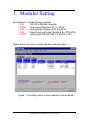
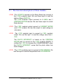
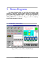
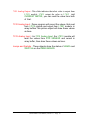
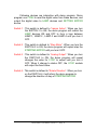
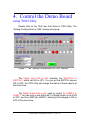
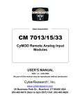
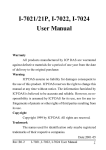
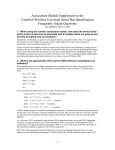
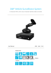
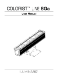
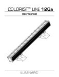
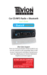
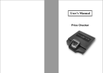
Demo Board I
User Manual
Warranty
All products manufactured by ICPDAS Inc. are warranted against defective
materials for a period of one year from the date of delivery to the original purchaser.
Warning
ICPDAS Inc. assume no liability for damages consequent to the use of this product.
ICPDAS Inc. reserves the right to change this manual at any time without notice. The
information furnished by ICPDAS Inc. is believed to be accurate and reliable. However,
no responsibility is assumed by ICPDAS Inc. for its use, nor for any infringements of
patents or other rights of third parties resulting from its use.
Copyright
Copyright 1997-1999 by ICPDAS Inc. All rights are reserved.
Trademark
The names used for identification only maybe registered trademarks of their
respective companies.
License
The user can use, modify and backup this software
on a single
machine. The user may not reproduce, transfer or distribute this software, or any
copy, in whole or in part.
Demo Board I User Manual (version 1.1) – Page 1
Table of Contents :
1. Modules Setting ......................................................................................... 3
2. System Architecture................................................................................... 4
2.1 The function description of these module :......................................... 5
3. Demo Programs.......................................................................................... 6
3.1 Demo Kit (Test Point)......................................................................... 6
3.2 Demo Kit (Visual Basic)..................................................................... 7
3.3 Demo Kit (Delphi) .............................................................................. 8
3.4 Demo Kit (BCB) ................................................................................. 8
3.5 Function Descriptions for Demo program .......................................... 9
4. Control the Demo Board using 7000 Utility............................................ 12
5. PROBLEMS REPORT........................................................................... 14
Demo Board I User Manual (version 1.1) – Page 2
1. Modules Setting
Demo Board I , Include following modules …
I-7520
: RS-232 to RS-485 Converter
I-7012D
: Analog Input Module at #1, +/- 20mA
I-7021
: Analog Output Module at #2, 0 to 20mA
I-7044
: Digital Input and Output Module at #3, 4*DI+8*DO
I-7013D
: Analog Input Module at #4, PT/.00385 +/-100
Please ensure that every module has been setted as figure 1 .
Figure 1. The setting value of every module for Demo Board I
Demo Board I User Manual (version 1.1) – Page 3
2. System Architecture
Figure 2. System Architecture
Demo Board I User Manual (version 1.1) – Page 4
2.1 The function description of these module :
I-7044 : The 4 SWITCH devices on the Demo Board are connect to
the I-7044 module’s input. We use these input to read the
status of these SWITCHs.
The I-7044 module’s output connnect to 4 LAMPs and 1
STEPPING MOTOR devices. We use these output to control
these devices.
I-7021 : The I-7021 module’s output connect to CURRENT METER
and I-7012 module. We use this output to send voltage as
sine-wave.
I-7012 : The I-7012 module’s input is connect to I-7021 module’s
output. We use this input to read the voltage value from I7021.
The PHOTO INTERRUPT is beside on the STEPPING
MOTOR,and it is connect to the I-7012 module’s DIO/EV. It
notifies the I-7012 to increase the COUNTER/EVENT when
the PHOTO INTERRUPT sense that the photo status has
been changed.
I-7013 : The I-7013 module’s input is connect to RTD SENSOR. We
use this input to read the temperature from RTD SENSOR.
Demo Board I User Manual (version 1.1) – Page 5
3. Demo Programs
The Demo Program written in Test Point can be setup under
Windows 3.1/95/98/NT, and the Demo Program of VB/BCB/Delphi
can be runed under Windows 95/98/NT. The most of the functions of
Demo Program of Test Point are the same as the Demo Program of
VB/Delphi/BCB. The overall Demo Programs with its completely
source codes are place in the disk.
3.1 Demo Kit (Test Point)
Figure 3. The window of Demo Kit (Test Point)
Demo Board I User Manual (version 1.1) – Page 6
3.2 Demo Kit (Visual Basic)
The demo program is written in Visual Basic 5.0, for work
correctly, you need to install the Visual Basic 5.0 on your system.
Figure 4. The window of Demo Kit (VB)
Demo Board I User Manual (version 1.1) – Page 7
3.3 Demo Kit (Delphi)
Figure 5. The window of Demo Kit (Delphi)
3.4 Demo Kit (BCB)
Figure 6. The window of Demo Kit (BCB)
Demo Board I User Manual (version 1.1) – Page 8
3.5 Function Descriptions for Demo program
The following functions can be controled in the demo program.
COM Port : Before active the demo program, you must select the
correct COM port that you are using.
Active/Stop Button : Use it to ACTIVE or STOP the demo program.
Exit Button : Use it to end the demo program.
Motor Steps Edit Box : This edit box let you specify the steps of
STEPPING MOTOR. It will stop when it steps reach
the value. After stop, you can change the value of
Motor Steps Edit Box, or turn off the SWITCH Step
Motor and then turn on, to restart the STEPPING
MOTOR.
It will repeat stepping when this value is 0, and it will
not work when the SWITCH Step Motor is off.
Interval of Steps Edit Box : This edit box let you adjust the speed of
STEPPING MOTOR, that is, increase the value to
slow down the speed or decrease the value to speed it.
Interval of 7013D Analog Input Edit Box : This edit box let you
adjust the sampling rate of 7013D analog input. Thus,
increase the value to reduce the sampling rate or
decrease the value to improve the sampling rate.
The following functions indicate the DEMO BOARD’s status.
Module Status : These objects show the status of modules. If one
module can not be accessed then the relative object’s
backcolor changed to RED, else backcolor setted to
BLUE.
Demo Board I User Manual (version 1.1) – Page 9
7021 Analog Output : This slider indicates that what value is output from
I-7021 module. I-7021 output the value to I-7012 and
CURRENT METER, you can read the value from both
of that.
7012 Analog Input : Demo program will record the values, that read
from I-7012 module and output from I-7021 module, in
array buffers.This picture object will draw these values
as lines.
7013 Analog Input : As 7012 Analog Input, the I-7013 module will
read the values from RTD SENSOR and record in
array buffer, then draw these values as lines .
Lamps and Switchs : These objects show the status of LAMPs and
SWITCHs on the DEMO BOARD.
Demo Board I User Manual (version 1.1) – Page 10
Following devices are interactive with demo program. Demo
program use I-7044 to read the digital value from these devices, and
output the digital value to LAMP devices and SETTING MOTOR
device.
Switch-1 : This switch is defined to “Lamps Action”. When you turn
the SWITCH-1 to ON, the demo program will control the
LAMP devices ON and OFF to form a loop between
LAMP-1, LAMP-2 , LAMP-3 and LAMP-4 until you turn it
OFF.
Switch-2 : This switch is defined to “Step Motor”. When you turn the
SWITCH-2 to ON, the demo program will repeat step the
STEPPING MOTOR until you turn it OFF.
Switch-3 : This switch is defined to “Analog Output”. When you turn
the SWITCH-3 to ON, the demo program will repeat
changes the value for I-7021 to output until you turn it
OFF. When it change to status OFF, the I-7021 module
will output the fixed value.
Switch-4 : This switch is defined to “Rotate Direction”. When you turn
on the SWITCH-4, it will inform the demo program to
change the direction of step of STEPPING MOTOR.
Demo Board I User Manual (version 1.1) – Page 11
4. Control the Demo Board
using 7000 Utility
Double click on the 7044 item that listed in 7000 Utility. The
“Setting Configuration for 7044” window will pupop.
Figure 7. The “Setting Configuration for 7044” window
The Digital Input bit0 to bit3 indicates the SWITCH-4 to
SWITCH-1 which are ON or OFF. You can put the SWITCH devices
ON or OFF, the 7000 utility will change the status of these objects at
the same time.
The Digital Output bit4 to bit7 used to control the LAMP-4 to
LAMP-1. You can click on the bit4(to bit7) of Digital Output to let it ON
or OFF, and the LAMP-4(to LAMP-1) device(s) will changed to ON or
OFF at the same time.
Demo Board I User Manual (version 1.1) – Page 12
The Digital Output bit0 to bit3 used to control the STEPPING
MOTOR. Use following steps to step the STEPPING MOTOR :
1.
2.
3.
4.
5.
6.
7.
8.
Click on the bit0 object of Digital Output to let it ON.
Click on the bit0 object of Digital Output to let it OFF.
Click on the bit1 object of Digital Output to let it ON.
Click on the bit1 object of Digital Output to let it OFF.
Click on the bit2 object of Digital Output to let it ON.
Click on the bit2 object of Digital Output to let it OFF.
Click on the bit3 object of Digital Output to let it ON.
Click on the bit3 object of Digital Output to let it OFF.
These steps let the STEPPING MOTOR to step 4 times. If you
want to step the STEPPING MOTOR in another direction, the steps
as followings :
1.
2.
3.
4.
5.
6.
7.
8.
Click on the bit3 object of Digital Output to let it ON.
Click on the bit3 object of Digital Output to let it OFF.
Click on the bit2 object of Digital Output to let it ON.
Click on the bit2 object of Digital Output to let it OFF.
Click on the bit1 object of Digital Output to let it ON.
Click on the bit1 object of Digital Output to let it OFF.
Click on the bit0 object of Digital Output to let it ON.
Click on the bit0 object of Digital Output to let it OFF.
Demo Board I User Manual (version 1.1) – Page 13
5. PROBLEMS REPORT
Technical support is available at no charge as described below. The best
way to report problems is send electronic mail to
[email protected]
on the Internet.
When reporting problems, please include the following information:
1. Is the problem reproducible? If so, how?
2. What the Operation Systems that you using? For example, Windows 3.1,
Windows for Workgroups, Windows NT 4.0, etc.
3. What kinds of our products that you using? Please see the product's manual .
4. If a dialog box with an error message was displayed, please include the full
text of the dialog box, including the text in the title bar.
5. If the problem involves other programs or hardware devices, what devices or
version of the failing programs that you using?
6. Other comments relative to this problem or any Suggestions will be
welcomed.
After we received your comments, we will take about two business days to
testing the problems that you said. And then reply as soon as posible to you.
Please check that we have received your comments? And please keeping
contact with us.
E-mail: [email protected]
Demo Board I User Manual (version 1.1) – Page 14