1
USBwiz™ User Manual
Revision 2.07
GHI Electronics, LLC
*Preliminary and Incomplete document*
Updated – May 24, 2006
USBwiz™
USB Devices Made Accessible
Table of Contents
1.
USB BUS........................................................................................................................................... 4
1.1.
INTRODUCTION ......................................................................................................................................... 4
1.2.
USB, ONE HOST AND MULTIPLE DEVICES! ................................................................................................ 4
1.3.
IN SHORT, WHAT IS USB? ......................................................................................................................... 4
1.3.1.
USB 101! ....................................................................................................................................... 4
1.3.2.
Transfer Speeds ............................................................................................................................ 5
1.3.3.
Transfer Types .............................................................................................................................. 5
2.
FROM USBWIZ V1 TO USBWIZ V2 ................................................................................................. 7
3.
WHAT IS USBWIZ? .......................................................................................................................... 8
3.1.
3.2.
3.3.
3.4.
INTRODUCTION ......................................................................................................................................... 8
SUPPORTED USB CLIENT CLASSES .......................................................................................................... 8
KEY FEATURES ........................................................................................................................................ 8
SOME EXAMPLE APPLICATIONS ................................................................................................................. 9
4.
PIN-OUT AND DESCRIPTION........................................................................................................ 10
5.
USBWIZ BOOT LOADER ............................................................................................................... 12
5.1.
5.2.
5.3.
5.4.
6.
COMMANDING WITH USBWIZ...................................................................................................... 14
6.1.
6.2.
6.3.
6.4.
7.
GENERAL DESCRIPTION.......................................................................................................................... 12
USING THE BOOT LOADER ...................................................................................................................... 12
BOOT LOADER COMMANDS ..................................................................................................................... 12
BOOT LOADER ERROR CODES ................................................................................................................ 13
SELECTING AN INTERFACE ...................................................................................................................... 14
UART INTERFACE .................................................................................................................................. 14
SPI INTERFACE MODE ............................................................................................................................ 15
I2C INTERFACE MODE ............................................................................................................................ 16
USBWIZ FUNCTIONS..................................................................................................................... 17
7.1.
FAT STORAGE MEDIA ............................................................................................................................ 17
7.1.1.
Directories (folders) ..................................................................................................................... 18
7.1.2.
Files ............................................................................................................................................. 18
7.2.
USB MASS STORAGE ............................................................................................................................. 18
7.3.
USB HUMAN INTERFACE DEVICE ............................................................................................................ 19
7.4.
USB PRINTERS ...................................................................................................................................... 20
7.5.
USB COMMUNICATION DEVICE ............................................................................................................... 20
7.6.
FTDI DEVICE ......................................................................................................................................... 21
7.7.
USB RALINK W I-FI 802.11..................................................................................................................... 22
7.8.
RAW USB ACCESS ................................................................................................................................ 22
8.
USBWIZ COMMANDS SET ............................................................................................................ 25
8.1.
8.2.
8.3.
8.4.
8.5.
8.6.
8.7.
8.8.
8.9.
8.10.
8.11.
VR GET VERSION NUMBER..................................................................................................................... 25
BR SET UART BAUD RATE .................................................................................................................... 25
AM ATTACH STORAGE DEVICE “STORAGE MEDIA”................................................................................... 26
RS READ SECTOR ................................................................................................................................. 26
WS W RITE SECTOR ............................................................................................................................... 26
MU MOUNT FILE SYSTEM MEDIA ............................................................................................................ 27
SS SWITCH BETWEEN FILE SYSTEM MEDIAS ........................................................................................... 27
MS GET MEDIA STATISTICS .................................................................................................................... 28
QF QUICK FORMAT MEDIA...................................................................................................................... 28
IL INITIALIZE LIST FILES AND FOLDERS .................................................................................................... 28
NF GET NEXT DIRECTORY ENTRY........................................................................................................... 28
GHI Electronics, LLC.
2 of 51
User Manual
USBwiz™
8.12.
8.13.
8.14.
8.15.
8.16.
8.17.
8.18.
8.19.
8.20.
8.21.
8.22.
8.23.
8.24.
8.25.
8.26.
8.27.
8.28.
8.29.
8.30.
8.31.
8.32.
8.33.
8.34.
8.35.
8.36.
8.37.
8.38.
8.39.
8.40.
8.41.
8.42.
8.43.
8.44.
8.45.
8.46.
8.47.
8.48.
8.49.
8.50.
8.51.
8.52.
8.53.
8.54.
8.55.
8.56.
8.57.
8.58.
USB Devices Made Accessible
MD MAKE DIRECTORY............................................................................................................................ 28
CD CHANGE DIRECTORY ........................................................................................................................ 29
RD REMOVE DIRECTORY ........................................................................................................................ 29
OF OPEN A FILE FOR READ, WRITE OR APPEND ........................................................................................ 29
CF CLOSE FILE HANDLE ......................................................................................................................... 30
FF FLUSH FILE DATA.............................................................................................................................. 30
RF READ FROM FILE .............................................................................................................................. 30
WF W RITE TO FILE................................................................................................................................. 31
SW SHADOW W RITE TO MULTIPLE FILES ................................................................................................. 31
RW READ FROM FILE, W RITE TO OTHER FILE........................................................................................... 32
SF SPLIT FILE ........................................................................................................................................ 32
PF SEEK FILE ........................................................................................................................................ 33
FP GET CURRENT FILE POINTER POSITION ............................................................................................. 33
ZF RESIZE FILE...................................................................................................................................... 33
DF DELETE FILE .................................................................................................................................... 33
IF FIND FILE OR FOLDER ........................................................................................................................ 34
ND RENAME FILE OR FOLDER ................................................................................................................. 34
UI ENUMERATE USB DEVICE .................................................................................................................. 34
UR RELEASE USB DEVICE HANDLE ........................................................................................................ 35
UM REGISTER USB MASS STORAGE DEVICE .......................................................................................... 35
UH REGISTER USB HUMAN INTERFACE DEVICE ...................................................................................... 35
RH READ HID REPORT .......................................................................................................................... 36
UP REGISTER USB PRINTER .................................................................................................................. 36
PR RESET USB PRINTER ....................................................................................................................... 36
PS GET USB PRINTER STATUS .............................................................................................................. 37
PP SEND DATA TO USB PRINTER TO PRINT............................................................................................. 37
UA REGISTER COMMUNICATION DEVICE ................................................................................................. 37
RA READ CDC BUFFER ......................................................................................................................... 38
WA SEND DATA TO CDC ....................................................................................................................... 38
UQ REGISTER FTDI DEVICE................................................................................................................... 38
BQ SET FTDI BAUD RATE ...................................................................................................................... 39
DQ SET FTDI DATA FORMAT ................................................................................................................. 39
FQ SET FTDI HANDSHAKING MODE ........................................................................................................ 39
RQ READ FTDI OUTPUT BUFFER ............................................................................................................ 40
WQ SEND DATA TO FTDI....................................................................................................................... 40
LD LOAD USB DESCRIPTOR ................................................................................................................... 40
DB DISPLAY USB DESCRIPTOR BUFFER ................................................................................................. 41
SC SET USB CONFIGURATION ............................................................................................................... 42
FI FIND USB INTERFACE ........................................................................................................................ 42
SI SET USB INTERFACE ......................................................................................................................... 42
FE FIND USB ENDPOINT ........................................................................................................................ 43
FD FIND DESCRIPTOR ............................................................................................................................ 43
SR SEND USB REQUEST ....................................................................................................................... 44
OP OPEN USB PIPE .............................................................................................................................. 44
CP CLOSE USB PIPE ............................................................................................................................. 45
RP READ USB PIPE............................................................................................................................... 45
WP W RITE USB PIPE ............................................................................................................................ 45
APPENDIX A: FIRMWARE ERROR CODES ......................................................................................... 46
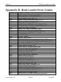
APPENDIX B: BOOT LOADER ERROR CODES................................................................................... 49
APPENDIX C: LICENSING...................................................................................................................... 51
GHI Electronics, LLC.
3 of 51
User Manual
USBwiz™
USB Devices Made Accessible
1. USB Bus
1.1. Introduction
Universal Standard Bus (USB) dominates when it comes to peripheral’s interfaces. From
a mice and keyboards to printers and external hard drives, most utilize USB interface. As
any other protocol, USB has its positives and negatives. On the positive side, USB is
designed for hot swappable devices. This means you can connect or disconnect any
device at any time. Also, you can have up to 12 8 devices connected at the same time to
one host. On the negative side, USB is not easy to add to a product. From the complexity
of the hardware to the many issues that need to be addressed for the software. For more
info, check out www.usb.org
1.2. USB, One Host and Multiple Devices!
If you ever noticed, all USB devices connect to the PC but they don’t connect to each
other (not counting USB OTG). USB protocol runs on a pyramid base. The PC is the top
of the pyramid and the devices connect to the PC directly or multiple devices can connect
to a HUB and the HUB will connect to the PC. So, on a USB system there is one and only
one HOST (your PC) and one or more device(s).
Adding a USB device to a product can be simple by using one of the USB<->UART chips.
FTDI www.ftdichip.com offers one of the most popular USB<->UART chips. This is on the
hardware side but what about software and drivers. FTDI offers drivers for multiple
operating systems as well. That is all great but about adding a host? When adding a USB
device chip to your product, your product will be able to connect to a PC. Now, what if you
want to use any USB device with your product? To connect a USB-printer to your product
you need a USB host. Before, there wasn’t any easy or efficient way to add a USB host to
a product. Most USB hosts run on PCI bus and required a full operating system to run it.
Some vendors introduced hosts that run on ISA bus but even with ISA, a little
microcontroller as PIC or AVR can’t run the USB host stack affectively. USBwiz solves the
USB host problem.
1.3. In short, what is USB?
1.3.1. USB 101!
The USB specification manual is hundreds of pages! We will try to simplify it in few
points:
Every USB Devices has at least one Configuration Set which logically contains at
least one interface.
Every interface contains Endpoints. Those Endpoints are the main elements in
USB (client-host) communication.
Endpoints are used to opening logical channels, which are called Pipes. The host
software uses pipes to communicate with devices.
GHI Electronics, LLC.
4 of 51
User Manual
USBwiz™
USB Devices Made Accessible
Configurations, Interfaces, Endpoints are described in Descriptors in every USB
Device.
There is only one endpoint that has no descriptor with is Endpoint 0. This one is a
common endpoint that is available in every USB device and opening a pipe to this
endpoint is important for USB deriver to control the device, since standard, class,
vendor specific requests are transferred on this pipe.
USBwiz takes the role of USB host driver and provides the functions to fully
control USB devices and can manage multiple pipes simultaneously.
1.3.2. Transfer Speeds
USB 2.0 defines three different transfer speeds according to Device:
Low-Speed devices with speed of 1.5 Mbps which include keyboards, mice,
joysticks and other devices that does not require high transfer data rate.
Full-Speed devices with speed of 12 Mbps. For example: Flash disks,
Communication devices and others. This is the highest speed supported by
USB1.1.
High-Speed devices with speed of 480 Mbps, which is defined in USB 2.0
Specification only. High-Speed is more suitable for Disks, Communication devices
and video devices. High-Speed devices are required to be backward compatible
with USB1.1; therefore, supporting Full-Speed.
Since USBwiz drives USB 1.1 Host Controller, so it supports Low-Speed and
Full-Speed only and capable of running High-Speed devices in Full-Speed
compatibility mode.
1.3.3. Transfer Types
There are 4 types of data transfer which are classified in a way to suit the most
common cases of communication between the host and the clients:
Control Transfers: They are used to get information from or send commands to
USB devices. Control Transfers are sent to Endpoint 0. Some Requests are
Standard and required by every USB device. Requests can be Device Request,
USB class-specific requests or Vendor-specific requests.
Bulk Transfers: Large data blocks are transferred using Bulk Transfers. There is
no guarantee on when the data will be transferred but data integrity is guaranteed
through CRC calculations. It can be used for sending data to printer or thumb Flash
devices.
Interrupt Transfers: Basically, Interrupt Transfers are “small” Bulk transfers that
guarantee timing. It is the responsibility of the software to constantly read Interrupt
Pipes periodically. Interrupt pipes are used in mice, keyboards for example.
Isochronous Transfers: When data integrity is not important but speed must be
guaranteed, Isochronous Transfers are used. For example, USB sound cards don’t
GHI Electronics, LLC.
5 of 51
User Manual
USBwiz™
USB Devices Made Accessible
care if a value was received incorrectly as, in most case, the user wouldn’t notice it.
But, it is very important that the sound card receives the data continuously.
USBwiz supports Control, Bulk and Interrupt Transfers.
GHI Electronics, LLC.
6 of 51
User Manual
USBwiz™
USB Devices Made Accessible
2. From USBwiz V1 to USBwiz V2
This section is related only to users who have experience with USBwiz version 1. USBwiz
V1 was a great success for over a year. Knowing exact customer needs helped us define
the new version of the firmware. The new firmware will load on any USBwiz chip without
anything special. There is no need to make any change on your current circuit board
designs but you may want to add the new pins if needed, for example, the SD card detect
pin. For firmware version 2.xx, we provide a full ‘C’ library that does all the work for you.
Note that updating the firmware will not update the boot loader. There will be a separate
document explaining how to update the boot loader.
GHI Electronics, LLC.
7 of 51
User Manual
USBwiz™
USB Devices Made Accessible
3. What is USBwiz?
3.1. Introduction
USBwiz is a single chip that performs all work needed for USB hosting and FAT file
system. USBwiz connects to a USB host (ISP1160) one side and to your product on the
other side (PIC, AVR…etc.) Using simple commands over I2C, SPI or UART (serial) you
can talk to almost any USB device on the market. If the device falls under a supported
USB class, no USB knowledge is necessary, USBwiz does the work. This includes many
of-the-shelf devices such as mouse, keyboard, joystick, USB memory, printers, modems
(cell phones), Wi-Fi 802.11 and many more!!
USBwiz includes FAT file system. Microsoft’s FAT file system allows your product to
create files on a media card (SD or MMC) or on a USB storage device (thumb drive or
external hard drive.) Finally, there is away for your product to read files from USB thumb
drives!
3.2. Supported USB Client Classes
The USB organization defines many classes for different USB devices. This means all
USB devices of a certain type; keyboards for example, should run the same way. This is
the reason why you do not need to install drivers when connecting a mouse to your PC.
Your operating system includes the “USB class drivers” USBwiz comes with many USB
class drivers. If a class is not supported by USBwiz, you can still use it by accessing the
raw USB commands.
USB supported Devices:
Most Human Interface Devices (HID) such as mouse, keyboard and joystick.
Printers with plain ASCII support.
Mass Storage. (Thumb drives and external USB hard drives)
Communication (Modems and cell phones) that contain Abstract Control Mode
Subclass Interface like Nokia Cell phones
Ralink Tech. Wi-Fi 802.11 USB devices with Ralink Tech chipset. (Not a standard
class and still under development)
3.3. Key Features
FAT32, FAT16 and FAT12 support.
Multi Media Card (MMC) and Secure Digital (SD) memory cards.
USB host stack and raw access to USB devices.
HID USB class support.
Printer USB class support.
Mass storage USB class support.
Supports ISP1160
Easily used with any microcontroller including PIC, AVR, Zilog…etc.
Runs with simple robust protocol on UART, I2C or SPI.
GHI Electronics, LLC.
8 of 51
User Manual
USBwiz™
USB Devices Made Accessible
UART runs as high as 921.6 K-baud, I2C up to 400kbps, and SPI clock is up to 7
MHz.
Field upgradeable firmware.
Firmware can be updated from a file on the connected media!
Built in RTC (Real Time Clock)
Very few external components are needed.
Small LQFP 64 package.
40 to 50 mA, power consumption with capability of power down.
Single supply 3.3V.
5V tolerant I/O pins.
-40˚C to +85˚C temperature operating range.
Lead free.
3.4. Some Example Applications
Digital camera.
Data Logger.
Picture viewer.
USB thumb-drive MP3 player.
Digital camera.
Automated machine.
Keyboard/mouse/joystick interface.
RS232 to “USB-printer” server
Automated SMS Sending.
GHI Electronics, LLC.
9 of 51
User Manual
USBwiz™
USB Devices Made Accessible
4. Pin-Out and Description
Pin
1
Name
UH_RD#
2
3
4
5
6
7
8
9
10
11
12
13
14
15
16
17
18
19
UH_WR#
RTXC1
D11
RTXC2
VSS
V3A
D10
MISC
UH_RESET#
A0
D9
MISC1
MISC2
SD_DET
D8
SD_CS#
VSS
UART_TX
SPI_DATARDY
I2C_DATARDY
20
21
TRST#
UART_RX
SPI_BUSY
22
23
24
25
26
27
28
I2C_BUSY
I2C_SCL
VCC
RTCK/DBG#
VSS
I2C_SDA
MMC/SD_SCK
MODE0
29
MMC/SD_MISO
GHI Electronics, LLC.
Description
Read strobe. Used for USB host chip (must have a pull-up
resistor on this pin or UH_CS#)
Write strobe. Used for USB host chip
32KHz crystal for RTC
Data line 11. Used for USB host chip
32KHz crystal for RTC
Connect to ground
Analog supply source 3.3V
Data line 10. Used for USB host chip
For future expansion (Can be Analog in or out)
Reset pin. Used for USB host chip
A0. Used for USB host chip
Data line 9. Used for USB host chip
Currently not used
Currently not used
Detects if SD card. Edge sensitive signal
Data line 8. Used for USB host chip
Chip select line for MMC or SD card
Connect to ground
In UART mode this is the transmit pin
In SPI and I2C modes, this flag indicates that USBwiz has
data ready in SPI or I2C buffer and master must read it.
USBwiz will ignore any incoming command when this pin is
high.
Leave Unconnected
In UART mode this is the data receive pin
In SPI and I2C modes, this pin is a flag that indicates that
USBwiz is busy and it will not accept any commands
The SCL line for I2C bus
3.3V power pin
Leave unconnected
Ground power pin
The SDA line for I2C
Clock signal for MMC and SD memory cards
Together with MODE1, select the interface mode for
USBwiz
Data signal from MMC or SD memory cards. Pull-up
resistor is required on this pin
10 of 51
User Manual
USBwiz™
USB Devices Made Accessible
30
31
32
MMC/SD_MOSI
SD_WP
MODE1
33
34
35
36
37
38
39
40
41
D0
D1
D2
D15
D3
D4
D5
D14
D6/BL#
42
43
44
45
46
47
48
49
50
51
52
53
VSS
V3
D13
D7
UH_IRQ
SPI_SCK
D12
VBAT
VSS
V3
TMS
SPI_MISO
54
UART_RTS
SPI_MOSI
In UART mode, this pin is Ready To Send Signal
In SPI mode, this pin is data input to USBwiz on SPI bus
55
56
57
UART_CTS
SPI_SSEL#
TCK
USBwiz_RESET#
58
UH_CS#
59
60
61
62
63
64
VSSA
TDI
XTAL2
XTAL1
VREF
TDO
In UART mode, this pin is Clear To Send Signal
Select line for USBwiz in SPI mode
Leave unconnected
Reset signal for USBwiz. USBwiz reset is required after
power up
Chip Select. Used for USB host chip (must have a pull-up
resistor on this pin or UH_RD#)
Analog Ground
Leave unconnected
Connect to 14.7456Mhz crystal
Connect to 14.7456Mhz crystal
3.3V reference for analog inputs
Leave unconnected
GHI Electronics, LLC.
Data signal to MMC or SD memory cards
SD write-protect detect
Together with MODE0, select the interface mode for
USBwiz
Data line 0. Used for USB host chip
Data line 1. Used for USB host chip
Data line 2. Used for USB host chip
Data line 15. Used for USB host chip
Data line 3. Used for USB host chip
Data line 4. Used for USB host chip
Data line 5. Used for USB host chip
Data line 14. Used for USB host chip
Data line 6. This line MUST be high at USBwiz power up
and reset. Make sure it has pull-up resistor
Ground
VCC power
Data line 13. Used for USB host chip
Data line 7. Used for USB host chip
IRQ. Used for USB host chip
Clock for SPI bus
Data line 12. Used for USB host chip
Optional 3V battery to run the RTC
Ground
3.3V power pin
Leave unconnected
In SPI mode, this pin is data output from USBwiz on SPI
bus
11 of 51
User Manual
USBwiz™
USB Devices Made Accessible
5. USBwiz Boot Loader
5.1. General Description
The boot loader is used to update the firmware of USBwiz. The firmware is the code that
sits inside the USBwiz chip and does all the work. When there is a new firmware release,
you can simply download the file from our website and, using simple commands, you can
load it on USBwiz. At power up, USBwiz will send ‘B’ and ‘L’ indicating that the boot
loader is ready to load new file. To exit the boot loader and start USBwiz firmware, send
‘R’ character. If USBwiz detects invalid firmware it returns ‘BL’ again. In such case,
reprogramming USBwiz is required.
5.2. Using the Boot Loader
The easiest way to update USBwiz is by placing the new firmware on a SD card or a USB
mass storage device. Then, connect the media to USBwiz and send the boot loader a
command to load the new firmware. The file MUST be placed in the root directory, not in
any folder. We recommend formatting the media first. If needed, user can update the new
firmware by sending it over SPI, I2C or UART. All commands return ‘!‘ followed by the
error number, !00 means no error. The boot loader responds with ‘Wxx(CR)’ on every
sector write, where xx is the sector number.
5.3. Boot Loader Commands
Command
R
LQUx
Use
Load and run USBwiz
firmware
Load firmware file from
connected media
W
Write one sector to internal
FLASH
V
Returns the loader version
Notes
If Boot loader return BL then
reprogramming USBwiz is required
The x is the drive letter. For example
LQUA will load the firmware from
MMC/SD card and LQUB will load the
firmware from the first Logical Unit
(LUN) of the attached USB mass storage
device on port 0 or port 1
Follow ‘W’ by the sector number then 512
bytes of sector data. Transaction must be
terminated by a checksum byte.
Checksum byte is calculated by adding
all 512 data bytes
Returned value is ASCII
Note: The boot loader is entirely separate program that loads USBwiz firmware. The
version number of the boot loader may not mach the version number of USBwiz.
Important Note: New USBwiz chips come with no firmware on them.
GHI Electronics, LLC.
12 of 51
User Manual
USBwiz™
USB Devices Made Accessible
5.4. Boot Loader Error Codes
The boot loader error codes are not the same as USBwiz error codes. Appendix B lists all the
boot loader error codes.
GHI Electronics, LLC.
13 of 51
User Manual
USBwiz™
USB Devices Made Accessible
6. Commanding with USBwiz
6.1. Selecting an Interface
USBwiz uses UART, SPI or I2C to communicate with any external microcontroller. At
power up, USBwiz samples MODE0 and MODE1 to determine what interface to use. The
MODE pins have a built in pull up resistors to default the pin to 1. Do not connect these
pins to VCC, leave unconnected for 1 or connect to GND for 0.
MODE0
0
1
0
1
MODE1
0
0
1
1
Interface
Don’t USE
I2C
UART
SPI
USBizi (special version and not for public) samples SPI_SCK and SPI_SSEL# to
determine what interface to use.
The following table describes the states
SPI_SSEL#
0
0
1
1
SPI_SCK
0
1
0
1
Interface
UART
Skip boot loader*
I2C
SPI
* This mode will run in UART mode but if the firmware is valid, the boot loader will automatically run the
firmware (executes ‘R’ command on its own)
6.2. UART Interface
In UART mode, UART_TX pin is used to send data/responses to your microcontroller and
UART_RX pin to receive commands/data from your microcontroller. The default baud rate
for UART is 9600 baud, 8-bit, no parity and 1 stop bit. USBwiz can be set to different baud
rates.
CTS and RTS lines must be used in high band width applications. CTS pin is an input to
USBwiz. When it is high USBwiz will not send data and will wait for CTS to go low. CTS
should be high as long as possible to not slow down USBwiz. RTS pin is an output from
USBwiz and it is set high when USBwiz FIFO is near full. Depending on data transfer
speed, RTS pin may never go high because USBwiz is contentiously emptying the FIFO.
Note: The internal UART has hardware TX FIFO that is 16 byte long. After asserting CTS,
USBwiz may still send the internal FIFO, up to 16 bytes.
Important: USBwiz will NOT send any data if CTS pin is high! If this pin is not used
then it must be connected to ground.
GHI Electronics, LLC.
14 of 51
User Manual
USBwiz™
USB Devices Made Accessible
6.3. SPI Interface Mode
In SPI mode six pins are used for communication to implement slave SPI, including two
pins for handshaking. SPI_SSEL, SPI_SCK, SPI_MISO, and SPI_MOSI are the standard
SPI pins where SSEL is used for Slave Select, SCK is the Serial Clock (7Mhz running and
1.75Mhz for boot loader,) MISO is the data line going from USBwiz to your
microcontroller, and MOSI is the data line going from your microcontroller to USBwiz. The
other two pins are used for handshaking, they are DATARDY and BUSY. DATARDY pin
goes high when there is data in the USBwiz’s SPI buffer. When BUSY is high a user must
not send any new data to USBwiz.
The boot loader in SPI is half duplex. When DATARDY pin is high, USBwiz will not
accept any commands and will assume the SPI transaction is for reading the data;
therefore, the incoming data will be discarded. The other handshaking pin is BUSY.
Before sending any command to USBwiz this pin must be checked and data can be sent
only when BUSY pin is low.
On the other hand, the firmware runs SPI in full duplex mode. When SPI is full duplex,
USBwiz will accept any incoming data while it is sending simultaneously. If USBwiz has
no data to send back, it will send NDT (No Data Token.) The NDT is 0xff and is
completely ignored by USBwiz and should be ignored by your system as well. When
reading data from USBwiz but there is nothing to send, use NDT.
In some rare cases, there could be a need to send 0xFF (writing the hex value 0xFF, not
ASCII 0xFF!!) This is resolved by using HDT (Half Data Token.) HDT is the value 0xFE.
Whenever USBwiz or your system sees HDT, it must wait for one more byte to decide
what that value actually is. HDT followed by another HDT results in 0xFE; otherwise, it is
0xFF. Keep in mind 0xFF is always ignored even if it came after HDT.
Here is a simple ‘C’ code example:
void SendSPItoUSBwiz(int8 c)
{
if( c = = 0xFF )
{
PutSPI(0xFE);
PutSPI(0x00);
}else if( c = = 0xFE )
{
PutSPI(0xFE);
PutSPI(0xFE);
}else
PutSPI(c);
}
Note that this example ignores the incoming data from SPI and it shouldn’t be used.
Please consult the code library we provide.
Important: USBwiz requires the following in order for SPI to work:
SCK is output from your system.
SCK is idle high.
GHI Electronics, LLC.
15 of 51
User Manual
USBwiz™
USB Devices Made Accessible
SCK is lower that 7Mhz. (1.75 in boot loader)
Data is shifted out MSB first.
Data is shifted on the rising edge.
6.4. I2C Interface Mode
Four pins are needed for I2C communication. The USER_I2C_SCL and USER_I2C_SDA
are the two I2C bus lines. I2C_DATARDY and I2C_BUSY lines work exactly the same
way as SPI_DATARDY and SPI_BUSY work. USBwiz runs in slave I2C mode always.
The slave address of USBwiz is 0xA4. This address is fixed and can’t be changed.
GHI Electronics, LLC.
16 of 51
User Manual
USBwiz™
USB Devices Made Accessible
7. USBwiz Functions
The commands and response in USBwiz are made in a way where they can be understood
and read by a human and can be easily parsed by any simple 8-bit micro. Each command is
2 characters. Some commands take parameters and others don’t. For example, VR
command doesn’t take any parameters and it returns the version number. On the other hand,
MD requires parameter to run. MD creates (makes) a folder on the accessed media device.
‘MD LOG’ creates a folder with the name LOG.
Also, every command must be terminated with Carriage return. This is the enter key on your
keyboard. When programming in ‘C’, it is ‘\r’ or 0x0D.The backspace key is supported in case
there is a need to discard the last entry. There are many restrictions that must be noticed or
USBwiz will not accept the command.
Commands must be 2 characters.
Every command must have the exact number of arguments.
Spaces must be used whenever is required.
Extra spaces count as errors.
All numbers are hexadecimal.
7.1. FAT Storage Media
USBwiz can connect to two kinds of storage media types. The media types are SD/MMC
cards and USB Mass Storage device (SCSI command subclass, bulk only protocol) which
includes thumb flash, USB hard drives and card readers. USBwiz supports 3
simultaneous FAT devices. Keep in mind that all devices must be formatted FAT12,
FAT16 or FAT32.
USBwiz can mount up to 3 File System Medias that are independent from each other,
which means that all opened files and operations in one file system has no effect on the
others. This gives USBwiz very great capability of flexible switching between the file
system Medias and providing other valuable functions like reading from file in one Media
and write it back in other file in another media at the same time.
To access FAT Storage Media, Storage device low level driver must be attached by AM
command then File System can be mounted by MU command. Then SS command is
used to switch between the file systems. Check AM, MU and SS commands for more
details.
Example: Mount File System 0 on MMC:
AM C
!00
MU 0>C
!00
SS 0
!00
MD FOLDER
!00
GHI Electronics, LLC.
17 of 51
User Manual
USBwiz™
USB Devices Made Accessible
USBwiz supports the original FAT file system where files are 8 characters long with
extension that is 3 characters long. No long file name is supported. This allows us to
speed up the file access time and simplify the user’s work.
7.1.1. Directories (folders)
Folders are supported by USBwiz. And it is possible to move over Folders by CD
command.
User must be sure about the current folder that is working in be cause there is no
current way to retrieve the current location in folder tree
MD USBwiz this command will create “USBwiz” folder
7.1.2. Files
Files can be opened for read, write or append. Opening a file for read requires that the
file exists on the media. Opening a file for write requires that the file doesn’t exist on
the media. If the file that is being open for read already exists on the media, USBwiz
will erase the old folder. Opening a file for append will add data to a file if it exists. If
the file doesn’t exist then a new file will be made. With USBwiz you can open up to 4
files at the same time using file handles.
Handles are used for fast access to a file. If a user needs to log data to 2 files at the
same time, “VOLTAGE.LOG” and “CURRENT.LOG” file handles become very useful. To
do so, open VOLTAGE.LOG under handle 1 and CURRENT.LOG under handle 2.
Now start sending your data to handle 1 and 2 instead to the file name.
7.2. USB Mass Storage
USBwiz has an internal USB Mass Storage Driver that can control two Mass Storage
Devices at the same time. UM Command is responsible for the manual Registering of
USB Devices as Mass Storage Devices after enumerating it by UI command. Then comes
the role of AM to attached Storage IO Driver then the MU command to Mount the file
system on, then it is ready to open, close, manipulate data on.
To access USB mass storage Device, some initialization commands must be
performed before which will be clarified in the following example:
Let’s Say that a Four-LUN Card Reader is connected to USB port 0. to access card
connected to this Reader at the 1st LUN – i.e. logic drive B -, the following procedures
must be performed:
First, this USB Card Reader must be enumerated like any other USB device. We will
initialize it to USB device handle 0
UI 0>0
Second, Mass Storage Driver must be initialized to take care of this card reader using
UM command. Here we assign this device to Mass Storage Device Handle 0.
UM 0>0
!00
GHI Electronics, LLC.
18 of 51
User Manual
USBwiz™
USB Devices Made Accessible
$03
!00
Where 03 is the last LUN order.
Now the Card reader is ready to accept Attach command AM and mount the file
system MU.
Suppose that File System 0 is already mounted for MMC
AM U0<2 // mass storage handle 0 and attach the third LUN
!00
MU 1<U0 // Mount the second File System on the mass storage of mass storage handle 0
!00
SS 1
!00
MD TEST
!00
SS 0
!00
CD FOLDER
!00
Note: the previous initialization processes is required to perform only once, after
connecting the mass storage device.
7.3. USB Human Interface Device
This USB class includes vast range of HID devices. USBwiz HID driver support those that
has only output interrupt Endpoint for HID Report sending.
To access HID:
First, this HID must be enumerated like any other USB device. We will initialize HID
which is Attached to USB port 1, to USB device handle 0 as an example
UI 1>0
Second, HID Driver must be initialized to take care of this HID using the registering
command and USB pipe must be chosen to access the Output Endpoint.
UH 0>3
Then USBwiz will output Data size that is send by the HID which is 4 Bytes for Mice
and 8 Bytes for Keyboards. Now the USBwiz is ready get Data from HID which can be
performed by Read HID Pipe
RH 3
Note: the previous initialization process is required to perform only once after
connecting the mass storage device.
GHI Electronics, LLC.
19 of 51
User Manual
USBwiz™
USB Devices Made Accessible
7.4. USB Printers
USBwiz Printer driver support those that has Interface that has unidirectional protocol and
accepts pure ASCII similarly to Parallel Port Printers. About 60% of USB printers out there
support the previous requirements.
To access Printer:
First, this Printer must be enumerated like any other USB device. We will initialize HID
which is Attached to USB port 1, to USB device handle 0 as an example
UI 1>0
Second, Printer Driver must be initialized to take care of this Printer using the Register
Printer Command UP.
UP 0
Now, the USBwiz is ready Send Data to the printer, which can be performed by Print
Data Command UPP.
PP F4
Get Printer Status Command PS is used to Get Printer Standard Status Byte which is
identical to status byte that is usually returned from Parallel Port, check PS command
for more information
USBwiz also provides Reset Printer Command PR.
7.5. USB Communication Device
Communication Device could be under standard USB class CDC 02 or a special vendor
defined device. USBwiz currently support CDC device that have Interface that has
Abstract Control Model Subclass 02 which accepts pure ASCII similarly to hyper terminal
program on COM Port. So User can Send AT Command and receive response by means
of this Driver. About 80% of Cell Phones support this Subclass like Nokia or Motorola Cell
phones.
To access Communication Device:
First, Communication Device must be enumerated. Supposing that the device is
attached to USB port 1, to USB device handle 0 as an example
UI 1>0
Second, the driver must be initialized to take care of this device using the Register
Communication Device Command UA.
UA 0
Now, the USBwiz is ready exchange Data with the device, which can be performed by
RA and WA commands.
Example: Nokia Cell phone is connected to port 0
UI 0>0
!00
GHI Electronics, LLC.
20 of 51
User Manual
USBwiz™
USB Devices Made Accessible
UA 0
!00
WA 3
AT
!00
RA
!00
$03
AT
!00
RA
!00
$06
OK
!00
7.6. FTDI Device
FTDI is a very popular USB to UART chip. USBwiz has a driver to drive this chip and set
its serial port parameters like Baud rate. And user can send data to that serial port by WQ
and receive by RQ.
To FTDI Device:
First, Communication Device must be enumerated. Supposing that the device is
attached to USB port 1, to USB device handle 0 as an example
UI 1>0
Second, the driver must be initialized to take care of this device using the Register
Communication Device Command UQ.
UQ 0
Now, the USBwiz is ready exchange Data with the device, which can be performed by
WQ and WQ commands.
Of course, User must set the right parameters for the serial port through the following
commands: BQ, DQ and FQ
Example:
FTDI device with the default PID and VID is connected to port 0
UI 0>0
!00
UQ 0
!00
BQ 4138
WQ 6
Hello
!00
GHI Electronics, LLC.
// baud rate 9600
21 of 51
User Manual
USBwiz™
USB Devices Made Accessible
RA
!00
$03
Hi
!00
7.7. USB Ralink Wi-Fi 802.11
Not Supported yet. We hope to have the driver ready in 4Q/2006
7.8. Raw USB Access
Accessing any USB device has been divided into 3 stages:
1. Enumeration stage which includes USB addressing.
2. Learning Stage and querying about USB device stage which includes also
opening the required Pipes + sending setup commands on the default control pipe.
3. Read or write Pipe stage + sending setup commands on the default control pipe
too.
Example on accessing a USB mouse:
Stage 1
Assign Device handle 0 for device connected on port 0
UI 0>0
Output: nothing if no error
Stage 2
Load Device descriptor into the internal Buffer
LD 0>D
Output: nothing if no error
It is optional command, since it is just to display internal buffer contents
DB A
Output: Device descriptor size + Device descriptor data in the internal buffer
Load the first configuration descriptor into the internal buffer
LD 0>C0
Output: nothing if no error
It is optional command, since it is just to display internal buffer contents
GHI Electronics, LLC.
22 of 51
User Manual
USBwiz™
USB Devices Made Accessible
DB A
Output: configuration descriptor size + configuration descriptor data in the internal
buffer.
Set desired configuration which is the first configuration
SC 0>1
Note that 0 means go back to addressing mode stage.
Find specific Interface Descriptor in the previously loaded Config Descriptor in the
internal buffer.
FI 03 01 02 00
class =HID, subclass=bootable, protocol=mouse, index=the 1st found interface
descriptor that match this criteria.
Output: The found interface descriptor size + the data
Or It is possible can do the following:
FI 03 FF FF 00
class=HID subclass=don't care protocol=don't care index=the 1st found interface
descriptor that match this criteria.
Output: The found interface descriptor size + the data. Which is the same result if the
device is USB mouse with no other HID interfaces?
Set the Found Interface
SI
Output: nothing if no error
Find specific Endpoint that belongs to the previously found Interface
FE 03 02
transfer= interrupt direction= input
Output: found Endpoint descriptor size + the data
Open Pipe to the found endpoint to the handle 6.
OP 6
It is possible to search for any kind of descriptors in the loaded internal buffer using FD
command
GHI Electronics, LLC.
23 of 51
User Manual
USBwiz™
USB Devices Made Accessible
Example: Find the 1st HID descriptor in a previously loaded configuration into the
internal buffer.
FD 21 00
Output:
!00
$09
09 21 10 01 00 01 22 34 00
!00
Stage 3
Read 4 bytes from Pipe 6
RP 6 04
Close Pipe
CP 6
Using Setup command and Find Descriptor Command:
It is possible to send setup requests on the default control pipe using SR command
Example: Get Device descriptor
SR device_handle>80 06 0100 0000 0012
Output:
0x12 0x01 0x10 0x01 0x00 0x00 0x00 0x08 0x2A 0x06 0x00 0x00 0x00 0x00 0x00
0x00 0x00 0x01
GHI Electronics, LLC.
24 of 51
User Manual
USBwiz™
USB Devices Made Accessible
8. USBwiz Commands Set
All commands below are entered in ASCII. We choose to use ASCII to simplify
troubleshooting and to allow humans to enter commands easily. A special case is when
accessing the data inside or outside a file. When writing/reading to/from a file or USB Pipe,
USBwiz will use any kind of data. Basically, what you send is what goes on the file. It doesn’t
have to be ASCII.
When USBwiz is done processing a command, it will return an error code in the form
“!xx<CR>” where xx is the error number. Also, some commands require returning some extra
information. Returned data will come after the symbol $, unless noted otherwise.
You can send multiple commands to USBwiz until its FIFO is full (indicated by BUSY or
RTS.) USBwiz will take the commands in one at the time, process them and send responses
for each one. Always terminate commands with carriage return character.
Note: in all commands descriptions of their outputs will consider the successful executing of
the command
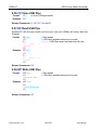
8.1. VR Get Version Number
It prints the version number of USBwiz firmware. Note that this version is not same or
related to the version number of the boot loader. The return value is always in the form
“USBwiz x.xx”
Format:
VR
Example: VR
8.2. BR Set UART Baud Rate
UART defaults to 9600 at power up. This is extremely slow but some systems don’t
support faster bauds. The baud rate can be set to many different standard baud rates. BR
command sets the internal divider registers of the UART hardware. This way any possible
baud rate can be set. To calculate the divider value use (OSC*4/BaudRate/16) The OSC
we use on USBwiz is 14745600. The baud rate value is lost on reset and UART goes
back to 9600.
Format:
BR vvvv
vvvv: WORD HEX Baud Rate Divider
Example: BR 0020 Baud Rate is 115200
Some common values:
Baud Rate
9600
19200
38400
57600
GHI Electronics, LLC.
Divider in decimal
384
192
96
64
25 of 51
Divider in HEX*
0180
00C0
0060
0040
User Manual
USBwiz™
USB Devices Made Accessible
115200
921600
32
4
0020
0004
* To be used with BR command
8.3. AM Attach Storage Device “Storage Media”
This command is simple and important. It prepares USBwiz to communicate with the
Storage media at Sector Level IO and check the availability of this media. Usually it
prompted just before MU command and after UM command for USB Mass Storage
Device
AM C
Attach SD or MMC.
AM Um<n
Attach USB Mass Storage Device, Where m is order of the preRegistered USB Mass Storage Handle, and n is the LUN order
which is usually zero for thumb flash drives.
Example: AM U0<0
Attach Thumb Flash that is registered on handle 0 and use the
first LUN which order’s is zero
Format:
Related commands: MU, SS, UI and UM
8.4. RS Read Sector
Format1:
RS ssssssss
!00
512 Bytes is
returned
!00
Example1: RS 0
Format2:
RS C>ssssssss
RS Um>ssssssss
Read Sector from the current File System Media
ssssssss HEX DWORD sector address
Read Sector 0
Read Sector from Specific Attached Media even
m is Mass Storage Device Handle
ssssssss HEX DWORD sector address
!00
512 Bytes is
returned
!00
Example2: RS U0>1
Read Sector 1 from attached USB Mass Storage
Device Media to Mass Storage Handle 0
8.5. WS Write Sector
Format1:
WS ssssssss
!00
512 Bytes must be
sent to USBwiz
GHI Electronics, LLC.
Write to Sector from the current File System Media
ssssssss HEX DWORD sector address
26 of 51
User Manual
USBwiz™
USB Devices Made Accessible
!00
Example1: WS 0
Format2:
Write to Sector 0
WS C>ssssssss
WS Um>ssssssss
Write to Sector from Specific Attached Media even
m is Mass Storage Device Handle
ssssssss HEX DWORD sector address
!00
512 Bytes must be
sent to USBwiz
!00
Example2: WS U0>1
Write to Sector 1 from attached USB Mass Storage
Device Media to Mass Storage Handle 0
8.6. MU Mount File System Media
USBwiz can mount up to 3 File System Medias that are independent from each other,
which means that all opened files and operations in one file system has no effect on the
others. This gives USBwiz very great capability of flexible switching between the file
system Medias and providing other valuable functions like reading from file in one Media
and write it back in other file in another media at the same time.
MU takes the responsibility of mounting the dedicated File System to the dedicated PreAttached device. Attached Device could be MMC/SD and one or two USB Mass Storage
Devices simultaneously. Always use SS command after the use of MU to switch between
mounted file systems. The file handles will be closed after executing MU command.
Format:
MU m>C
Mount File System with order m to SD or MMC.
MU m>Un
Mount File System with order m to USB Mass Storage Device
Handle n
Example: MU 0>C
MU 1>U0
File System 0 is dedicated for SD or MMC
File System 1 is dedicated for the USB Mass Storage Device
handle 0
Related Commands: UI, UM, AM and SS
8.7. SS Switch between File System Medias
Switch Media command switch the file access to different File System Medias. The media
must be already mounted. This command doesn’t close any opened file handles and it is
possible to switch between the Medias at any time.
Format:
SS m Switch to File System Media m
Example: SS 2
Switch to File System Media 2
Related Commands: UI, UM, AM and MU
GHI Electronics, LLC.
27 of 51
User Manual
USBwiz™
USB Devices Made Accessible
8.8. MS Get Media Statistics
Format: MS
!00
$ssssssss $ffffffff
!00
ssssssss HEX DWORD Media Size
ffffffff HEX DWORD Free Size
8.9. QF Quick Format Media
This command resets File Allocation Only. No change occurs to Boot Sector or MBR
Format: QF CONFIRM FORMAT
Note: the function will not be executed till the right confirming string follows the command
8.10. IL Initialize List Files and Folders
It sets List Files and Folders Function pointer to the first Directory entry in the current root.
Format:
IL
Example: IL
Related Command: NF
8.11. NF Get Next Directory Entry
This command will print out the Directory Entry “File or Folder” and increments List Files
and Folders pointer.
Format:
NF
!00
NNNNNNNN.EEE AA ssssssss
!00
Example: NF
!00
TEST0001.TXT 00 0000FE23
!00
NF
!00
TEST0002.TXT 00 00001234
!00
NNNNNNNN File Name
EEE File Extension
AA HEX Byte File Attributes*
ssssssss HEX DWORD File Size
Passing NF command two times and
get the results.
Related Command: IL
* File Attributes are one byte Standard Attribute Structure in FAT system.
7
6
5
4
3
2
2
0
Reserved Archive Folder Volume ID System Hidden Read Only
8.12. MD Make Directory
Creates a folder
GHI Electronics, LLC.
28 of 51
User Manual
USBwiz™
Format:
USB Devices Made Accessible
MD foldername
foldername follows the short name formation
Example: MD MYFOLDER Create a folder with name MYFOLDER
8.13. CD Change Directory
Changes the current folder access. Folder must exist.
Format:
CD foldername
Foldername follows the short name formation
Example: CD MYFOLDER The current root is in MYFOLDER
8.14. RD Remove Directory
This command removes Directory. The directory must be empty from any files or
subdirectories.
Format:
RD foldername
Foldername follows the short name formation
Example: RD MYFOLDER Remove the folder with name MYFOLDER
8.15. OF Open a file for read, write or append
To open a file for read, write or append in the current Folder, use OF command. The
commands require a file handle and the access mode.
Open Modes are:
‘R’ Open for read requires the file to already exist in the current media and the current
accessed folder.
‘W’ Open for read will create a new file and give write privilege to it. If the file already
exists, it will be erased first then will open a new one for write.
‘A’ Open for append is similar to write with one exception. If the file already existed, it
will be opened and the incoming data will be appended at the end.
Important Note: The file name must be in standard short name “8.3” formation.
Note: USBwiz currently has 4 available file handles.
Format:
OF nM>foldername
Example: OF 1R>VOLTAGE.LOG
OF 0W>CURRENT.LOG
Open file foldername to file handle n with
access mode M which can be R,W or A.
Open file VOLTAGE.LOG to file handle 1 with
READ access mode.
Open file CURRENT.LOG to file handle 0 with
WRITE access mode.
Related Commands: CF, FF, RF, PF, FP, WF, RW, SP, ZF and SW
GHI Electronics, LLC.
29 of 51
User Manual
USBwiz™
USB Devices Made Accessible
8.16. CF Close File Handle
This command closes the opened file and updates file parameters in the file system and
confirm that all data in file buffer is written to the media. Then it releases the file handle to
be available for new file opening.
It is an important command, especially for file functions that add or modify on files to
confirm that data is written on the media and file parameters are updated.
Format:
CF n Close File handle n
Example: CF 0 Close File handle 0
Related Commands: OF, FF, RF, WF, RW and SW
8.17. FF Flush File Data
This command does the same function of CF function except releasing the file handle. So
it updates file parameters and flushes file buffer data into storage media and keep file
handle ready for another write command.
It is made especially for file functions that add or modify on files to confirm that data is
written on the media and file parameters are updated.
Format:
FF n Close File handle n
Example: FF 0 Close File handle 0
Related Commands: OF, CF, WF, RW and SW
8.18. RF Read from File
Sending RF with the file handle and the byte count and USBwiz will return your data. The
file must be opened for read first. To read more data from the file, send another RF. If
USBwiz couldn’t get all the data it promised to return, it will send a filler symbol instead. It
is up to the user to decide what the filler is going to be.
Format:
RF nM>ssssssss
n File Handle
M Filler Character
!00
ssssssss Bytes is ssssssss HEX DWORD desirable data size to be read
aaaaaaaa HEX DWORD actual read data from file size
returned
$aaaaaaaa
!00
Example: We have a file with 8 bytes (ABCDEFGH) in it, and it is opened for read with
handle number 2.
RF 2Z>5
!00
ABCDE
$00000005
!00
RF 2Z>5
GHI Electronics, LLC.
Read 5 bytes from a file #2 with filler Z
USBwiz accepted the command
This is the data coming from the file
All 5 bytes are valid
No errors has occurred
Read more data. We will request 5 but only 3 are left
30 of 51
User Manual
USBwiz™
USB Devices Made Accessible
!00
FGHZZ
$00000003
!00
No errors has occurred
USBwiz returned the last 3 bytes but added 2 fillers
USBwiz indicating it was able to read 3 bytes only
USBwiz no error indication
Related Commands: OF, CF, PF and FP
8.19. WF Write to File
After a file is opened for write, you can use WF to write to that file handle. After WF
command, USBwiz will respond with error code. If the error code is !00 then writing data
to the file is ready. Now, everything goes into the interface goes directly to the file with no
interpretation what so ever. After sending all requested data, USBwiz will return the actual
write count. In some instances USBwiz could fail writing all the data and it will inform the
user of the data loss. Finally, WF returns another error code. You can send as many WF
as you need to write more data to the file. We recommend sending small block of data,
around 100 bytes.
WF n>ssssssss
!00
User sends data
$aaaaaaaa
!00
Example: WF 1>10
!00
1234567890abcdef
$00000010
!00
Format:
n File Handle
ssssssss HEX DWORD desirable data size to be
written
aaaaaaaa HEX DWORD actual written data to file size
Write 16 bytes to the file opened for handle 1
USBwiz accepted the command
16 bytes of data to go into the file
USBwiz was able to write 16 bytes
No errors has occurred
Related Commands: OF, CF and FF
8.20. SW Shadow Write to multiple Files
This command is similar to WF command except that it writes the same data into two or
three files simultaneously
Format 1:
SW n m>ssssssss
!00
User sends data
$aaaaaaa1 !00
$aaaaaaa2 !00
Format 2:
SW n m o>ssssssss
!00
User sends data
$aaaaaaa1 !00
$aaaaaaa2 !00
$aaaaaaa3 !00
GHI Electronics, LLC.
N First File Handle
m Second File Handle
ssssssss HEX DWORD desirable data size to be
written
aaaaaaaa HEX DWORD actual written data to file
size
Same as the previous Format except for having a
third shadow o Third File Handle
31 of 51
User Manual
USBwiz™
Example:
USB Devices Made Accessible
SW 1 0 3>10
!00
1234567890abcdef
$00000010 !00
$00000010 !00
$00000010 !00
Write 16 bytes to the file opened for handle 1, 0, 3
USBwiz accepted the command
16 bytes of data to go into the file
USBwiz was able to write 16 bytes to the three files
successfully with no errors occurrence.
Related Commands: OF, CF and FF
8.21. RW Read from File, Write to other file
This command is very powerful and fast! If we have two files, one is opened for Read
and the other for write, this command allows copying data from a file to another even if
they were opened in different storage media devices.
Format:
RW r w>ssssssss
!00
$aaaaaaaa
!00
r Read-Mode File Handle
w Write-Mode File Handle
ssssssss HEX DWORD desirable data size to be read
and written
aaaaaaaa HEX DWORD actual written data from file
size
Example: Suppose that a file is opened for read and represented in handle 0 and
another file is opened for write and represented in handle 1.
RW 1 0>100
!00
$aaaaaaaa
!00
Read 256 bytes from file 1 and write them into file 0
USBwiz accepted the command
All 256 bytes are valid
No errors has occurred
Related Commands: OF, CF and FF
8.22. SF Split file
SF splits a file into 2 new files. The files can be opened on different drives or the same
drive. It requires one file to be open for read and 2 other files to be open for write.
Files handles will be automatically closed after successful executing of the command.
Format:
SF n>m+o@ssssssss
!00
$aaaaaaa1
!00
$aaaaaaa2
!00
N Source Read-Mode File Handle
m First part destination Write-Mode File Handle
o Second part destination Write-Mode File Handle
ssssssss HEX DWORD desirable split position in
the source file
aaaaaaa1 HEX DWORD actual written data to the
first part file
aaaaaaa2 HEX DWORD actual written data to the
second part file
Example: Suppose that the source file is represented by file handle 1 with size 32
Bytes. And we want to split it at the position 16 and save the parts into files
represented in file handles 0 and 2 which are opened in write-mode.
GHI Electronics, LLC.
32 of 51
User Manual
USBwiz™
USB Devices Made Accessible
SF 1>0+2@10
!00
$00000010
!00
$00000010
!00
Split file 1 at position 16 into two files 0 and 2
USBwiz accepted the command
USBwiz was able to write 16 bytes to the first part
No errors has occurred
USBwiz was able to write 16 bytes to the first part
No errors has occurred
Related Commands: OF
8.23. PF Seek File
This command changes the file pointer position. File must be opened in Read-Mode.
Format:
PF n>ssssssss
Example: PF 1>10
n File Handle
ssssssss HEX DWORD new position
Set file pointer at position the 16th byte in file, supposing
that its size is less than 16 bytes
Related Commands: OF and RF
8.24. FP Get Current File Pointer Position
This command gets the current sector address and the position in that sector of file
pointer. File must be opened in Read-Mode,
Format: FP n
!00
$ssssssss $pppp
!00
n File Handle
ssssssss HEX DWORD Sector address
pppp HEX WROD position in Sector
8.25. ZF Resize File
This command sets file size to a certain position less than its size and omits the data after
that position.
File must be opened in Read-Mode.
File handle will be automatically closed after successful executing of this command.
Format:
ZF n>ssssssss
Example: ZF 1>10
n File Handle
ssssssss HEX DWORD desirable data size to be written
Resize the file to 16 bytes, supposing that its original size
is less than 16 bytes
Related Commands: OF
8.26. DF Delete File
Format:
RD filename
filename follows the short name formation
Example: RD TEST.TXT Remove the file with name TEST.TXT
GHI Electronics, LLC.
33 of 51
User Manual
USBwiz™
USB Devices Made Accessible
8.27. IF Find File or Folder
This command search for a specific file or folder name in the current folder and print out
file’s major information which includes size, attributes and date & time of modification.
Format:
IF filename
!00
$ssssssss $AA $ddddtttt
!00
filename follows the short name formation
ssssssss HEX DWORD File Size
AA HEX Byte File Attributes*
ddddtttt HEX DWORD time and date
structure**
Example: IF TEST.TXT
!00
$00000F34 $00 $ 34210000
!00
File has been found and its size is 3892
bytes with no special attributes.
Last modification time is 00:00:00 date is
1/1/2006
* File Attributes are one byte Standard Attribute Structure in FAT system.
7
6
5
4
3
2
2
0
Reserved Archive Folder Volume ID System Hidden Read Only
** Time and Date structure is a DWORD Standard structure in FAT system.
Bits(s)
31..25
24..21
20..16
15..11
10..5
4..0
Field
Year1980
Month
Day
Hour
Minute
Second2
Description
Years since 1980
1..12
1..31
0..23
0..59
Seconds divided by 2 (0..30)
8.28. ND Rename File or Folder
Format:
ND filename newname
filename follows
formation
newname
formation
Example: ND TEST.TXT CURRENT.LOG
follows
the
short
name
the
short
name
Rename the file with the name
TEST.TXT with name CURRENT.LOG
8.29. UI Enumerate USB Device
It is a major command in USBwiz since it is a USB Driver function that Enumerates newly
connected USB Device and conjunct it with a logical USB Device Handle. So it is the first
step command to deal with any USB commands. Currently USBwiz supports three USB
device handles.
Format:
UI p>h
Example: UI 0>1
GHI Electronics, LLC.
p is USB port order
h is USB device handle
Enumerates the USB device connected to port 0 and conjunct it to
device handle 1
34 of 51
User Manual
USBwiz™
USB Devices Made Accessible
Related Commands: All USB commands like for instance UR, UM, UH, UA, UP…..etc.
8.30. UR Release USB Device Handle
It Releases USB Device Handle so it can be dedicated by enumeration to new device. IT
importance comes when re-enumeration of one connected device or changing the
connected device is needed.
Format:
UR h
Example: UR 1
h is USB device handle
Release USB device handle 1
8.31. UM Register USB Mass Storage Device
USBwiz has an internal USB Mass Storage Driver that can control two Mass Storage
Devices at the same time. UM Command is responsible for the manual Registering of
USB Devices as Mass Storage Devices after enumerating it by UI command. Then comes
the role of AM to attached Storage IO Driver then the MU command to Mount the file
system on, then it is ready to open, close, manipulate data on.
USB Mass Storage Device and be a Thumb Flash which usually has only one LUN –
Logical Unit - or a card Reader which has more than one LUN, one for each Card Type.
USB Floppy Disk Drives are not Supported.
Format:
UM h>m
!00
$nn
!00
Example: UM 1>0
!00
$04
h is USB device handle of an enumerated device
m is USB Mass Storage device handle - 0 or 1 nn is Last LUN Order which is usually zero for thumb flashes
Register USB device of USB device handle 1 to USB Mass
Storage handle 0
The device is 4 LUN Card Reader
!00
Related Commands: UI, UR, AM and MU
8.32. UH Register USB Human Interface Device
USBwiz has an internal Simple HID Driver that can control as many HID as required - only
one-Input HID like Mice, Keyboards and Joysticks - . UH Command is responsible for the
manual Registering of USB Devices as HID after enumerating it by UI command and
opening a certain USB Pipe to be the input channel to get HID Report which is the output
targeted data of HID. Then the role of RH command comes to read this pipe.
This command also returns HID Report Size which defines the quantity of Data that will be
returned by RH command.
Format:
UH h>p
!00
GHI Electronics, LLC.
h is USB device handle of an enumerated device
p is a free USB Pipe Handle
35 of 51
User Manual
USBwiz™
USB Devices Made Accessible
$nn
!00
Example: UH 0>3
!00
$04
!00
nn is HID Report Size
Register USB device of USB device handle 0 as HID and use
Pipe Handle 3
Report size is 4 Bytes
Related Commands: UI, UR, RH and CP
8.33. RH Read HID Report
This command read HID Report’s Data.
Format:
RH p
!00
Report’s data
!00
Example: RH
!00
Report’s Data
!00
p is an opened USB Pipe Handle by UH command.
Report’s Data may not be readable since it is not converted
to ASCII HEX Bytes, but they are returned as they came
from the Pipe.
Register USB device of USB device handle 0 as HID and
use Pipe Handle 3
Related Commands: UI, UR, UH and CP
8.34. UP Register USB Printer
USBwiz has an internal Simple Printer Driver. UP Command is responsible for the manual
Registering of USB Devices as Printer after enumerating it by UI command. Then comes
the role of PP command to send printing Data.
Currently USBwiz Printer driver support those that has Interface that has Unidirectional
protocol and accepts pure ASCII similarly to Parallel Port Printers. About 60% of USB
printers out there support the previous requirements.
Format:
UP h
Example: UP 1
h is USB device handle of an enumerated device
Register USB device of USB device handle 1
Related Commands: UI, UR, PR, PS and PP
8.35. PR Reset USB Printer
Format:
PR
Reset USB Printer
Example: PR
Related Commands: UP, PS and PP
GHI Electronics, LLC.
36 of 51
User Manual
USBwiz™
USB Devices Made Accessible
8.36. PS Get USB Printer Status
Format:
PS
!00
$nn
!00
Example: PS
!00
$20
!00
h is USB device handle of an enumerated device
p is a free USB Pipe Handle
nn is Printer Status*
Register USB device of USB device handle 0 as HID and use
Pipe Handle 3
Printer status indicates Not paper in the feeder
* Note: Some USB printers may not always able to determine Status.
Bits(s) Field
Description
7,6
Reserved
Reserved
5
Paper Empty 1= Paper Empty
0 = Paper Not Empty
4
Select
1 = Selected
0 = Not Selected
3
Not Error
1 = No Error
1 = Error
2,1,0
Reserved
Reserved
Related Commands: PR, UP and PP
8.37. PP Send Data to USB Printer to print
Format:
PP ss
!00
Data to Print
!00
ss is Byte data to be sent to printer size
Example: PP D
!00
Hello Word!
!00
Related Commands: PR, PS and UP
8.38. UA Register Communication Device
USBwiz has an internal CDC Driver. UA Command is responsible for the manual
Registering of USB Devices as CDC after enumerating it by UI command. Then the roles
of RA and WA commands come to send and receive data with the device.
Currently USBwiz CDC driver support those that has Interface that has Abstract Control
Model Subclass and accepts pure ASCII similarly to hyper terminal program on COM
Port. So User can Send AT Command and receive response by means of this Driver.
About 80% of Cell Phones support this Subclass like Nokia or Motorola Cell phones.
Format:
UA h
Example: UA 1
GHI Electronics, LLC.
h is USB device handle of an enumerated device
Register USB device of USB device handle 1
37 of 51
User Manual
USBwiz™
USB Devices Made Accessible
Related Commands: UI, UR, RA and WA
8.39. RA Read CDC Buffer
This command reads out the internal OUT buffer of the communication device.
Format:
RA
!00
$ss
ss bytes
!00
Read CDC Buffer
Data Size is HEX Byte ss
Example: RA
!00
$06
OK
!00
Note: Sometimes multiple RA commands must be passed to flush out all the data in the
buffer, like when you first get the echo of the command and the get the result of it.
Related Commands: UA and WA
8.40. WA Send Data to CDC
Format:
WA ss
!00
Data to CD
!00
ss is Byte data to be sent to printer size
Example: WA 3
!00
AT
!00
Related Commands: RA and UA
8.41. UQ Register FTDI Device
USBwiz has an internal FTDI Driver. UQ Command is responsible for the manual
Registering of USB Devices as FTDI after enumerating it by UI command.
Format1:
UQ h
Format2:
UQ h vvvv pppp
GHI Electronics, LLC.
h is USB device handle of an enumerated device
PID and VID are the default ones 0x6001 and 0x0403
h is USB device handle of an enumerated device
vvvv is Vendor ID
pppp is Product ID
38 of 51
User Manual
USBwiz™
USB Devices Made Accessible
Example: UQ 1
Register USB device of USB device handle 1
Related Commands: UI, UR, BQ, DQ, FQ, RQ and WQ
8.42. BQ Set FTDI Baud Rate
Format:
UQ bbbb
Example: UQ 4138
bbbb is Baud rate value*
Set Baud Rate to 9600 - clock is 48Mhz. -
* Some calculated baud rate values when Xtal is 48Mhz, referenced from FTDI Specifications
Baud Rate Value Actual Baud Rate
04E2
2400
0271
4800
4138
9600
809C
19200
C04E
38400
0034
57600
001A
115200
000D
230400
Related Commands: UQ, DQ, FQ, RQ and WQ
8.43. DQ Set FTDI Data Format
Format:
DQ b p s
b is bits number - typically 8 p is parity
0 no parity
1 Odd
2 Even
3 Mark
4 Space
Example: DQ 8 0 0
s is stop bit count
01
1 1.5
23
Number of bits is 8, No parity bit, one Stop bit
Related Commands: BQ, UQ, FQ, RQ and WQ
8.44. FQ Set FTDI Handshaking Mode
Format1: FQ N
No handshaking
FQ R
Hardware Handshaking using DTR/DSR lines
FQ S
Hardware Handshaking using CTS/RTS lines
Format2: FQ X NF
GHI Electronics, LLC.
Xon/Xoff Handshaking where N is Xon character and F is
Xoff character
39 of 51
User Manual
USBwiz™
USB Devices Made Accessible
Related Commands: BQ, DQ, UQ, RQ and WQ
8.45. RQ Read FTDI Output buffer
This command reads out the internal OUT buffer of the FTDI device.
Format:
RQ
!00
$ss
ss bytes
!00
Read FTDI OUT Buffer
Data Size is HEX Byte ss
Example: RA
!00
$06
OK
!00
Note: Sometimes multiple RQ commands must be passed to flush out all the data in the
buffer, like when you first get the echo of the command and the get the result of it.
Related Commands: BQ, DQ, UQ, FQ and WQ
8.46. WQ Send Data to FTDI
Format:
WQ ss
!00
Data to FTDI
!00
ss is Byte data to be sent to printer size
Example: WQ 3
!00
AT
!00
Related Commands: BQ, DQ, UQ, RQ and FQ
8.47. LD Load USB Descriptor
Load descriptor to configuration internal buffer, then DB command can read out the data.
Other commands like FI, FE or FD can be performed after loading the Configuration
Descriptor.
Note: the maximum size of the internal buffer Is 512 bytes.
Format1:
LD h>D
Load Device Descriptor
h is USB device handle of an enumerated device
Example1: LD 0>D
GHI Electronics, LLC.
40 of 51
User Manual
USBwiz™
Format2:
USB Devices Made Accessible
LD h>Cn
Example2: LD 0>C0
Format3:
LD h>S ii llll ss
Load Configuration Descriptor
h is USB device handle of an enumerated device
n is Configuration Number. The first configuration
number is 0
Load the first configuration descriptor
Load String Descriptor
h is USB device handle of an enumerated device
ii is HEX Byte String Descriptor Index
llll is HEX WORD String Descriptor LanguageID
ss is HEX Byte String Descriptor Size
Example3: LD 0>S 01 0012 20
Related Commands: UI and UR
8.48. DB Display USB Descriptor Buffer
This command displays the Loaded Data in configuration Internal Buffer
Format1:
DB A
!00
$ssss
ssss bytes translated to
ASCII
!00
Display Data Translated into ASCII
Data Size is HEX WORD ssss
Example1: DB A
!00
$09
09 01 00 03 02 33 04 00 00
!00
DB H
!00
$ssss
ssss byte-array
!00
Display Data as they are in the buffer
Data Size is HEX WORD ssss
Example2: DB H
!00
$09
{9-byte array..}
!00
Load the first configuration descriptor
Format2:
Related Commands: LD
GHI Electronics, LLC.
41 of 51
User Manual
USBwiz™
USB Devices Made Accessible
8.49. SC Set USB Configuration
Format:
SC h>n
Example: SC 0>1
h is USB device handle of an enumerated device
n is Configuration number. The first configuration number is 1, 0
is No-Configuration set.
Set the first Configuration for device of handle 0
Related Commands: UI, UR, LD and DB
8.50. FI Find USB Interface
This command finds interface in the PERVIOUSLY LOADED configuration in the internal
buffer with specific description. Since several interface descriptors might match the criteria
descriptor type, parameter Index specifies how many matching descriptors shall be
skipped.
The return is the found interface’s descriptor’s size which is always fixed to 09 bytes,
followed with the found interface descriptor Data in ASCII-translated format and the bytes
are separated by space characters.
Format:
FI cc ss pp ii
!00
$ss
ss bytes translated to ASCII
!00
cc is USB Class. use FF if class is not
determined.
ss is USB Subclass. use FF if class is not
determined.
pp is USB Protocol. use FF if class is not
determined.
ii is a zero-based index of the interface to
return.
Data Size is HEX Byte ss
Example1: FI 03 01 02 00
!00
$09
09 04 03 01 02 00 00 00 00
!00
USB Class is 03 = HID
USB Subclass is 01 = Bootable device
USB Protocol is 02 = Mouse
Outputs the 1st found interface descriptor
that matches these criteria.
Example2: FI 03 01 02 01
!00
$09
09 04 03 01 01 00 00 00 00
!00
USB Class is 03 = HID
Outputs the 2nd found interface descriptor
that matches these criteria. No matter
Subclass or Protocol is.
Related Commands: UI, UR, SI and LD
8.51. SI Set USB Interface
This command is used after FI command to set the found interface
GHI Electronics, LLC.
42 of 51
User Manual
USBwiz™
Format:
USB Devices Made Accessible
SI
Example: SI
Related Commands: UI, UR, FI and LD
8.52. FE Find USB Endpoint
This command finds Endpoint of the PERVIOUSLY FOUND INTERFACE in the
PERVIOUSLY LOADED configuration in the internal buffer. The return is the found
interface’s descriptor’s size which is always fixed to 07 bytes, followed with the found
interface descriptor Data in ASCII-translated format and the bytes are separated by space
characters.
Format:
FE tt dd
!00
$ss
ss bytes translated to
ASCII
!00
tt is USB Endpoint Type.
00 Control
01 Isochronous
02 Bulk
03 Interrupt
dd is USB Endpoint Direction
00 Setup
01 Output
02 Input
Data Size is HEX Byte ss
Example: FE 03 01
!00
$07
07 04 03 01 02 00 00
!00
USB Endpoint type is Interrupt
USB Endpoint direction is Input
Related Commands: UI, UR, FI, FE, OP, CP and LD
8.53. FD Find Descriptor
This command finds Descriptor in Configuration Internal Buffer contents according to
Descriptor Type field. Since several interface descriptors might match the criteria
descriptor type, parameter Index specifies how many matching descriptors shall be
skipped
Format:
FD tt ii
!00
$ss
ss bytes translated to ASCII
!00
Example: FD 21 00
!00
$09
GHI Electronics, LLC.
tt is USB Endpoint Type.
ii is a zero-based index of the interface to
return.
Data Size is HEX Byte ss
Find the 1st HID Type (0x21) Descriptor in
the contents of the loaded Configuration
Buffer.
43 of 51
User Manual
USBwiz™
USB Devices Made Accessible
09 21 10 01 00 01 22 34 00
!00
Related Commands: UI, UR and LD
8.54. SR Send USB Request
USB Setup Request is a Control Transfer to Device’s Default Endpoint 0, so this transfer
is an order for the device which include sending data to device through this endpoint or
receiving data from it or in most cases at does not include sending or receiving data but
only and order for the device like setting some parameters.
SR is dedicated to send such USB Requests. It automatically figures out weather the
request include sending data from user to device or from device to user or no data
transfers from bmRequestType Field.
So in the first case, USBwiz will send !00 waiting for user to send wLength bytes followed
by the error code. In the second case USBwiz will send !00 followed bye wLenght bytes
then error code. In the third case, USBwiz will send only !00 or the error code.
If any error occurred during the previous stages, USBwiz will send ‘!’ with error code and
does not continue the rest stages.
This command is very important command for advanced USB users. For more information
about USB Requests check USB Specifications
Format:
SR h>tt rr vvvv iiii llll
tt is bmRequestType
rr is bRequest
vvvv is WORD wValue
iiii is WORD wIndex
llll is WORD wLength
Example1: SR 0>08 06 0100 0000 0012
!00
USBwiz gets data from EP0
!00
Get Device Descriptor
Related Commands: UI and UR
8.55. OP Open USB Pipe
This command opens pipe to the PREVIOUSLY FOUND ENDPOINT by FE command
Format:
OP p
p is a free USB pipe handle
Example: OP 1
Related Commands: UI, UR, CP and FE
GHI Electronics, LLC.
44 of 51
User Manual
USBwiz™
USB Devices Made Accessible
8.56. CP Close USB Pipe
Format:
CP h
p is a free USB pipe handle
Example: CP 1
Related Commands: UI, UR, OP, UH and UP
8.57. RP Read USB Pipe
Sending RP with the pipe handle and the byte count and USBwiz will return data from
Endpoint.
RF p>ss
!00
$aa
Aa
Bytes
returned
!00
Example: RF 0>F0
!00
$40
64
Bytes
returned
!00
p Pipe Handle
ss HEX Byte desirable data size to be read
aaaaaaaa HEX Byte actual read data from file size
Format:
is
is
Related Commands: OP
8.58. WP Write USB Pipe
WP p>ss
!00
User sends data
!00
Example: WP 1>10
!00
1234567890abcdef
!00
Format:
p Pipe Handle
ss HEX Byte desirable data size to be read
Related Commands: OP
GHI Electronics, LLC.
45 of 51
User Manual
USBwiz™
USB Devices Made Accessible
Appendix A: Firmware Error Codes
Value
0x00
0x01
0x02
0x03
0x11
0x12
0x13
0x14
0x21
0x22
0x23
0x24
0x25
0x31
0x32
0x33
0x34
0x35
0x40
0x41
0x42
0x43
0x44
0x45
0x46
0x47
0x48
0x49
0x4A
0x4B
0x4C
0x4D
0x4E
0x4F
0x50
0x51
0x60
0x61
0x62
0x63
GHI Electronics, LLC.
Description
No Error
ERROR_READ_SECTOR
ERROR_WRITE_SECTOR
ERROR_ERASE_SECTOR
ERROR_MBR_SIGNATURE_MISSMATCH
ERROR_BS_SIGNATURE_MISSMATCH
ERROR_SECTOR_SIZE_NOT_512
ERROR_FSINFO_SIGNATURE_MISSMATCH
ERROR_CLUSTER_OVER_RANGE
ERROR_CLUSTER_UNDER_RANGE
ERROR_NEXT_CLUSTER_VALUE_OVER_RANGE
ERROR_NEXT_CLUSTER_VALUE_UNDER_RANGE
ERROR_NO_FREE_CLUSTERS
ERROR_FILE_NAME_FORBIDDEN_CHAR
ERROR_FILE_NAME_DIR_NAME_OVER_8
ERROR_FILE_NAME_DIR_EXTENSION_OVER_3
ERROR_FILE_NAME_FIRST_CHAR_ZERO
ERROR_MEDIA_FULL
DIR_ENT_FOUND
DIR_ENT_NOT_FOUND
ERROR_FOLDER_IS_CORRUPTED_FIRST_CLUSTER
ERROR_FOLDER_IS_CORRUPTED_DIR_DOT_NOT_FOUND
ERROR_FOLDER_IS_CORRUPTED_DIR_DOTDOT_NOT_FOUND
ERROR_ROOT_DIRECTORY_IS_FULL
ERROR_OPEN_FOLDER_FILE
ERROR_WRTIE_TO_READ_MODE_FILE
ERROR_SEEK_REQUIER_READ_MODE
ERROR_INVALID_SEEK_POINTER
ERROR_FOLDER_NOT_EMPTY
ERROR_IS_NOT_FOLDER
ERROR_READ_MODE_REQUIRED
ERROR_END_OF_DIR_LIST
ERROR_FILE_PARAMETERS
ERROR_INVALID_HANDLE
ERROR_EOF
ERROR_NEW_SIZE_ZERO
ERROR_HCD_CHIP_NOT_FOUND
ERROR_HCD_PTD_COMP_CRC
ERROR_HCD_PTD_COMP_BIT_STUFFING
ERROR_HCD_PTD_COMP_DATA_TOGGLE
46 of 51
User Manual
USBwiz™
0x64
0x65
0x66
0x67
0x68
0x69
0x6A
0x6B
0x6C
0x6D
0x6E
0x6F
0x70
0x71
0x72
0x73
0x74
0x75
0x76
0x77
0x78
0x79
0x7A
0x7B
0x7C
0x81
0x82
0x83
0x84
0x85
0x90
0x91
0x92
0x93
0x94
0x95
0xA1
0xA2
0xA3
0xA4
0xA5
0xA6
0xA7
0xA8
0xA9
GHI Electronics, LLC.
USB Devices Made Accessible
ERROR_HCD_PTD_COMP_STALL
ERROR_HCD_PTD_COMP_DEVICE_NO_RESPOND
ERROR_HCD_PTD_COMP_PID_CHECK_FAIL
ERROR_HCD_PTD_COMP_UNEXPECTED_PID
ERROR_HCD_PTD_COMP_DATA_OVERRUN
ERROR_HCD_PTD_COMP_DATA_UNDERRUN
ERROR_HCD_PTD_COMP_RESERVED1
ERROR_HCD_PTD_COMP_RESERVED2
ERROR_HCD_PTD_COMP_BUFFER_OVERRUN
ERROR_HCD_PTD_COMP_BUFFER_UNDERRUN
ERROR_HCD_INALID_CHIP_ID
ERROR_HCD_USB_DEVICE_NOT_CONNECTED
ERROR_PORT_NMBER_NOT_AVILABLE
ERROR_USBD_NO_ENOUGH_PIPES
ERROR_USBD_HANDLE_INUSE
ERROR_USBD_INCORRECT_DESCRIPTOR
ERROR_USBD_NONCONTROL_TRANSFER_FUNCTION
ERROR_USBD_DATA_SIZE_IS_BIG_FOR_ENDPOINT
ERROR_USBD_TIMEOUT
ERROR_USBD_CONTROL_TRANSFER_REQUIERED
ERROR_USBD_NACK
ERROR_USBD_HANDLE_CORRUPTED
ERROR_USBD_DESCRIPTOR_CORRUPTED
ERROR_DESCRIPTOR_NOT_FOUND
ERROR_USB_HUB)NOT_FOUND
ERROR_BOMS_CSW_COMMAND_FAILD
ERROR_BOMS_CSW_STATUS_PHASE_ERROR
ERROR_BOMS_WORNG_LUN_NUMBER
ERROR_BOMS_WORNG_CSW_SIGNATURE
ERROR_BOMS_WORNG_TAG_MISSMATCHED
ERROR_USB_MASS_STORAGE_DEVICE_NOT_READY
ERROR_USB_MASSSTORAGE_PROTOCOL_NOT_SUPPORTED
ERROR_USB_MASSSTORAGE_SUBCLASS_NOT_SUPPORTED
ERROR_SPC_INVALID_SENSE
ERROR_SPC_NO_ASC_ASCQ
ERROR_USB_MASSSTORAGE_NOT_FOUND
ERROR_COMMANDER_BAD_COMMAND
ERROR_COMMANDER_STR_LEN_TOO_LONG
ERROR_COMMANDER_NAME_NOT_VALID
ERROR_COMMANDER_NUMBER_INVALID
ERROR_COMMANDER_WRITE_PARTIAL_FAILURE
ERROR_COMMANDER_UNKNOWN_MEDIA_LETTER
ERROR_COMMANDER_FAILED_TO_OPEN_MEDIA
ERROR_COMMANDER_INCORRECT_CMD_PARAMETER
ERROR_USB_COMMANDER_CONFIG_NOT_LOADED
47 of 51
User Manual
USBwiz™
0xAA
0xAB
0xB1
0xB2
0xB3
0xB4
0xB5(not
error)
0xFD
GHI Electronics, LLC.
USB Devices Made Accessible
ERROR_CHECK_SUM
ERROR_FILE_SYSTEM_NOT_MOUNTED
ERROR_FTDI_DEVICE_NOT_REGISTERED
ERROR_INCORRECT_VENDORID
ERROR_INCORRECT_PRODUCTID
ERROR_PRINTER_NOT_REGISTERED
HID_HAS_NO_DATA
ERROR_COMMANDER_UNKNOWN_ERROR
48 of 51
User Manual
USBwiz™
USB Devices Made Accessible
Appendix B: Boot Loader Error Codes
Value
0x00
0x11
0x12
0x13
0x14
0x21
0x22
0x23
0x24
0x25
0x31
0x32
0x33
0x34
0x35
0x40
0x41
0x42
0x43
0x44
0x45
0x46
0x47
0x48
0x49
0x4A
0x4B
0x4C
0x4D
0x4E
0x4F
0x50
0x51
0x51
0x52
0x60
0x61
0x62
0x63
0x64
0x65
GHI Electronics, LLC.
Description
No Error
ERROR_MBR_SIGNATURE_MISSMATCH
ERROR_BS_SIGNATURE_MISSMATCH
ERROR_SECTOR_SIZE_NOT_512
ERROR_FSINFO_SIGNATURE_MISSMATCH
ERROR_CLUSTER_OVER_RANGE
ERROR_CLUSTER_UNDER_RANGE
ERROR_NEXT_CLUSTER_VALUE_OVER_RANGE
ERROR_NEXT_CLUSTER_VALUE_UNDER_RANGE
ERROR_NO_FREE_CLUSTERS
ERROR_FILE_NAME_FORBIDDEN_CHAR
ERROR_FILE_NAME_DIR_NAME_OVER_8
ERROR_FILE_NAME_DIR_EXTENSION_OVER_3
ERROR_FILE_NAME_FIRST_CHAR_ZERO
ERROR_MEDIA_FULL
DIR_ENT_FOUND
DIR_ENT_NOT_FOUND
ERROR_FOLDER_IS_CORRUPTED_FIRST_CLUSTER
ERROR_FOLDER_IS_CORRUPTED_DIR_DOT_NOT_FOUND
ERROR_FOLDER_IS_CORRUPTED_DIR_DOTDOT_NOT_FOUND
ERROR_ROOT_DIRECTORY_IS_FULL
ERROR_OPEN_FOLDER_FILE
ERROR_WRTIE_TO_READ_MODE_FILE
ERROR_SEEK_REQUIER_READ_MODE
ERROR_INVALID_SEEK_POINTER
ERROR_FOLDER_NOT_EMPTY
ERROR_IS_NOT_FOLDER
ERROR_READ_MODE_REQUIRED
ERROR_END_OF_DIR_LIST
ERROR_FILE_PARAMETERS
ERROR_INVALID_HANDLE
ERROR_MMC_INIT_TIMEOUT
ERROR_SD_UNEXPECTED_VALUE
ERROR_SET_BLOCK_SIZE_FAIL
ERROR_MMC_SEND_COMMAND_FAIL
ERROR_HCD_CHIP_NOT_FOUND
ERROR_HCD_PTD_COMP_CRC
ERROR_HCD_PTD_COMP_BIT_STUFFING
ERROR_HCD_PTD_COMP_DATA_TOGGLE
ERROR_HCD_PTD_COMP_STALL
ERROR_HCD_PTD_COMP_DEVICE_NO_RESPOND
49 of 51
User Manual
USBwiz™
0x66
0x67
0x68
0x69
0x6A
0x6B
0x6C
0x6D
0x6E
0x6F
0x70
0x71
0x72
0x73
0x74
0x75
0x76
0x77
0x78
0x79
0x7A
0x7B
0x7C
0x81
0x82
0x83
0x84
0x85
0x90
0x91
0x92
0x93
0x94
0x95
0xD1
0xD2
0xD3
0xD4
0xD7
0xD8
0xDA
0xDB
0xDE
GHI Electronics, LLC.
USB Devices Made Accessible
ERROR_HCD_PTD_COMP_PID_CHECK_FAIL
ERROR_HCD_PTD_COMP_UNEXPECTED_PID
ERROR_HCD_PTD_COMP_DATA_OVERRUN
ERROR_HCD_PTD_COMP_DATA_UNDERRUN
ERROR_HCD_PTD_COMP_RESERVED1
ERROR_HCD_PTD_COMP_RESERVED2
ERROR_HCD_PTD_COMP_BUFFER_OVERRUN
ERROR_HCD_PTD_COMP_BUFFER_UNDERRUN
ERROR_HCD_INALID_CHIP_ID
ERROR_HCD_USB_DEVICE_NOT_CONNECTED
ERROR_PORT_NMBER_NOT_AVILABLE
ERROR_USBD_NO_ENOUGH_PIPES
ERROR_USBD_HANDLE_INUSE
ERROR_USBD_INCORRECT_DESCRIPTOR
ERROR_USBD_NONCONTROL_TRANSFER_FUNCTION
ERROR_USBD_DATA_SIZE_IS_BIG_FOR_ENDPOINT
ERROR_USBD_TIMEOUT
ERROR_USBD_CONTROL_TRANSFER_REQUIERED
ERROR_USBD_NACK
ERROR_USBD_HANDLE_CORRUPTED
ERROR_USBD_DESCRIPTOR_CORRUPTED
ERROR_DESCRIPTOR_NOT_FOUND
ERROR_USB_HUB)NOT_FOUND
ERROR_BOMS_CSW_COMMAND_FAILD
ERROR_BOMS_CSW_STATUS_PHASE_ERROR
ERROR_BOMS_WORNG_LUN_NUMBER
ERROR_BOMS_WORNG_CSW_SIGNATURE
ERROR_BOMS_WORNG_TAG_MISSMATCHED
ERROR_USB_MASS_STORAGE_DEVICE_NOT_READY
ERROR_USB_MASSSTORAGE_PROTOCOL_NOT_SUPPORTED
ERROR_USB_MASSSTORAGE_SUBCLASS_NOT_SUPPORTED
ERROR_SPC_INVALID_SENSE
ERROR_SPC_NO_ASC_ASCQ
ERROR_USB_MASSSTORAGE_NOT_FOUND
ERROR_FLASH_NOT_BLANK
ERROR_VERIFY
ERROR_INTERNAL
ERROR_CHECKSUM
ERROR_INVALID_FIRMWARE
ERROR_BR_COMMAND
FILE_IS_EMPTY_ERROR
FILE_NOT_FOUND
ERROR_UNKNOWN_COMMAND
50 of 51
User Manual
USBwiz™
USB Devices Made Accessible
Appendix C: Licensing
Each uALFAT chip comes with unconditional license of use from GHI Electronics, LLC.
There are many patented technologies utilized in uALFAT that must be account for.
• The SD card is used in MMC compatibility mode; therefore, no license is required from
the SD organization.
• FAT file system is a patent of Microsoft Corporation. Licensing fee for using FAT file
system must be paid by companies who wish to use FAT file system in their products. For
more information, visit Microsoft’s website.
http://www.microsoft.com/mscorp/ip/tech/fat.asp
GHI Electronics, LLC provides a technology that allows users to read and write raw
sectors and read and write FAT files. If FAT functions are used by USBwiz users then
they must contact Microsoft for licensing. GHI Electronics, LLC should NOT be liable for
any unpaid licenses.
USBwiz uses USB through USB host controllers, no USB licensing is necessary.
Copyright GHI Electronics, LLC. Trademarks are owned by their respective companies.
ALFAT, µALFAT, ALFATxp, USBwiz and USBizi are trademarks of GHI Electronics, LLC
………………… DISCLAIMER …………………
IN NO EVENT SHALL GHI ELECTRONICS, LLC. OR ITS CONTRIBUTORS BE LIABLE
FOR ANY DIRECT, INDIRECT, INCIDENTAL, SPECIAL, EXEMPLARY, OR
CONSEQUENTIAL DAMAGES (INCLUDING, BUT NOT LIMITED TO, PROCUREMENT OF
SUBSTITUTE GOODS OR SERVICES; LOSS OF USE, DATA, OR PROFITS; OR
BUSINESS INTERRUPTION) HOWEVER CAUSED AND ON ANY THEORY OF LIABILITY,
WHETHER IN CONTRACT, STRICT IABILITY, OR TORT (INCLUDING NEGLIGENCE OR
OTHERWISE) ARISING IN ANY WAY OUT OF THE USE OF THIS SOFTWARE, EVEN IF
ADVISED OF THE POSSIBILITY OF SUCH DAMAGE.
COMPANIES, WHO UNITIZE ALFAT OR USBwiz or USBwiz IN THEIR PRODUCTS, MUST
CONTACT MICROSOFT CORPORATION FOR FAT FILE SYSTEM LICENCING. GHI
ELECTRONICS, LLC SHALL NOT BE LIABLE FOR UNPAID LICENSE.
SPECIFICATONS ARE SUBJECT TO CHANGE WITHOUT ANY NOTICE.
GHI Electronics, LLC.
51 of 51
User Manual