1
Bogart Engineering
SC-2030 User’s Manual
SC-2030 Solar Charge Controller
User’s Manual
12-24 V systems, 30Amps max. Document revised April 1, 2015
1. Description of the SC-2030 Solar Charger ................................................................................................1
2. Technical Specifications:............................................................................................................................4
3. General Solar Charging system suggestions and considerations ...............................................................4
4. Installation of the SC-2030: Explained in five sections:............................................................................4
4.1. Planning the installation......................................................................................................................4
TABLE 1: Required minimum copper wire size for 3% loss. ..................................................................5
4.2. Verifying that TM-2030 reads volts and amps correctly.....................................................................6
4.3 Tools and hardware required ................................................................................................................6
4.4 Installing the SC-2030, connecting solar panels, batteries, and Temperature sensor ..........................6
4.5 Verifying SC-2030 operation and programming charging parameters. ...............................................7
TABLE 2: Find P22 profile number for your battery type and system voltage ........................................8
5. Useful Information for everyday users ......................................................................................................9
5.1 The best place to find information about the SC-2030 and TM-2030 system .....................................9
5.2 A useful display item for seeing if your batteries are being properly charged.....................................9
5.3 A useful display item to see if you have extra solar power in the afternoon........................................9
5.4 For information about the meaning of the LED lights on the SC-2030 charger..................................9
5.5 There are two different standards you can select to define a “full charge.”........................................9
5.6 Using History Data to diagnose system problems ...............................................................................9
6. Technical information for interested and advanced users ..........................................................................9
6.1 Charging lead acid batteries—basic information .................................................................................9
6.2 Specifically how solar chargers, including the SC-2030 charge batteries .........................................10
6.3 Description and graph of exact SC-2030 charging profiles ...............................................................11
6.4 Two Graphs of charging profiles for SC-2030 when TM-2030 is connected ....................................12
6.5. What determines when SC-2030 goes into float:..............................................................................13
6.6. Battery Equalization: how to initiate or terminate the process. ........................................................13
Warranty and customer service ....................................................................................................................13
Limited warranty......................................................................................................................................13
How to obtain customer service...............................................................................................................13
TABLE 4: Programmed values for each P22 charging profile number* .................................................16
1. Description of the SC-2030 Solar Charger
What a solar charge controller does: The purpose of a solar charge controller is to regulate the power from a set
of solar panels to provide proper charging to your batteries—not over or under charging them.
The SC-2030 Solar Charger is a precision, high efficiency PWM (pulse width modulated) Solar Array Battery
Charge Controller. The objective of this design is to maximize the life of your batteries by allowing the flexibility
to adjust solar charging closely according to the way your battery manufacturer has specified.
High performance depends on being connected to a TM-2030 TriMetric Battery System Monitor. With this
combination you get both high performance monitoring and charging of your battery system.
●For 12 or 24 V battery systems: AGM, Gel or Liquid Electrolyte batteries.
●Up to 30 amps maximum solar current. It will reduce output sufficient to protect charger if the solar output
is greater. Four 135 watt solar panels for 12V systems (eight at 24V) can be accommodated. It's also
possible to simultaneously use other chargers of the same batteries with additional solar panels.
●Optional Temperature compensation. For this, order the TS-2 Bogart Engineering temperature sensor.
Revised February2015
Bogart Engineering
SC-2030 User Manual
●Recommended for use with “12V” or 24V solar panels. (see below on page 2 Where this controller is not
recommended)
●Eight adjustable parameters to allow charging closely according to the way the battery manufacturer
specifies. Technical details are shown on graphs on pages 14 and 15.
●If the TriMetric TM-2030 is disconnected from the SC-2030, it will do a much less flexible, but minimal,
level of charge regulation without receiving information from the TM-2030. See p.11, Table 3.
●Recently (TM-2030 version 2.2 and higher) a manual equalization option has been added. See section 6.6.
In addition, it has two advantages not usually offered in solar controllers to better preserve the capacity of
your battery system.:
1. Amp hour counting: Many battery companies recommend that when batteries are recharged they should
be overcharged, so that 104 to 120 percent of the charge that was previously removed should be replaced
before going into “float”. Most controllers don't measure this. When connected with the TriMetric, this
controller measures the amp hours used, and allows you to specify the correct amount of amp hour
overcharge when recharging. The more usual benefit of this is to insure that batteries are not undercharged.
However it is also beneficial to prevent overcharging, in situations where solar panels are charging a lot
during successive days but where very little battery discharge is occurring in the evenings.
2. Finish current charging: After the batteries are mostly charged, this controller has an optional “fourth”
stage that is beneficial for liquid electrolyte lead acid batteries, and this is also sometimes recommended for
some AGM types. This stage allows the voltage to go unusually high while it regulates the current to a
specified level, to safely get more charge into the batteries. This helps to maintain the capacity of the
batteries, which often begins to degrade with solar charged batteries because they don't get sufficiently
charged.
Where this controller is NOT recommended: For 12V systems for best efficiency this “PWM type” charger
requires what are often called “12 volt” solar panels that have 36 cells per panel. Or, with 24V systems you should
use “12 volt” or “24 volt” solar panels with 36, or 72 cells per panel. Many solar panels manufactured recently
are mainly intended for “on grid” application that have 60, 80, or other number of cells—that have voltages that
don’t well match 12V or 24V battery systems These panels are not suitable for high efficiency battery charging
with a PWM controller such as this one. For good efficiency, they will require a more sophisticated controller
with “MPPT” (Maximum power point tracking) capability.
The SC-2030 is a "PWM" (Pulse width modulated) type that is simpler and less costly than a "MPPT" (Maximum
Power Point Tracking) type charger. It can be as efficient—provided it is used with panels properly matched to the
batteries as described. With this charger you may be able to get more solar performance at the same cost by
purchasing another solar panel instead of a more expensive MMPT solar charger.
The high performance mentioned above requires the TM-2030 Battery Monitor to be connected to it, although it
will do minimal job of regulation if temporarily not connected.
2 of 16
Solar panels
“12 volt” or “24 volt” types
(36 or 72 cells per panel)
TM 2030-RV
UP
SC-2030 Solar
Charger
Bogart Engineering
when flashing-meets "CHARGED" criteria
CHARGING
Overcurrent .
DOWN
=TIME TO CHARGE
System volts:12V-down. 24V-up.
TM-2030
Connected.
Battery Type: AGM-down. FLOOD-up.
BATTERY
REMINDERS
=TIME TO EQUALIZE
=BATT. VOLTS LOW
B1
% FULL
AMPS
VOLTS
B2
SELECT
Hold SELECT 3
seconds to view
RESET
+
+
+
AMP-HOURS FROM "FULL"............RESET: to 0 Amp-hours
DAYS SINCE "CHARGED"................RESET: to 0 days
DAYS SINCE EQUALIZED................RESET: to 0 days
-
-
BOGART ENGINEERING
30A CHARGER
-
BATTERY
temperature
sensor
connection
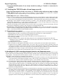
Communication phone cable with 4 pin
RJ14 connector at each end. See
connector detail lower right of this page.
yellow on the right
Sig
G2
+
G1
_
12 or 24V battery
system
=WATTS
Operating and programming instructions at
www.bogartengineering.com/ins
SOLAR
temperature
sensor
or
REPLACED PERCENTAGE FROM LAST DISCHARGE
To System Loads
minus (and ground)
1 A fast
blow fuse
+
=AMPS
shunt
To System
Loads +
yellow
green
red
black
4 sense and power
wires between
TriMetric TM-2030
and battery shunt
yellow on the left
yellow
green
red
black
Rj14 connectors on
each end of 4 wire
phone cable.
up to 100 ft or more
commonly available
phone cable
Crossed connection communication cable from TM-2030
to Charge Controller: Hold two connectors in the same
orientation next to each other. Note opposite color order
left to right
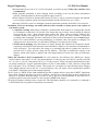
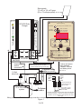
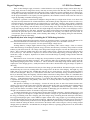
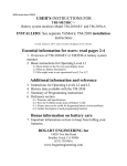
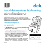
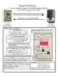
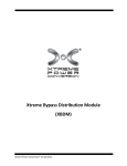
Wiring for TriMetric TM2030 and charge controller--not showing circuit breakers to battery or solar panels
Figure 1
3 of 16
Bogart Engineering
SC-2030 User Manual
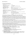
2. Technical Specifications:
Regulation type...........................................PWM
Solar panel open-circuit voltage..................55V maximum
Solar panel nominal voltage.......................12V - 24V, matched to the battery voltage
Nominal Battery voltage............................12V - 24V
Required operational current.....................While sun shining: 25mA. Solar dark: 1mA max
Maximum Battery voltage............. ...........35V
Battery type...............................................AGM, Gel, or flooded lead-acid
Solar-panel peak current...........................Max 31A for full efficiency. May be safely used with panels up to 60A,
however charging current will be reduced to protect charger.
MINIMUM in/out power efficiency at 30A: ...97.5% (12V systems) 98.5% (24 V systems)
MINIMUM in/out power efficiency at 15A: ...99%
Battery capacity.........................................10 to 10,000 amp hours
Terminal block wire gauge.....................Up to 6 AWG. (Larger stranded cables you can remove some strands to fit)
Charging profiles.....................................Three stages and optional fourth stage
Ambient temperature................................0 ºF to +140 ºF (−18 ºC to +60 ºC)
Dimensions.............................................. in.: 3 width X 4 1/4 length X 2 3/4 depth; cm: 7.6 width X 10.8 length
X 7 depth
3. General Solar Charging system suggestions and considerations
Balancing batteries with solar: If you intend to charge your batteries mainly or only by solar panels, it's
recommended by many battery companies to properly balance the battery storage capacity with adequate solar.
Too much battery for solar energy provided can result in undercharging that can reduce battery performance and
life. Peak solar panel currents of from 1/10 to 1/4 of the battery "C/20" ampere hour value are often recommended.
For example, solar panels that deliver up to 24 Amps could be optimally paired with a battery of 100 to 240 amphour capacity system. Otherwise you might want to provide an additional source such as generator or grid tied
charger to insure that your batteries frequently get a full charge.
Solar as excellent adjunct to generator charging: A generator can put a lot of energy into the batteries in a
relatively short time when they are not too close to being fully charged. As they become more fully charged,
batteries gradually accept energy at a lower rate—So charging them to full requires more hours than is usually
desirable to run a generator. Even if you don’t plan to use only solar for charging, solar panels are well suited to
deliver the last 20% of charge—which would otherwise require long generator times running inefficiently at a low
charging rate. This will enhance your battery life and reduce generator wear.
You can use other chargers along with this one: If other chargers are also used with your system, they can be
compatible with this system. It is important that the charging current from these shows on the TM-2030 amps
display— (see section 4.1.5 below) then the system will properly account for the charging of these others. If you
have another solar controller it should have a separate set of panels from which it is charging—you should not
attempt to have the same set of panels go to two different controllers.
4. Installation of the SC-2030: Explained in five sections:
4.1 Planning the installation
4.2 Verifying that TM-2030 reads volts and amps correctly
4.3 Tools and hardware required
4.4 Installing SC-2030 and connecting solar panels, Batteries, Temperature sensor
4.5 Verifying operation and installing correct charging profiles
4.1. Planning the installation
Installation must be performed by a person knowledgeable of proper electrical wiring, best
practices, safety and applicable electrical codes. If you do not meet these qualifications, please
ask someone qualified to perform, supervise, or inspect the installation.
4 of 16
Bogart Engineering
SC-2030 User Manual
4.1.1 Normal configuration—Paired with a TM-2030 For best performance, the SC-2030 should be paired
with a TM-2030 (TriMetric) monitor. The charge controller and the monitor are connected together using a low-cost
telephone wire, which can be over 100 ft. long.
4.1.2 Minimal configuration—Standalone. Without the TM-2030, the SC-2030 Solar Charge Controller can
perform only basic charge regulation. There are two jumper selected parameters located on the SC-2030 that are then
used to regulate the charging: The system voltage can be set to 12 or 24V. The battery type can be designated "AGM" or
"liquid electrolyte." These determine the charging only when the TM-2030 is not connected—otherwise they are
ignored. In this case, there is an "absorb" stage set to 14.6 or 29.2 volts (for 12 or 24V liquid electrolyte systems) or
14.3 or 28.6 (for AGM systems) which runs for two hours, followed by a float stage of 13.2 or 26.4 volts.
4.1.3 Temperature Compensation: The optional temperature sensor is recommended especially when using AGM
or Gel batteries, unless the batteries are kept at a fairly constant ambient temperature.
4.1.4 Review wiring diagram on page 3.
4.1.5 Can more than one charge controller be used?: If the TM-2030 and SC-2030 are connected together,
other charge controllers may be added for additional charging current, while still retaining most of the benefits gained
by using this paired system. They must be connected so the TM-2030 "sees" this current when they are charging. Also,
though all chargers go to the same battery set, the solar panels should be segregated into groups—with each group being
controlled by only one charger.
4.1.5 Locating TM-2030 monitor and SC-2030 charger. The TM-2030 is usually placed somewhere with
access in the living area to allow easy viewing and control of the SC-2030. Four small wires usually 22 or 24 gauge
connect the TM-2030 to the batteries and required shunt. In addition a four wire telephone cable will need to be
installed that sends control information from TM-2030 to SC-2030. These wires can be at least 100 feet long (30
meters). The SC-2030 will usually be located in the wire path from panels to batteries to minimize wire length from
panels to batteries. Unless the SC-2030 will be used without the TM-2030, it is not required that the SC-2030 be located
right near the batteries.
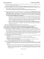
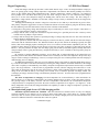
TABLE 1: Required minimum copper wire size for 3% loss.
One way total length from solar panels to SC-2030 plus SC-2030 to batteries
Length for 12V systems: For 24V systems double all distances
Maximum amps from
5 Amps
panels→
10 Amps
15 Amps
20 Amps
25 Amps
30 Amps
Wire
gauge
(AWG)
Diameter
(mm)
(ft)
(m)
(ft)
(m) (ft)
(m) (ft)
(m) (ft)
(m) (ft)
(m)
2*
6.544
230
70
115
35
76
23
57
17
46
14
38
11
4
5.189
144
44
72
22
48
14
36
11
28
8
24
7
6
4.115
91
27
45
13
30
9
22
6
18
5
15
4
8
3.264
57
17
28
8
19
5
14
4
11
3
9
2
10
2.588
36
10
18
5
12
3
9
2
7
2
**
12
2.053
22
6
11
3
7
2
**
**
**
*This wire gauge exceeds the terminal block’s maximum wire size and requires adapting.
** Not recommended
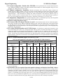
4.1.6 Determine wire size required from solar panels to charger and batteries from Table 1 above.
Wire size from solar panels to SC-2030 and from SC-2030 to batteries must be much larger for low voltage systems
compared to 120V house wiring to minimize power loss. The required size depends on (1) total maximum amps to be
delivered by the panels, (2) the system volts (12 or 24), and (3) the wire length. The recommended maximum lengths
assume a 3% maximum power loss using copper wire in a 12V system. Doubling lengths will increase loss to 6%.
However for 24V system double all lengths for 3% loss. All wiring must meet applicable electrical code requirements
with respect to maximum current versus gauge. With less than 3% power loss, this is normally not a problem.
5 of 16
Bogart Engineering
SC-2030 User Manual
4.1.7 Install TM-2030 monitor if not already installed according to "Installer's instructions for
TM-2030"
4.2. Verifying that TM-2030 reads volts and amps correctly
Proper charging depends critically on accuracy of TM-2030 voltage and current (amps) readings.
Check volts: For accurate battery-voltage control, the TriMetric’s voltage-measurement wire (called “B1” in TriMetric
wiring diagram) must be connected directly, or close to the battery’s positive terminal.
Check amps on the AMPS TriMetric display:
●Under zero-current conditions when all loads and charging sources are off, the TriMetric’s ampere indicator must show
0.0A, or ±0.1A at most when using the standard 500A/50mV shunt. When using the less common 100A/100mV shunt,
the zero-current value should be between minus 0.02-0.04A —which represents the current drawn by the TriMetric.
●The discharge current should be measured reasonably. For instance, a 12V, 12W light bulb connected to a 12V battery
should display approximately −1A. This assumes no charging is going on, since the amps display shows charge minus
discharge. The formula for Amps =Watts÷System Volts (12V or 24V).
●Verify that ALL charging sources should be shown as positive amps on the TriMetric TM-2030 when charging. All loads
on the batteries should show as negative values when they are operating. Related to this:
●The following is worth checking, because this mistake is so common: Check to make sure that nothing except battery
negative (no loads or charging sources or grounds) is connected to the battery negative side of the shunt—as illustrated in
figure 1 of the TM-2030 INSTALLATION INSTRUCTIONS.
4.3 Tools and hardware required
●Drill with bits of suitable sizes for entry of telephone cable and/or Temperature sensor into SC-2030 plastic enclosure
●Medium Phillips screwdriver for the large green terminal blocks connecting wire to panels and batteries.
●Small Phillips screwdriver for four screws holding front plate enclosure
●Wire cutters, wire strippers, and a lug crimper for the battery wire, the solar panel wire, etc.
●SC-2030 charge controller
●TM-2030 (TriMetric) battery monitor with sensing and power wires (assuming the TM-2030 will be connected)
●If TM-2030 is not yet installed, it will require an electrical shunt: 500A/50mV or 100A/100mV size. see TM-2030
installation instructions.
●Mounting hardware for the above, if required
●Wire of suitable size and length (as determined in section 4.1.6) from panels to SC-2030 and SC-2030 to batteries
● Common four wire conductor “telephone cable” up to 100 ft. long—to go from SC-2030 to TM-2030. This is the
common 4 wire telephone extension cable with RJ11 connectors sold in different lengths at hardware or other stores in
the telephone accessories section. The wiring must be crossed between the two connectors, as shown in the lower
right-hand corner of Figure 1 on page 3. This is usually the way they are manufactured—but check.
●Temperature sensor (optional but recommended unless batteries will remain at same temperature)
4.4 Installing the SC-2030, connecting solar panels, batteries, and Temperature sensor
Plan to mount the SC-2030 in a well-ventilated and shaded area to prevent overheating, and protected from direct rainfall.
The heat sink can get hot during charging; therefore the charge controller must be installed beyond the reach of animals and
young children. The black heat sink fins should be vertical—not horizontal, which means the printing of "SOLAR" or
"BATTERY" will be right side up or upside down (not sideways).
4.4.1 Run wires (size determined as described section 4.1.6) from solar panels to location for SC-2030, and from batteries
to SC-2030 location with enough extra length to easily connect to large green terminal blocks. Carefully mark on the
ends of the wire which are positive and which are negative—both to batteries and to solar panels.
4.4.2 If communication (phone) cable has RJ14 connectors attached at both ends, check that connectors are "crossed" as
shown in figure 1. Run phone cable from TM-2030 to SC-2030 location with sufficient length. If you have a RJ14
crimp tool and correct RJ14 connector, to avoid drilling a larger hole you could pass wire through a small drilled hole
through TM-2030 enclosure then use crimp tool to install connector (carefully observing polarity Fig 1). Don't yet
connect the communication cable to the TM-2030 (unless connectors at each end are attached and you don't intend to
put them on or change them later.)
4.4.3 Remove front panel and circuit board from SC-2030 enclosure by removing 4 screws and put it aside. Drill one or
more holes in the SC-2030 enclosure to allow the communication cable and the temperature sensor wire (if used) to
pass through in a location suitable to the positioning of the controller, wires and the rest of the system. The
temperature sense connector requires a 5/16 diameter hole to pass through. For the communication cable, as described
in 4.4.2 you could pass the wire through the hole and attach the connector similarly to 4.4.2 if you have the
appropriate connector and crimping tool. Reminder: be sure the connectors are attached "crossed" as shown figure 1.
6 of 16
Bogart Engineering
SC-2030 User Manual
4.4.4 Mount the enclosure on vertical surface so the heat sink fins go up and down. Use two screws on flanges, or you may
drill your own holes internally and use those.
4.4.5 Connect the temperature sensor connector (if used) and the communication cable to the two connectors on the back of
the SC-2030 (inside the box). Place the circuit board back onto the enclosure board and secure with four screws.
4.4.6 Place the temperature sensor (if used) near the batteries. The hole in the sensor could be connected to a battery
terminal—but this is not necessary for it to measure temperature.
For safety, turn off power from batteries and solar panels before doing next step
4.4.7 Connect the wires from batteries and the solar panel wires to the controller. For the following steps, refer to
wiring diagram, Figure 1 on page 3. For safety, turn all switches and circuit breakers off while
making the connections. While voltages in a 12V or 24V solar system are generally considered safe
from electrical shock, amperages can be very high and can create powerful arcs if accidentally
shorted, or when connections are made or unmade.
a. Connect the SC-2030 minus wire to the batteries. Observe in figure 1 (page 3) how the SHUNT is connected
to the batteries. The shunt has two large bolt terminals. One is connected to the battery negative terminal—
the other side is connected to the loads in your system. The wire from the SC-2030 “BATTERY minus”
terminal (large green) must go to the LOAD side of the shunt. Avoid a common mistake of connecting this
directly to the negative post of the battery. If you make this mistake the solar current will not register as
“amps” on your TM-2030, and charging will not be correctly controlled by the TM-2030.
b. Connect the wire from the battery + terminal to large green connector on the SC-2030 marked BATTERY +.
c. Connect two solar panel wires to the two large green terminals on the SC-2030 identified on the SC-2030 as
“SOLAR” . Be sure to observe correct polarity: + from panels to terminal marked SOLAR +, and minus to
terminal marked SOLAR “ —“.
4.4.8 Connect communication connector at TM-2030 end if not already connected.
4.4.9 Verify all wiring and polarities (plus and minus not reversed). Then close the switches or circuit breakers.
4.5 Verifying SC-2030 operation and programming charging parameters.
NOTE: References to “P” numbers such as P4, P16, etc. refer to user programmable values explained on page 12.
4.5.1 If the SC-2030 is connected to a TM-2030: You must do this when there is at least a little sun shining on the solar
panels (more than 0.5 amp of current). Check the green light on the SC-2030 Solar Charge Controller. If the two units
are communicating it should be on most of the time—but possibly occasionally blink off. If the green LED is off or
mostly off, except for occasional blinks on, check the communication cable again, check that the TriMetric is powered
and operating properly, and also verify that the phone cable contacts are crossed as shown in the lower right-hand
corner of Figure 1. Also, there must be at least a small amount of solar current coming from the solar panels.
4.5.2 If the SC-2030 is operating without the TriMetric:
If at least a little solar energy is coming in, the green LED will be usually off—but will occasionally blink on to indicate
the following:
●Flashing once, the charger is in the first charging state — first stage or “bulk” charging.
●Flashing twice, the set voltage has been reached, but the charger has not switched to floating mode yet.
●Flashing three times indicates floating mode.
●The amber LED indicates a normal charging state when it is ON. When flashing every half second, it is in over
current protection and charger is limiting current to a safe value for charging.
4.5.3 Last step: Programming the SC-2030 for your battery system when TM-2030 is connected.
Easy way: Most people will choose the easy way to enter this data. This method automatically enters 8 charging
parameters to control the charging, and also provides proper monitoring in most cases. This requires the following
two steps:
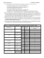
STEP 1.Find the "charging profile number" from the table below depending on the type of batteries and system
voltage you have, 12 or 24 volts. Our web site will (eventually!) have an expanded table if your batteries are not
listed here. If yours is not on the chart, and you have liquid electrolyte batteries (with caps on top for watering)
you could start with "Generic" profile 1 or 2 . If you have AGM batteries, start with profile 9 or 10. (See
"Concorde" on chart)
continued next page
7 of 16
Bogart Engineering
SC-2030 User Manual
After determining profile number, use Program P22 (of the TM2030) to enter data as described (in detail) here.
a. Press "SELECT" and hold it down until "P1" appears in display. Release.
b. Press SELECT repeatedly to get to "P7" (to select operational level).
c. Press SELECT and RESET together, momentarily, to get 3 lights to flash.
d. Use RESET to change display until operational level "L3" shows.
e. Press SELECT repeatedly to get to program "P22".
f. Press SELECT and RESET together, momentarily to get 3 lights to flash.
g. Use RESET to enter profile number from table 2 below into display.
h. Press SELECT once, to get out of program mode—but remaining in P22 with profile number showing.
I. Hold RESET down—watch as number go 5,4,3,2,1,0. Profile not entered until numbers stop changing
STEP 2. Determine the battery system capacity, in amp hours. To determine the system capacity you need to know the
capacity of each battery in amp hours—then multiply by the number of series strings in your system. The 20 hour value
specified for capacity would be appropriate. The default value automatically entered by step 1 is for 220 amp hours. If
your system capacity is not between 200-240 amp hours, change that value by entering the correct value into
program P3 in the TM-2030. Always do this after step 1 or this data will get overwritten.
STEP 3: In many RV’s or other installations, while charging, the voltage to items connected to the battery may exceed the
maximum safe limit under cold conditions. Although this may not provide ideal battery care, you may adjust P8 to
the maximum allowed charging voltage. This will override any other programmed settings. Early units do not have
this option. Call Bogart Engineering for upgrade.
For experts that want to customize the charging: Enter a profile number that is close to what you want. (see Table 4,
below on page 16). This overwrites all values. Then you may individually modify any of the eight parameters according
to your liking. Section 6.3, below, describes the function of each of these eight parameters.
TABLE 2: Find P22 profile number for your battery type and system voltage
Models
System
capacity
12
220
1
24
220
2
12
220
9
24
220
10
12
220
5
24
220
6
12
220
11
24
220
12
12
220
15
24
220
16
All wet cell.
Example: GC2
types
12
220
13
24
220
14
All liquid 6 V types
ExampleT-105
12
220
3
24
220
4
All liquid 6V
types:
example T-105
Wet Cell Generic
12
220
7
24
220
8
12
220
17
AGM Generic
12
220
18
"Generic" wet cell batteries
Concorde
Crown
Deka
GNB /Excide
Interstate
Trojan
US Battery
Generic 12V without higher volt
finish charge (see page 14)
Profile number. Enter in
P22 (Table 4, p16, has profile
System
Voltage
Manufacturer
Lifeline AGM
Sun-Xtender AGM
All wet cell
Monobloc example
8C11
Absolyte AGM
8 of 16
definitions)
Bogart Engineering
SC-2030 User Manual
5. Useful Information for everyday users
5.1 The best place to find information about the SC-2030 and TM-2030 system
is the "Quick Reference Guide to TM-2030 and SC-2030" included with the SC-2030. It has brief descriptions of all
functions and also has references to this SC-2030 User Manual and the TM-2030 User's and TM-2030 Installation
manuals for greater detail. These manuals will be occasionally updated and posted on our web site as we receive
questions from customers that we think haven't been adequately covered in those documents. We always welcome
comments for improvements.
5.2 A useful display item for seeing if your batteries are being properly charged
If you partially drain your batteries on a daily basis, we suggest understanding the new display function on the TM-2030
called "Replaced Percentage from Last Discharge" This is listed as a secondary display shown near the bottom of the
TM-2030 front panel, identified as “rPC”. This will be of lesser significance when your batteries are charged and
on “float” most of the time—when this may go to high values. Many battery companies recommend that when
recharging your batteries that you completely replace the amount of charge most recently discharged by your batteries,
plus add an additional percentage. This depth of discharge is recorded by the TM-2030 during the previous discharge.
For "wet cell" lead acid batteries it is often recommended that 106-115% be replaced. For AGM type (sealed) batteries
104-108% is often suggested. At the end of a day of solar charging, the “rPC” (“replaced percentage”) display will tell
you how much you have replaced. This level of charge may not happen every day—however if less than the ideal is
achieved for a day or two, it would be good to go even higher on subsequent days if possible. (Soon after you start
discharging your batteries again this will read 0%—to anticipate the next day's recharge.)
New with Version 2.2 of the TM-2030 monitor With this version, it is possible when viewing “rPC” function, to push
and hold the RESET button to momentarily observe the previous depth of discharge in amp hours upon which the rPC
percentage is based. This is useful, because if this discharge was small compared with your battery capacity, a large
value of rPC should be of much less, if any concern.
5.3 A useful display item to see if you have extra solar power in the afternoon
When charging with solar, often in the afternoon the batteries will begin to accept less solar energy—and as a result this
energy may be wasted although it could be used for some extra loads, such as a dishwasher or vacuum. With the TM2030 connected, there is a “secondary display” item that is not shown on the front panel called “UPr” (Unused power)
which displays this. If most of the solar power is now surplus (because the batteries are getting well charged), "YES"
will show on the display. If a lesser amount, the display will indicate the approximate number of watts that are being
wasted. Refer to the Quick Reference Guide, section 2.1 Also listed there is information about observing solar amps
(“SOL”) and battery temperature (ºC).
5.4 For information about the meaning of the LED lights on the SC-2030 charger
Refer to section 4 of the "Quick Reference Guide" referred to above. Section 6 in this SC-2030 User's Manual
describes in detail the meaning of the various charging modes referred to there.
5.5 There are two different standards you can select to define a “full charge.”
The highest (more stringent) standard is selected by using TM-2030 program P7 to choose L4 instead of L1, L2, or L3
which use a lower standard, which requires only that the battery voltage exceed the value in P1, and that the charging
amps be less than P2. The L4 level requires that in addition either the required "absorb time" or "percent overcharge"
be achieved, such that the "float" state has been reached. This establishes a better, but more difficult, level to reach.
Refer to the TM-2030 User's Instructions, section 6.2 for details.
5.6 Using History Data to diagnose system problems
The TM-2030 (TriMetric) makes history data available when the user level P7 has been set to “L2,” “L3,” or “L4” in
programming code “P7.” History is recorded daily for the past five days or the last five charge cycles, depending on the
parameter. This data can be used to diagnose some system problems. Please refer to the TM-2030 User’s Instructions,
section 6.3 for instructions on interpreting this data.
6. Technical information for interested and advanced users
6.1 Charging lead acid batteries—basic information
Charging a battery is very different than loading a tank with gasoline. First, when filling a tank it is very clear when
the tank is full, and trying to overfill simply results in gasoline being spilled without any damage to the tank. Second,
using up the gasoline until the tank is completely empty may be inconvenient, but again that does not damage the tank,
even if the tank remains empty for a long time. Thirdly, filling the tank slowly or fast, whether the weather is hot or cold,
or whether one is starting from a nearly-empty or nearly-full tank, does not affect the eventual amount of gasoline in the
tank. Finally, a fuel tank’s capacity does not vary over time.
9 of 16
Bogart Engineering
SC-2030 User Manual
None of these analogies apply to batteries. Lead-acid batteries can accept higher charge currents when they are
nearly empty, but must be charged more slowly when they are nearly full because then they will not readily accept the
charge. Batteries need to be frequently fully charged. If a battery is allowed to operate consistently at a low charge level,
its capacity to hold charge decreases over time. This means that a battery needs to be fully charged every now and then
for the proper maintenance of its capacity. In solar applications, this sometimes cannot be achieved in the course of a
single day, depending on sunshine and energy usage.
Sometimes a generator is used instead of sunlight to charge the battery at a high current for one or two hours each
day. This can easily shorten the life of lead-acid batteries, which cannot get fully charged in two hours even with a very
powerful generator. If only charged with very high currents over a short time, a battery’s charge capacity will decline
over time. A “hybrid” generator-solar system would be preferable with a strategy of using the generator to provide a fast
charge early in the morning, when the battery is at its lowest charge level, and stop when the battery can no longer
accept high charging currents. By the time the sun is high enough, the solar panel can take over the charging at a lower
current for the following six to nine hours. Alternatively, a surplus of solar panels can accomplish something similar, but
that means the peak solar power in the afternoon, when batteries are accepting less current, may not be used. To
overcome this, plan to use heavier loads, such as laundry, dish washing or well pumping, during the mid afternoon,
when batteries accept less solar energy.
6.2 Specifically how solar chargers, including the SC-2030 charge batteries
The following charging description applies when the SC-2030 Solar charger is connected with the TM-2030. If for
some reason the TM-2030 is not connected, it uses a basic charging procedure, to be described in section 6.3.
This discussion refers to 12V systems—for 24V systems multiply voltages by two.
To charge batteries, a charger supplies electrical energy to the battery with a certain "voltage." "Volts" is a measure
of how hard the charger is attempting to push the energy (electrons) into the battery. The battery always tends to resist the
tendency to push the electrons in—the voltage of the charger must be high enough to overcome the resisting force of the
battery. This is a little like pushing water into a pipe which is under pressure—enough force must be provided to push it
in or it will not go. The "current" or "amperes" is a measure of how much (charge) energy is actually flowing in. The
actual flow (“amps” or amperes) depends on two factors: how hard the charger is pushing (voltage) and how much the
battery is resisting.
When batteries are at a lower state of charge they do not push back very hard, and the battery will easily absorb all
the charge (amperes) that the charger can supply. This is called the "bulk" stage of charging, and the "voltage" from the
charger during charging will be below 14 volts or so. This is when most of the charge can go into the battery, and is the
simplest part of the charging process; usually the batteries will be able to absorb all the energy the charger is capable of
delivering.
When the batteries reach about 85% full, the job of the charger gets more difficult. The batteries begin to resist more,
and absorb amps at a lower rate, meaning that it takes a longer time to do the rest of the charging. One might say, "why
bother, then to go beyond 85% full? Wouldn't this make the job easy on the charger? Just always operate the batteries
from 55%-85% charged." Well, yes it would, but the reason this is not a satisfactory strategy for lead acid batteries is
that if you don't fully charge them regularly, it makes it harder in the future to charge them as much. It is remarkable how
often even authoritative sources on lead acid battery charging repeat the phrase that "lead acid batteries do not have
memory." Lead acid batteries DO have a memory—if you do not fully charge them, they will remember that, and if this
is repeated often their capacity will gradually "walk down" as is correctly described in charging information from the
Concorde battery company.
This presents a challenge to solar charging— because the solar day starts to end as the batteries become more
resistant. This can result in a battery that is not fully charged when the day ends. It is frequently observed that batteries
being charged only by solar tend to lose capacity to hold energy— described as batteries becoming “sulfated”. This
conveys the fact that the lead sulfate, which is the byproduct of discharging gets more difficult to convert back to fully
charged lead and sulfuric acid if it sits around too long before recharging.
To continue the charging story, once the batteries become more resistant to charging—when the charger rises to 14.4
volts, (at 77 degrees F or 25 degrees C) liquid electrolyte batteries will begin to "gas" which means that although part of
the energy is still doing some slower charging, part of the charger energy is breaking down the electrolyte in the battery
into oxygen and hydrogen gases—and in addition a higher amount of the energy begins to go into heating the battery
instead of the desirable conversion of the chemical charging. Although the gassing does waste some energy, this turns out
to be desirable in liquid electrolyte batteries because the gas bubbles stir up the electrolyte which otherwise can stratify—
because without the stirring the heavier acid can sink to the bottom while weaker acid goes to the top causing unequal
charging at the top and bottom. In AGM batteries, the design is different, so gassing typically doesn't occur, which makes
them a little more efficient.
10 of 16
Bogart Engineering
SC-2030 User Manual
Good solar chargers will then go into what is often called "absorb" stage—where the charger holds the voltage just
above the gassing point (voltage ideally temperature compensated). The batteries then absorb gradually less and less
energy as they further charge. Most manufactured solar chargers maintain the "absorb" voltage for a set amount of
time—perhaps one to four hours before they go into the "float" voltage of about 13.2 volts. Often the better chargers
allow you to set the exact absorption voltage, the holding time, and the exact float voltage. The float voltage is a
maintenance voltage which is intended to be the ideal voltage to keep a battery at minimum wear for the longest time
once it's fully charged.
Although just maintaining the "absorb" voltage for a fixed time is not a bad way to decide when to go into "float",
many battery companies suggest that it is better to monitor the amount of current (amperes) going into the battery during
this time and then go into float based on this. There are three variations on this method:
(1) Charge above the gassing voltage until the amperes drop to a sufficiently low value, say an "ampere" value that is 1%
or 0.5% of the amp hour "capacity" of the batteries.
(2) Charge until the value of amps into the batteries stops decreasing for a specified period of time—and stays at this
constant value for perhaps a couple of hours.
(3) Charge until the charger has replaced a specified percentage of charge amp hours that was last removed from the
batteries during its last discharge cycle.
These options are unusual with most solar chargers, but the first or third is possible with the SC-2030 solar charger
when used with the TM-2030 monitor. The TM-2030 measures the previous amount of discharge (typically the night
before), then when recharging requires returning 105-115% (or even more) of that amount, adjustable by the user. The
problem for many chargers is that they do not measure or know the exact value of amperes or amp hours going into the
batteries. They may measure the amps from the charger going into the battery and loads together, but they don't know
what percentage of this is going into the battery compared to the loads, so these methods of observing battery amps are
not available.
By returning a constant additional percentage, excess charge that is returned depends on the amount that was
previously removed. This has the effect that the "absorb" time is not always the same, but is adjusted to the previous day's
usage to avoid overcharge or undercharge—however, as said previously, the more common problem with solar charging is
under charging, not over charging.
An additional method the SC-2030 uses to get in sufficient charge is that it has an (optional) finish charge stage to
try to increase the intake of current into the battery by boosting the voltage when the current has declined to a safe enough
value. This is explicitly recommended by some battery companies for liquid electrolyte batteries and recently even AGM
types—but not gel batteries.). If the SC-2030 is programmed to do this, after the charging current decreases to a safe
value while in "absorption" state the SC-2030 then increases voltage (while regulating current) to attempt to put more
charge at the end when the battery is becoming extra resistant so as to attain the specified overcharge amount. The
overcharge percentage, maximum voltage, and maximum permitted current are all values that can be programmed into
the TM-2030.
The effect of temperature on charging: The ideal temperature for a lead acid battery is often considered to be
about 25 degrees C (77 degrees F). When batteries are cold, the charging process is slower, so they take longer to charge.
The gassing voltage of the battery increases with lower temperature—and therefore the recommended "absorption"
voltage should rise as temperature goes below the usual reference temperature of 25 degrees C (77 degrees F). If the
battery temperature varies much, the charger should have the capability to adjust its voltage to temperature, especially for
sealed AGM or gel types.
6.3 Description and graph of exact SC-2030 charging profiles
Standalone operation-without the TM-2030: With the TM-2030 not connected, there are only two charging
selections available (by two jumpers you set on the SC-2030 circuit board.) They allow choice for "AGM or liquid
electrolyte" and "12 or 24V" system. These are intended to be for "backup" charging if for any reason the TM-2030 is not
connected. When the TM-2030 is connected, these values are ignored.
Continued next page
11 of 16
Bogart Engineering
SC-2030 User Manual
The chart below shows the voltages used depending on how the jumpers have been set. It begins charging at
maximum solar current until it reaches the limiting "absorb" voltage shown. After that it charges for an absorb time of
two hours. Then it regulates at the float voltage shown.
Table 3: Shows “absorb volts” and “float volts” for jumper settings –TM-2030 not connected
SC-2030
Battery type jumper
setting
System
Voltage
jumper setting
Absorb voltage (temperature
compensated to 25º C if sensor is
connected)
Float voltage
(after 2 hours at
Absorb)
Liquid electrolyte
12V
14.7V
13.2V
Gel or AGM
12V
14.2V
13.2V
Liquid electrolyte
24V
29V
26.4V
Gel or AGM
24V
28.4V
26.4V
6.4 Two Graphs of charging profiles for SC-2030 when TM-2030 is connected
The first profile (page 14, figure 2) is more typical of most good solar chargers. However the SC-2030 has an additional
unusual option of setting a "percentage of overcharge" value compared to last discharge from 100 to 120%.
The second profile (page 15, figure 3) adds a higher voltage "finishing absorb," current limited charging stage, to safely
more fully charge batteries as they become more resistant to charging, originally intended for lead acid liquid
electrolyte (wet cell) types—but now some companies are recommending this for AGM batteries too .
Each profile shows the program values that you use with the TM-2030 to adjust the charging; these are identified by the
"P1, P2, etc which identify values that you enter using theTM-2030.
Important note about settings for P2 and P21. These are percent settings that refer to the percentage of the value
programmed into P3. For example, for P2 the "amps" set point equals the value in P2 (in percent) times the P3 value.
Similarly, P21 (max Amps finish value) is also referenced as a percent of the P3 setting.
The P8 “high voltage limit” setting is not installed by the install profile. Some systems (often in RV’s) don’t allow
battery voltage as high as typically recommended for properly charging batteries. If you must impose a maximum
voltage limit, use program P8 to set voltage from exceeding this value, even during low temperature--although this
could compromise ideal charging. To disable, place it to a voltage that your system will never reach, such as 65.0V.
The P22 "battery install profile" setting automatically writes 8 values shown below (EXCEPT P8) as shown in Table
4 below. Always enter P22 first. After that any other values may be changed individually if desired. If you find a
profile set that has most of the values you want, first enter that profile, then change the ones that you want to be
different. Presently there are 18 profiles available. We may add more in the future in later revisions of the TM-2030.
If you wish to use a “conventional” type charge profile, typical of most controllers manufactured today, this may be
easily accomplished by setting program P21 to “OFF”, as described near the top of page 14. Or use profiles 17 or 18
when entering a charging profile in P22.. All of the profiles, except P17 and P18 have an extra “higher voltage finish
charge” to give a more thorough charge, which is recommended by many battery companies, including some
manufacturers of AGM type batteries.
P1: Absorb volts: When charging begins, the maximum solar current is sent to the batteries until this voltage is
reached. Then the charger limits voltage to this value. (10.0-65.0)
P2: Charged setpoint. The “amps charged setpoint” is equal to P2, expressed as a percentage from 0.0-10.0%, times
P3 (battery capacity). When battery voltage is equal or greater than P1,(when the TM-2030 is in Levels 1-3) and
the amps drops to P2 times P3, the batteries are signaled as "charged." (In Level 4, the standard is much higher:
batteries must go into float mode before they are signaled as “charged”.)
P3: Total battery system capacity (in amp hours). (10-10,000 amp hours)
P8: Absolute max permitted charging voltage: Default=65.0. Adjust this (if necessary) to limit the maximum
charging voltage allowed, for example if temperature compensation raises voltage in cold conditions beyond what
is permissible for other devices connected to the battery that can’t tolerate the voltage that would otherwise be
desirable for proper battery charging. Note that P15 is the battery limit. P8 can prevent P15 from being reached.
P14: Limit timer for charging, before going into "Float" described in the profile graphs. (0.0-25.0 hours)
P15: Finish charge (high) voltage limit—allowed only after the amps drop below the P21 current limit. (10.0-65.0)
P16: Float voltage (10.0-65.0)
P20: Percent of overcharge before going into "float" (0-20%).
P21: Finish charge Amps limit (expressed as a percentage of P3) below which amps must be to rise above P1 voltage
12 of 16
Bogart Engineering
SC-2030 User Manual
to P15 voltage.
P22: The "charge profile" entry program: simultaneously programs all of above eight values based on system voltage and the battery type selection. See Table 4, page 16 to see the eight values actually programmed for each
profile.
6.5. What determines when SC-2030 goes into float:
these are also shown in graphs on page 14 and 15.
For the “3 state” profile: Timer starts counting with P14 time when goes into “Absorb” state.
The first time after the charger is turned on. Goes into float when (Amps drops below P2*P3) OR (Timer expires.):
After the first time: {(Amps drops below P2*P3) AND (% overcharge>P20)} OR (Timer expires with P14 time.):
For the “4 state” profile: Timer starts counting with P14 time, as shown on 4 state charging profile, page 15.
The first time after the charger is turned on: Goes into float when (Amps drops below P2*P3) OR (Timer expires.):
After the first time: {(Amps drops below P2*P3 at least once during Absorb) AND (% overcharge>P20)} OR (Timer
expires with P14 time.):
6.6. Battery Equalization: how to initiate or terminate the process.
TM-2030 ver. 2.2 or higher. Call Bogart Engineering for upgrade. Equalization is a process of overcharging a battery that
in the past may have been undercharged. Undercharging can cause “sulfation” of the battery which will cause it to lose
some capacity to hold energy. Equalization is an overcharge that can help restore the damage done by under charging.
For example, you might want to do this if a reading with a hydrometer of the specific gravity of the battery electrolyte is
lower than what the battery manufacturer recommends.
The SC2030 (with TM-2030) allows you to manually equalize batteries as follows: 1. It will attempt to charge the
battery until it reaches the “Absorb” voltage that has been set in program P1. 2. It stays in “Absorb” until the charging
amps drop below 5% of the P3 (“amp hour”) programmed value. 3. It then switches to a “current regulate” stage that
limits the current (in amps) to a maximum value of 5% of the P3 programmed value while limiting the voltage to rise no
higher than the P15 value. It counts the total time for step 3, and when 2 hours have accumulated it goes into “float”. If
the P1, P3 or P15 values are not what you want, temporarily change them during equalization. For longer times, repeat
the process. IMPORTANT: If P8 is being used to limit battery voltage, it may nullify the benefit of equalization unless
you adjust it higher than the P15 value.
How to initiate or terminate the equalization process: 1. Use the SELECT button to observe the “Days Since Equalize”
display. This is one of the “Extra data” items shown at the bottom portion of the front panel label of the TM2030. The
display will show “dSE” (Days Since Equalized) alternating with a number of days. 2. Hold the RESET button down for
about 5 seconds to reset the Days to 0.0. If they are already 0.0, then this step need not be taken. 3. With 0.0 showing
in display, push RESET again for about 5 seconds—it will show “Equ”. This initiates the equalization described above.
If it is desired to terminate the process, use SELECT to again get to this display, which will be show “Equ” unless the
equalization step has ended Push the RESET button for 5 or so seconds and it will go to “0.0” thus terminating the
equalization. To lengthen the process, you may then restart at any time.
Warranty and customer service
Limited warranty
The SC-2030 Solar Charge Controller is warranted for four years against any manufacturing defect. Any controller not
meeting the specification or rated performance shall be replaced or repaired, at Bogart Engineering’s discretion, provided it
has not been subjected to abuse or misapplication. In many cases, if we know or believe a problem is due to a manufacturing
defect, we will extend this to 5 years or more. For warranty service, please contact us or your dealer before shipping your SC2030.
How to obtain customer service
Please contact your dealer, or contact Bogart Engineering, Inc. at 19020 Two Bar Road, Boulder Creek, CA 95006,
(831) 338-0616. Contact us or the dealer before returning any item.
www.bogartengineering.com
13 of 16
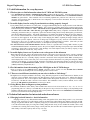
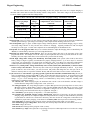
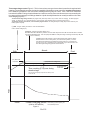
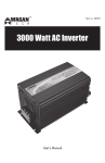
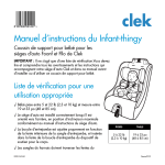
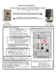
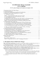
Three stage charge control: Figure 2. This is closer to how most good conventional controllers charge lead acid
batteries--except that this controller also has the capability (if desired) to return a specified number of amp hours
to the batteries (compared to the most recent discharge) before going into "float". Also, it has been considered
best suited for AGM or Gel type lead acid batteries--however recently some manufacturers are recommending the
four stage profile (next page) for AGM type batteries. Liquid electrolyte batteries can usually benefit from four state
solar charging (Figure3).
To select three stage charge control, set program P21 (finish amp value in %) to "OFF." Then for charging, set these program
values: P1, Bulk volts. P14, max absorb time. P16, float volts and optionally P20 (% overcharge amp hours.)
To properly monitor "percent full", also set these program values: P2: charged setpoint amps (amps =P2% times P3), P3:
battery system capacity.
(1) Bulk, charges battery at maximum rate until the batteries
reach "absorb voltage" (P1).
(2) Absorb, charges at constant voltage= (P1)
The FIRST time after TM-2030 is powered: runs until either amps<P2 value OR until P14 Max time is reached.
For all times AFTER the first: runs until (amps<P2 AND that P20 percentage overcharge is reached) OR (until
P14 Max time is reached.)
(3) Float, which holds charging to a lower float voltage (P16) until the voltage
declines below 12.4V for 12V systems (or 24.8V for 24V systems) or %Full
goes below 98% followed by available solar charge resource. This stage may
not occur every day in systems that are charged with only a solar resource, and
then discharged during daily periods of solar absence.
Absorb
Bulk
Volts
(P1) Bulk Volts
10-35Volts
(P20) percentage overcharge amp-hr
1-20% of previous day's amp hour discharge.
Float
(P14) Max over voltage time
allowed: 0.1-10.0 hours
Time counting (P14) runs during
absorb stage
(P16) Float Volts
10-35 volts
Amps
Time counting temporarily stops whenever battery Volts
is less than P1.
Hours
3 state charging profile
(AGM or Gel batteries)
Figure 2
14 of 16
Total battery system capacity P3
10-10,000 amp hours
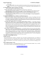
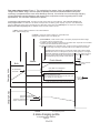
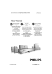
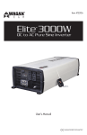
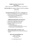
Four stage charge control: Figure 3. This method has four stages, having an additional final higher
voltage "finish absorb" stage, also with optional capability to deliver a measured additional amp hour
overcharge (compared with the most recent discharge amount). It is suited to do a more thorough charging
of liquid electrolyte lead acid batteries--and recently some companies are also suggesting this for AGM
type batteries. This can better maintain their capacity.
To select four stage charge control, program P21 (finish %amp value of P3) must NOT be "OFF." Then for charging, set
these program values: P1: Bulk volts. P2: Absorb end amps value. P3: Battery system capacity, amp-hours. P14: Max absorb
time. P15: Max finish charge volts, P16: Float volts. P21: Max finish charge amps and optionally P20: % Amp hours overcharge.
When these values are properly set, the TriMetric will also correctly measure "% Full"
(1) Bulk, charges battery at maximum rate until the batteries
reach "absorb voltage" (P1).
(2) Absorb, charges at constant voltage (P1). Terminates when
charging amps decline to (P2) % of capacity P3.
(2) Finish Absorb, limits current to (P21 % of capacity P3) amps but allows voltage
to continue to rise to up to (P15) volts.
The FIRST time after TM-2030 is powered up: terminates when amps has met V/A criteria
at least once OR until P14 Max time is reached.
For all times AFTER the first: terminates when (amps has met V/A criteria at least once
AND P20 percentage overcharge is reached) OR until (P14 Max time is reached).
(4) Float, which holds charging to a lower float voltage (P16) until the voltage
declines below 12.4V for 12V systems (24.8V for 24V systems) or % full goes
below 98% followed by available solar charge resource. This stage may rarely
occur in systems that are daily charged with only a solar resource, and then
discharged during daily periods of solar absence.
Finish Absorb
Absorb
Max finish volts P15
10-35 volts
Charging Volts
Bulk
Charging Amps
Float
(P14) Max over voltage time
allowed: 0.1-10.0 hours
(P1 )Bulk Volts
10-35Volts
Time counting (P14) starts here when P21 is not “off”.
Starts here when P21 is "off".
(Time counting temporarily stops whenever batt Volts is less
than P1. Resets to 0 when “charged.”
(P20) percentage overcharge amp-hr
1-20% of previous day's amp hour discharge.
(P21) Finish Amps value =
(P21) % of value in P3
"Charged " setpoint amps =
(P2)% of value in P3
Hours
Total battery system capacity P3
10-10,000 amp hours
4 state charging profile
for liquid electrolyte batteries
Figure 3
15 of 16
(P16) Float Volts
10-35 volts
Bogart Engineering
SC-2030 User Manual
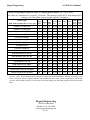
TABLE 4: Programmed values for each P22 charging profile number. See *NOTE below
All values are normalized to a “capacity” of 220Ahr. After placing a profile in P22, then change the P3
setting to your value unless your system has capacity=220 Amp hr.
Profile
P2
P1
Battery type
number
Absorb Amps
( with total system volts not battery volts) P22
V
setpt
P14
P15
P16
P20
P21
capacity Time
Ahr
hr
P3
high
V
float
V
Over
charge
Finish
amps
"Generic" wet cell (12V)
1
14.4V
2%
220AH
4h
15.7
13.2
10%
3%
"Generic" wet cell (24V)
2
28.8
2%
220AH
4h
31.4
26.4
10%
3%
Trojan wet cell (12V)
3
14.4V
2%
220AH
4h
16.2V 13.4
10%
3%
Trojan wet cell(24V)
4
28.8V
2%
220AH
4h
32.4V 26.8
10%
3%
Crown wet cell(12V)
5
14.5V
2%
220AH
4h
15.9
13.5
10%
3.5%
Crown wet cell(24V)
6
29.0 V
2%
220AH
4h
31.8
27.0
10%
3.5%
US Battery(12V)
7
14.8V
2%
220AH
4h
15.5
13.0
15%
3.5%
US Battery(24V)
8
29.6 V
2%
220AH
4h
31.0
26.0
15%
3.5%
Concorde AGM(12V)
9
14.3 V 2.0% 220AH
4h
16.5
13.3
7%
2%
Concorde AGM(24V)
10
28.6 V 2.0% 220AH
4h
33.0
26.6
7%
2%
Deka monobloc(12V) 8A, 8G
11
14.2 V
2%
220AH
8h
14.2
13.5
20%
5%
Deka monobloc (24V) 8A, 8G
12
28.4 V
2%
220AH
8h
28.4
27.0
20%
5%
Interstate(12V) wet cell
13
14.5 V
2%
220AH
4h
15.3
13.4
15%
4%
Interstate(24V) wet cell
14
29.0 V
2%
220AH
4h
30.6
26.8
15%
4%
GNB-Absolyte(12V) VRLA
15
14.3 V
1%
220AH
8h
14.3
13.5
7%
2%
GNB-Absolyte(24V) VRLA
16
28.6 V
1%
220AH
8h
28.6
27.0
7%
2%
Generic-Wet Cell-no hi volt finish
17
14.7
2%
220AH
4h
15.0
13.2
12%
0FF
Generic-AGM-no hi volt finish
18
14.3
2%
220AH
4h
15.0
13.3
7%
0FF
*NOTE: We occasionally update these profiles with what we consider better data, so your unit may not have
precisely what’s shown. Manufacturers sometimes change their recommendations. And not infrequently some
battery companies will have slightly different recommendations on the same web site, depending on which page
you look. After loading a profile you may want to check and change any individual program value shown on this
table.
Bogart Engineering
19020 Two Bar Road
Boulder Creek, CA 95006
www.bogartengineering.com
16 of 16