1
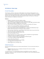
ACUVision
User Guide
Copyright
Copyright © 2005, GE Security Inc. All rights reserved.
This document may not be copied in whole or in part, or otherwise reproduced except as specifically permitted under
US copyright law, without the prior written consent from GE.
Document number/revision: 460936001B.
Disclaimer
The information in this document is subject to change without notice. GE, in keeping pace with technological
advances, is a company of product innovation. Therefore, it is difficult to ensure that all information provided is
entirely accurate and up-to-date. GE accepts no responsibility for inaccuracies or omissions and specifically
disclaims any liabilities, losses, or risks, personal or otherwise, incurred as a consequence, directly or indirectly, of the
use or application of any of the contents of this document.
This publication may contain examples of screen captures and reports used in daily operations. Examples may
include fictitious names of individuals and companies. Any similarity to names and addresses of actual businesses or
persons is entirely coincidental.
Trademarks and
patents
GE and the GE monogram are registered trademarks of General Electric.
ACUVision product and logo are registered trademarks of GE Security.
Other trade names used in this document may be trademarks or registered trademarks of the manufacturers or
vendors of the respective products.
Software license
agreement
GE software supplied with GE products is proprietary and furnished under license and can be used or copied only in
accordance with the license terms.
THE ENCLOSED PROGRAM IS FURNISHED SUBJECT TO THE TERMS AND CONDITIONS OF THIS AGREEMENT. RETENTION
OF THE PROGRAM FOR MORE THAN 30 DAYS, OPENING OF THE SEALED WRAPPER, IF ANY, SURROUNDING THE
PROGRAM, OR USE OF THE PROGRAM IN ANY MANNER WILL BE CONSIDERED ACCEPTANCE OF THE AGREEMENT
TERMS. IF THESE TERMS ARE NOT ACCEPTABLE, RETURN THE UNUSED PROGRAM AND ANY ACCOMPANYING DOCUMENTATION TO GE FOR A FULL REFUND OF THE LICENSE FEE PAID. (FOR INFORMATION REGARDING THE RETURN OF
PROGRAMS ENCODED OR INCORPORATED WITHIN EQUIPMENT, CONTACT THE NEAREST GE SALES OFFICE.)
Intended use
Use this product only for the purpose for which it was designed; refer to the data sheet and user documentation. For
the latest product information, contact your GE sales representative or visit us online at www.gesecurity.com.
FCC compliance
This equipment has been tested and found to comply with the limits for a Class A digital device, pursuant to part 15
of the FCC Rules. These limits are designed to provide reasonable protection against harmful interference when the
equipment is operated in a commercial environment. This equipment generates, uses, and can radiate radio
frequency energy and, if not installed and used in accordance with the instruction manual, may cause harmful interference to radio communications.
You are cautioned that any changes or modifications not expressly approved by the party responsible for compliance could void the user's authority to operate the equipment.
III
ACUVision Manual Revisions
Date
Notes
2 February, 2005
Initial Release of the ACUVision Manual
13 June, 2005
Introduction of ACUVision at the customer conference
IV
ACUVision
User Guide
Introduction
Safety Terms and Symbols
WARNING:
This symbol is intended to alert the user to the presence of uninsulated "dangerous voltage" within the
products enclosure that maybe of sufficient magnitude to constitute a risk of electric shock to persons.
CAUTION:
This symbol is intended to alert the user to the presence of important operating and maintenance (servicing)
instructions in the literature accompanying the product.
Introduction
For Your Safety
The following WARNINGS: and CAUTIONS: appear here for your safety. They are general in nature and do
not pertain to specific procedural steps. There are additional safety precautions that appear at the point in the
installation and/or maintenance procedures where a hazard is most likely to be encountered.
WARNING:
Be sure to observe battery manufacturer's instructions:
This warning applies to the Gel Cell batteries (PN ACU-BAT07)
Danger Explosive Gases
•
•
•
•
•
•
Can cause blindness or severe injury.
Use in a well-ventilated area away from open flame, cigarettes, sparks, and other sources of ignition.
Shield eyes and face when working around battery.
Do not make direct contact between the positive and negative terminals.
Do not puncture, disassemble or incinerate battery.
Dispose of in accordance with environmental regulations.
Poison - Contains lead compounds and corrosive acid
•
Contains sulfuric acid and can cause sever burns. In the event of contact flush with water and obtain
immediate medical attention.
Keep out of reach of Children
Charge in accordance with manufacturer’s instructions
WARNING:
The ACUVision components described in this manual contain electrical shock hazard potential. Only
qualified personnel should perform installation and maintenance. Use the appropriate procedures to
remove power before proceeding with servicing.
WARNING:
Make certain that the AC power source circuit breaker(s) is off BEFORE proceeding. Failure to heed this
WARNING can cause damage to unit(s).
DANGER:
Do not use the ACUVision Controller’s, Remote Reader Electronics (RRE), Remote Input Module (RIM) or
Remote Relay Module (RRM) to switch any voltage above 30 volts. Failure to heed this WARNING can
cause death, personal injury or damage to unit(s).
CAUTION:
Prior to handling ACUVision System components, be sure to follow the two rules below to avoid damaging
the Integrated Circuits by static electricity.
•
•
CAUTION:
Handle all static-sensitive components at a static safeguarded work area.
Transport all static-sensitive components in static-shield containers or packages.
The ACUVision controllers must have separate conduit run to each enclosure. Only cables/wires that begin
or terminate in the enclosure should run into the enclosure. DO NOT use the enclosure(s) as "pull-boxes" for
any foreign wiring. The enclosures should be arranged for separate conduit runs.
V
VI
ACUVision
User Guide
NOTICE: FIRE SAFETY NOTICE
WARNING:
NEVER connect any card reader devices or locks onto doors, gates or barriers that may be fire exits
without first consulting and getting approval of applicable local officials. Use of push buttons to exit
may be illegal. Single action exit may be required. Obtain proper permits and approvals in writing
before installation.
Introduction
Important Information
SERVICE STATEMENT
Control devices are combined to make a system. Each control device is mechanical in nature and all
mechanical components must be regularly serviced to optimize their operation. All GE Security and authorized
distributors offer Technical Support Programs that will ensure your continuous, trouble-free system
performance.
For further information, contact GE Security or your nearest GE Security representative.
Contact Us
Our Address
Correspondence should be sent to the following address:
GE Security
791 Park of Commerce Boulevard
Suite 100
Boca Raton, FL 33487
USA
Tech Support Telephone Numbers
Tel. -- 888.GESecurity (888) 437-3287
Electronic E-mail Address
Technical Support
[email protected]
Web Site
http://www.GESecurity.com/
VII
VIII
ACUVision
User Guide
Contents
Contents
Introduction . . . . . . . . . . . . . . . . . . . . . . . . . . . . . . . . . . . . . . . . . . . . . . . . . . . . . . . . . . . . . . . . . . . . . . . IV
Safety Terms and Symbols . . . . . . . . . . . . . . . . . . . . . . . . . . . . . . . . . . . . . . . . . . . . . . . . . . . . . . . . . . . . . . . . . . . . . . . . . . IV
For Your Safety. . . . . . . . . . . . . . . . . . . . . . . . . . . . . . . . . . . . . . . . . . . . . . . . . . . . . . . . . . . . . . . . . . . . . . . . . . . . . . . . . . V
NOTICE: FIRE SAFETY NOTICE . . . . . . . . . . . . . . . . . . . . . . . . . . . . . . . . . . . . . . . . . . . . . . . . . . . . . . . . . . . . . . . . . . . . . . . . VI
Important Information . . . . . . . . . . . . . . . . . . . . . . . . . . . . . . . . . . . . . . . . . . . . . . . . . . . . . . . . . . . . . . . . . . . . . . . . . .VII
SERVICE STATEMENT . . . . . . . . . . . . . . . . . . . . . . . . . . . . . . . . . . . . . . . . . . . . . . . . . . . . . . . . . . . . . . . . . . . . . . . . . . . . . . . VII
Contact Us . . . . . . . . . . . . . . . . . . . . . . . . . . . . . . . . . . . . . . . . . . . . . . . . . . . . . . . . . . . . . . . . . . . . . . . . . . . . . . . . . . . . . . . . VII
Our Address . . . . . . . . . . . . . . . . . . . . . . . . . . . . . . . . . . . . . . . . . . . . . . . . . . . . . . . . . . . . . . . . . . . . . . . . . . . . . . . . . . . . . . . VII
Tech Support Telephone Numbers . . . . . . . . . . . . . . . . . . . . . . . . . . . . . . . . . . . . . . . . . . . . . . . . . . . . . . . . . . . . . . . . . . VII
Electronic E-mail Address . . . . . . . . . . . . . . . . . . . . . . . . . . . . . . . . . . . . . . . . . . . . . . . . . . . . . . . . . . . . . . . . . . . . . . . . . . VII
Web Site. . . . . . . . . . . . . . . . . . . . . . . . . . . . . . . . . . . . . . . . . . . . . . . . . . . . . . . . . . . . . . . . . . . . . . . . . . . . . . . . . . . . . . . . . . . VII
Contents. . . . . . . . . . . . . . . . . . . . . . . . . . . . . . . . . . . . . . . . . . . . . . . . . . . . . . . . . . . . . . . . . . . . . . . . . . . IX
List of Figures . . . . . . . . . . . . . . . . . . . . . . . . . . . . . . . . . . . . . . . . . . . . . . . . . . . . . . . . . . . . . . . . . . . . . . XI
Chapter 1.
ACUVision Overview. . . . . . . . . . . . . . . . . . . . . . . . . . . . . . . . . . . . . . . . . . . . . . . . . . . . . 1
ACUVision Overview . . . . . . . . . . . . . . . . . . . . . . . . . . . . . . . . . . . . . . . . . . . . . . . . . . . . . . . . . . . . . . . . . . . . . . . . . . . . . 2
Product Description . . . . . . . . . . . . . . . . . . . . . . . . . . . . . . . . . . . . . . . . . . . . . . . . . . . . . . . . . . . . . . . . . . . . . . . . . . . . . . . . . .2
Default Passwords . . . . . . . . . . . . . . . . . . . . . . . . . . . . . . . . . . . . . . . . . . . . . . . . . . . . . . . . . . . . . . . . . . . . . . . . . . . . . . . . . . .2
Unpacking, Packing and Returning Instructions . . . . . . . . . . . . . . . . . . . . . . . . . . . . . . . . . . . . . . . . . . . . . . . . . . . . 4
Unpacking Procedure . . . . . . . . . . . . . . . . . . . . . . . . . . . . . . . . . . . . . . . . . . . . . . . . . . . . . . . . . . . . . . . . . . . . . . . . . . . . . . . .4
Packing Instructions . . . . . . . . . . . . . . . . . . . . . . . . . . . . . . . . . . . . . . . . . . . . . . . . . . . . . . . . . . . . . . . . . . . . . . . . . . . . . . . . .5
Return Procedure . . . . . . . . . . . . . . . . . . . . . . . . . . . . . . . . . . . . . . . . . . . . . . . . . . . . . . . . . . . . . . . . . . . . . . . . . . . . . . . . . . . .5
General Specifications . . . . . . . . . . . . . . . . . . . . . . . . . . . . . . . . . . . . . . . . . . . . . . . . . . . . . . . . . . . . . . . . . . . . . . . . . . . 6
System Overview Diagram . . . . . . . . . . . . . . . . . . . . . . . . . . . . . . . . . . . . . . . . . . . . . . . . . . . . . . . . . . . . . . . . . . . . . . . 7
System Overview . . . . . . . . . . . . . . . . . . . . . . . . . . . . . . . . . . . . . . . . . . . . . . . . . . . . . . . . . . . . . . . . . . . . . . . . . . . . . . . . 8
Cameras . . . . . . . . . . . . . . . . . . . . . . . . . . . . . . . . . . . . . . . . . . . . . . . . . . . . . . . . . . . . . . . . . . . . . . . . . . . . . . . . . . . . . . . . . . . .8
Readers . . . . . . . . . . . . . . . . . . . . . . . . . . . . . . . . . . . . . . . . . . . . . . . . . . . . . . . . . . . . . . . . . . . . . . . . . . . . . . . . . . . . . . . . . . . . .8
Access Control . . . . . . . . . . . . . . . . . . . . . . . . . . . . . . . . . . . . . . . . . . . . . . . . . . . . . . . . . . . . . . . . . . . . . . . . . . . . . . . . . . . . . . .8
Alarm Monitoring . . . . . . . . . . . . . . . . . . . . . . . . . . . . . . . . . . . . . . . . . . . . . . . . . . . . . . . . . . . . . . . . . . . . . . . . . . . . . . . . . . . .8
Remote Control . . . . . . . . . . . . . . . . . . . . . . . . . . . . . . . . . . . . . . . . . . . . . . . . . . . . . . . . . . . . . . . . . . . . . . . . . . . . . . . . . . . . . .8
ACUVision Assembly . . . . . . . . . . . . . . . . . . . . . . . . . . . . . . . . . . . . . . . . . . . . . . . . . . . . . . . . . . . . . . . . . . . . . . . . . . . . . 9
ACUVision I/O Enclosure Connections . . . . . . . . . . . . . . . . . . . . . . . . . . . . . . . . . . . . . . . . . . . . . . . . . . . . . . . . . . . . . . . 10
ACUVision DVMRe Connections . . . . . . . . . . . . . . . . . . . . . . . . . . . . . . . . . . . . . . . . . . . . . . . . . . . . . . . . . . . . . . . . . . . . . 11
Internal Wiring of the ACUVision . . . . . . . . . . . . . . . . . . . . . . . . . . . . . . . . . . . . . . . . . . . . . . . . . . . . . . . . . . . . . . . . . . . . 11
Installing the ACUVision Panel . . . . . . . . . . . . . . . . . . . . . . . . . . . . . . . . . . . . . . . . . . . . . . . . . . . . . . . . . . . . . . . . . . . 12
IX
X
ACUVision
User Guide
Chapter 2.
Hardware Installation . . . . . . . . . . . . . . . . . . . . . . . . . . . . . . . . . . . . . . . . . . . . . . . . . . 13
Overview . . . . . . . . . . . . . . . . . . . . . . . . . . . . . . . . . . . . . . . . . . . . . . . . . . . . . . . . . . . . . . . . . . . . . . . . . . . . . . . . . . . . . . 14
Guarding Against Lightning Damage . . . . . . . . . . . . . . . . . . . . . . . . . . . . . . . . . . . . . . . . . . . . . . . . . . . . . . . . . . . . . . . . 14
Preliminary Setup . . . . . . . . . . . . . . . . . . . . . . . . . . . . . . . . . . . . . . . . . . . . . . . . . . . . . . . . . . . . . . . . . . . . . . . . . . . . . . 15
Setting the IP Address . . . . . . . . . . . . . . . . . . . . . . . . . . . . . . . . . . . . . . . . . . . . . . . . . . . . . . . . . . . . . . . . . . . . . . . . . . . . . . 15
Setting Up the ACU . . . . . . . . . . . . . . . . . . . . . . . . . . . . . . . . . . . . . . . . . . . . . . . . . . . . . . . . . . . . . . . . . . . . . . . . . . . . . . . . . 16
Installing the ACUVision Enclosure . . . . . . . . . . . . . . . . . . . . . . . . . . . . . . . . . . . . . . . . . . . . . . . . . . . . . . . . . . . . . . . 17
Wiring Power to the ACUVision Controller. . . . . . . . . . . . . . . . . . . . . . . . . . . . . . . . . . . . . . . . . . . . . . . . . . . . . . . . . . . . 18
LAN Connection . . . . . . . . . . . . . . . . . . . . . . . . . . . . . . . . . . . . . . . . . . . . . . . . . . . . . . . . . . . . . . . . . . . . . . . . . . . . . . . . . . . . 18
Connecting Cameras to the DVMRe . . . . . . . . . . . . . . . . . . . . . . . . . . . . . . . . . . . . . . . . . . . . . . . . . . . . . . . . . . . . . . 19
Video Camera Cable Types . . . . . . . . . . . . . . . . . . . . . . . . . . . . . . . . . . . . . . . . . . . . . . . . . . . . . . . . . . . . . . . . . . . . . . . . . 19
Power-Up . . . . . . . . . . . . . . . . . . . . . . . . . . . . . . . . . . . . . . . . . . . . . . . . . . . . . . . . . . . . . . . . . . . . . . . . . . . . . . . . . . . . . . . . . . 19
Installing WaveReader Software . . . . . . . . . . . . . . . . . . . . . . . . . . . . . . . . . . . . . . . . . . . . . . . . . . . . . . . . . . . . . . . . . . . . 20
Configuring the Cameras using WaveReader . . . . . . . . . . . . . . . . . . . . . . . . . . . . . . . . . . . . . . . . . . . . . . . . . . . . . . . . 20
Starting WaveReader. . . . . . . . . . . . . . . . . . . . . . . . . . . . . . . . . . . . . . . . . . . . . . . . . . . . . . . . . . . . . . . . . . . . . . . . . . . . . . . 20
Connecting/Logging In . . . . . . . . . . . . . . . . . . . . . . . . . . . . . . . . . . . . . . . . . . . . . . . . . . . . . . . . . . . . . . . . . . . . . . . . . . . . . 20
Retrieving the DVMRe Setup . . . . . . . . . . . . . . . . . . . . . . . . . . . . . . . . . . . . . . . . . . . . . . . . . . . . . . . . . . . . . . . . . . . . . . . . 21
Setting Record Quality. . . . . . . . . . . . . . . . . . . . . . . . . . . . . . . . . . . . . . . . . . . . . . . . . . . . . . . . . . . . . . . . . . . . . . . . . . . . . . 22
Disable Unused Camera Jacks. . . . . . . . . . . . . . . . . . . . . . . . . . . . . . . . . . . . . . . . . . . . . . . . . . . . . . . . . . . . . . . . . . . . . . 23
Connecting the Access Control Hardware Components. . . . . . . . . . . . . . . . . . . . . . . . . . . . . . . . . . . . . . . . . . . . . 24
Running the Wire and Cables . . . . . . . . . . . . . . . . . . . . . . . . . . . . . . . . . . . . . . . . . . . . . . . . . . . . . . . . . . . . . . . . . . . . . . . 24
RS-485 Information. . . . . . . . . . . . . . . . . . . . . . . . . . . . . . . . . . . . . . . . . . . . . . . . . . . . . . . . . . . . . . . . . . . . . . . . . . . . . . . . . 24
Remote Module Cable . . . . . . . . . . . . . . . . . . . . . . . . . . . . . . . . . . . . . . . . . . . . . . . . . . . . . . . . . . . . . . . . . . . . . . . . . . . . . . 24
RS485 Ports for ACU, RIM and RRM . . . . . . . . . . . . . . . . . . . . . . . . . . . . . . . . . . . . . . . . . . . . . . . . . . . . . . . . . . . . . . . . . . 25
Connecting Additional ACUs to ACUVision . . . . . . . . . . . . . . . . . . . . . . . . . . . . . . . . . . . . . . . . . . . . . . . . . . . . . . . . . . . 25
Tamper Switch . . . . . . . . . . . . . . . . . . . . . . . . . . . . . . . . . . . . . . . . . . . . . . . . . . . . . . . . . . . . . . . . . . . . . . . . . . . . . . . . . . . . . 25
Power-Up. . . . . . . . . . . . . . . . . . . . . . . . . . . . . . . . . . . . . . . . . . . . . . . . . . . . . . . . . . . . . . . . . . . . . . . . . . . . . . . . . . . . . . 26
Power-up procedure . . . . . . . . . . . . . . . . . . . . . . . . . . . . . . . . . . . . . . . . . . . . . . . . . . . . . . . . . . . . . . . . . . . . . . . . . . . . . . . 26
Index . . . . . . . . . . . . . . . . . . . . . . . . . . . . . . . . . . . . . . . . . . . . . . . . . . . . . . . . . . . . . . . . . . . . . . . . . . . . . . 27
List of Figures
List of Figures
Figure 1.
Figure 2.
Figure 3.
Figure 4.
Figure 5.
System Overview Diagram............................................................................................................................................................. 7
ACUVision, Front View ....................................................................................................................................................................... 9
ACUVision Profile view with I/O enclosure connections..................................................................................................10
Back Panel of the DVMRe showing connectors ..................................................................................................................11
ACU ACUVision Multi-drop ACU wiring for Port-1 ..............................................................................................................25
XI
XII
ACUVision
User Guide
Chapter 1 ACUVision Overview
This chapter provides a brief introduction to the exciting new product
ACUVision. This product combines State-of-the-Art digital video recording
technologies with access control and alarm monitoring.
In this chapter:
ACUVision Overview . . . . . . . . . . . . . . . . . . . . . . . . . . . . . . . . . . . . . . . . 2
Unpacking, Packing and Returning Instructions . . . . . . . . . . . . . . . . . . . 4
General Specifications . . . . . . . . . . . . . . . . . . . . . . . . . . . . . . . . . . . . . . . 6
System Overview Diagram . . . . . . . . . . . . . . . . . . . . . . . . . . . . . . . . . . . . 7
System Overview . . . . . . . . . . . . . . . . . . . . . . . . . . . . . . . . . . . . . . . . . . . . 8
ACUVision Assembly . . . . . . . . . . . . . . . . . . . . . . . . . . . . . . . . . . . . . . . . 9
Installing the ACUVision Panel . . . . . . . . . . . . . . . . . . . . . . . . . . . . . . . 12
2
ACUVision
User Guide
ACUVision Overview
Product Description
The GE Security ACUVision will provide combined digital video monitoring/recording/playback, access
control and intrusion detection functionality in a single board computer solution. It will allow a cost effective
alternative where current applications require a separate security panel and a digital video recorder (DVMRe).
The ACUVision will emulate the ACUXL16 SCP communication interface and connect to GE Security's
Diamond II software via an Ethernet LAN connection.
Features
•
•
•
•
•
•
•
•
•
•
•
•
•
•
•
•
•
•
•
Multiplexer functionality with built-in digital recording.
Triplex simultaneous recording, playback, and live multiscreen viewing.
The ACUVision supports communication with downstream ACU panels, RRE reader interface boards,
RIM alarm input modules, and RRM remote relay modules.
Each ACUVision Controller can support up to 16 readers and 16 standard or PTZ Cameras.
Provides Access Control capabilities supporting up to 50,000 cards.
View live or recorded images remotely using WaveReader software.
Provide alarm monitoring with the available RRE inputs, or with an optional RIM (Remote Input
Module) Cabinet tamper and power fail inputs are always monitored.
Door forced open, door held open, reader off-line and reader tamper alarms are reported to the host.
Auto-detect video mode on startup (NTSC or PAL).
Preview search results using the WaveReader utility.
Record speed selectable per camera.
Displays include full screen, sequenced, picture-in-picture, and multiscreens using WaveReader
Continuous Recording with simultaneous Archiving.
PTZ control via ethernet or POTS, using CBR-KB3/J or KTD-405 keypad.
Covert camera recording (recording without display).
Integrated WaveBrowser Software.
One-touch image printing directly from the DVMRe.
Local Tagging of access and alarm events.
Offline Tagging of access and alarm events.
Default Passwords
Passwords are provided to limit access to menus and certain functions. Two levels of password security are
provided:
•
•
Operator: Limited menu access, only Operator and System View menus are available.
Installer: Complete menu access.
As a security measure, it is recommended that the Operator and Installer passwords be changed after
installation is complete (see section 3.20 of the GE Security DVMRe User Guide). Store the passwords in the
administrator’s secure files.
Chapter 1
Passwords
The following two tables provide the passwords required to gain access to the DVMRe for various functions.
Table 1 contains the default passwords for units that have 10 or 16 camera channels.
Table 1.
Default Passwords for the 10 and 16 channel units
Changeable
by user?
Default
Password
Provides access to the Operator and
SystemView menus.
Yes
Press ‘ENTER’ 4
Times
Installer
Provides access to all on-screen menus.
Yes
3477
Factory
Defaults
Installer
Resets the multiplexer to the factory defaults.
No
8111
Language
Installer
Provides access to the On-screen Language
menu.
No
5415
Ethernet
Access Reset
Installer
Deactivates the ethernet password, the unit
may be accessed by any PC equipped with
WaveReader.
No
1111
Password Type
Access Level
Function
Operator
Operator
Installer
Table 2 contains the default passwords for units that have only 4 camera channels. You may modify the
Operator and Installer passwords for greater security.
Table 2.
Default Passwords for the 4 channel unit
Changeable
by user?
Default
Password
Provides access to the Operator and
SystemView menus.
Yes
Press ‘ENTER’ 4
Times
Installer
Provides access to all on-screen menus.
Yes
3444
Factory
Defaults
Installer
Resets the multiplexer to the factory defaults.
No
4111
Language
Installer
Provides access to the On-screen Language
menu.
No
1414
Ethernet
Access Reset
Installer
Deactivates the ethernet password, the unit
may be accessed by any PC equipped with
WaveReader.
No
1111
Password Type
Access Level
Function
Operator
Operator
Installer
3
4
ACUVision
User Guide
Unpacking, Packing and Returning Instructions
The following is a step-by-step procedure for unpacking, inspecting and returning any of the ACUVision
System equipment.
CAUTION:
Prior to handling ACUVision System components, be sure to follow the two rules below to avoid damaging
the Integrated Circuits by static electricity.
•
•
Handle all static-sensitive components at a static safeguarded work area.
Transport all static-sensitive components in static-shield containers or packages.
Package Contents
•
•
•
•
•
•
•
•
The ACUVision unit.
The ACUVision User Guide (P/N 460936001A).
DVMRe Triplex QuickStart Guide.
DVMRe Triplex User Manual (P/N 0150-0193H)
WaveWatch 2.1 User Manual (P/N 0150-0189)
A WaveReader Software CD (P/N 0151-0005-25W11).
The WaveReader Software Manual (P/N 0150-0143).
The Video Archiving Addendum (P/N 0150-0194).
Unpacking Procedure
Note:
If any damage to the shipment is noticed BEFORE unpacking, a claim MUST be filed with the commercial carrier
immediately.
All containers should be opened and unpacked carefully in order to prevent damage to the contents.
The shipment bill of materials is in an envelope taped to one of the containers in the shipment.
The following procedure is used to unpack the ACUVision System components in preparation for installation:
1. Open the container and remove the unit and all packing material. Retain the container and all of the
packing material. They can be used again for reshipment of the component, if required.
WARNING:
The ACUVision unit is very heavy. Make sure that you have assistance when removing or handling the
unit. Failure to use good ergonomic procedures could result in serious injury.
2. Inspect the container contents for shortages. If any items are missing, contact GE Security Customer
Service Desk at (561) 998-6100.
3. Visually check the condition of the unit. If damage or defect is discovered, perform the following;
•
•
If the damage was caused in transit, a claim MUST be filed with the commercial carrier.
If any other defect is apparent, proceed as described in "Packing Instructions" and "Returning
Procedure" below.
Chapter 1
Packing Instructions
Printed circuit boards may be shipped in anti-static packing material, available directly from GE Security. The
following procedure is used to pack the ACUVision System components.
•
•
Carefully pack the defective component using either the original or spare component container and
packing material. Wrap Printed Circuit Boards in anti-static packing material. Plastic bags and white
foam peanuts are unacceptable packing materials.
Return the component to GE Security, as described in "Returning Procedure".
Return Procedure
The following procedure is used to return any equipment to GE Security.
1. Contact GE Security Customer Repairs in 791 Park of Commerce Way, Suite 100, Boca Raton, FL
33487 advance of returning the equipment. The telephone number is (561) 998-6100.
When you call, please have available:
•
•
•
The GE Security part number and the serial number of the equipment.
A description of the problem or reason you are returning the equipment.
Purchase order number that the repair is to be billed if the equipment is not under warranty.
2. Obtain a RA (Return Authorization) Number from Customer Support.
3. Mark the RA Number on all containers returned to GE Security.
Note:
Parcels that are not marked with a RA Number will be delayed for repair processing at GE Security and may be returned
at sender's expense.
Be sure to reference the RA Number on all communications concerning the returned equipment.
Pack (carefully) and return the equipment to GE Security.
5
6
ACUVision
User Guide
General Specifications
Table 3.
General Specifications for ACUVision Controller
Characteristic
Specifications
Dimensions
Height
27.0 in (68.58 cm)
Width
20.5 in (52.07 cm)
Depth
8.0 in (20.32 cm)
Weight
With Electronics
85 lb. (38 kg)
Environmental
Maximum Temperature
+120°F (+49°C)
Minimum Temperature
+32°F (0°C)
Humidity
0 to 95% Relative (non-condensing)
Input Power Voltage
100-240 VAC, 50/60 Hz
Maximum Input Current
2.8A, 300 W @ 120 VAC
Battery Backup (Optional)
4 Hours minimum with 6 12 V 7AH Batteries
Chapter 1
System Overview Diagram
Figure 1 shows a typical arrangement of the peripherals associated with an ACUVision controller.
Figure 1. System Overview Diagram
Cable
Number
Description
Belden Cable Number
(or approved equivalent)
Distance Limitations
1
Communication (RS-485) and Power (24 V dc),
Controller to Reader or RRE
# 9842-24 AWG, 2-pair/individual shields (com)
#9407-22 AWG, 2-conductor/unshielded (power)
Max 4,000 feet/1,220 meters
Max 1,000 feet/305 meters
2
Door Contact Input
#9407-22 AWG, 2-conductor/unshielded
Max 1,000 feet/305 meters
3
Motion Sensor/Exit Request Button
#9407-22 AWG, 2-conductor/unshielded
#9409-18 AWG, 2-conductor/unshielded
Max 1,000 feet/305 meters
Max 1,000 feet/305 meters
4
Door Lock Control from Controller
or RRE, (Remote Reader Electronics)
#9409-18 AWG, 2-conductor/unshielded
Max 1,000 feet/305 meters
5
Wiegand Reader Communications
9944-22 AWG, 8-conductor/shielded (typical)
Max 500 feet/150 meters
6
Controller to Multidrop ACUs or Readers
9842-24 AWG, 2-pair/individual shield.
Max 4,000 feet/1,220 meters
7
Controller to 10/100 HUB Communication
#CAT-5-24 AWG, 4-pair/unshielded
Max 328 feet/100 meters
8
PTZ Control Communication - Multidrop
9328-22 AWG, 1-pair/individual shields, or
9368-18 AWG,12-pair/individual shields
Max 4,000 feet/1,220 meters
9
Video (NTSC/PAL) to Controller
RG-59/U Coaxial cable
Max 400 feet/125 meters
7
8
ACUVision
User Guide
System Overview
The ACUVision Controllers are intelligent, remote, state-of-the-art units for integrated digital video recording,
card access control, alarm monitoring and output control. The ACUVision Controllers incorporate two card
reader ports. Each port can control eight card readers multi-dropped using an RS-485 interface.
Cameras
The ACUVision supports up to sixteen cameras that can be configured for digital recording by time-lapse,
digital video motion or event such as door alarms.
Note:
Regardless of the version (4, 10 or 16 cameras) that you have, the menus on the DVMRe will show sixteen cameras.
However, on the 4 camera version only 4 camera’s will be active and on the 10 camera version only 10 cameras will be
active. For more information see page 23
Readers
ACUVision supports the GE Security SCP communication protocol to any multi-drop ACU access control
panels, RRE reader interface boards, RIM alarm input modules, and RRM remote relay modules. The
ACUVision Controller constantly polls each reader interface for card data or status changes.
Access Control
The ACUVision Controller provides local access request processing using the database downloaded from the
host computer. ACUVision Readers can be operated as a single reader with exit push button or in a paired
reader configuration. The door strike and door held open times are user-configurable.
Video Tagging may be linked to a reader for any access events that occur at that reader.
Alarm Monitoring
The ACUVision can monitor alarm inputs with the available RRE inputs or with an optional RIM (Remote
Input Module) it will monitor Open loop, Shorted loop, Grounded loop and Line fault. This will not be linked
to video.
Cabinet tamper and power fail inputs are always monitored. Door forced open, door held open, reader off-line
and reader tamper alarms are reported to the host.
Remote Control
Relays may be activated by commands from the host system, by an access cycle to control the door strike, by
Local Alarm Output Command or by a Local Relay Command. Sixteen relays are available on each Remote
Relay Module (RRM). They are form-C dry contact. Two form-C dry contact relays are available on the
Remote Reader Electronics (RRE), the One-Stage HP Reader and Remote Input Module (RIM). Since the
relays are used for door strikes and outputs, the ACUVision Controller will accept both door strike commands
and user-activated relay commands designated to the same relay.
The relay contacts are rated at 30 volts AC/DC at 2 amps maximum.
Chapter 1
ACUVision Assembly
Familiarize yourself with the following drawing showing various components and their location on the
ACUVision unit.
Figure 2. ACUVision, Front View
Tamper Switch
Ventilation Fan
AC Terminal Block
Optional Batteries
Ground Stud
9
10
ACUVision
User Guide
ACUVision I/O Enclosure Connections
This illustration provides a description of the various connectors and their location on the back of the I/O unit.
Figure 3. ACUVision Profile view with I/O enclosure connections
1. AC Power Connector
2. Battery Connections
3. Reader Port 1 and Power Switch
4. Reader Port 2 and Power Switch
5. RS-485 PTZ BUS from the DVR
6. RS-485 PTZ BUS
7. RS-232 (2) Reader Communication from DVR
8. LAN Input from DVR
9. ETHERNET 10/100 Link to network
10. RS-232/1 from DVR
11. Tamper Switch input
12. DVR Power Switch
Chapter 1
ACUVision DVMRe Connections
This illustration provides a description of the various connectors and their location on the back of the DVMRe
unit.
Figure 4. Back Panel of the DVMRe showing connectors
1. Camera Inputs: BNC connector, looping. Auto Terminating.
2. Composite Monitor-A Output: Composite video output with BNC style connector.
3. Y/C Monitor-A Output: Y/C video output with 4-pin mini-DIN style connector.
4. Power Input: For connecting the power supply. (Used by ACUVision)
5. RS485 Port 1 Connector: For connecting to ACUVision. (Do Not Modify)
6. 10/100 Ethernet Port: For connecting to ACUVision. (Do Not Modify)
7. Composite Monitor-B Output: Composite video output with BNC style connector.
8. Y/C Monitor-B Output: Y/C video output with 4-pin mini-DIN style connector.
9. SCSI Port: For connecting SCSI compatible archive devices.
10. RS232 Connection For connecting to the ACUVision Power and Tamper Switch
11. RS232 Port 2: For connecting to ACUVision. (Do Not Modify)
Note:
Any connector not referenced above is not used in the operation of the ACUVision. For further information about these
unused connectors see the GE Video DVMRe Triplex manual located on the documentation CD.
Internal Wiring of the ACUVision
You can use the table below to make certain that the I/O board and DVMRe are correctly connected. The lefthand column contains the number of the connector on I/O Enclosure Drawing Figure 3. The right-hand column
contains the number of the connector on the DVMRe Drawing Figure 4.
Table 4.
ACUVision wiring connections between the I/O Board and the DVMRe
Number on I/O Enclosure Drawing
Number on DVMRe Drawing
5
5
7
11
8
6
10
10
Thru Hole
4 and Cabinet Fan Connector
11
12
ACUVision
User Guide
Installing the ACUVision Panel
The following steps are the recommended procedure for installing the ACUVision Panel:
WARNING:
The ACUVision unit is very heavy. Make sure that you have assistance when removing or handling the
unit. Failure to use good ergonomic procedures could result in serious injury.
1. Before taking the ACUVision to the location where it will be mounted, attach a monitor to the unit for
some preliminary setup.
•
•
Set the IP address. ACUVision uses static IP addresses. These can be obtained from your
Information Technology Department. see page 15
Configure the ACU settings for the Unit. For this you will need the Serial Number for the
ACUVision panel and, if Multi-Drop ACUs will be used, the baud rate they will use for
communication. see page 16
2. Install the Enclosure and install the DVMRe-I/O Assembly inside the enclosure. For instructions on
doing this. see page 17
3. Wire the Cameras to the Unit. see page 19
4. Power up the ACUVision panel. see page 19
5. Connect the system to a Laptop computer and configure the cameras using the Wave Reader utility.
see page 20
6. Complete the wiring of the unit by connecting any Multi-Drop ACUs, RREs, RRMs or RIMs to the
system. see page 24
7. The unit can now be field tested.
8. Configure the components attached to the ACUVision panel in the Alarm Control software system.
For specific information consult the user guide for your Alarm System.
Chapter 2 Hardware Installation
This chapter gives detailed information about installing and wiring the
ACUVision panel.
In this chapter:
Overview . . . . . . . . . . . . . . . . . . . . . . . . . . . . . . . . . . . . . . . . . . . . . . . . . 14
Preliminary Setup . . . . . . . . . . . . . . . . . . . . . . . . . . . . . . . . . . . . . . . . . . 15
Installing the ACUVision Enclosure. . . . . . . . . . . . . . . . . . . . . . . . . . . . 17
Connecting Cameras to the DVMRe. . . . . . . . . . . . . . . . . . . . . . . . . . . . 19
Configuring the Cameras using WaveReader . . . . . . . . . . . . . . . . . . . . 20
Connecting the Access Control Hardware Components. . . . . . . . . . . . . 24
Power-Up . . . . . . . . . . . . . . . . . . . . . . . . . . . . . . . . . . . . . . . . . . . . . . . . 27
14
ACUVision
User Guide
Overview
The ACUVision series panel comes in a vented, field mounted enclosure, with a convenient removable door,
and a terminal block for 100/240VAC. BNC connections are provided for up to sixteen NTSC or PAL
compatible video cameras, and sixteen optional looping outputs provide for the routing of the corresponding
video signals to a remote viewing location. ACUVision provides an RS-485 multi-drop port for direct control
of up to sixteen PTZ cameras. ACUVision provides two ports which can be configured with eight devices on
each port or with one port used for readers and the other for multidropped ACUs. The on-board 10/100 LAN
connection provides ACUVision communications to the server and workstations for administration, download,
archiving, and alarm response capabilities. The LAN connection is also ACUVision’s upgrade medium.
Guarding Against Lightning Damage
Lightning can do a great deal of damage to electronic equipment. Adhering to the following guidelines will
significantly reduce equipment damage resulting from lightning.
•
•
•
•
•
•
•
•
•
•
Avoid running wiring across or near to any lightning rod grounding wires. Also, avoid running wiring
near any cable or wires connected to an outside TV or radio antenna.
Make sure to ground the ACUVision Controller enclosure, carefully following GE Security
instructions.
The preferred ground is an 8 ft. (2.5 m) copper rod driven into the earth as near to the equipment
location as possible.
The second choice of ground is a copper cold water pipe. An insulated junction at the water meter
MUST NOT isolate the pipe. DO NOT use hot water, radiator, gas piping or plastic plumbing pipes.
The third and least desirable ground is the building electrical system ground wire.
Use at least AWG 12 copper wire for grounding.
Choose the grounding location that makes the shortest and most direct path to ground. Minimize the
length of the wire and avoid all types of turns in the ground return path.
Ground all external mounted enclosures/housings (such as used for readers, gate controls, etc.) to
reduce the risk of damage to the equipment.
The entire alarm and/or access system should be tested, at least once a year, to ensure that lightning
damage has not gone undetected.
Grounding must be in accordance with the National Electrical Code (NEC), Article 250, state, and
local codes.
Chapter 2
Preliminary Setup
All communication with the unit once it is installed, will be through the LAN network and a static IP address
on the unit. Because these have to be set using the DVMRe controls and a video monitor, we recommended
that these setup functions be performed before taking the unit to the field. These functions are:
•
•
Set the IP Address
Configure the ACU settings on the ACUVision.
Attach a monitor to the back of the DVMRe and connect it and the unit to a power source. Now start the
DVMRe.
CAUTION:
If the IP address is not set at the unit during installation, ACUVision will not be able to function.
Setting the IP Address
To set the IP address and the ACU settings you will use the Jog/Shuttle dials located
on the front of the DVMRe (shown to the right). The inner dial is the Shuttle. The
outer Ring is the Jog.
Press the Menu button located to the lower left of the Dial to open the Menu
Note:
When you click the Menu button at the beginning of a session, a Password window will
display. Enter one of the default passwords using the numbered Camera buttons. see
“Default Passwords” on page 2.
A Menu will display showing MAIN as the highlighted selection.
Press the Enter button located to the upper left of the dial to select the Main Menu.
Rotate the Shuttle until Communications is highlighted and press the Enter button.
A smaller window will open with three menu options select
Ethernet and press the Enter button again. The following
window will appear.
Ethernet Settings
Ethernet
: Enable
The ethernet connection is used to communicate with the
access control system or a PC for the viewing of images and
controlling the DVMRe. Use this menu to configure the
Ethernet communications settings. Use the Shuttle dial to
move through the various fields. When the field you want to
modify is highlighted, use the Jog dial to toggle between
available options or to increment or decrement numbers.
The settings should be as follows:
Hostname
: D406T2250419
Ethernet: Select Enable.
DHCP
: Disable
Name Service
: Disable
IP Address
:
Subnet Mask
: 255.255.254.
0
Gateway
:
3. 18.172.
1
Primary Name Server
:
3. 18.173. 12
Backup Name Server
:
3. 18.173. 13
Print Server
:
3. 18.173. 11
TCP MTU Size
: Standard
Hostname: This will automatically fill with the local
system serial number.
DHCP: Select Disable. ACUVision uses static IP only rather than DHCP.
[CANCEL]
3. 18.173. 60
[OK]
15
16
ACUVision
User Guide
Name Service: Select Disable.
IP Address / Subnet Mask / Gateway: Enter the IP address, the subnet Mask and the Gate way (if used)
numbers that were assigned to this unit by the IT department.
Primary Name Server / Backup Name Server: Not used at this time.
Print Server: Not used at this time.
TCP MTU Size: Select Standard. This is optimal for Ethernet systems.
When the fields have the correct settings, highlight OK and press the Enter button.
Setting Up the ACU
With the Main menu open, use the shuttle to highlight the ACU Setup selection and press the Enter button.
The following screen will display.
Communication Address - This can be set in the
range of 0-F. However for most applications leave
this set to 0.
Serial Number - This field is used to distinguish
this ACUVision with others in the system. The
range is from 0 to 65535. Enter the Serial Number
for the unit.
ACU UDP Port - This field is used to assign the
UDP Port for the Video Communication. UDP is
the subset of the TCP/IP protocol that is used for
video traffic where lost packets are simply ignored
because there is no time to retransmit. The universal port setting is 3001. This should not be changed.
Redundant Server Time Out - Leave this setting unchanged.
Communication Encryption, DES and TDES Master Keys - User configurable keys are not available
on ACUVision. Leave these keys set at all zero. The system will use the default keys.
Port Two Type - Port Two is the only port that can be used to Multi-Drop additional ACUs on the system.
If the system will have additional ACUs linked through the ACUVision panel, set this to Multi-Drop
ACU [Baud Rate] No Parity. When this selection is made, a field will display that is used to select the
Baud Rate. There are four options: 9600, 19200, 38400 and 57600. Select the one that is used on your
system.
Once the settings are correct, use the Shuttle dial to move the cursor to OK and press the Enter button.
The unit is now ready to be installed in its final location.
Chapter 2
Installing the ACUVision Enclosure
Install the ACUVision enclosure using the following steps. Connect the various cables before applying power
to the unit as described below. Figure 3 shows the location and identification of connections of the I/O unit of
the assembly. Figure 5 shows the location and identification of connections on the DVMRe. Refer to these
figures during the installation process.
CAUTION:
The ACUVision controllers must have separate conduit run to each enclosure. Only cables/wires that begin
or terminate in the enclosure shall be run into the enclosure. DO NOT use the enclosure(s) as "pull-boxes" for
any foreign wiring. The enclosures should be arranged for separate conduit runs.
1. Remove the door from the enclosure by lifting it off its hinges.
2. Remove the mounting plate with the assembly attached from the enclosure
a. Unplug the Power/Tamper Switch Monitor wire from the
assembly. (See Figure 3 Number 11) - and disconnect the Fan
Motor Power connector shown below.
b. Remove the four hex nuts and washers that secure the mounting
plate to the enclosure.
c. Lift the mounting plate off the threaded studs and out of the
cabinet. Place the mounting plate with the assembly in a safe
location until you are ready to reinstall it in the cabinet.
d. Replace the washers and hex nuts on the studs temporarily for safekeeping.
3. Place the enclosure in desired position (ground lug located at the bottom left side of the panel Figure 2 - door hinge to the left) and mark holes.
4. Mount enclosure to wall using proper mounting hardware for type of wall construction.
WARNING:
The ACUVision unit is very heavy. Always have assistence when lifting it. Make certain that the
enclosure is securely attached to the wall and that it can support the weight of the unit. Failure to do
this could result in the unit falling and being damaged.
5. Remove the applicable knockouts and connect the required conduits to the knockout holes.
6. Before reinstalling the mounting plate in the enclosure, make sure the enclosure is free of any loose
metal particles caused from removing knockouts.
7. Reinstall the assembly mounting plate as follows:
a. Remove the hex nuts and washers from the studs of the enclosure.
b. Place the assembly mounting plate on the studs of the enclosure.
c. Place the washers and hex nuts on the studs and tighten securely.
d. Plug the Power/Tamper Switch monitor wire into the assembly and reconnect the Fan Motor
Power connector.
17
18
ACUVision
User Guide
Wiring Power to the ACUVision Controller
The Power Supply requires 100-240 VAC to produce the appropriate low voltages to power the ACUVision
controller.
Note:
WARNING:
Make certain that the AC power source circuit breaker(s) is OFF before proceeding. Failure to heed this
WARNING can cause death, personal injury or damage to unit(s).
CAUTION:
Power wiring must be dressed so that it does not come in contact with any low voltage wiring. AC Conduit
should be mounted to the enclosure on the bottom left side.
Connect the AC power circuit according to local electrical codes after all other wiring is connected.
1. Disconnect the AC power circuit until after all other wiring is connected.
2. When two or more ACUVision Controllers are connected to the 120 VAC power source, splice the
wires with wire nuts. DO NOT attempt to connect two (or more) wires to the same terminal.
3. Use 12 AWG maximum wire size. Factory recommends the use of stranded wire, (color-coded black,
white, and green for 120 VAC, and color-coded black, red, and green for 240 VAC).
4. Pull in and connect the three wires for the AC power source. Typical wire colors listed below.
100 VAC
Line = Black
Neutral = White
Ground = Green
240 VAC
1st Line = Black
2nd Line = Red
Ground = Green
CE 240 VAC
Line = Brown
Neutral = Blue
Ground = Green/Yellow
Note:
•
•
•
The AC high voltage power wires should be routed and fixed inside to prevent contact with accessible
conductive parts.
Low Voltage wires shall not be installed in the same conduit with the high voltage wires.
AC power to the ACUVision panel must be supplied via a circuit breaker and through a 2-pole disconnect
device. This disconnect device must be clearly identified and incorporate a lockout device.
LAN Connection
The LAN is a 100 Base-T connection using CAT5 cable up to a maximum distance of 100 meters (328 feet).
For Bandwidth information, see Bandwidth Discussion and Sample Calculations later in this manual.
Note:
The IP address for the ACUVision must be set at the unit it self. It is recommended that once the system is installed and
power-up has been performed, set the IP address so that other required settings can be made using the Web Browsers.
Chapter 2
Connecting Cameras to the DVMRe
You are now ready to connect the cameras to the ACUVision. Cameras are attached directly to the back of the
DVMRe. Attach all of the cameras that will be used on the unit before beginning to configure them.
There are two BNC jacks for each camera. You can plug the cable
from a single camera into either of these jacks. However, use only
one of the jacks per camera. Once a camera has been connected to a
jack, the second jack becomes an output jack. The signal from the
camera is looped directly to the other jack.
Cable: 75-Ohm Coaxial
Connectors: BNC
Auto Terminating: Yes
Passive Looping: Yes
The camera input connectors are Auto Terminating. The input signal will automatically be terminated with 75Ohms unless a 2nd cable is connected to the 2nd BNC connector of the same camera. Make sure there is 75Ohm termination at the end of any video line if the signal is looped through the DVMRe.
Cameras do not require synchronization. Time base correction is performed during digital capture.
Disable any camera input jacks that are not used. See page 23 for more information.
Video Camera Cable Types
Use only cable with a pure copper center conductor. Do not use cable with either a copper-plated steel or a
aluminum center conductor because these do not transfer signals effectively in the frequency range used in
CCTV networks. A center conductor with low DC resistance is required for effective CCTV operation.
Solid-core bare copper conductor is best suited to video applications, except where flexing occurs. If the
coaxial cable will be subject to flexing during normal use, select a cable with a stranded center conductor.
The preferred dielectric material is cellular (foam) polyethylene. It has better electrical characteristics than
solid polyethylene, but is more vulnerable to moisture. Therefore, use only solid polyethylene dielectric cable
with a heavy exterior insulation in applications subject to moisture.
The shield must be copper braid providing 95% or better coverage.
Once all the cameras are connected, connect a laptop computer to the LAN connection of the DVMRe. Power
up the unit and configure the Cameras.
Power-Up
It is important that the power-up procedures be followed carefully. The unit uses its auto-detect feature to
detect camera signals during power-up, and configures itself automatically. If a camera or monitor has not
been powered up before energizing the ACUVision, they may not be included in the automatic
configuration.
Note:
If a camera fails to be included in the configuration, it can be added using the WaveReader utility. Make certain that it is
powered up and then start WaveReader on the PC. Follow the configuration instructions on page 20.
19
20
ACUVision
User Guide
Power-up procedure
1. Once the system installation is complete, apply
power in the following order:
Power Supply Input
2. Energize the monitors and all of the cameras.
Power: 60 Watt (5 Amp)
3. Turn on all three power switches on the I/O unit
Voltage: 12 Volt DC
Connector: 2.1mm barrel, center positive
4. Energize the DVMRe Triplex.
Installing WaveReader Software
To install the WaveReader on your hard drive from the CD:
1. Place the WaveReader CD into the CD ROM drive of the PC workstation.
2. The WaveReader install wizard will initialize.
3. Follow the steps to install the software. We recommend that you accept the default settings suggested
by the install wizard.
Configuring the Cameras using WaveReader
There are several settings which should be configured during the initial installation. These include:
•
•
•
Record options such as Event Type, Pre and Post Event record time and the speed at which the
cameras record pictures.
The quality of the pictures the cameras record
Disabling unused Camera jacks to optimize the DVMRe recording process.
These settings are performed using WaveReader though the LAN connection to the DVMRe.
Starting WaveReader
To start the WaveReader program, double-click on the WaveReader Desktop icon or choose Programs from
the Start menu and then select WaveReader. The Main window of the WaveReader program will appear.
Connecting/Logging In
You must log in to access the features of the WaveReader. When logging in you will be asked for a User Name
and Password. See “Default Passwords” on page 2 for the correct password. The Setup menu becomes
available after a successful login. Using the Connect command to Log In also initiates access to the address
book.
There are four ways to Connect/Log in and start using WaveReader:
1. From the Menu Bar click File|Login. The login screen will appear.
2. Click the Login icon on the Icon Bar. The Login screen will appear.
3. Click the Connect icon on the Icon Bar. The Login screen will appear.
4. Click the Connect button on the Button Panel. The Login screen will appear.
Chapter 2
Note:
It is recommended that the user name and password be changed by the system administrator after installation is
complete. (See the instructions in the DVMRe Triplex User Manual) As a security measure, store the password in the
administrator’s secure files or in a limited access area.
After a successful login, the Setup menu becomes available in the Main Menu bar. Use the Setup Menu to
configure the Cameras that have been attached.
Retrieving the DVMRe Setup
To configure the cameras, you must first retrieve the
current default settings.
1. Click on Setup|Setup DVMRe Menu|Get
from DVMRe
The system will download the current data
from the DVMRe. A progress window will
display during this process. Once the data is
retrieved into the WaveReader, it must be
displayed.
2. Click Setup|Setup DVMRe|Display DVMRe
Menu, then select Record.
3. Select the Event Settings tab.
Each column on this screen contains
information for one of the cameras
on the DVMRe. Use the fields
below the table to change the
settings:
Type - This field indicates the type of
recording that will be used on this camera.
Select the recording type from the following
options.
•
•
•
Time Lapse - Records at the Timelapse Record Rate under normal
conditions. Does not change record
rate during an event.
Event - Records during events at the
Event Record Rate. Camera does not
record under normal conditions.
Event plus Time Lapse - Records at the Time-lapse Record Rate under normal conditions. Records at
the Event Record Rate during events.
Pre Event Duration - This field indicates the amount of time before an event occurs that the recording will
begin. The unit will record up to 5 seconds of data ahead of the event trigger, at the Event Record Rate. Use the
slider to select from 0 to 5 seconds.
Post Event Duration - This field indicates the amount of time that the camera will continue to record after the
event occurs.The unit will record up to 30 seconds after the completion of the Event, at the Event Record Rate.
21
22
ACUVision
User Guide
We recommend a setting between 10 and 15 seconds. The setting made here should match the setting in the
security system software.
Event Record Rate - This field indicates the rate at which the camera will record during an event. It is
expressed in Pictures Per Second (PPS). The maximum record rate per camera is inversely proportional to the
number of cameras connected to the unit. The fewer cameras connected, the higher the maximum record rate
for each camera, and vice versa. The maximum record rate for multiple cameras is 48pps (NTSC)(40pps PAL).
The maximum record rate for a single camera is 30pps (NTSC)(25pps PAL). Select the record rate from the
drop-down list.
Time Lapse Record Rate - The maximum record rate per camera is inversely proportional to the number of
cameras connected to the unit. The fewer cameras connected, the higher the maximum record rate for each
camera, and vice versa. The maximum record rate for multiple cameras is 48pps (NTSC)(40pps PAL). The
maximum record rate for a single camera is 30pps (NTSC)(25pps PAL). Select the record rate from the dropdown list.
Activity Record Rate - This field indicates the rate at which the camera will record if activity is detected by
the camera while in normal timelapse record mode. The maximum record rate per camera is inversely
proportional to the number of cameras connected to the unit. The fewer cameras connected, the higher the
maximum record rate for each camera, and vice versa. The maximum record rate for multiple cameras is 48pps
(NTSC)(40pps PAL). The maximum record rate for a single camera is 30pps (NTSC)(25pps PAL). Select the
record rate from the drop-down list.
Setting Record Quality
Once the settings for each camera have been
selected, click the Record Quality tab and the
following screen will appear
To adjust the quality at which a camera will
record, click on the camera number and select
the desired setting in the Record Quality field.
The amount of disk space required for storing
the recordings is directly proportional to the
quality of the recording. High quality give
excellent picture quality but also requires the
greatest amount of disk space. Medium quality
provides good picture quality and Standard
provides Fair picture quality.
Once the picture quality has been selected for
each camera, click OK to close the window.
Chapter 2
Disable Unused Camera Jacks.
Disabling unused camera jacks increases the
speed allowed each camera by limiting the
distribution of timelapse and event recording rates
to just those cameras that are active. To disable
unused cameras open the Display DVMRe Menu
and select Camera Setup and the following
window will display.
Place a check mark in the disable box beside each
camera jack that is not being used in this system.
Once all the unused cameras have been selected,
click OK to close the window.
The basic camera settings have been configured.
23
24
ACUVision
User Guide
Connecting the Access Control Hardware Components.
Running the Wire and Cables
Note the following when running the cables and wires:
•
•
•
•
•
•
•
In running cables and wires, be sure to observe and follow applicable codes.
The dry relay contacts are rated at 2 amps at 30 volts maximum.
All wires should be stranded.
The maximum length of the wiring between the farthest Remote Module (One-Stage Reader, RRE,
RIM, or RRM) and the ACUVision Controller is 4000 ft. (1220 m)
The maximum length of the wiring between the ACUVision Controller and the farthest multi-dropped
ACU is 4000 ft. (1220 m).
Guard against lightning damage.
All bare Shields should be taped or protected against accidental shorting against electronic
components.
RS-485 Information
RS-485 is a differential voltage communication circuit. The Impedance is 120 ohms. End-of-line terminators
are required on both ends of the communications path. Multi-drop configurations are allowed with a maximum
length of 4,000 feet. Stubs can be dropped, off the RS-485 cable, but the length of any stub cannot be longer
than 10 feet. Stubs can connect to ACUVision Controllers or remote modules (One-Stage reader, RRE, RIM or
RRM). Stubs must not be terminated. GE Security strongly recommend star configurations be avoided
unless utilizing the GE Security NCEX –1 (four-port) or NCEX-2 (eight-port) Star Configuration Hubs.
The Remote Modules (One-Stage Reader, RRE, RIM, or RRM) have built-in terminators. For more
information, consult the documentation included with the device.
Terminal Block PIN information
The following information applies to the two terminal blocks located on the I/O unit of the ACUVision. They
can be used for connecting to readers, remote modules or other multi-drop ACUs.
Table 5.
Terminal Bock information for TB1 and TB2
Pin
Term.
No.
Strip
1
+24VDC
2
0V
0 Volts Ground
3
TX+
Transmit Data
4
TX-
Transmit Data
5
RX+
Receive Data
6
RX-
Receive Data
Description
+24 V Power to reader. In UL installations, the maximum current drawn by each reader port must not
exceed 1.25 Amps.
Chapter 2
Remote Module Cable
1. Pull in the wiring to the remote module from the ACUVision controller.
2. The cable should have low-capacitance twisted pairs and a braided shield. Attach pigtail to shield and
connect to chassis ground. The following Belden cable number (or equivalent) is suggested:
Belden No. 9842-24 AWG for 4000 ft. (1220 m) maximum distance
25
26
ACUVision
User Guide
RS485 Ports for ACU, RIM and RRM
The ACUVision panel Port Two may be used to connect additional readers, access control, and multi-drop
alarm panels. The additional panels will communicate through the ACUVision’s LAN connection. The RS485
port can extend up to 4,000 feet to the last panel on the loop. See the ACU Installation User Guide for
additional information on wiring and connection.
•
•
•
•
Connect from 4 to 6 ACU’s
Reader Port 1: Connect a combination of up to 4 RIMs, RRMs or 8 RREs.
Reader Port 2: Connect a combination of up to 4 RIMs, RRMs or 8 RREs. (or this port can be used to
Multi-Drop to ACUs)
PTZ Port: Connect Pan Tilt and Zoom camera controllers.
Connecting Additional ACUs to ACUVision
To connect additional multi-drop field panels to the RS485 port-2 of the ACUVision panel refer to Figure 5
and the ACU Networked Intelligent Controllers User Guide # AV133419.
Figure 5. ACU ACUVision Multi-drop ACU wiring for Port-1
ACU Port 2
Tamper Switch
The tamper switch is installed and connected at the factory before shipping. The tamper switch alarm point
number is same in all ACU panels. It is Zone 14.
Installation Environment
Power: Ensure that the installation site’s AC power is stable and within the rated voltage.
Ventilation: Ensure that the location planned for the installation of the unit is well ventilated. Take note of the
locations of the cooling vents in the unit’s enclosure, and ensure that they are not obstructed.
Temperature: Extremes of heat or cold beyond the specified operating temperature limits may cause the unit
to fail.
Chapter 2
Power-Up
It is important that the power-up procedures be followed carefully. The unit uses its auto-detect feature to
detect camera signals during power-up, and configure itself automatically.
Power-up procedure
Once the system installation is complete, apply power in the following order:
1. Energize the monitors, all of the cameras and all devices on the system.
2. Energize the DVMRe Triplex by turning the three switches on the I/O enclosure on. See Figure 3
3. Once power is applied to the unit, it will begin its power-up procedure. The unit will begin by
displaying the software version on Monitor-A, then the unit will begin recording automatically.
4. Check Video Input Quality
5. Check the picture quality by selecting each camera for full screen display. If the picture quality is poor,
check the following items:
•
•
•
•
•
The BNC connections.
The loop-through terminations.
The video levels of incoming signals.
The possibility of ground loops.
Consult the camera’s installation instructions for additional information about proper camera
setup.
27
28
ACUVision
User Guide
Index
Index
A
L
Access control functions ...........................................................................8
Lightning damage ...................................................................................14
ACUVision assembly diagram .................................................................9
Lightning rod ..........................................................................................14
Alarm monitoring functions......................................................................8
B
N
NTSC (National TV Standards Committee)...........................................14
BNC (British Naval Connector) .............................................................14
C
Camera
P
PAL (Phase Alternating Line) ................................................................14
Postal address........................................................................................ VII
cable types ..........................................................................................19
description ............................................................................................8
Pulling wires and cables .........................................................................24
Contact us ............................................................................................. VII
R
D
Remote relay module ................................................................................8
DVMRe enclosure connections ..............................................................10
RS-485 communication ..........................................................................24
Return procedure.......................................................................................5
Running wire and cables.........................................................................24
E
Enclosure tamper switch .........................................................................25
S
System description....................................................................................8
G
System overview diagram.........................................................................7
General Specifications ..............................................................................6
T
I
Technical support e-mail address ......................................................... VII
Installing the enclosure ...........................................................................17
W
Wiring power to the unit.........................................................................18
27
28
ACUVision
User Guide