1
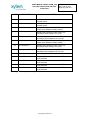
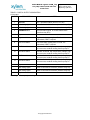
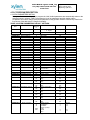
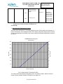
USER’S MANUAL Logimac 480VM_T Up to 4 pumps PLC based control system with color touch screen operator interface Issue date: February 2013 480VM_T FCDN-#226783-v1-Logimac_480VM_T__User_s_Manual.doc TABLE OF CONTENTS .. PAGE System parameters’ default settings..................................................................................................... 3 PLC read-only data registers readings .................................................................................................. 4 1. INTRODUCTION ........................................................................................................................ 5 1.1 Approvals ............................................................................................................................... 5 1.2 Part numbers ......................................................................................................................... 5 2 HARDWARE DESCRIPTION .................................................................................. 6 2.1 PLC configuration .................................................................................................................. 6 2.2 Operator interface ................................................................................................................. 7 3. PLC INPUT & OUTPUT CONNECTIONS ............................................................. 8 4. PLC PROGRAM DESCRIPTION ....................................................................... 12 4.1 Initial parameter writing ....................................................................................................... 12 4.2 Analog input reading & scaling ........................................................................................... 13 4.3 Starting pump choice .......................................................................................................... 15 4.4 Contactor operation ............................................................................................................. 19 4.5 Alarms: memorizing, indication, acknowledge, reset ......................................................... 20 5. OPERATOR INTERFACE PROGRAM DESCRIPTION .................................... 26 5.1 Main Screen ........................................................................................................................ 26 5.2 Parameters Screen ............................................................................................................. 28 5.3 Default Parameters or Cold Start ....................................................................................... 30 5.4 Operational Data Screen ................................................................................................... 32 5.5 Trends ................................................................................................................................. 34 FCDN-#226783-v1-Logimac_480VM_T__User_s_Manual.doc USER’S MANUAL Logimac 480VM_T up to 4 pump control system with color touch screen Page: 3 of 38 Date: February 2013 Replacing: April 2012 SYSTEM PARAMETERS’ DEFAULT SETTINGS FUNCTION KEY Main Screen PARAMETERS PARAMETERS PARAMETERS PARAMETERS PARAMETERS PARAMETERS PARAMETERS PARAMETERS PARAMETERS PARAMETERS PARAMETERS PARAMETERS PARAMETERS PARAMETERS PARAMETERS PARAMETERS PARAMETERS PARAMETERS PARAMETERS PARAMETERS PARAMETERS PARAMETERS PARAMETERS PARAMETERS PARAMETERS PARAMETERS PARAMETERS PARAMETERS PARAMETERS PARAMETERS PARAMETERS PARAMETERS PARAMETERS PARAMETERS PARAMETERS PARAMETERS PLC REGIS TER 225 102 23 24 2 5 613 616 8 11 619 622 20 132 70 72 74 75 625 626 76 77 627 628 107 106 96 98 629 631 111 701 112 704 633 713 634 716 100 707 101 710 635 719 636 722 PARAMETER Language French English New password Number of pumps in OPERation: in PARAllel: Start 1 delay Start 2 delay Start 3 delay Start 4 delay Blocking delay P1 Blocking delay P2 Blocking delay P3 Blocking delay P4 Alarm delay Contactor Closing delay minimum level for 4 mA maximum level for 20mA Start 1 level Start 2 level Start 3 level Start 4 level Stop 1 level Stop 2 level Stop 3 level Stop 4 level High level alarm Low level alarm P1 max. current P2 max. current P3 max. current P4 max. current P1 high current alarm Delay P2 high current alarm Delay P3 high current alarm Delay P4 high current alarm Delay P1 low current alarm Delay P2 low current alarm Delay P3 low current alarm Delay P4 low current alarm Delay Mode Choice INITIAL VALUE ADJUSTED VALUE NOTES English 9 4 4 10 s 10 s 10 s 10 s 15 s 15 s 15 s 15 s 5s 10s 0m 5.00 m 1.00 m 1.20 m 1.40 m 1.60 m 0.50 m 0.50 m 0.50 m 0.50 m 2.00 m 0m 50 A 50 A 50 A 50 A 35 A 30 s 35 A 30 s 35 A 30 s 35 A 30 s 0A 30 s 0A 30 s 0A 30 s 0A 30 s Alternate; all * Available only if number of pumps in OPERation is 4 SB -Stand-By .© Copyright XYLEM 2012 CHOICE: 1... 4 2 ...4 Choice: Alternate all Alternate, P3SB Alternate, P4SB * Alternate, P2SB Alternate, P1SB No ALT, P1Lead No ALT, P2Lead No ALT, P3Lead No ALT, P4Lead* USER’S MANUAL Logimac 480VM_T up to 4 pump control system with color touch screen Page: 4 of 38 Date: February 2013 Replacing: April 2012 PLC READ-ONLY DATA REGISTER READING FUNCTION KEY of OPERATOR INTERFACE PLC REGISTER Operational Data Operational Data Operational Data Operational Data Operational Data Operational Data Operational Data Operational Data Operational Data Operational Data Operational Data Operational Data Operational Data Operational Data Operational Data Operational Data Operational Data Operational Data Operational Data Operational Data Operational Data 146, 143 Runtime P1 total 176, 173 Runtime P1/day 155, 152 Runtime P2 total 185, 182 Runtime P2/day 542, 539 Runtime P3 total 578, 575 Runtime P3/day 551, 548 Runtime P4 total 587, 584 Runtime P4/day 164, 161 2P Runtime total 194, 191 2P Runtime/day 560, 557 3P Runtime total 596, 593 3P Runtime/day 569, 566 4P Runtime total 605, 602 4P Runtime/day 217, 214 Overflow runtime PARAMETER READINGS 1 202 No. of starts P1 205 No. of starts P2 608 No. of starts P3 645 No. of starts P4 208 Hi level occurrences 220 Overflow occurrences 2 .© Copyright XYLEM 2012 3 4 5 6 7 USER’S MANUAL Logimac 480VM_T up to 4 pump control system with color touch screen Page: 5 of 38 Date: February 2013 Replacing: April 2012 INTRODUCTION The LOGIMAC® 480VM_T P/N 13-50 90 96 was designed for the control and supervision of a sewage pumping station with up to four pumps. The complete system consists of programmable logic controller LOGIMAC® 480VM_T-PLC as per the configuration specified in the following chapter, the operator interface LOGIMAC® 480VM_T-OP. A level sensor with 4-20 mA output signal provides the LOGIMAC®480VM_T-PLC with the level data for pump control. 1.1 Approvals Sensor: CSA certified for operation in Class I, Division 2, Groups C and D hazardous environments. (Note: For this approval to be valid special installation conditions apply). 1.2 Part numbers LOGIMAC® 480VM_T-PLC (P/N 13-50 90 97); program L480VM_T ANALOG Expansion unit (P/N 13-40 02 30) Cable RS-232 (P/N 13-40 02 19) LOGIMAC® 480VM_T-OP (P/N 13-50 90 98); program L480VM_T.cpa © Copyright 2012 XYLEM ® The LOGIMAC is registered mark of ITT Flygt (Xylem). All rights reserved. No part of this manual may be reproduced or copied without the written permission of Xylem. .© Copyright XYLEM 2012 USER’S MANUAL Logimac 480VM_T up to 4 pump control system with color touch screen Page: 6 of 38 Date: February 2013 Replacing: April 2012 2. HARDWARE DESCRIPTION 2.1 LOGIMAC® 480VM_T-PLC CONFIGURATION The programmable logic controller (PLC) is composed of the modules specified in the table below CONFIGURATION of LOGIMAC® 480VM_T-PLC: ITEM # DESCRIPTION CPU & Memory TECHNICAL DATA Flash user memory program memory: 24 Kwords storage memory: 32 Kwords operation speed: 1.0 ms/ 1Kword of logic user program: L480VM_T P/N 40 - inputs 24V DC; curent consomption: 7.3mA max./point 24 relays outputs Operating voltage: 5-30 V DC 13-50 90 97 5-250 V AC max. load: 2A resistive/ 0.6A inductive Supply 120V AC ( 102 -132V), 60 Hz (47- 63 Hz) DC output power supply: 24V + -10%, 435 mA max. current Dimensions (90H x 190W x76D) mm service temperature 0..+55°C stocking temperature -40..+85°C Port Two serial ports: 1: RS 232, 2: RS 232 ( BY DEFAULT) Optional port 2: RS485, Ethernet, USB 2 x P/N 13-40 02 30 Removable terminal strip included 2 x Analogue Expansion unit Inputs: current 4-20mA 2 x (4-inputs/2-outputs) outputs: current 4-20mA Supply : 120V AC ( 102 -132V), 60 Hz (47- 63 Hz) Dimensions: 90H x 95W x76D) mm .© Copyright XYLEM 2012 USER’S MANUAL Logimac 480VM_T up to 4 pump control system with color touch screen Page: 7 of 38 Date: February 2013 Replacing: April 2012 2.2 OPERATOR INTERFACE LOGIMAC® 480VM_T-OP The operator interface LOGIMAC® 480VM_T-OP is is a fully programmable man-machine interface. One part of a programming can be done using the software, specific for the unit, and another one should be programmed in the PLC program software for PLC ladder programming. The operator interface is equipped of: 6.5” Touch screen graphic display 640x480 pixels Real-time clock Application memory 12MB 10/100Mbit/s Ethernet port (RJ45) PLC communication port RS 232 RS422/RS485 serial port USB Host & USB device ports cable: operator interface-PLC (DB9F- RG45) The supply voltage 24VDC (20-30V) Power consumption: Normal 0.4A @ 24VDC, Max 0.9A Dimensions: (219 x 154 x 6)mm mounting depth 55 mm Operation temperature 0-+50degC Storage temperature -20 to+70degC FIG.1 Operator interface unit LOGIMAC 480VM_T-OP The operator interface was fully programmed for this application (see description of this programming in chapter 5 of this manual). For further details, please refer to the manufacturer user manual supplied with unit. .© Copyright XYLEM 2012 USER’S MANUAL Logimac 480VM_T up to 4 pump control system with color touch screen Page: 8 of 38 Date: February 2013 Replacing: April 2012 3. LOGIMAC® 480VM_T-PLC INPUT & OUTPUT CONNECTION LOGIMAC® 480VM_T-PLC has 40 digital inputs, 24 digital relay-based outputs and 8 analog 4-20 mA inputs. For this application the inputs and outputs are assigned to the signals specified in the table 1, 2 and 3 respectively. TABLE 1.: DIGITAL INPUT ASSIGNATION a) 40- inputs INPUT DESCRIPTION NOTES 1 ACKNOWLEDGE/ RESET signal provided by push button “ACKNOWLEDGE/ RESET on the alarm annunciator 2 M1 contactor closed auxiliary contact of the M1 contactor to indicate the contactor status 3 M2 contactor closed auxiliary contact of the M2 contactor to indicate the contactor status 4 B1 (OL1) contact indicating overload of the P1 pump or breaker open (breaker auxiliary contact) 5 R6 leakage P1 interface relay contact from Mini CAS II unit indicating a water leakage in P1 pump 6 R5 high temp. P1 interface relay contact from Mini CAS II unit indicating a high temperature in P1 pump 7 B2 (OL2) contact indicating overload of the P2 pump or breaker open(breaker auxiliary contact) 8 R8 leakage P2 interface relay contact from Mini CAS II unit indicating a water leakage in P2 pump 9 R7 high temp.P2 interface relay contact from Mini CAS II unit indicating a high temperature in P2 pump 10 FLH (ISRH) interface relay contact indicating the high level reached (follows FL.H float NO contact) 11 Overflow (optional) Contact indicating the overflow level reached. 12 PFD voltage or phase failure detection (PFD) 13 Genset run Contact to limit the number of pumps allowed in parallel operation 14 spare 15 spare 16 FLL(ISRL ) Contact indicating the low level reached (follows FLL float NC contact) For wiring details see project drawing .© Copyright XYLEM 2012 USER’S MANUAL Logimac 480VM_T up to 4 pump control system with color touch screen INPUT DESCRIPTION Page: 9 of 38 Date: February 2013 Replacing: April 2012 NOTES 17 M3 contactor closed auxiliary contact of the M3 contactor to indicate the contactor status 18 M4 contactor closed auxiliary contact of the M4 contactor to indicate the contactor status 19 B3 (OL3) contact indicating overload of the P3 pump or breaker open (breaker auxiliary contact) 20 R10 leakage. P3 interface relay contact from Mini CAS II unit indicating a water leakage in P3 pump 21 R9 high temp. P3 interface relay contact from Mini CAS II unit indicating a high temperature in P3 pump 22 B4 (OL4) contact indicating overload of the P4 pump or breaker open (breaker auxiliary contact) 23 R12 leakage P4 interface relay contact from Mini CAS II unit indicating a water leakage in P4 pump 24 R11 high temp.P4 interface relay contact from Mini CAS II unit indicating a high temperature in P4 pump Spare Future usage 37 P1 AUTO Pump 1 operation mode selector in AUTO position mode automatic 38 P2 AUTO 39 P3 AUTO 40 P4 AUTO Pump 2 operation mode selector in AUTO position mode automatic Pump 3 operation mode selector in AUTO position mode automatic Pump 4 operation mode selector in AUTO position mode automatic 25-36 For wiring details see project drawing. .© Copyright XYLEM 2012 USER’S MANUAL Logimac 480VM_T up to 4 pump control system with color touch screen Page: 10 of 38 Date: February 2013 Replacing: April 2012 TABLE 2.: DIGITAL OUTPUT ASSIGNATION a) 24-output OUTPUT DESCRIPTION NOTES 1 PLC OK PLC operational status (active if PLC OK) 2 M1 closing signal order to close the M1 contactor (interface relay R1) 3 M2 closing signal order to close the M2 contactor (interface relay R2) 4 COMMON alarm Common alarm signal for remote transmission (interface relay R14) 5-6 Spare 7 High Level Alarm High Level alarm coming from FLH float. It is maintained, RESET required. 8 Low Level Alarm Low Level alarm coming from FLL float. It is maintained, RESET required. 9 P1 Failure Alarm Includes: Overload, high temperature, leakage, high or low current, contactor closing fault for pump P1 10 P2 Failure Alarm Includes: Overload, high temperature, leakage, high or low current, contactor closing fault for pump P2 11 P3 Failure Alarm Includes: Overload, high temperature, leakage, high or low current, contactor closing fault for pump P3 12 P4 Failure Alarm Includes: Overload, high temperature, leakage, high or low current, contactor closing fault for pump P4 13-16 Spare 17 M3 closing signal order to close the M3 contactor (interface relay R3) 18 M4 closing signal order to close the M4 contactor (interface relay R4) 19-24 Spare For wiring details see project drawing .© Copyright XYLEM 2012 USER’S MANUAL Logimac 480VM_T up to 4 pump control system with color touch screen Page: 11 of 38 Date: February 2013 Replacing: April 2012 TABLE 3 ANALOG INPUT ASSIGNATION INPUT DESCRIPTION Notes 1 Level signal Level signal from a 4-20 mA sensor. Use the operator interface for scaling 2 P1 current signal P1 pump current signal 4-20mA from current (optional) transducer. Use the operator interface for scaling 3 P2 current signal P2 pump current signal 4-20mA from current (optional) transducer. Use the operator interface for scaling 4 P3 current signal P3 pump current signal 4-20mA from current (optional) transducer. Use the operator interface for scaling 5 P4 current signal P4 pump current signal 4-20mA from current (optional) transducer. Use the operator interface for scaling 6 Flow signal from Inflow signal 4-20mA from Flowmeter. Use the Flowmeter (optional) operator interface for scaling 7 spare 4-20mA signal Future application 8 spare 4-20mA signal Future application For wiring details see project drawing TABLE 4 ANALOG OUTPUT ASSIGNATIONS OUTPUT 1 2 3 4 DESCRIPTION SPARE SPARE SPARE SPARE Notes 4-20mA signal Future application 4-20mA signal Future application 4-20mA signal Future application 4-20mA signal Future application .© Copyright XYLEM 2012 USER’S MANUAL Logimac 480VM_T up to 4 pump control system with color touch screen Page: 12 of 38 Date: February 2013 Replacing: April 2012 4. PLC PROGRAM DESCRIPTION 4.1 INITIAL PARAMETERS WRITING During the first scan or coldstart of the program the initial default parameters are automatically written to the assigned memory registers. TABLE 4 presents the list of the parameters and their default values. An operator can read or change (write) these parameters using operator interface function keys listed in the first column of the table (see 5.2 chapter for details). TABLE 4: SYSTEM PARAMETERS’ DEFAULT SETTINGS FUNCTION KEY 1 FUNCTION KEY 2 Main Screen - PLC REGISTE R 225 PARAMETER PARAMETERS PARAMETERS PARAMETERS PARAMETERS PARAMETERS PARAMETERS PARAMETERS PARAMETERS PARAMETERS PARAMETERS PARAMETERS PARAMETERS PARAMETERS PARAMETERS PARAMETERS PARAMETERS PARAMETERS PARAMETERS PARAMETERS PARAMETERS PARAMETERS PARAMETERS PASS change DELAYS Settings DELAYS Settings DELAYS Settings DELAYS Settings DELAYS Settings DELAYS Settings DELAYS Settings DELAYS Settings DELAYS Settings DELAYS Settings LEVEL Scaling LEVEL Scaling LEVELS Setting LEVELS Setting LEVELS Setting LEVELS Setting LEVELS Setting LEVELS Setting LEVELS Setting LEVELS Setting LEVELS Setting 102 2 5 613 616 8 11 619 622 20 132 70 72 74 75 625 626 76 77 627 628 107 106 Language F - French E - English New password Start 1 delay Start 2 delay Start 3 delay Start 4 delay Blocking delay P1 Blocking delay P2 Blocking delay P3 Blocking delay P4 Alarm delay Contactor Closing delay minimum level for 4 mA maximum level for 20mA Start 1 level Start 2 level Start 3 level Start 4 level Stop 1 level Stop 2 level Stop 3 level Stop 4 level High level alarm Low level alarm PARAMETERS PARAMETERS PARAMETERS PARAMETERS PARAMETERS CURRENT Scaling CURRENT Scaling CURRENT Scaling CURRENT Scaling CURRENTS Settings 96 98 629 631 111 701 P1 max. current P2 max. current P3 max. current P4 max. current P1 high current alarm Delay PARAMETERS CURRENTS Settings 112 704 P2 high current alarm Delay PARAMETERS CURRENTS Settings 633 713 P3 high current alarm Delay PARAMETERS CURRENTS Settings 634 716 P4 high current alarm Delay PARAMETERS CURRENTS Settings 100 707 P1 low current alarm Delay PARAMETERS CURRENTS Settings 101 710 P2 low current alarm Delay PARAMETERS CURRENTS Settings 635 719 P3 low current alarm Delay PARAMETERS CURRENTS Settings 636 722 P4 low current alarm Delay PARAMETERS Mode of operation 23 24 2000 2001 Number of pump in OPERation: in PARAllel: Number of pumps: Jockey Normal Storm .© Copyright XYLEM 2012 INITIAL VALUE NOTES E - English 9 10 s 10 s 10 s 10 s 15 s 15 s 15 s 15 s 5s 10s 0m 5.00 m 1.00 m 1.20 m 1.40 m 1.60 m 0.50 m 0.50 m 0.50 m 0.50 m 2.00 m 0m 50 A 50 A 50 A 50 A 35 A 30 s 35 A 30 s 35 A 30 s 35 A 30 s 0A 30 s 0A 30 s 0A 30 s 0A 30 s 4 4 Choice: 1..4 2..4 0 4 0..1 2..4 USER’S MANUAL Logimac 480VM_T up to 4 pump control system with color touch screen Page: 13 of 38 Date: February 2013 Replacing: April 2012 2002 0 Standby pump choice !!All pumps have to be Normal!! 0..1 Alternate all 1803 Alternate all Alternate, P3SB Alternate, P4SB * Alternate, P2SB Alternate, P1SB Lead pump choice 1800 No ALT, P1Lead No ALT, P2Lead No ALT, P3Lead No ALT, P4Lead* * Available only if number of pumps in OPERation is 4 SB -Stand-By 4.2 ANALOG INPUT READING & SCALING All analog inputs are based on 12-bit analog-digital converter. During each scan of program 12 bits are converted in 16-bit analog data word %AI. Factory scaling for analog inputs of 4-20 mA and the corresponding level and the pump current scaling for the default ranges are provided on fig.2 and 3. 3200 3.2 2800 2.8 2400 2.4 2000 2.0 1600 1.6 1200 1.2 800 0.8 400 0.4 0 0 1 2 3 4 5 6 7 8 9 1 1 1 1 1 1 1 1 1 1 2 Water levei in m value in PLC LOGIMAC 480 PLC analog input (Level sensor) 0 sensor current in mA FIG. 2 ANALOG INPUT SCALING (LEVEL) The scaling will be automatically changed by PLC if an operator provides different values of ranges using the operator interface. Exemple for the range 0-5m .© Copyright XYLEM 2012 USER’S MANUAL Logimac 480VM_T up to 4 pump control system with color touch screen Page: 14 of 38 Date: February 2013 Replacing: April 2012 Level scaling 5 4.5 4 Level in m 3.5 3 Series1 2.5 2 1.5 1 0.5 0 0 5 10 15 20 mA LOGIMAC 480 PLC analog input (current sensor) 5 3200 4 2800 4 2400 Value in PLC 2000 3 2 1600 2 1200 pump's current in A 3 1 800 1 400 0 5 0 1 2 3 4 5 6 7 8 9 1 1 1 1 1 1 1 1 1 1 2 0 sensor current in mA FIG.3 ANALOG INPUT SCALING( CURRENT) If the inputs of pumps’ currents are not used, no changes are required in default values of ranges. The PLC will treat these inputs as a zero signal. .© Copyright XYLEM 2012 USER’S MANUAL Logimac 480VM_T up to 4 pump control system with color touch screen Page: 15 of 38 Date: February 2013 Replacing: April 2012 4.3 STARTING PUMP CHOICE The control system allows the operation of up to four pumps in parallel (operator choice) but prevents simultaneous start of two or more pumps. The pumps operation depends on pump group setting. Maximum 3 different groups can be chosen: group N-Normal, group J-Jockey, group S- Storm N - Normal (minimum 2) these pumps will work in normal and high level condition. They can work together if the number of pumps in Parallel is set > 1. J - Jockey: if J=1, P1 will be called a jockey–pump. Usually this pump will be smaller than Normal pumps. This pump will always start first. Its purpose is to pump during a low inflow. Once the inflow rises above the jockey pump capacity and the second start level reaches, the normal pump will start and the jockey pump will stop. If J=2, P1 & P2 will be the jockey pumps. P1 & P2 will alternate but never run together. S – Storm - usually pump larger than Normal pumps, designed to work only in case of an extreme high inflow (storm). If S=1 P4 is storm pump. If S=2 than P3 & P4 are the storm pumps. The storm pumps can alternate or not. They also can work together and with normal pumps depending on setting of Pnumber of pumps in parallel operation. See table below for setting the desired operation N 4 4 4 4 J 0 0 0 0 S 0 0 0 0 P 4 3 2 1 3 3 3 0 0 0 0 0 0 3 2 1 3 1 0 3 3 1 0 2 3 1 0 1 2 1 0 2 2 1 0 1 2 2 0 2 2 2 0 1 3 0 1 4 3 0 1 3 Operation description All 4 pumps alternate; All 4 pumps can work together (in parallel) All 4 pumps alternate; Only 3 pumps can work together (in parallel) All 4 pumps alternate; Only 2 pumps can work together (in parallel) All 4 pumps alternate; Only 1 pump can run at the time (no parallel operation) All 3 pumps alternate; All 3 pumps can work together (in parallel) All 3 pumps alternate; Only 2 pumps can work together (in parallel) All 3 pumps alternate; Only 1 pump can run at the time (no parallel operation) P1-jockey pump always starts first. P2,P3, P4 alternate and all can work together (in parallel). P1 stops if the first of the normal pumps starts. P1-jockey pump always starts first. P2,P3, P4 alternate and 2 of them can work together (in parallel). P1 stops if the first of the normal pumps starts. P1-jockey pump always starts first (START 1). P2,P3, P4 alternate but only one of the can run at the time (no parallel operation). P1 stops if the normal pump starts. P1-jockey pump always starts first. P2,P3 alternate and both can work together (in parallel). P1 stops if the first of the normal pumps starts. P1-jockey pump always starts first. P2, P3 alternate but only one of them can run at the time (no parallel operation). P1 stops if the normal pump starts. P1, P2-jockey pumps; one of them (P1/P2) always starts first (START 1); They alternate but never work in parallel. P3,P4 alternate and both can work together (in parallel). P1/P2 stops if the first of the normal pumps starts (on START 2). P1, P2-jockey pumps; one of them (P1/P2) always starts first (START 1) They alternate but never work in parallel. P3, P4 alternate but only one of them can run at the time (no parallel operation). P1/P2 stops if the normal pump starts (on START 2). P1, P2, P3, normal pumps. They alternate. P4-storm pump All 4 pumps can work together (in parallel) P1, P2, P3 - normal pumps. They alternate. P4-storm pump. Only 3 normal pumps can work together (in parallel). Normal pumps stop .© Copyright XYLEM 2012 USER’S MANUAL Logimac 480VM_T up to 4 pump control system with color touch screen Page: 16 of 38 Date: February 2013 Replacing: April 2012 if P4 starts (START 4). N 3 J 0 S 1 P 2 3 0 1 1 2 0 1 3 2 0 1 2 2 0 1 1 2 0 2 4 2 0 2 3 2 0 2 2 2 0 2 1 2 1 1 3 2 1 1 2 2 1 1 1 Operation description P1, P2, P3, normal pumps. They alternate. P4-storm pump. Only 2 normal pumps can work together (in parallel). Normal pumps stop if P4 starts (START3). P1, P2, P3, normal pumps. They alternate. P4-storm pump. Only 1 normal pump can run at the time (no parallel operation). Normal pump stops if P4 starts (START 2). P1, P2 normal pumps. They alternate. P3-storm pump All 3 pumps can work together (in parallel) P1, P2 normal pumps. They alternate. P3-storm pump Only 2 normal pump can work together (in parallel). Normal pumps stop if P3 starts (START 3). P1, P2 normal pumps. They alternate. P3-storm pump Only 1 normal pumps can run at the time (no parallel operation)). Normal pump stops if P3 starts (START 2). P1, P2 - normal pumps. P3, P4-storm pumps. The pumps alternate within their group. All 4 pumps can work together (in parallel) P1, P2 - normal pumps. P3, P4-storm pumps. The pumps alternate within their group. Only 3 pumps can work together (in parallel: 2 normal + 1storm) P1, P2 - normal pumps. P3, P4-storm pumps. The pumps alternate within their group. 2 normal or 2 storm pumps can work together (in parallel). Normal pumps stop if the first of storm pumps starts (START3). P1, P2 - normal pumps. They alternate but only 1 normal pump can run at the time (no parallel operation). P3, P4-storm pumps. Normal pump stops if the first of storm pumps starts (START 2). P1-jockey pump always starts first. P1 stops if the normal pump starts.P2, P3, normal pumps. They alternate. P4-storm pump. All normal and storm pumps (3) can work together (in parallel). P1-jockey pump always starts first. P1 stops if the normal pump starts. P2, P3, normal pumps. They alternate. P4-storm pump. Only 2 normal pumps can work together (in parallel). Normal pumps stop if P4 starts (START4). P1-jockey pump always starts first. P1 stops if the normal pump starts. P2, P3, normal pumps. They alternate. P4-storm pump. Only 1 normal pump can run at the time (no parallel operation).Normal pump stop if P4 starts (START3). Note: Total number of pumps N+J+S can’t be higher than 4. The system will reset to default setting (N=4.J=0, S=0, P=4) if during a setup the total 4 is exceeded. If all pumps available are set as Normal the additional mode settings of STANDBY PUMP or LEADING PUMP is available The pumps’ starting sequence depend on: - the number of pumps in OPERation, - the number of pumps allowed to run in PARAllel - the operation mode setting :(Alternate all; Alternate &P4SB ; Alternate &P3SB, Alternate &P2SB; Alternate &P1SB; No Alternate &P1Lead; No Alternate &P2Lead; No Alternate &P3Lead; No Alternate &P4Lead.) For the given setting the pumps will operate as shown in the table below MODE Operation description OPERation PARAllel 3 3 Alternate all All pumps alternate in sequences 1,2,3: 1: P1-P2-P3; 2:P2-P3-P1; 3: P3-P1-P2 3 2 Alternate all All pumps alternate in sequences 1,2,3: 1: P1-P2; 2:P2-P3; 3: P3-P1 .© Copyright XYLEM 2012 USER’S MANUAL Logimac 480VM_T up to 4 pump control system with color touch screen 3 2 Alternate &P3SB, 3 2 Alternate &P2SB, 3 2 Alternate &P1SB, 4 DEFAULT Alternate all DEFAULT 4 4 DEFAUL T 3 Alternate all 4 2 Alternate all 4 3 Alternate &P4SB, 4 2 Alternate &P4SB, 4 3 Alternate &P3SB, 4 2 Alternate &P3SB, 4 3 Alternate &P2SB, 4 2 Alternate &P2SB, 4 3 Alternate &P1SB, 4 2 Alternate &P1SB, 3 3 No Alternate P1LEAD 3 2 No Alternate P1LEAD 3 3 No Alternate P2LEAD 3 2 No Alternate P2LEAD 3 3 No Alternate P3LEAD 3 2 No Alternate P3LEAD Page: 17 of 38 Date: February 2013 Replacing: April 2012 2 pumps alternate in sequences 1,2: 1: P1-P2; 2:P2-P1; P3 starts only if P1 or P2 is out of order 2 pumps alternate in sequences 1,3: 1: P1-P3; 2:P3-P1; P2 starts only if P1 or P3 is out of order 2 pumps alternate in sequences 2,3: 1: P2-P3; 2:P3-P2; P1 starts only if P2 or P3 is out of order All pumps alternate in sequences 1,2,3,4: 1: P1-P2-P3-P4; 2:P2-P3-P4-P1; 3: P3-P4-P1-P2; 4:P4-P1-P2-P1 All pumps alternate in sequences 1,2,3,4: 1: P1-P2-P3; 2:P2-P3-P4; 3: P3-P4-P1; 4:P4-P1-P2 All pumps alternate in sequences 1,2,3,4: 1: P1-P2; 2:P2-P3; 3: P3-P4; 4:P4-P1 3 pumps alternate in sequences 1,2,3: 1: P1-P2-P3; 2:P2-P3-P1; 3: P3-P1-P2; P4 starts only if P1or P2 or P3 is out of order 3 pumps alternate in sequences 1,2,3: 1: P1-P2; 2:P2-P3; 3: P3-P1; P4 starts only if P1or P2 or P3 is out of order 3 pumps alternate in sequences 1,2,4: 1: P1-P2-P4; 2:P2-P4-P1; 4: P4-P1-P2; P3 starts only if P1or P2 or P4 is out of order 3 pumps alternate in sequences 1,2,4: 1: P1-P2; 2:P2-P4; 4: P4-P1; P3 starts only if P1or P2 or P4 is out of order 3 pumps alternate in sequences 1,3,4: 1: P1-P3-P4; 3:P3-P4-P1; 4: P4-P1-P3; P2 starts only if P1or P3 or P4 is out of order 3 pumps alternate in sequences 1,3,4: 1: P1-P3; 3:P3-P4; 4: P4-P1; P2 starts only if P1or P3 or P4 is out of order 3 pumps alternate in sequences 2,3,4: 2: P2-P3-P4; 3:P3-P4-P2; 4: P4-P2-P3; P1 starts only if P4or P2 or P3 is out of order 3 pumps alternate in sequences 2,3,4: 2: P2-P3; 3:P3-P4; 4: P4-P2; P1 starts only if P4or P2 or P3 is out of order ALWAYS THE SAME SEQUENCE 1: P1-P2-P3 ALWAYS THE SAME SEQUENCE 1: P1-P2; P3 starts only if P1 or P2 is out of order ALWAYS THE SAME SEQUENCE 2: P2-P3-P1 ALWAYS THE SAME SEQUENCE 2: P2-P3; P1 starts only if P2 or P3 is out of order ALWAYS THE SAME SEQUENCE 3: P3-P1-P2 ALWAYS THE SAME SEQUENCE 3: P3-P1; P2 starts only if P1 or P3 is out of order .© Copyright XYLEM 2012 USER’S MANUAL Logimac 480VM_T up to 4 pump control system with color touch screen 4 4 No Alternate P1LEAD 4 3 No Alternate P1LEAD 4 2 No Alternate P1LEAD 4 4 No Alternate P2LEAD 4 3 No Alternate P2LEAD 4 2 No Alternate P2LEAD 4 4 No Alternate P3LEAD 4 3 No Alternate P3LEAD 4 2 No Alternate P3LEAD 4 4 No Alternate P4LEAD 4 3 No Alternate P4LEAD 4 2 No Alternate P4LEAD Page: 18 of 38 Date: February 2013 Replacing: April 2012 ALWAYS THE SAME SEQUENCE 1: P1-P2-P3-P4 ALWAYS THE SAME SEQUENCE 1: P1-P2-P3 P4 starts only if P1 or P2 or P3 is out of order ALWAYS THE SAME SEQUENCE 1: P1-P2; P3 starts only if P1 or P2 is out of order P4 starts only if two pumps are out of order ALWAYS THE SAME SEQUENCE 2: P2-P3-P4 ALWAYS THE SAME SEQUENCE 2: P2-P3-P4 P1 starts only if P4 or P2 or P3 is out of order ALWAYS THE SAME SEQUENCE 2: P2-P3; P4 starts only if P3 or P2 is out of order P1 starts only if two pumps are out of order ALWAYS THE SAME SEQUENCE 3: P3-P4-P1-P2 ALWAYS THE SAME SEQUENCE 3: P3-P4-P1 P2 starts only if P1 or P4 or P3 is out of order ALWAYS THE SAME SEQUENCE 3: P3-P4; P1 starts only if P3 or P4 is out of order P2 starts only if two pumps are out of order ALWAYS THE SAME SEQUENCE 4: P4-P1-P2-P3 ALWAYS THE SAME SEQUENCE 4: P4-P1-P2 P2 starts only if P1 or P4 or P3 is out of order ALWAYS THE SAME SEQUENCE 4: P4-P1; P2 starts only if P1 or P4 is out of order P3 starts only if two pumps are out of order The default settings are: # of pumps in OPERation: 4, # pumps are allowed to run in PARAllel: 4; MODE Alternate. All settings are password protected In automatic mode the choice of the pump start sequence is done automatically following the previous cycle of operation memorized conditions. If no sequence is memorized or if no alternate mode is chosen the pumps will start following the SEQUENCE 1(P1, P2, P3, P4). On the event of the pump failure, the pump next in sequence, will receive the order to start with respect to level conditions and the number of pumps allowed in parallel operation. To start the pump, either the start conditions should be kept during at least 10-second period calling START DELAY. The default value of 10 seconds can be changed by operator (see TIME DELAY CHANGE in chapter 5.2) .© Copyright XYLEM 2012 USER’S MANUAL Logimac 480VM_T up to 4 pump control system with color touch screen Page: 19 of 38 Date: February 2013 Replacing: April 2012 If one of the pumps is stopped (for whatever reason) the BLOCKING DELAY will be activated. None of the pumps can start during this period (all pumps will be prevented to start). If more pumps are running and one of them stops, this delay will not have effect on the running pumps. The default value of the BLOCKING DELAY are 15 s and can be adjusted by operator using operator interface for each pump separately (see TIME DELAY CHANGE in chapter 5.2). 4.4 CONTACTOR OPERATION In automatic mode the pump contactor (M1, M2, M3, M4) will close following the closing signal from corresponding interface relay (R1, R2, R3 or R4) after START DELAY as specified in previous chapter. The reception of the contactor closing confirmation by PLC will be indicated by turning on the respective PUMP P1, PUMP P2, PUMP P3 or PUMP P4 on the Main Screen NOTE: Closing fault: If PLC does not receive a confirmation of the contactor closing (see M1, M2, M3, M4 contacts connected to PLC inputs) during the 10-second period following the closing order ( R1, R2, R3 or R4 relay contact closing), the closing order will be removed and the alarm will be signaled. In automatic mode, if stop conditions are reached (STOP 1, 2 , 3, 4 levels) and are held during the STOP DELAY, the contactors will open following the reversed start sequence (the rule LIFO : Last In First Out). Each contactor can be opened or closed manually, using a mode selector MAN-OFF-AUTO ( MAN-OFF positions). Either during manual or automatic operation the contactor opens automatically on fault conditions of the respective pump. .© Copyright XYLEM 2012 USER’S MANUAL Logimac 480VM_T up to 4 pump control system with color touch screen Page: 20 of 38 Date: February 2013 Replacing: April 2012 4.5 ALARMS : Memorizing, indication, acknowledge, reset. The following alarms can be stored in the operator interface memory: Pumps` alarms for each pump: Overload Contactor closing fault Leakage High temperature Low current High current No automatic mode (warning) Well alarms: High Level Low Level Overflow Supply alarm Power failure If any alarm is active alarm BEL will appear on the high right corner of the Main Screen Touch Alarm LOGGER to go to the alarm page .© Copyright XYLEM 2012 USER’S MANUAL Logimac 480VM_T up to 4 pump control system with color touch screen Page: 21 of 38 Date: February 2013 Replacing: April 2012 ALARM PAGE Back to MAIN SCREEN (2) *OVERLOAD P1 (1) $OVERLOAD P2 (1) -LEAKAGE P2 (1) OVERLOAD P1 Alarms’ ACKNOWLEDGE in operator interface Alarms’ RESET in PLC Visualization of the time of alarm activation Prefix Legend: (1) - Number of alarm’s occurrences before acknowledge * - Active alarm, no acknowledged $ - Alarm no active, unacknowledged - - Active alarm, but acknowledged Void- alarms no active & acknowledged For alarm acknowledge in operator interface, touch the alarm description first, then the button with check mark . For alarm acknowledge/RESET in PLC, correct the fault first and then touch the RST button (once for acknowledge and twice for RESET). Using the RESET P.B connected to the input 1 of the PLC will do the same job. .© Copyright XYLEM 2012 USER’S MANUAL Logimac 480VM_T up to 4 pump control system with color touch screen Page: 22 of 38 Date: February 2013 Replacing: April 2012 To see the time of the alarm occurrences and acknowledge touch the button with clock (2) S 09-12-01 9:54:14 OVERLOAD P1 (1) S 09-12-01 8:43:58 OVERLOAD P2 (1) S 09-11-25 16:01:52 LEAKAGE P2 (1) S 09-11-25 15:00:52 OVERLOAD P1 By touching consecutively the button with clock Where: S - Time of alarm activation E - Time of alarm disappearance A - Time of alarm acknowledge , you can see different times with prefix S, E, A 4.5.1 P1 / P2 / P3 / P4 PUMP OVERLOAD On the overload fault, the respective pump breaker opens. Auxiliary contacts of breakers are used as the overload signal for PLC inputs (B1, B2, B3 or B4). If one of contacts is closed, the corresponding contactor closing signal will be removed (see R1, R2, R3, R4 relay) and the OVERLOAD alarm will be memorized in PLC and operator interface memories. This alarm will be held, even if the fault conditions disappear. The contactor of the pump in fault will open automatically and cannot be closed without an operator’s intervention. Reset the circuit after the fault correction: push the RESET push-button (Alarm Page) once for acknowledge, and twice for reset. 4.5.2. M1/M2/M3/M4 contactor CLOSING FAULT If the PLC does not receive the confirmation of the contactor closing (see M1 or M2 contact as PLC inputs) during the 10-second period following the closing order (R1 or R2 relay contact closing), the closing order will be removed and the alarm M1/M2 contactor closing fault will be registered in PLC and operator interface memories. This alarm will be held, even if the fault conditions disappear. Reset the circuit after the fault correction: push the RESET push-button once for acknowledge and twice for reset, or use RST P.B. on the operator interface alarms’ page. .© Copyright XYLEM 2012 USER’S MANUAL Logimac 480VM_T up to 4 pump control system with color touch screen Page: 23 of 38 Date: February 2013 Replacing: April 2012 4.5.3.ALARM: WATER LEAKAGE OF P1 / P2 / P3 / P4 PUMP The faults detection will be done by the sensors attached to Mini CAS II units of ITT Flygt. The interface relay of this unit (R6, R8, R10, R12) operates if water is detected in the corresponding pump (P1, P2, P3, P4). The contact of this relay is connected to PLC input to provide the information. If one of these contacts is closed, the corresponding contactor closing signal will be removed (See R1, R2, R3, R4 relays) and the alarm LEAKAGE will be memorized in PLC & operator interface memories. This alarm will be held, even if the fault conditions disappear. The contactor of the pump in fault will open automatically and cannot be closed without an operator’s intervention. Reset the circuit after the fault correction: push the RESET push-button (Alarm Page) once for acknowledge, and twice for reset. 4.5.4. ALARM: HIGH TEMPERATURE OF P1 / P2 / P3 / P4 PUMP The faults detection will be done by the sensors attached to Mini CAS II units of Flygt. The interface relay of this unit (R5, R7, R9 or R11) operates if a temperature of pump goes higher than sensor adjustment in the corresponding pump. The contact of this relay is connected to PLC input to supply the information. If one of these contacts is closed, the corresponding contactor closing signal will be removed ( see R1, R2, R3, R4 relay) and the alarm HIGH TEMPERATURE will be memorized in PLC & operator interface memories. This alarm will be held, even if the fault conditions disappear. The contactor of the pump in fault will open automatically and cannot be closed without an operator intervention. Reset the circuit after the fault correction by pushing MiniCAS RESET first and then push the RESET push-button once for acknowledge and twice for reset, or use RST P.B. on the operator interface alarms’ page. 4.5.5. ALARM: HIGH LEVEL The fault detection will be done by FLH float. The normally open contact (NO) of the ISRH interface relay is connected to the PLC input. If this contact is closed, a HIGH LEVEL alarm will be memorized in PLC (output Q7) & operator interface memories. The R14 relay will operate (its NO contact is available for transmission of ALARM signal remotely). This alarm will be held, even if the fault conditions disappear. Reset the circuit after the fault correction: push the RESET push-button once for acknowledge and twice for reset, or use RST P.B. on the operator interface alarms’ page. 4.5.6. ALARM: LOW WATER LEVEL The faults detection will be done by FLL float. The normally open contact (NO) of ISRL interface relay is connected to the PLC input. If this contact is closed, a LOW LEVEL alarm will be memorized in PLC (output Q8) & operator interface memories. This alarm will be held, even if the fault conditions disappear. The R14 relay will operate (its NO contact is available for transmission of ALARM signal remotely) .© Copyright XYLEM 2012 USER’S MANUAL Logimac 480VM_T up to 4 pump control system with color touch screen Page: 24 of 38 Date: February 2013 Replacing: April 2012 Reset the circuit after the fault correction: push the RESET push-button once for acknowledge and twice for reset, or use RST P.B. on the operator interface alarms’ page. 4.5.7. ALARM: POWER FAILURE The faults detection will be done by the power failure detector (PFD) connected to three phases of the power entrance. The PFD operates on phase or power failure. Its NC contact is opened if three phases are present and voltage value is between adjusted limits. On fault this contact will close. If this contact is closed, the contactor closing signals will be removed (see R1, R2, R3, R4 relay) and the alarm POWER FAILURE will be memorized in PLC & operator interface memories. This alarm is maintained if fault conditions disappear but the pumps can start if the power is back to normal Reset the circuit after the fault correction: push the RESET push-button once for acknowledge and twice for reset, or use RST P.B. on the operator interface alarms’ page. 4.5.8. ALARM: P1 / P2 / P3 / P4 PUMP LOW CURRENT If the pump current analog inputs are used these alarms can be available. The limit values for these alarms can be provided by an operator using the operator interface (see chapter 5.2 for details). The default values are established as zero (0) Amps. The 30-seconde delay (by default) prevents the activation of the alarm during transient conditions. An operator can change these values for the LOWEST POSSIBLE CURRENT established during pump’s running test. If current value is lower than established lowest value for respective pump, the PUMP LOW CURRENT alarm will be registered in PLC & operator interface memories This alarm will be held, even if the fault conditions disappear. The contactor of the pump in fault will open automatically and cannot be closed without an operator’s intervention. Reset the circuit after the fault correction: push the RESET push-button once for acknowledge and twice for reset, or use RST P.B. on the operator interface alarms’ page. 4.5.9. ALARM: P1 / P2 / P3 / P4 PUMP HIGH CURRENT If pump current analog inputs are used these alarms can be available. The limit values for these alarms can be provided by an operator using the operator interface (see chapter 5.2 for details). The default values are established on 35 Amps. An operator can change these values for the HIGHEST POSSIBLE CURRENT established during pump’s running test. If current value is higher than established highest value for respective pump, the PUMP HIGH CURRENT alarm will be registered PLC & operator interface memories. The 30-second delay (by default) prevents the activation of the alarm during transient conditions. This alarm will be held, even if fault conditions disappear. The contactor of the pump in fault will open automatically and cannot be closed without an operator’s intervention. Reset the circuit after the fault correction: push the RESET push-button once for acknowledge and twice for reset, or use RST P.B. on the operator interface alarms’ page. 4.5.10. ALARM Output: P1 / P2 / P3 / P4 PUMP Failure The following alarms activate the corresponding output Q9, Q10, Q11, Q12 as corresponding pump failure P1, P2, P3, and P4: - Overload - Contactor closing fault - Leakage - High Temperature .© Copyright XYLEM 2012 USER’S MANUAL Logimac 480VM_T up to 4 pump control system with color touch screen - Page: 25 of 38 Date: February 2013 Replacing: April 2012 Low /High current 4.5.11. Alarm Output (Q4): COMMON ALARM All alarms described above will activate the COMMON ALARM OUTPUT with R14 interface relay. The contacts of this relay are available to remote control or indication. If all active alarms are acknowledged, the common alarm output is de-activated 4.5.12. Alarm Output (Q1): PLC failure If PLC is functioning correctly the output Q1 is activated. In case of internal PLC fault or external PLC supply fault the output Q1 will be not energized. Use the normally closed contact of the interposing relay R15 attached to this output for alarm transmission. .© Copyright XYLEM 2012 USER’S MANUAL Logimac 480VM_T up to 4 pump control system with color touch screen Page: 26 of 38 Date: February 2013 Replacing: April 2012 5. OPERATOR INTERFACE PROGRAM DESCRIPTION Using the operator interface, an operator can : read or change PLC current date & time read the parameters and data stored in the PLC data registers write/change the system operating parameters (password protected) read the alarm register in order of the occurrence monitor the alarms see historic values: TRENDS reset all parameters to their default values (cold start) 5.1 MAIN SCREEN To change the date or time touch the digital clock .© Copyright XYLEM 2012 USER’S MANUAL Logimac 480VM_T up to 4 pump control system with color touch screen Page: 27 of 38 Date: February 2013 Replacing: April 2012 The keyboard will appear to allow you to write /correct the date and time if needed Correct the date and time keeping the same format: yy-mm-dd hh:mm:ss for 24hours system .© Copyright XYLEM 2012 USER’S MANUAL Logimac 480VM_T up to 4 pump control system with color touch screen Page: 28 of 38 Date: February 2013 Replacing: April 2012 5.2. PARAMETERS’ SCREENS Some operational parameters are shown on the main screen. They are read only values. To change them, touch PARAMETERS. This action is protected by PASWORD so the keyboard to write the password will appear. Write password (default is 9), and touch and the screen of the parameter group will appear: Choose the group of parameters you want to see or change and the corresponding screen will appear .© Copyright XYLEM 2012 USER’S MANUAL Logimac 480VM_T up to 4 pump control system with color touch screen Touch the value you want to change. The keyboard will appear: Write the value and touch Proceed with other parameter or parameters’ group .© Copyright XYLEM 2012 Page: 29 of 38 Date: February 2013 Replacing: April 2012 USER’S MANUAL Logimac 480VM_T up to 4 pump control system with color touch screen Page: 30 of 38 Date: February 2013 Replacing: April 2012 5.3 PARAMETERS BY DEFAULT / COLD START Touch DEFAULT Parameters to go back to the all initial setting (as per table on page 10 - Cold Start) The cold start screen will appear: Touch and hold 10 seconds the DEFAULT Parameters touch button .© Copyright XYLEM 2012 USER’S MANUAL Logimac 480VM_T up to 4 pump control system with color touch screen Page: 31 of 38 Date: February 2013 Replacing: April 2012 The parameters will change as per table below FUNCTION KEY 1 FUNCTION KEY 2 Main Screen - PLC REGISTE R 225 PARAMETER PARAMETERS PARAMETERS PARAMETERS PARAMETERS PARAMETERS PARAMETERS PARAMETERS PARAMETERS PARAMETERS PARAMETERS PARAMETERS PARAMETERS PARAMETERS PARAMETERS PARAMETERS PARAMETERS PARAMETERS PARAMETERS PARAMETERS PARAMETERS PARAMETERS PARAMETERS PASS change DELAYS Settings DELAYS Settings DELAYS Settings DELAYS Settings DELAYS Settings DELAYS Settings DELAYS Settings DELAYS Settings DELAYS Settings DELAYS Settings LEVEL Scaling LEVEL Scaling LEVELS Setting LEVELS Setting LEVELS Setting LEVELS Setting LEVELS Setting LEVELS Setting LEVELS Setting LEVELS Setting LEVELS Setting 102 2 5 613 616 8 11 619 622 20 132 70 72 74 75 625 626 76 77 627 628 107 106 Language F - French E - English New password Start 1 delay Start 2 delay Start 3 delay Start 4 delay Blocking delay P1 Blocking delay P2 Blocking delay P3 Blocking delay P4 Alarm delay Contactor Closing delay minimum level for 4 mA maximum level for 20mA Start 1 level Start 2 level Start 3 level Start 4 level Stop 1 level Stop 2 level Stop 3 level Stop 4 level High level alarm Low level alarm PARAMETERS PARAMETERS PARAMETERS PARAMETERS PARAMETERS CURRENT Scaling CURRENT Scaling CURRENT Scaling CURRENT Scaling CURRENTS Settings 96 98 629 631 111 701 P1 max. current P2 max. current P3 max. current P4 max. current P1 high current alarm Delay PARAMETERS CURRENTS Settings 112 704 P2 high current alarm Delay PARAMETERS CURRENTS Settings 633 713 P3 high current alarm Delay PARAMETERS CURRENTS Settings 634 716 P4 high current alarm Delay PARAMETERS CURRENTS Settings 100 707 P1 low current alarm Delay PARAMETERS CURRENTS Settings 101 710 P2 low current alarm Delay PARAMETERS CURRENTS Settings 635 719 P3 low current alarm Delay PARAMETERS CURRENTS Settings 636 722 P4 low current alarm Delay PARAMETERS Mode of operation 23 24 2000 2001 Number of pump in OPERation: in PARAllel: Number of pumps: Jockey Normal Storm 2002 Standby pump choice !!All pumps have to be Normal!! 1803 .© Copyright XYLEM 2012 INITIAL VALUE NOTES E - English 9 10 s 10 s 10 s 10 s 15 s 15 s 15 s 15 s 5s 10s 0m 3.20 m 1.00 m 1.20 m 1.40 m 1.60 m 0.50 m 0.50 m 0.50 m 0.50 m 2.00 m 0m 50 A 50 A 50 A 50 A 35 A 30 s 35 A 30 s 35 A 30 s 35 A 30 s 0A 30 s 0A 30 s 0A 30 s 0A 30 s 4 4 Choice: 1..4 2..4 0 4 0 0..1 2..4 0..1 Alternate all Alternate all Alternate, P3SB Alternate, P4SB * Alternate, P2SB USER’S MANUAL Logimac 480VM_T up to 4 pump control system with color touch screen Page: 32 of 38 Date: February 2013 Replacing: April 2012 Alternate, P1SB Lead pump choice 1800 No ALT, P1Lead No ALT, P2Lead No ALT, P3Lead No ALT, P4Lead* 5.4 OPERATIONAL DATA Screen On Main Screen touch OPERATIONAL DATA to go to the screen as below The data on this screen are READ ONLY. This data can be reset only by authorized person. Level 2 passwords is required. .© Copyright XYLEM 2012 USER’S MANUAL Logimac 480VM_T up to 4 pump control system with color touch screen Parameters to read are given in the table 5 below: TABLE 5. PLC DATA REGISTER READING PARAMETER FUNCTION KEY of OPERATOR INTERFACE PLC REGISTER Operational Data Operational Data Operational Data Operational Data Operational Data Operational Data Operational Data Operational Data Operational Data Operational Data Operational Data Operational Data Operational Data Operational Data Operational Data Operational Data Operational Data Operational Data Operational Data Operational Data Operational Data 146, 143, 140 Runtime P1 total 176, 173, 170 Runtime P1/day 155, 152, 149 Runtime P2 total 185, 182, 179 Runtime P2/day 542, 539, 536 Runtime P3 total 578, 575, 572 Runtime P3/day 551, 548, 545 Runtime P4 total 587, 584, 581 Runtime P4/day 164, 161, 158 2P Runtime total 194, 191, 188 2P Runtime/day 560, 557, 554 3P Runtime total 596, 593, 590 3P Runtime/day 569, 566, 563 4P Runtime total 605, 602, 599 4P Runtime/day 217, 214, 211 Overflow runtime 202 No. of starts P1 205 No. of starts P2 608 No. of starts P3 645 No. of starts P4 208 Hi level occurrences 220 Overflow occurrences .© Copyright XYLEM 2012 Page: 33 of 38 Date: February 2013 Replacing: April 2012 USER’S MANUAL Logimac 480VM_T up to 4 pump control system with color touch screen Page: 34 of 38 Date: February 2013 Replacing: April 2012 5.4 TRENDS’ Screen Touch the TRENDS button on the main screen to see the TRENDS’ screen Choose one of the trends by touching the corresponding button .© Copyright XYLEM 2012 USER’S MANUAL Logimac 480VM_T up to 4 pump control system with color touch screen You can adjust the scale for more precision view .© Copyright XYLEM 2012 Page: 35 of 38 Date: February 2013 Replacing: April 2012 USER’S MANUAL Logimac 480VM_T up to 4 pump control system with color touch screen Page: 36 of 38 Date: February 2013 Replacing: April 2012 Touch at the bottom of the trend to view historic data Use the arrow buttons <> or << >> to go backward or forwards. Use + or – to change the time scale Use ^ to go back to normal view. All historic trends data are stored in operator interface memory as files with suffix .SKV These files can be loaded to personal computer using the Ethernet connection. Use the cross Ethernet standard cable. Operator interface IP address is shown on power up of the unit ( default is 192.168.1.1) On Internet Explorer page write: ftp://192.168.1.1 or just 192.168.1.1 to communicate with operator interface and see the trends files. The files .SKV are compatible with MS EXEL. The format of the trend is as follow: DDDD;TTTT;AAAA;BBBB;CCCC;DDDD;EEEE;FFFF Where DDDD- date in format yy-mm-dd TTTT - time in format hh:mm:ss AAAA –curve 1 data (sample: P1 starts number) BBBB - curve 2 data (sample: P2 starts number) CCCC – curve 3 DDDD – curve 4 EEEE – curve 5 FFFF – curve 6 The alarm file is also stored in the operator interface as .SKV file. The file format is: DDDD;TTTT;DDDD;TTTT;DDDD;TTTT;FFFFFFFFFF Where: DDDD- date of alarm’s activation yy-mm-dd TTTT- time of alarm’s activation hh:mm:ss DDDD- date of alarm’s deactivation yy-mm-dd TTTT- time of alarm’s deactivation hh:mm:ss DDDD- date of alarm’s acknowledging yy-mm-dd TTTT- time of alarm’s acknowledging hh:mm:ss FFFFFFFFFFF- alarm description .© Copyright XYLEM 2012 USER’S MANUAL Logimac 480VM_T up to 4 pump control system with color touch screen Page: 37 of 38 Date: February 2013 Replacing: April 2012 EXTERNAL MEMORY CARD : If memory card is inserted into operator interface the trends files can be transferred into for farther handling using the touch key SAVE TO MEM.CARD/USB. !!! Do not TOUCH this key if the memory card is not inserted !!! It will lock the interface The type of card recommended is KC64MF-201 from Cactus Industrial or SQF-P10S1-1G-P8C from Advantech !!! You have to remove the operator interface supply before installing and removing the card!!! Usage of USB key is recommended instead of memory card. USB operation (inserting and removing) does not require the power removing from interface. .© Copyright XYLEM 2012 USER’S MANUAL Logimac 480VM_T up to 4 pump control system with color touch screen Page: 38 of 38 Date: February 2013 Replacing: April 2012 www.xylemwatersolutions.com/ca Pointe-Claire, QC, Tel.: (514)695-0133 • Saint-Augustin-de-Desaures, QC, Tel.: (418)878-1800 • Val d’Or, QC, Tel.: (819)825-0792•Coquitlam, BC, Tel.: (604) 941-6664 • Calgary, AB, Tel.: (403) 279-8371 Edmonton, AB, Tel.: (780) 489-1961•Saskatoon, SK, Tel.: (306) 933-4849 • Winnipeg, MB, Tel.: (204) 2350050 •Toronto, ON, Tel.: (416) 679-1199 •Ottawa, ON, Tel.: (613) 225-9600 • Sudbury, ON, Tel.: (705) 5602141 •Moncton, NB, Tel.: (506) 857-2244 • Halifax, NS, Tel.: (902) 450-1177 • St. John’s, NL, Tel.: (709) 7226717. .© Copyright XYLEM 2012