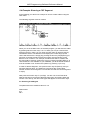
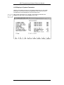
1
Manual
MC5
Programming
Software
Order-No.:VIPA MC5-HB12E
Rev. 00/35
Subject to modifications as required by technical progress.
The information contained in this Manual can be modified without prior notice. VIPA GmbH does not
undertake any responsibility relating to this document. The hardware and software described in this Manual
is supplied subject to a general license agreement. The use and the passing on of software is only admissible
in accordance with the contractual stipulations. Transferring this software or this manual to a magnetic tape,
a diskette or any other medium without the prior written consent of VIPA GmbH - except for personal use shall be deemed an offence.
The software described in this manual is protected by copyright law applicable on an international basis. Any
information which may have become known after the date of print of this manual is included on a file stored
on the enclosed diskette. To read this file - if provided - please insert the VIPA driver diskette #1 into drive
A: and type-in under MS-DOS:
A>TYPE README.TXT
To view the file under Windows® , please use the ,,NOTEPAD"; under OS/2® , please use ,,E".
Manufacturer
© Copyright 2000 VIPA, Gesellschaft für Visualisierung und Prozessautomatisierung mbH
Ohmstraße 4, D-91074 Herzogenaurach,
Tel.: +49 (91 32) 744 -0
Fax.: +49 (91 32) 744-144
EMail: [email protected]
http://www.vipa.de
Hotline:
+49 (91 32) 744-114
VIPA® is a registered trademark of VIPA Gesellschaft fur Visualisierung und Prozeßautomatisierung mbH
MS-DOS® is a registered trademark of Microsoft Corp.
SIMATIC® is a registered trademark of Siemens AG.
NetWare® is a registered trademark of Novell Corp.
IBM-LAN-Server® and OS/2® are registered trademarks of IBM
Subject to modifications as required by technical progress.
MC5 Programming Software Reference Manual
1. INTRODUCTION .......................................................................... 1-1
1.1 MC5 PROGRAMMING SOFTWARE........................................... 1-1
1.2 USER'S MANUAL FOR MC5 PROGRAMMING SOFTWARE .. 1-2
1.3 INTRODUCTION TO THE MS-DOS OPERATING SYSTEM .... 1-2
1.3.1 General.................................................................................... 1-2
1.3.2 Files, File Use ......................................................................... 1-4
1.3.3 Working with ........................................................................... 1-7
1.3.4 MS DOS Commands................................................................ 1-8
1.3.5 Grouping of Files ................................................................... 1-12
2. INSTALLING THE MC5 PROGRAMMING SOFTWARE ..... 2-1
2.1 CONTENTS OF THE MC5 PROGRAMMING SOFTWARE....... 2-1
2.2 SYSTEM REQUIREMENTS......................................................... 2-2
2.3 MAKING A SPARE COPY .......................................................... 2-2
2.4 INSTALLING THE PROGRAM ON THE HARD DISK .............. 2-4
2.5 PROGRAM EXECUTION ............................................................ 2-5
2.6 USING EXTENDED MEMORY ................................................... 2-8
2.7 COMMAND LINE PARAMETERS.............................................. 2-9
3. Blocks ............................................................................................... 3-1
3.1 FILENAMES.................................................................................. 3-1
3.2 BLOCKS ............................................................... ........................ 3-1
3.2.1 Command Blocks ................................................ ........................ 3-1
3.2.1.1 General Information ................................ ........................ 3-1
3.2.1.2 Function Blocks ...................................... ........................ 3-3
3.2.1.3 Segments .......................................................................... 3-5
3.2.1.4 Jump Instructions and Jump Markers .............................. 3-6
3.2.1.5 Peripheral Addressing ...................................................... 3-6
3.2.2 Data Blocks ................................................................................. 3-7
4. HELP SYSTEM............................................................................... 4-1
4.1 CALL UP HELP SCREENS .......................................................... 4-2
4.2 ENTER YOUR OWN HELP TEXTS ............................................ 4-2
5. PROGRAM OPERATION ............................................................. 5-1
5.1 KEYBOARD................................................................................... 5-1
5.2 SCREENS ....................................................................................... 5-2
5.3 ENTRY - WINDOWS..................................................................... 5-2
5.4 CANCEL COMMANDS, QUIT PROGRAM ................................. 5-3
5. PRESET MENUE............................................................................ 6-1
6.1 KEYBORD LAYOUT AND OPERATION ................................... 6-2
6.2 MC5 SPECIFIC SETTINGS .......................................................... 6-2
6.2.1 Preset: Drives FDO, FD1 ........................................................ 6-2
6.2.2 Preset: On-line.......................................................................... 6-3
6.2.3 Preset: Editor............................................................................ 6-4
6.2.4 Preset: Symbolic ....................................................................... 6-6
6.2.5 Preset: Print.............................................................................. 6-8
6.2.6 Preset: Special .......................................................................... 6-10
6.2.7 Preset: Report ........................................................................... 6-11
7. MAIN MENU................................................................................... 7-1
7.1 FUNKTION KEY LAYOUT AND MENU BRANCHING .............. 7-1
7.2 MENUS .......................................................................................... 7-1
Rev. 00/35
VIPA
i
MC5 Programming Software Reference Manual
8. STL EDITOR MENU...................................................................... 8-1
8.1 LOADING AND FUNCTION KEY LAY-OUT LIST .................... 8-1
8.2 FILES, BLOCK EDITING .............................................................. 8-7
8.2.1 Create a new file ..................................................................... 8-7
8.2.2 Editing MC5 Blocks ................................................................ 8-7
8.2.3 Leaving the editor menu.......................................................... 8-8
8.2.4 Allocate other Edit Buffers...................................................... 8-9
8.3 EDITOR FUNCTIONS BY MEANS OF FUNCTION KEYS........ 8-10
8.3.1 Functions: Load a file, remove a file ...................................... 8-10
8.3.2 Functions: Save, new name, compile ...................................... 8-11
8.3.3 Functions: Search, replace, repeat ......................................... 8-12
8.3.4 Function : Mark ...................................................................... 8-13
8.3.5 Block functions (Copy, write, load, delete) ............................ 8-13
8.3.6 Function: Print........................................................................ 8-14
8.3.7 Function: Compile( Compilation of files into PG-format)...... 8-15
8.3.8 Function: Update .................................................................... 8-16
8.3.9 Function: Sym ......................................................................... 8-17
8.3.10 Change to LAD...................................................................... 8-17
8.3.11 Change to CSF ...................................................................... 8-17
9. CSF -CONTROL STATEMENT FLOWCHART ........................ 6-1
9.1 MC5 CSF NORMENCLATURE..................................................... 9-1
9.1.1 The CSF-Editor ......................................................................... 9-3
9.1.2 Create new files........................................................................ 9-3
9.1.3 Editing CSF-Blocks.................................................................. 9-3
9.1.3.1 Block level ............................................................................. 9-3
9.1.3.2 Segment level......................................................................... 9-4
9.1.3.3 Gate level .............................................................................. 9-5
9.1.4 Leaving the CSF-editor............................................................ 9-6
9.1.5 Assigning further CSF-Editor buffers ...................................... 9-7
9.2 CSF-EDITOR FUNCT. USING FUNCTION KEYS ON BLOCK . 9-7
9.2.1 Function: Load file.................................................................... 9-7
9.2.2 Function: Save file ................................................................... 9-8
9.2.3 Function: Segment Number...................................................... 9-9
9.2.4 Function: Insert before Segment .............................................. 9-9
9.2.5 Function: Append behind Segment .......................................... 9-9
9.2.6 Function: Edit Segment............................................................ 9-9
9.2.7 Function: Delete Segment ........................................................ 9-9
9.2.8 Function: Print......................................................................... 9-9
9.2.9 More functions ......................................................................... 9-10
9.3 CSF-Editor FUNCTIONS ON SEGMENT LEVEL ........................ 9-11
9.3.1 Function Horizontal extend ................................................... 9-11
9.3.2 Function Vertical extend ........................................................ 9-11
9.3.3 Function Switch ..................................................................... 9-11
9.3.4 Function Segment comment ................................................... 9-12
9.3.5 Function Delete...................................................................... 9-12
9.3.6 Functions Ready and Abort...................................................... 9-12
9.3.7 More junctions ......................................................................... 9-12
9.4 EXAMPLE: entering A CSF SEGMENT ........................................ 9-13
9.5 SYMBOLS IN CSF.......................................................................... 9-16
10. LAD-LADDER LOGIC ................................................................ 10-1
10.1 MC5 LAD NORMENCLATURE ................................................. 10-2
10.1.1 The LAD-Editor ....................................................................... 10-3
10.1.2 Create new files ...................................................................... 10-3
10.1.3 Editing LAD Blocks and Segments .......................................... 10-3
10.1.3.1 Block level....................................................................... 10-3
10.1.3.2 Segment level .................................................................. 10-4
10.1.3.3 Contact level ................................................................... 10-6
10.1.3.4 Branch level.................................................................... 10-7
ii
VIPA
Rev. 00/35
MC5 Programming Software Reference Manual
10.1.4 Leaving the LAD-editor....................................................... 10-8
10.1.5 Assigning further LAD-Editor buffers ................................. 10-9
10.2 LAD-EDITOR FUNCTIONS USING FUNCTION KEYS ON BL. ............. 10-10
10.2.1 Function: Load file.............................................................. 10-10
10.2.2 Function: Save file .............................................................. 10-11
10.2.3 Function: Segment Number................................................. 10-11
10.2.4 Function: Insert before Segment ......................................... 10-11
10.2.5 Function: Append behind Segment...................................... 10-11
10.2.6 Function: Edit Segment ....................................................... 10-11
10.2.7 Function: Delete Segment ................................................... 10-12
10.2.8 Function: Print.................................................................... 10-12
10.2.9 More functions..................................................................... 10-12
10.3 LAD-EDITOR FUNCTIONS AT SEGMENT LEVEL............... 10-13
10.3.1 Function: Insert /Super Insert .............................................. 10-13
10.3.2 Function: Append / Super Append ....................................... 10-13
10.3.3 Function: New Input ............................................................ 10-13
10.3.4 Function: Switch .................................................................. 10-13
10.3.5 Function: Branch ................................................................. 10-13
10.3.6 Function: Segment Comment ............................................... 10-14
10.3.7 Function: Delete................................................................... 10-14
10.3.8 Function: Ready ................................................................... 10-14
10.4 LAD-ED1TOR FUNCTIONS AT CONTACT LEVEL.............. 10-14
10.4.1 Function: RETURN / change Contact or Contact Symbol ... 10-14
10.5 LAD-EDITOR FUNCTIONS AT BRANCH LEVEL................. 10-15
10.5.1 Function: Extend Up ............................................................ 10-15
10.5.2 Function: Extend Down ....................................................... 10-15
10.5.3 Function: New...................................................................... 10-15
10.6 EXAMPLE: ENTERING A LAD SEGMENT............................ 10-15
11. TRANSFER MENU ...................................................................... 11-1
11.1 ACTIVATION AND FUNCTION KEY LAY-OUT ................... 11-1
11.2 S5D-FILE TRANSFER................................................................ 11-1
11.2.1 S5D-File Menu ..................................................................... 11-1
11.3 SYMBOL-FILE TRANSFER/CONVERTION............................ 11-2
11.3.1 SEQ-File Menu..................................................................... 11-2
11.4 COPY PG-DISKETTES............................................................... 11-2
11.5 TRANSFERING BLOCKS.......................................................... 11-3
11.5.1 General .................................................................................. 11-3
11.5.2 Entry window, operation and messages................................. 11-3
11.5.3 Examples of the function "Transfer Block" ........................... 11-4
12. DELETE MENU............................................................................ 12-1
12.1 ACTIVATION AND FUNCTION KEY LAY-OUT.................... 12-1
12.2 INITIALIZING THE PROGRAMMABLE CONTROLER.......... 12-1
12.3 DELETE PG675-DISKETTES *)................................................. 12-2
12.4 DELETE PG685/635 PROGRAMM FILES *) ........................... 12-2
12.5 DELETE BLOCKS..............................................................12-3
12.6 DELETE EEPROM............................................................12-4
13. SPECIAL MENU.................................................................13-1
13.1 ACTIVATION AND FUNCTION KEYLAY-OUT ..................... 13-1
13.2 START AND STOP THE PC....................................................... 13-1
13.3 COMPRESS MEMORY .............................................................. 13-2
13.4 FORMATTING ............................................................................ 13-3
Rev. 00/35
VIPA
iii
MC5 Programming Software Reference Manual
14. INFORMATION MENU .............................................................. 14-1
14.1 ACTIVATION AND FUNCTION KEY LAY-OUT.................... 14-1
14.2 CROSS REFERENCE FUNCTIONS........................................... 14-1
14.2.1 Cross Reference List.............................................................. 14-2
14.2.2 I/Q/F-Plan............................................................................. 14-3
14.3 DIRECTORY FUNCTION .......................................................... 14-6
14.3.1 General.................................................................................. 14-6
14.3.2 Function "Dir" in the Info Menu........................................... 14-8
14.3.3 Directory function with entering file names ......................... 14-9
14.4 FUNCTION DOC: PRINT BLOCKS ......................................... 14-9
14.5 INFORMATION ON THE MEMORY SIZE .............................. 14-10
14.6 DISPLAY OF THE INTERRUPT STACK .................................. 14-11
14.7 DISPLAY OF BLOCK STACK ................................................... 14-12
14.8 DISPLAY OF SYSTEM PARAMETERS.................................... 14-13
15. TEST MENU........................................................................15-1
15.1 ACTIVATION AND FUNCTION KEY LAY-OUT..................... 15-1
15.2 CONTROL VARIABLES, STATUS VARIABLES...................... 15-1
15.2.1 Operation and function key lay-out....................................... 15-1
15.2.2 Screen displays and operation .............................................. 15-2
15.2.3 Creating and loading a list of variables ............................... 15-4
15.2.4 Start Status scan.................................................................... 15-6
15.3 CONTROLLING OUTPUTS ....................................................... 15-8
15.3.1 Operation and function key lay-out....................................... 15-8
15.3.2 Screen displays and operation .............................................. 15-8
15.3.3 Creating and loading an Output Control list........................ 15-10
15.3.4 Start Control ......................................................................... 15-11
15.4 STATUS BLOCK.......................................................................... 15-12
15.4.1 Activation and function key lay-out....................................... 15-12
15.4.2 Screen display and operation................................................ 15-13
15.4.3 Preparing the output status................................................... 15-15
15.4.4 Function "Status" .................................................................. 15-15
15.5 FUNCTION STATUS IN CSF/LAD ............................................. 15-16
16. ADDRESS MENU ......................................................................... 16-1
16.1 ACTIVATION AND FUNCTION KEY LAY-OUT..................... 16-1
16.2 SCREEN DISPLAY AND HANDLING....................................... 16-2
16.3 SELECT MEMORY RANGE ....................................................... 16-4
16.4 CHANGE VALUES ..................................................................... 16-4
16.4.1 Changes by using the keyboard (Edit) ................................... 16-4
16.4.2 Fill memory range.................................................................. 16-5
16.4.3 Recalling and saving changes................................................ 16-6
16.5 MARKING A MEMORY RANGE ............................................... 16-7
16.6 PRINT MEMORY......................................................................... 16-8
17. COMPILING BLOCKS .....................................................17-1
17.1 GENERAL .................................................................................... 17-1
17.2 RULES FOR SAVING FILES ...................................................... 17-1
17.2.1 Saving to FD or EPROM/EEPROM ...................................... 17-1
17.2.2 leading from FD or EPROM/EEPROM................................. 17-2
17.3 PASS 1 /PASS 2............................................................................ 17-2
18. PG-DRIVES, PG-DISKETTES.................................................... 18-1
19. SYMBOLIC ADDRESSING ........................................................ 19-1
20. WORKING WITH EPROM/EEPROM MODULES ................ 20-1
iiii
VIPA
Rev. 00/35
MC5 Programming Software Reference Manual
21. LANGUAGE TRANSLATION .........................................21-1
21.1 TRANSLATING BLOCKS ........................................................ 21-1
21.2 TRANSLATING THE SYMBOL-FILE ..................................... 21-1
22. ADDITIONAL MC5 FACILITY PROGRAMS .............22-1
22.1 INDEXING VERYLARGE SYMBOL FILES .......................... 22-1
22.2 REMOVING DOUBLE SPACES IN SYMBOL NAMES ......... 22-1
Rev. 00/35
VIPA
iiiii
MC5 Programming Software Reference Manual
iiiiii
VIPA
Rev. 00/35
MC5 Programming Software Reference Manual
1. Introduction
1.1 Programming Software MC5
The Programming Software MC5 is a development tool to write, fast and
easily, STEPâ5-programs in STL or CSF for Siemens Programmable
Controllers (PC's). The complete version of Programming Software MC5
covers STEPâ5 functions offered by the Siemens programming terminal
"PG685".
With the Programming Software STEPâ5 from Siemens, programs can be
developed on all IBM-AT or compatible computers that run under
MS-DOS/PC-DOS. These files can be saved in ASCII-format on the hard
disk or in any of the following formats: PG675, PG635, PG685 (see chapter
2 for system hardware requirements). Files created with these PG's can
easily be edited using the Programming Software MC5.
The Programming Software version 2.xx and higher does not run
on IBM-XT personal computers or compatibles.
It should not be difficult for a PLC programmer to change over to MC5Programming Software. An extensive help system may be called up from any
place within the menu structure. A thorough knowledge of the MS-DOS/PCDOS operating system is not required, but could be helpful. Some MS-DOS
basic commands are described in chapter 1.3.
While working with the MC5-Programming Software, you will find that it is
very user friendly. Some improvements, compared to the methods used up
to now, are listed below:
• All Blocks of a STEPâ5 program from Siemens (OB, PB, FB, FX, DB, DX,
etc.) can be made available as ASCII-files on a DOS-diskette).
• There are extensive comment and documentation facilities i.e.:
comment lines or longer explanatory texts can be added or inserted in
between instruction lines (in PG-terms known as "Documentation Blocks").
• There can be up to 16 files at the same time in separate memory areas
ready to work with and to copy any program part.
• Excellent editing facilities having several functions (such as: Search
and/or Replace, Copy, Move, Delete, etc.) are available for program
development.
• In order to explain separate functions, the User Configurable Help System
may be called up at any time within the menu structure. Your own text may
also be added.
• While editing, many additional functions can be activated, e.g. print the
program, shell to MS-DOS command level and with a quick return to the
edit functions.
• Colors on all screen items may be changed to meet individual taste or
requirements.
Rev. 00/35
VIPA
1-1
PLEASE NOTE:
A general
knowledge of
STEPâ5
programming from
SIEMENS is
required when
working with
MC5-Programming
Software. Training
is available on
request.
MC5 Programming Software Reference Manual
1.2 User's Manual for MC5-Programming Software
The User's Manual describes how to work with the MC5-Programming
Software. In order to find easier certain parts of the text, the pages have been
divided into three columns as follows:
Left column
Text part
Right column
Symbols
Keywords
Text
Instructions
Remarks
As an additional help for orientation, the current chapter number is printed on
every page.
Explanation of Symbols used:
Symbol for the F1 key, meaning: "Press Function Key F1". Symbol for the
ENTER key (RETURN key), meaning: "Press ENTER key".
These two symbols together mean: "Press the ALT and F1 keys
simultaneously".
Simultaneously means: first press the switch key (e.g.: CTRL, ALT or
SHIFT) and hold it down, then toggle the second key and release the
switch key.
Symbol for the menu dependent entry window.
1.3 Introduction to the MS-DOS Operating System.
1.3.1 General
The MS-DOS Operating System controls the execution of application
programs and hardware functions such as disk instructions and supports
user utilities.
Although PLC programmers do not need an extensive knowledge of MSDOS, some basic commands are explained on the following pages in order
to help them with the MC5-Programming Software.
Files and their use, as well as the structure of MS-DOS commands
(command syntax), are explained in this chapter. Some MS-DOS
commands, together with a short description, are listed in chapter 1.3.4.
These commands are only executed after ENTER has been pressed. A few
characteristics concerning the execution of MS-DOS commands are
explained in chapter 1.3.5.
MS-DOS commands can only be executed from the MS-DOS command level
when the so-called prompt is displayed. A typical prompt consists of a
character representing the drive identification (in this case hard disk C), the
character" »" and the blinking cursor (here the underscore).
C»
1-2
VIPA
Rev. 00/35
MC5 Programming Software Reference Manual
When entering MS-DOS commands without the drive identification, the
operating system will only look for the necessary files and programs in the
current directory of the current drive.
In order to change drives, enter the desired drive identification (character and
colon (:)).
Example: To change to drive A:
Type A:
and press ENTER
The new prompt appears:
A»_
In general, any of the following drive identifications may be used:
A: Diskette drive A or diskette in drive A
B:
Diskette drive B or diskette in drive B
C:
Hard disk C or hard disk partition C
D:
Hard disk D or hard disk partition D
MS-DOS offers the possibility to call up files with abbreviated commands.
The following commands appear in the MS-DOS manual:
PATH command
This command instructs the operating system to search for a file on the
specified drives and in the required directories. Enter the search path behind
the command PATH.
Once this command is executed, the operating system will not only look for
the specified file in the current directory, but also on every drive and/or in any
directory included in the search path. Multiple paths may be specified, but
have to be separated by a semicolon.
PROMPT command
With this command, the appearance of the prompt can be changed. A
meaningful change would be to show the current drive identification and
directory before the blinking cursor.
Both commands are briefly explained in chapter 1.3.5. of this manual
(keyword: AUTOEXEC.BAT).
Rev. 00/35
VIPA
1-3
MC5 Programming Software Reference Manual
1.3.2 Files, File Use
All texts entered (e.g. SPS-files) are stored by MS-DOS in files which have
been created previously. These files can be arranged and saved orderly in
directories.
While working with the MC5-Development Software, the user will be
prompted to enter a filename. The program will then automatically create the
file.
On MS-DOS level, a user file can be created by using the MS-DOS
command COPY CON and by entering a filename. Creating a so-called
batch file" (storing a sequence of commands) with a tile extension ".bat" is
very useful in practice as it simplifies the startup procedure. The creation of a
".bat" file is explained in chapter 1.3.5.
The user makes up his own filenames. Within directories only unique
filenames can be used. A filename contains no more than eight
alphanumeric characters. No spaces are allowed. When entering
commands and/or filenames, no distinction is necessary between either
capitals or small characters. The operating system will accept either, e.g.
PRO_1234orpro_1234.
When selecting a group of files (e.g. all texts, all programs for plant B4, etc.),
it is recommended to use filename extensions. The extensions are
connected to the filenames by the character period (.) and may contain no
more than three characters, (e.g.: PRO_12.B4).
Some filenames are not to be used, as these names are used by the
operating system itself. Device names like AUX, CLOCKS, COM, CON,
KEYBD$, LPT, LST, NULL, PRN and SCRN$ are being used by the system.
Please check the MS-DOS manual for a complete list.
The file extensions .SYS, .EXE, .BAT, .COM are used by MS-DOS. These
tile extensions should only be used when creating files with purposes similar
to the ones of MS-DOS. For creating a batch file with the extension .BAT,
see chapter 1.3.5.
File Use
The computer offers an organization system for storing tiles (root directory,
directories and subdirectories), which branches like a tree. These files can
be used in the same way as files in a normal office tiling system. The root
directory is always designated by the back slash (" \").
Directories, subdirectories and tiles are created by the user. The following
scheme gives an overview of the way files might be arranged:
1-4
VIPA
Rev. 00/35
MC5 Programming Software Reference Manual
File Organization
Since the user is able to create directories and subdirectories, a
personalized organization structure may be set up. It could be organized
on the hard disk as follows:
Root directory C
System files
MC5
Project
OB 21
FB 100
DB 11
XYZ123
MC5
files
ZXY321
File 1.t
filelo.txt
ERIC
MILLER
PRO 11.TXT
files(s)
The examples used in this manual relate to such a directory structure.
If files are to be saved on diskette, it is better not to create directories
and/or subdirectories. The file structure on the diskettes could then be
as follows:
Rev. 00/35
VIPA
1-5
MC5 Programming Software Reference Manual
First diskette in drive A:
Second diskette in drive A:
1-6
VIPA
Rev. 00/35
MC5 Programming Software Reference Manual
1.3.3 Working with
With the help of three simple MS-DOS commands, directories can be
manipulated. Each command is described below (the general command
structure (command syntax is explained in chapter 1.3.4):
Make a new directory with:
MD or MKDIR Meaning:
make directory
Change to another directory with:
CDorCHDIR Meaning: change
directory
Show the contents of the current directory:
DIR Meaning: directory
Select always a directory name, which indicates the purpose or usage of the
directory contents. A directory name contains no more than eight characters.
No spaces may be used.
Please refer to the operating system manual of the computer for the use of
special characters in directory names.
Examples:
In order to install the MC5-Programming Software, create a subdirectory
(with the name MC5) in the current root directory on drive C:
Command line:
MC5
C_ Command:
MD
Command line:
C_
Command:
DIR
The contents of the root directory of drive C will be displayed on the
screen. The name of the MC5 directory will also be shown.
Command line:
MC5
C_ Command:
Command line:
CD
C: MC5 Command:
CD
The screen displays the current directory:
C:\MC5
Command line:
C:\MC5
In order to return to the parent directory, enter two periods (..) behind the
DOS command CD.
Command
Rev. 00/35
CD..
VIPA
1-7
MC5 Programming Software Reference Manual
In order to return immediately to the root directory regardless of the current
directory, enter a back slash (" \") behind the command CD.
Command CD \
The current directory is again the root directory of drive C:
Command line:
C:_
1.3.4 MS-DOS Commands
MS-DOS commands may be entered in capital or small letters from MS-DOS
command level (prompt at the beginning of the line). Wrong characters can
be erased with the BACKSPACE
Commands will be confirmed and executed after RETURN has been
pressed.
On the following pages some commands are briefly explained, when
displaying these commands, the following identifications are used for
recognition:
Bold Printing:
Bold printing will be used for inputs, commands and special characters, such
as colon (:) and backslash (\).
CAPITALS (UPPER CASE):
Capitals are used for names of drives and directories.
Here, use the required target identifications together with the following:
DR
Drive (A, B, C,...)
DIRNAME
Directory Name
FILENAME Name of File
MS-DOS commands are structured as follows (command structure):
Command Parameter Below follows the copy
command as an example:
Command
Parameteri Parameter2 (Source)
(Target)
In example 1, a file called 'fb100' (saved in the directory PR0111 on hard
disk C) is being copied to a diskette in drive A:
Example 1:
COPY C:\PR0111\fb100A:
1-8
VIPA
Rev. 00/46
MC5 Programming Software Reference Manual
Now the diskette in drive A contains the file fb100.
(The contents of the diskette in drive A can be displayed with the MS-DOS
command DIR A:).
Example 2:
On the diskette in drive A, a directory TEXT10 has been created with the
MS-DOS command MD (or MKDIR). Now the file 'fb100' has to be copied to
the directory TEXT10.
COPY C:\PR0111\fb100A:\TEXT10
File 'fb100' may now be found in directory TEXT100 on the diskette in drive
A.
Try again to display the contents of the diskette in drive A (use MS-DOS
command DIR A:\TEXT10).
Example 3:
The filename 'fb100' can also be "changed" to 'fb11' by using the COPY
command:
COPY CAPR0111\fb100 A:\TEXT10\fb11
File 'fb11' may be found in directory TEXT10 on the diskette in drive A. Use
the MS-DOS command DIR A:\TEXT10 to display its contents .
The contents of files 'fb100' and "fb11' are identical. This means that Block
FB11 contains the same Block identification (BLOCK#FB100) in the first line
and, if used, will create a transfer error.
List of some MS-DOS Commands
Change directory
CD or CHDIR
changes the current drive and the current directory names.
CD DIRNAME or CHDIR DIRNAME
Changes from the current directory to directory DIRNAME.
CD.. or CHDIR..
Changes from the current directory to the parent directory.
COPY
COPY DR1:\DIRNAMBfilename
DR2:\DIRNAMBfilename
copies the file "filename" from the "source" to the "target".
i.e.: from drive DR1, directory DIRNAME to drive DR2, directory
DIRNAME.
Rev. 00/46
VIPA
1-9
MC5 Programming Software Reference Manual
DELETE
DEL filename
Deletes the file "filename" in the current directory without prompting for
confirmation.
DR:\DIRNAME/filename
Deletes the file "filename" in the directory DIRNAME of drive DR:, without
asking for verification.
DEL DIRNAME
Deletes all files in directory DIRNAME . With this command the computer will
ask for verification and expects confirmation for further execution of this
command (Enter "Y" for Yes, "N" for No and confirm by pressing RETURN).
The empty directory will remain on disk, but may be deleted with the MSDOS command RD (or RMDIR).
DISPLAY DIRECTORY (DIR)
All filenames and directory names within the current directory will belisted.
The file size (in bytes) and the date/time, of the last time it was saved, is
shown as well.
DIR DIR filename
Displays the file with this filename. The file size (in bytes) and the
date/time, of the last time it was saved, is shown as well.
DIR DRADIRNAME
Displays all filenames and directory names within the current directory. The
file size (in bytes) and the date/time, of the last time it was saved, is shown
as well.
DIR DR:\DIRNAME /P
Displays all filenames and directory names of the directory DIRNAME of
Drive DR:per "page" (screen size). To view the next screen (page), press any
key.
DIR DR:\DIRNAME /W
Displays all filenames and directory names of the directory DIRNAME in four
columns. The file size and the date/time are not shown.
The switches /P and /W are options.
1-10
VIPA
Rev. 00/35
MC5 Programming Software Reference Manual
Copy diskettes with MS-DOS command DISKCOPY
DISKCOPY DR1: DR2:
Copies the contents of the entire diskette in drive DR1 to a diskette in drive
DR2. Already existing files on the diskette in drive DR2 will be erased. (In
case a new MS-DOS version is used, the system will format your diskette
while copying).
Format diskettes with MS-DOS command FORMAT
FORMAT DR:
Formats a diskette in drive DR:.
FORMAT DR: /v
Formats a diskette in drive DR:, with a provision to enter a volume label.
FORMAT DR: /4
Formats a 360 Kbyte diskette (in drive DR: on two sides), when placed in a
1,2 Mbyte drive of an AT or 386.The switches /v and /4 are options.
Create a directory with MS-DOS command MD or MKDIR
MD DIRNAME MKDIR
DIRNAME
Makes (creates) a directory with the name DIRNAME in the current
directory.
Change filename with MS-DOS command PEN (rename)
PEN filename.old filename.new
Renames a file, e.g. changes the old name to a new name. lf the name
already exists, an error message will appear.
Remove a directory with MS-DOS command RD or RMDIR
RD DIRNAME RMDIR
DIRNAME
Removes the directory with the name DIRNAME. The directory must be
empty before removing it. See DEL to delete files .
For other commands and examples. please refer to the MS-DOS manual.
Rev. 00/35
VIPA
1-11
MC5 Programming Software Reference Manual
1.3.5 Grouping of Files
Wildcards in filenames:
A wildcard is a character, which can replace one or more characters in a
filename. The use of the wildcards Asterisk *) and Question mark (?) are
explained below. For more specific information, please refer to the MS-DOS
manual.
Examples where the wildcard " *" (Asterisk) is used:
Suppose that all text files have the extension .TXT. In order to know which
files with this extension are in the current directory, enter the following
command:
DIR *.TXT
All tiles with the extension .TXT in the current directory will be displayed.
If all files in the directory PRO_11 on the hard disk C are to be copied onto a
diskette in drive A, enter the following command:
COPY C:\PRO_11\*.* A:
The wildcards *.* represent all files in the directory C:\PRO_11.
Examples where the wildcard "?" (Question mark) is used:
Several files have been created with names like 'fb10', 'fb20', 'fb30', etc.. In
order to find these files in the current directory, enter the following
command:
DIR fb?0
All filenames starting with the characters 'fb' and followed by any character
and the zero will be displayed on the screen.
The wildcard "?" can be used more than once in a filename, e.g. 'fb??'. Both
wildcards can also be used in conjunction:
DIR fb??.*
In other words, and according to the example above, all files from the current
directory will be displayed when they meet the following requirements:
− "f" and "b" are the initial characters in the filename,
− one or two other characters, which can replace the question
marks,
− follow the initial characters as part of the filename and
any or no file extension
1-12
VIPA
Rev. 00/35
MC5 Programming Software Reference Manual
For example, filename 'fb100' does not comply with these conditions,
because in this case "f" and "b" are followed by three characters (100). This
does not agree with the two question marks in the command. Program file
AUTOEXEC.BAT
After the computer is switched on, MS-DOS will, first of all, look for the
AUTOEXEC.BAT-file.
In this so called "batch file" (similar to batch processing), commands can
be entered. These will be executed every time the computer is switched
on.
With the help of the MS-DOS command COPY CON filename (copy directly
from the console), such a batch file can be created. Please be aware of the
following:
− Entries can only be edited on the current line. Once ENTER
RETURN) has been pressed, no more changes can be made !!
− Press CTRL and the Z-key simultaneously to terminate the file
creation.
− Press ENTER to save the newly created file. If the file already
exists, the old file will be overwritten by the new file. The contents
of the old file will be lost!!
When creating a new AUTOEXEC.BAT, the following command lines could
be useful:
ECHO OFF
This command instructs MS-DOS not to display the commands of the
AUTOEXEC.BAT file on the screen as they are executed.
PROMPT $P$G
This command sets the command prompt to display the current drive and
path followed by the greater than sign (»):
DR:\DIRNAMBDIRNAME»_
e.g.: C:\ABT_12\ERIC»_
i.e.: the current drive and current directories will be shown before the
blinking prompt.
KEYB UK or KEYB US
This command changes the keyboard layout to the English (English
keyboard driver) or to the American version (on other systems, a different
command may be required). PIease refer to the DOS-manual.
PATH
Normally, when searching for a file, the system searches in the current
directory only. With the PATH command, the operating system is ordered to
search for the file in other directories and subdirectories (only the ones
specified in this path command) as well.
Rev. 00/35
VIPA
1-13
MC5 Programming Software Reference Manual
PATH= C:\;C:\DOS;C:\MC5;
The operating system will first search the specified file in the root directory of
drive C, then in the DOS directory and finally in the subdirectory MC5.
The search paths must be separated by a semicolon (;) CD
DIRNAMBDIRNAME
Instead of the directory called DIRNAME, enter the name of the directory
where the files are to be saved. MS-DOS will change automatically to this
directory when the MC5 software is started.
MC5
The program MC5.EXE will automatically be executed. The main menu, with
the opening screen, will be displayed.
Example to create an AUTOEXEC.BAT file:
First, return to the root directory by entering:
CD\
Command line:
C_
Start creation:
COPY CON AUTOEXEC.BAT
Command line: _ (blinking prompt)
Enter:
©ECHO OFF
PROMPT$P$G KEYB
UK
PATH=C\;CDOS;C\MC5
CDVDIRNAMBDIRNAME
MC5
In order to end the input, press CTRL and the Z-key simultaneously.
Displayed on the screen by: ^Z
Confirm with RETURN (or ENTER).
1-14
VIPA
Rev. 00/35
MC5 Programming Software Reference Manual
This ends the creation of the batch file. Every time you start the computer,
this batch file will be executed.
Rev. 00/35
VIPA
1-15
MC5 Programming Software Reference Manual
1-16
VIPA
Rev. 00/35
MC5 Programming Software Reference Manual
2. Installing the MC5 Programming Software
2.1 Contents of the MC5 Programming Software
Requirements:
− MC5 Card or Off-line or Serial Dongle
− Program diskettes (5,25" or 3,5")
− Demo programs
− User manual
The MC5 Card
The MC5 card is installed in an empty slot of the computer. There will be no
difficulty to insert the card, but please do pay attention to the manufacturer's
instructions (see the instructions manual of your PC). If no explicit limitations
are mentioned, a professional installation of the MC5 card will not void the
guarantee given by the computer manufacturer.
Check the settings of the DIP-switches before installing the MC5 card,.
The default configuration of MC5 is set to communicate with the interface
card via base address 100h (corresponding to the DIP-switch setting
mentioned before). The card has 8 alternative (100h-107h) I/O addresses.
To change the base address, run the program PATCHxxx.COM. The
program will show the new DIP-switch setting for the interface card and will
reconfigure the MC5 software. Since this program is unique for every version
of MC5, the symbol "xxx" indicates the appropriate version, e.g. 311 is
version 3.11.
To run PATCH with the help text in English, add" /e" to the command.
Example:
Command:
Rev. 00/35
patch /e
VIPA
2-1
MC5 Programming Software Reference Manual
2.2 System Requirements
MC5 Programming Software can be used on many different computers.
However, for best results with the MC5 Programming Software, the
system should meet certain minimum requirements:
Computer
− IBM-AT or compatible
− Minimum Memory of 640 KByte
− Appropriate Video Interface, e.g.:
− Monochrome Graphic Adapter Colour Graphic Adapter
Enhanced Graphic Adapter
− Diskette drives 5,25" and/or 3,5" (see chapter 18)
720 Kb for PG635 diskettes
1,2 Mb for PG685 diskettes
360 Kb for PG675 diskettes
Operating System Requirements
− MS-DOS version 3.31 or higher
The presentation can be either in colour or monochrome (depending on the
type of monitor).
A hard disk with at least 2.5 Mb free storage capacity. (A
hard disk with cache is highly recommended!)
2.3 Making a Spare Copy
Before installing the MC5 Programming Software on your hard disk, please
make a copy of the original diskettes.
Preparations
Protect the original diskettes with the write protect tab and keep a suitable
MS-DOS formatted diskette close at hand. ln order to start the copy
procedure, use the following MS-DOS command and press RETURN to
confirm:
DISKCOPY DR: DR:
Copy Procedure for a Computer with Two Identical Diskette Drives:
DISKCOPY A: B:
The MS-DOS operating system will display the following message:
2-2
VIPA
Rev. 00/35
MC5 Programming Software Reference Manual
Insert SOURCE diskette in drive A:
Insert TARGET diskette in drive B:
Strike a key when ready ...
Follow these instructions. The contents of the original diskette (SOURCE) will
be copied to the spare diskette (TARGET).
The operation has come to an end when the operating system displays the
following message:
Copy any other diskettes (Y/N)?
To end the copy procedure, press N.
Copy Procedure for a Computer with only One Diskette Drive
DISKCOPY A: A:
The MS-DOS operating system will display the following message:
Insert SOURCE diskette in drive A:
Strike a key when ready ...
Follow the instructions. The contents of the original diskette will be copied into
the memory of your computer. The first part of the operation has come to an
end when the operating system displays the following message:
Insert TARGET diskette in drive A:
Strike a key when ready ...
Follow the instructions. The contents of the original diskette (SOURCE) will be
copied to the spare diskette (TARGET). If the amount of memory of the
computer is insufficient, this step will have to be repeated.
The operation has come to an end when the operating system displays the
following message:
Copy any other diskettes (Y/N)?
Press N to end the copy procedure.
Rev. 00/35
VIPA
2-3
MC5 Programming Software Reference Manual
2.4 Installing the Program on the Hard Disk
Before working with MC5, it must be installed on the hard disk. It is not possible
to run the program from diskette.
In order to install the MC5 Programming Software on the hard disk, run the
installation program INSTALXX.EXE on the MC5 diskette. Where XX can be
replaced by EN for international (English), NL for Dutch or D for German
installation
By answering the questions, the MC5 installation program will install the
software and will help to configure the system for optimal performance.
Example:
The program diskette has been inserted in drive A.
Enter one of the following commands and confirm this by pressing
RETURN:
A:
INSTALEN
INSTALNL
INSTALD
OR
OR
After a brief delay, the next screen will be displayed. The symbol "x.xx"
indicates the revision of the software:
MC5
Version x.xx
2-4
VIPA
Rev. 00/35
MC5 Programming Software Reference Manual
2.5 Program Execution
After installation of the MC5 Programming Software, the program can
be run using some MS-DOS commands. The following example is based
on PG working experience.
PLC: Several diskettes for one Project.
Expert PG675/685 Programmers are familiar with procedures for large
projects. They know how important it is to maintain programs structured
clearly and efficiently. It is customary to keep PLC-programs on several
diskettes. Use a new set of diskettes for each new project.
PLC:
Several
diskettes
for one
projekt
Such a set may contain:
− program diskettes for automatic and manual control diskettes
− diskettes for data handling in the PLC
− a copy of the Programmable Controller.
The programmer then uses only the work diskette, which contains only the
files currently required.
Edited programs are copied to the respective project diskettes. In fact, all
programs are stored in several "files".
Example:
A project is known by the name of FIRM and consists of the following
diskettes:
− copy of the programmable controller
− transportation,
− material flow,
− RFZ,
− network-master
− network-slave
− a work diskette.
This procedure can also be applied advantageously when working with MC5
that is
installed on a hard disk and uses the MS-DOS operating system (improving
speed and efficiency). Instead of the set of diskettes, create a filing system
on the hard disk - direc
tories and subdirectories -(see also chapter 1.3.2). It will only take a few MSDOS commands. Remember, directory and subdirectory names in DOS
should not contain
more than eight characters. Quotation marks and some other characters are
not allowed.
Rev. 00/35
VIPA
2-5
MC5:
Several
directories
on the hard
disk for one
projekt
MC5 Programming Software Reference Manual
Example:
The project is stored in a directory named FIRM, in which the following
subdirectories have been created: PCABZUG, FT-TECH, MAT-FLOOD, RFZ
and NETWORK. The subdirectory "network" contains the subdirectories NWMAST and NW-SLAVE. The current working directory contains the name
CURRENT.
An appropriate search path must be specified in the PATH command to be
able to work from every directory with the MC5 Programming Software. This
search path directs the system to the directory where the MC5 Programming
Software is installed. In other words, the system is told where the program is
to be found.
PATH
command
The existing path is displayed at the prompt. The MS-DOS command PATH
can be used now. Enter immediately after the command the required path
name and confirm by pressing RETURN. The following example could apply:
C:PATH
PATH=C:\DOS;
If the MC5 software is in the directory "MC5" on the hard disk, "C:\MC5;" will
be added to the PATH command. Confirm by pressing RETURN:
C:PATH=C:\DOS;C:\MC5
If anything is added to the existing path by using the path command, the path
will only remain valid until a new PATH command is executed, until a ".BAT"
file is called up or until the computer is switched off.
Add the line above to the AUTOEXEC.BAT instead of entering this command
every time (see chapter 1.3.5.). This file will be executed at every new start of
the computer (e.g. the function of OB20 and/or OB22 in the programmable
controller). The command could be as follows:
PATH=C:\;C:\SYSTEM\DOS\;C:\MC5;
After entering the search path, create all subdirectories in the MC5 directory.
To create a directory with the name FIRM, use the command MD or MKDIR
(make (subdirectory, see chapter 1.3.4). Then, enter the following command
and confirm by pressing RETURN:
MD\FlRM
Now change to subdirectory FIRM by using the command CD or CHDIR
(change directory, see chapter 1.3.4):
CD\FIRM
Create the following tree (structure) of subdirectories by using the
command MD:
2-6
VIPA
Rev. 00/35
MC5 Programming Software Reference Manual
For running the software from the sub-directory NW-MASTER , change to
this directory by using the following command:
CD\FI RM\N ETWORK\NW-MASTER
Now, run the MC5 Programming Software by entering the program name
"MC5" and confirm by pressing RETURN.
MC5
The initial screen of the MC5 Programming Software will then be
displayed and the system is ready for use.
Rev. 00/35
VIPA
2-7
MC5 Programming Software Reference Manual
2.6 Using extended memory
When your computer is equipped with extended memory configured as XMS
memory, you can activate MC5 to use this memory. Using XMS allows you to
handle very large Symbols files and large Blocks. However, the use of XMS
memory may marginally slow-down several functions of MC5. This means
that if you do not realy need XMS functionality to edit large files you are
advised to use conventional memory. To configure extended memory as
XMS memory you install the driver HIMEM.SYS (or HIMEM.EXE) in your
CONFIG.SYS file. In general you need to add the following line to your
CONFIG.SYS:
DEVICE=C:\DOS\HIMEM.SYS
HIMEM.SYS is available from MS-DOS 5.0.1
XMS use can be activated in two ways:
using the Command-line parameter '/X' at start-up of MC5
(please refer to chapter 2.7).
by configuration in the Preset after which the Preset should be saved and
MC5 should be re-started (please refer to chapter 6.2.6).
If XMS memory is activated the Function bar of the Ctrl-key in the Main
menu will contain the option F8 XMS. Pressing Ctrl+F8 will display the
XMS-lnformation window, giving you information on the amount of XMS
memory available and in use.
2-8
VIPA
Rev. 00/35
MC5 Programming Software Reference Manual
2.7 Command Line Parameters
When starting up the MC5 Programming Software, use the Command Line
Parameters to define certain user configurations of the MC5 Software. The
available options are listed below:
D:\MC5\PILOT1\mc5 /h
Description:
mc5 {[options]} [«filename»]
Parameters:
/H
/D
/B
/G
/E
/V«path name»
Help (shows this list) Continuous
cursor. Do not switch video
mode German version English
version Path for preset configuration file MC5.CNF Preload
filename into the editor buffer #1
«filename»
Please, also pay attention to chapter 6.2.6. "Preset: Special"
Rev. 00/35
VIPA
2-9
MC5 Programming Software Reference Manual
2-10
VIPA
Rev. 00/35
MC5 Programming Software Reference Manual
3. Blocks
3.1 Filenames
Use MS-DOS filenames as Block names when creating Blocks in
MC5, i.e.:
BLOCK#FB1 - DOS filename FB1
BLOCK#OB13 - DOS filename OB13
It is essential to use corresponding names. During compilation of a
Block call (JU FB1), the program will only search for the MS-DOS
filename (and not for the Block Identification).
MS-DOS uses specific filename extensions, e.g. ".EXE", ".COM",
".BAT". Conflicting filenames and/or extensions are not allowed. MC5
Programming Software reserves certain filename extensions, such as:
.MC5
.SYM
.CNF
.PRN
3.2 PLC-Blocks
3.2.1 Command Blocks
3.2.1.1 General Information
The following types of command Blocks are used when
programming in MC5.
OBO OB255 -Organization Blocks
PBO PB255 -Program Blocks
FBO FB255 -FunctionBlocks
FXO FX255 -ExtendedFunction Blocks
Note:
There is no
check on
whether the
Block numbers
used is
SBO SB255 -Sequence Blocks
DBO DB255 -Data Blocks
DXO DX255 -Extended Data Blocks
Rev. 00/35
VIPA
3-1
MC5 Programming Software Reference Manual
MC5 allows unformatted instruction lines to be entered. With the proper
Presets, the lines are automatically placed in the correct format when the
cursor leaves the line. The Preset "Syntax check: Yes" (see chapter 6.2.3.)
should be selected. The first line of the Block should also contain a valid
Block Identifier such as:
BLOCK#FB111
LIB-Nr.
A five-digit LIB-number is entered on the next line. This number is created by
the MC5 program, e.g.:
LIE #12345
If no LIB-number is entered, MC5 will generate the LIB-number from the
system date of the computer while compiling into PG form. This date is the
same as the actual date (if it is not, please check the system date). The LIBnumber created by the MC5 software consists of one or two digits for the
day, two digits for the month and one digit for the year (dd mm y).
Example:
Offset-addresses
Note:
Because the colon (:)
is also the line marker
commands
containing a colon
must be written, with
TWO colons, e.g. ":Q"
as Colon:) "::G".
Date21.10.93
LIB #21103
Instruction lines automatically receive offset addresses. These are
dependent on the commands in the preceding lines.
Block Header and Parameter definition statement.
Line types in the MC5 Programming Software
Several kinds of line types are at your disposal during the creation of
programs. These may contain the following special characters:
Line types
Hashmark #)
Colon:)
Instruction lines containing PLC statements; label indicator(e.g. Loop:).
Equal sign =)
Lines defining Formal Operands.
Semicolon;)
Additional comment lines Doc lines) can be inserted in between STL lines.
These comment lines will be copied to PG formatted Documentation Blocks
when transferred.
No marking from column 20 "Empty Lines" (lines without commands) with
comments.
3-2
VIPA
Rev. 00/35
MC5 Programming Software Reference Manual
3.2.1.2 Function Blocks
In the Block definition (Block Header) in case of the Block types FB and
Block Header FX, an additional name must be entered .
Block Header
BLKNAME #LIFT
Example:
The DOS file FB 113 was edited on 21.08.90. The Block
Header is FB 113 and the name is LIFT. Therefore, the
following Block Header was entered:
Block Parameters must be entered immediately after the Block Header. The
lines have the following structure:
Block Parameter
(Formal
DES #Name
Operands)
Type:
[Format]
Name:
Description (max. 4
characters.)
Format KS:
To enter a blank (Ox20h, 32d), press CTRL and the SPACE
BAR simultaneously. The character period (".") will be displayed
on the screen.
KS = Max. 2 alphanumeric characters
KF = Fixed point number from -32768 to +32767
KT = BCD-coded timer value from 1.0 to 999.3
KC = Counter value (BCD-coded) from 0 to 999
M
KG = Floating point number from 0,17014120" 0,1469368e"
(not in the case of PLC 115U)
Type: Parameter type of the descriptor
(I, Q, D, T,
C or B)
Where:
I
= Input parameter
Q = Output
parameter
D = Date
T = Timer
C = Counter
B = Block
Rev. 00/35
VIPA
3-3
MC5 Programming Software Reference Manual
Format:
Type related Format of descriptor (Bl, BY.W, D, KM,
KH, KF, KS, KF, KY, KT or KC)
Where:
Bl = Operand with Bit address
BY = Operand with Byte address
W = Operand with Word address
D = Operand with Double word address
(not in the case of PLC 115U)
Constants:
KM = Binary pattern (16 positions)
KH = Hexadecimal constant (max. 4 digits)
KY = 2-byte number ranging from 0 to 255 dec.
(separated by a comma)
Available type/format combinations are:
The name of the Formal Operands will be entered behind the instruction and
followed by an equal sign when using Formal Operands in instruction lines,
e.g.:
0009
:A
=MELD
Calling Blocks
Attention:
Only the Block types
FB/FX are reloaded. No
check occurs whether
other Blocks called exist
or not.
A Block is called by entering a corresponding jump instruction (e.g. JU
FB128). The corresponding Block must exist on the same DOS drive (e.g.
on harddisk C, with the name FB128) from which the Block to be edited was
loaded. If a new Block is created, the called Block must exist in the current
DOS directory as it is reloaded from there.
Be sure that the called Block is available in the current directory. When it is
in modified form in another edit buffer, the changes will not be taken into
account. Every Block is only loaded once.
After having entered the jump instruction the parameter header list of the
called Block will be displayed/The parameters in the list can be entered
accordingly.
Entering Parameters in Blocks
After calling the function block ,the list of corresponding Block parameters is
displayed. The actual operands should be assigned to these Formal
Operands (e.g. Assignment of the actual operands I 0.0 or F 1.6 to the
Formal Operand "IN").
3-4
VIPA
Rev. 00/35
MC5 Programming Software Reference Manual
Example:
In Function Block FB128, the following Block Parameters were defined:
Function Block FB128 is called from Program Block PB2:
The normal STEPâ5 guidelines from SIEMENS apply when using Formal
Operands.
3.2.1.3 Segments
In MC5, segments are separated by indicating the end of Segment.
To mark the end of a Segment, enter three times the character Asterisk (*)at
the beginning of the instruction line. A Segment Comment with no more than
32 characters can be entered immediately after. Enter the Segment
Comment for Segment 1 in the comment area of the first line of the Block
Header.
Example:
Rev. 00/35
VIPA
3-5
MC5 Programming Software Reference Manual
3.2.1.4 Jump Instructions and Jump Markers
The Jump Operations "JU=" (JC=) allow to make jumps within a Segment
(analogous to PG). The jump mark is a label consisting of 1 to 4 characters.
The instruction "JR=" is an exception, it allows a jump to a label outside the
segment. The MC5 Programming Software allows a jump that exceeds a
Segment. This jump instruction allows a larger jumping distance (15 bit
offsets). The distance of the jump does not have to be calculated manually.
The target labels for the JR jump instruction must be unique within the Block.
Example:
3.2.1.5 Peripheral Addressing
The syntax of all instructions for addressing peripherals, starting from
version 2.00 of MC5 Programming Software, has been changed from
PB to PY. All ASCII-files created in previous MC5 versions must be
changed manually (see chapter 8.3.3, functions "Search/Replace").
3-6
VIPA
Rev. 00/35
MC5 Programming Software Reference Manual
3.2.2 Data Blocks
General Information
The MC5 Programming Software allows editing of the following Data
Blocks:
DBO
DXO
...
...
DB255
DX255
To create Data Blocks, all editor functions are at your disposal. Additional
comment lines can be used.
The following constant formats are available for Data Blocks:
KM Word:
16 Bit binary
e.g.: KM 01010101 01010101
When less than 16 characters are entered, leading zeros
are added.
KH Word:
0 ... FFFF
e.g.: KH OAOB
When less than 4 characters are entered, leading zeros
are added.
KY Word:
0,0
...255,255
e.g.: KY 5,128
S ASCII-string: resp.
KS ASCII-string:
e.g.: KS TESTTEXT;
KS must be terminated by a (;;) semicolon ;)l If the last
character in the string happens to be a semicolon, the
semicolon must be entered twice. If you want to enter a blank
(Ox20h,32dec), you must press the CTRL and the SPACE
BAR at the same time.
KF Word:
32768 ...32767
e.g.: KF +2
KT Word:
0,0 ...999.3
e.g.: KT 500.2
KC Word:
0 ...999
e.g.: KC 312
KG Double word: Range Value:
39
38
0,1701412e 0,1469368e e.g.: KG + 2000000+01 (The
input is done with base of ten).The mantissa prefix is inserted
if it is not present. If the mantissa does not contain seven
characters, zeros will be added.
The ZL format of the PG675 is currently not supported.
Rev. 00/35
VIPA
3-7
MC5 Programming Software Reference Manual
Repetition Factors in Data Blocks
If Data Words with equal values are repeated in a Block, it is possible to
enter a repetition factor.
The repetition factor is entered in the line preceding the data set, followed by
opening parenthesis., The set of data to be repeated in the following lines
should be entered. In the next line after the data set, closing parenthesis
must be entered. It is possible to nest repetition factors up to nine levels.
During compilation, the repetition factor is broken up. When the Block is
saved to an MS-DOS disk(ette), the repetition factors are also saved. If the
break-up is intentional, use the function "Block Copy"' from the editor menu.
Example:
Entering:
00000:
00000:
00001:
00002:
00006:
00007:
00016:
BLOCK#DB21
LIB #15062
3
(
KH
KM
)
KC
KS
KT
=0012
=01101000 10110101
=5
=MC5. Programming;
=12.2
is equivalent to:
BLOCK#DB21
LIB
00000:
00001:
00002
00003:
00004:
00005:
00006:
00007:
3-8
#15602
KH
KM
KH
KM
KH
KM
KZ
KS
=0012
=01101000 10110101
=0012
=01101000 10110101
=0012
=01101000 10110101
=5
=MC5.Programming;
VIPA
Rev. 00/35
MC5 Programming Software Reference Manual
4. Help System
4.1 Call up Help
screens
Call up Help
System
The Help System provides quickly information on specific MC5 topics.
When ALT and F1 are pressed simultaneously, it is possible to call up the
Help System from any menu and submenu.
A window will be displayed in the working area. This window contains a
help text pertaining to the current MC5 function. From the Main Menu, help
screens belonging to the Main Menu are displayed and from the Editor
Menu, help screens belonging to the Editor are displayed.
With the PgUp and PgDn keys it is possible to scroll, page by page (screen
size), backwards and forwards through the help text.
Press ESC to exit the help screen.
Example:
Start of help text for the editor keyboard commands
Press the function key F1 (INDEX) to obtain specific MC5 information about
other items when in the help system.
A list with keywords will appear on the screen. The matching help text is
available under the keywords.
Press the cursor arrow keys to move the selection bar to a keyword.
Scrolling through the displayed keyword directory is done by means of the
PgUp and PgDn keys.
Confirm the selection by pressing RETURN, the matching text will be
displayed on the screen.
Rev. 00/35
VIPA
4-1
MC5 Programming Software Reference Manual
4.2 Enter your own Help Texts
The help system contains short explanations concerning the MC5 functions.
In some cases this text may either be too short or too long. The MC5
Programming Software has the possibility to adapt the help system text to
your own needs. These changes can be made with the MC5 editor or any
other ASCII-editor.
The file HELP.TXT contains the help text. In order not to alter the original
file, it should be copied to the working directory under the same name
(HELP.TXT). The changes should only be made to this copy only.
It is possible to create your own help texts by inserting a keyword in the index
(HELP.TXT). These keywords are entered as follows:
@@@nnn NAME
Meaning:
@@@ = Marker for Help keyword (Index)
nnn
= Help number from 1 to 99
(Each keyword number may be used only once)
NAME = Help Keyword (with a maximum of 50 Characters)
In the following lines the text is entered. You are not allowed to exceed the
limit of 70 characters per line, otherwise it will not be possible to convert the
text completely.
Ten lines per help page are available. However, the number of lines per page
can be adjusted by control character Form Feed (ALT +12 in the numeric
keypad).
After editing and saving the file, the new HELP.TXT file has to be converted,
the MC5 Programming Software should be exited. Return to MS-DOS.
During the conversion, the file HELP.S5 will be created. This is the help file
which is used when MC5 is started.
The conversion program is run by entering the program name HELPCONV
with the language parameter /E (for English). The execution of the program
starts with the message "Conversion started ...":
C:\MC5»HELPCONV /E Conversion started ... Writing index table
The number of the help file being converted is also displayed on the screen:
Text 028 has 015 lines and max. 62 columns /offset: 00108154
4-2
VIPA
Rev. 00/35
MC5 Programming Software Reference Manual
The conversion program has ended when the following message is
displayed:
End of conversion !
nnn indexes were created !
In case an invalid help number (e.g. «1 or »999, or one which already exists)
is used, the conversion is halted and an error message will appear. The new
file HELP.TXT will remain unchanged.
Rev. 00/35
VIPA
4-3
MC5 Programming Software Reference Manual
4-4
VIPA
Rev. 00/35
MC5 Programming Software Reference Manual
5. Program Operation
5.1 Keyboard
All functions of the MC5 Programming Software can be called up through a
keyboard with a standard layout. There is no need for a special keyboard
template. Standard MC5 features will be explained by using the function key
descriptions. In this chapter, only the general key functions are explained
briefly. The special keys of some computers have different functions.
The alphanumeric keys (characters and numerals) can be used as usual.
Extended key functions are available by using switch keys together with
the alphanumeric keys. Switch keys are: the SHIFT, ALT or CTRL keys.
The SHIFT key has normal functions for writing (Capitals and special keys).
With the help of CAPS LOCK (or SHIFT LOCK) the keyboard is switched to
type capitals continuously.
The ENTER (or RETURN) key generally has the function of "Start new line".
A second function is to confirm commands entered (transfer
commands/instructions to the program).
Press the ESC (Escape) key to cancel the execution of several commands. It
also causes the return to the next higher level in the menu structure.
Some special keys have edit functions. These keys enable the user, e.g. to
browse through the text, move the prompt, insert lines, insert or type over
text, delete lines etc.
The cursor keys (←↑→↓) allow the cursor to be moved upwards,
downwards, to the right and to the left.
When using the numeric keys as cursor keys, the NUM LOCK must be OFF.
With the PgUp key in the editor menu, it is possible to return to the
previous screen.
With the PgDn key, it is possible to call up the next screen. Press the
BACKSPACE key to delete the character left of the prompt
Press the DEL key to delete the character at the position of the prompt.
Toggle the INS (insert) key in the editor to switch between two modes:
"Insert' and "Typeover".
When a selection of multiple files is requested in the Directory Window, the
insert key can be used as a toggle to tag or untag a file.
Rev. 00/35
VIPA
5-1
MC5 Programming Software Reference Manual
5.2 Screens
The Main Menu will be displayed on the screen when the program is
started. All screen menus have an identical structure:
The upper section of the screen is used to display User Information
(e.g. current menu, available memory, errormessages) in a
message bar.
The lower section of the screen is used to display function key symbols
(F1 to F8) with their corresponding functions (menu dependent). Press
one of the switch keys ALT or CTRL, to display another function key
layout.
Screen layout
5.3 Entry-Windows
The MC5 Programming Software is user friendly: the program has been set up in
such a way that entries for editing may be made with the aid of pop-up windows.
Only the general use of the Entry-Windows is explained in this chapter.
While editing the entry field, the input (number of characters) can be longer than
the entry-window. The characters will scroll horizontally through the Entry-Window.
The cursor is always displayed.
Some special function keys can also be used in an Entry-Window:
HOME
• Press HOME:
The prompt will jump to the beginning of the line.
END
——
• Press END:
The prompt will jump to the end of the line.
• Press BACKSPACE:
to delete the character left of the prompt.
DEL
• Press DEL:
to delete the character at the position of the prompt.
5-2
VIPA
Rev. 00/35
MC5 Programming Software Reference Manual
• Press CTRL-END:
to delete all characters starting at the position of the prompt until the end of
the line.
• INSERT key:
When the insert mode has been selected, text can be inserted between two
characters. When the typeover mode has been selected, existing text can be
overwritten.
Press RETURN:
to confirm entries of filenames in the Entry-Window. If the filename does not
contain a search path indication, the program will use the current directory
(load from there or copy to it).
Other Entry-Windows, such as confirming questions for safety, can be
answered by simply pressing Y or N (Yes/No). These windows will be used in
various steps of the program. The function of these screens will be explained
together with these program steps.
5.4 Cancel Commands, Quit Program
Cancel
commands
ESC is used to cancel commands.
Press ESC to discard all entries, commands etc. of the program. In order to
exit program functions properly, use function key F10. When working in MC5,
the function key F10 will usually execute the same command as ESC (e.g. quit
program).
The user e.g. will be prompted to answer security questions, in order to
prevent possible operating mistakes.
In practice this means:
− press ESC when a wrong function has been called .
− press F10 to exit when work with a particular function has been
finished.
Quit Program (to exit MC5)
Press ESC or ALT- X from the Main Menu to exit MC5 and return to MS-DOS.
The user is prompted to save files for each of the buffers before exiting the
program, and in the edit buffers are still files which have not been saved as
yet. When finished or when there are no unsaved files in the buffers, the
following question will be displayed:
!!! Attention !!! Are you sure you want to go back to
DOS (Y/N) ?
Rev. 00/35
VIPA
5-3
MC5 Programming Software Reference Manual
Rev. 00/35
VIPA
5-4
MC5 Programming Software Reference Manual
6. Preset Menu
6.1 Keyboard Layout and Operation
Press function key F6 of the Main Menu to enter the menu Specials.
Attention:
The preset menu
can be called up
from almost
anywhere in the
menu structure.
Just press CTRL
and the function
key P3
simultaneously.
The Preset Menu is a submenu of the Special Menu (function key F6,
"Preset"), In the Preset Menu, the function keys F3 - F8 will call up
other screens. In this menu, all specific MC5 presets are defined. The
presets are explained in chapter 6.2.
Function Key Layout and
Preset Menu
F1
Original
Calls up the last settings that have
been saved.
F2
Save
Saves the presets.
F3
Drives
Configures the PG-Drives.
F4
On-line
Configures On-line Functions.
F5
Edit
Configures the Editor Settings.
F6
Symbolic
Configures the settings of Symbol
functions.
F7
Print
Configures the printer parameters.
F8
Special
Defines special settings such as
Language, Colors and Hardware.
ALT-key and Function key
F1
Help
Calls up the Help system
CTRL key and Function key
F4
System
Returns to the operating system
F8
Report
Prints the current presets
Loading the Presets
On starting the software, the presets are loaded from the MC5 configuration
file MC5.CNF". A message will be displayed when this file is not available in
the current or MC5 System directory. MC5 will then start with the default
configuration.
Presets (this function calls up the settings last saved)
Preset values can be changed temporarily. The MC5 program will return
afterwards to the previously saved preset values.
Rev. 00/35
VIPA
6-1
MC5 Programming Software Reference Manual
Save (this function saves new settings)
Press F2 (Save) to save all changes to the preset values. This means that the
values are saved in the file "MC5.CNF" of the current directory.
Press F10 (or ESC) to exit the menu when changes are made without using
function key F2.
ESC
When ESC is pressed, changed settings will remain valid until exiting the
program. If new settings have been saved, then the new ones will be loaded
next time the program is started.
Function Operation
In order to change most settings, use the cursor keys to move the cursor to
the corresponding field. Toggle RETURN to change the options.
Changes are made directly on the screen by overwriting or by opening Entry
Windows after selection of same. Press RETURN. All entries in the EntryWindows must be confirmed by pressing RETURN.
Use the Directory-Window function (see chapter 14.3) to enter a wildcard in a
filename in the Entry-Window.
All filenames must be entered through the Entry-Windows. These filenames
should meet MS-DOS standards (filename, max. 8 characters, and file
extension, max. 3). Sometimes a search path (drive, directory, subdirectory)
must also be entered.
6.2 MC5 Specific Settings
6.2.1 Preset: Drives FDO, FD1
Drive A is always identified as the FDO drive, drive B as the FD1 drive.
PG drives must be assigned to the actual drives of the computer. You
can select from:
− a 720-KB Drive (3,5") for PG635-Diskettes
− a 1,2-MB Drive (5,25") for PG685-Diskettes
− a 360-KB Drive (5,25") for PG675-Diskettes
Press RETURN to assign the corresponding drives. Of the same type, only
one PG-drive can be selected.
User
When selecting the PG685/635-drive, the current user number (0-15) will be
displayed. Toggle RETURN to change the user number until the desired
number is displayed
6-2
VIPA
Rev. 00/35
MC5 Programming Software Reference Manual
Program File
When the PG685/635 drive is selected, the current program filename will
be displayed. Enter the filename (up to 6 characters) to select the S5D-file"
on the PG685/635-diskette.
Move the cursor to the File name field and press RETURN. The entry
window will be displayed. Enter the program filename, either directly or
through the Directory-Window function (activated by pressing RETURN in
the empty window). If at this moment no program filename is entered, the
program will prompt to enter it the first time the PG635/PG685-diskettes
are used.
6.2.2 Preset: On-line
PC Interface
This option allows to select communication with the Programmable
Controller via the MC5 Adapter (COM1 or COM2). The options selected
depend on the installed MC5 hardware and the configuration of the
computer.
On line
The function "On-line: Yes" or "On-line: No" determines the programming
mode. It corresponds to the "On" or "Off" mode on the PG.
When using "On-line" set to "Yes" upon exiting the preset screen, the
program will test whether a connection can be made with a Programmable
Controller. When the connection cannot be made an error message will be
displayed and the mode will be switched to "On-line: No".
Addressing Mode
When selecting the addressing mode, a choice can be made between
word and byte mode, meaning:
Byte: language set A on PG for PLC100U, PLC110S, PLC115U,
PLC130WB, PLC150A/K.
Word: language set B on PG for PLC135U, PLC150S, PLC150U,
PLC155U.
If "On-line: Yes" has been selected, the program will check (on exiting the
preset screen) whether the selected range corresponds to the connected
Programmable Controller.
Directory-Window
This setting relates to the Programmable Controller Directory-Window
function. In the mode "Directory: Not extended", the Programmable
Controller displays only the standard information. The setting "Directory:
Expanded" displays besides the standard information also the block start
addresses and the LIB-nr.lf the Programmable Controller is fully occupied,
this will take a long time. In that case, the option can be switched off.
Rev. 00/35
VIPA
6-3
Attention:
The Directory
Window will only
display the files of
the current user. If
the filename
searched is not
included in the list,
the user number
may have to be
changed.
MC5 Programming Software Reference Manual
Save to PC
When there is an On-line connection with the Programmable Controller, this
option allows (in one action) Blocks to be saved from the Editor to both the
hard disk and the PC (=PLC).
Online time-out
Maximum time for checking PC connection variable between 0 and 10
seconds in steps of 250 mSec. The infinit state can online be overruled by
the Escape button.
EP interface
Selects communication port with the (E)EPROM. (COM 1, COM 2, Cardadapter).
6.2.3 Preset: Editor
Representation
Blocks can be created in STL, CSF or LAD. If the Preset is configured for
CSF or LAD, and a CSF/LAD Segment cannot be represented in CSF/LAD, it
will be represented in STL. Use RETURN to select the Preset.
Automatic Compiling
When this option is set to "Yes", and the Block has been saved with "F2
Save", it will result in the creation of both an ASCII and a compiled ".MC5"
version of the Block in the Editor.
Selecting "No" results in the creation of only the ASCII version of a Block
when it has been saved from the Editor.
Overwrite Warning
On saving a file, a warning can be enabled to avoid overwriting an existing
file of the same name on the target diskette or in the target directory.
Syntax Check
Press RETURN to make the selection. If "Syntax check: Yes" is selected, a
syntax check is executed every time you leave an instruction line.
Use the preset "Syntax check: No" to disable the Syntax checking.
Start of Comment
Here, configure the column number from which the Instruction Comment
starts. Minimum=30 maximum=60.
6-4
VIPA
Rev. 00/35
MC5 Programming Software Reference Manual
Editor Mode
Select the edit mode with RETURN.
Editor mode Insert:
Starting at the cursor position, a newly typed character will be inserted in
between two existing characters in the text. Already existing text will move to
the right.
Editor mode Overwrite:
Starting at the cursor, a newly typed character will overwrite an existing
character.
Press the INS-key to switch in the editor between the two options.
Data Format
Press RETURN to select one of the following default data formats:
KH, KF, KS, S, KG, KT, KC, KY, KM. (See chapter 3.2.1.2 for details).
Default Operands in LAD/CSF
Depending on this option, default operands (e.g. I 0.0) or question marks
(similar to PG's) will be presented when editing new LAD/CSF Segments.
Path for Temporary Files
MC5 creates temporary files. These files are automatically deleted when,
following the correct Exit procedure, the program is exited .
Interval Autosave
Enter here a time interval from 0 to 99 minutes to save files that are currently
being edited. A time interval of 0 disables the AUTOSAVE function.
If a time interval (e.g. 15 min) is entered in the Preset "Interval autosave", the
last version of the files currently in the edit buffers will be saved in special
AUTOSAVE files. These SAVE-files will be saved in the directory defined by
the Preset "Path for temporary files".
When exiting the program, by using function key F10 (or ESC), the
AUTOSAVE files will automatically be deleted. However, if a computer error
occurs (e.g. system fault, power failure etc.), there is still the option to reload
these AUTOSAVE files when restarting the program.
The files will be loaded from the same edit buffers as they were before the
erroroccurred.
Attention!
If you have just saved a file. this file can be more up to date than the actual
SAVE-file.
The AUTOSAVE files created by the program have the filenames
SAVE.001... SAVE.016, according to the corresponding edit buffers. It is
possible to retrieve the status after a system error of the last AUTOSAVE, by
confirming the question "Do you want to restore the AUTOSAVE files?" after
a restart with "Y" (Yes).
Rev. 00/35
VIPA
6-5
MC5 Programming Software Reference Manual
The next step is to save these files under different names in the current
directory. This is absolutely necessary because these files are deleted when
MC5 is exited the normal way.
Example: Retrieving Autosave files
The MC5 Programming Software is installed in the directory MC5. Files have
been edited in the buffers 2, 3 and 7. During the first execution of the
AUTOSAVE function, the respective files SAVE.002, SAVE.003 and
SAVE.007 will be created in the directory defined in the Preset. Proceed as
follows to retrieve the AUTOSAVE files after a system error, which can be
simulated by pressing CTRL-ALT-DEL at the same time or resetting the
computer without exiting MC5:
− Boot the computer and start MC5.
The following message will be displayed: Previous
program run was incomplete.
Do you want to restore the "Autosave files (Y/N)?"
− Confirm with "Y" (Yes).
The SAVE files are stored in the edit buffers, these were edited
but
not saved before the error.
− Save the files under another name (with their original name if
desired) in the current directory, use the Edit Menu keys ALT/F2
(New Name).
After this, these files can be used as before.
6.2.4 Preset: Symbolic
Name of Symbols File
Enter the name of the file (sometimes with a search path) with the defined
symbolic names. The Directory-Window function will be available after
entering the characters " *.*"(see chapter 14.2).
The preset Symbol file" corresponds to the function of the SEQ"-file in the
PG685/PG635 and in case of the PG675 to the function of the "Assignment
list".
A Symbol file can be created with any ASCII editor e.g. the integrated MC5
editor. The file should have been created before its name is entered in the
Preset. Upon exiting the entry screen, the selected file is converted to an
internal format. If the convertion is free of errors, no error message will be
displayed.
Errors in the Symbol file will be displayed when the Entry-Window is exited.
The Preset "Use symbol file" is switched automatically to "No". Any mistakes
in the Symbol file can be corrected using the editor. Save this file and select
the option "Use symbol file: Yes" from the Preset Menu.
6-6
VIPA
Rev. 00/35
MC5 Programming Software Reference Manual
At each start of the program, the selected Symbol file is checked for
changes. In case the ".SEQ"-file is more recent than the internal SYM"-file,
the file will be converted again.
Use Symbol File
Press RETURN to select "Yes" or "No". The selection corresponds to the
selected Symbol file. Preset "Yes" is only possible when an error-free Symbol
file has been selected.
Symbolic Addressing
Press RETURN to select "Yes" or "No". Use symbolic addressing the same
way as with the PLC Programming Software.
Preset "Yes"
By selecting "Yes", every operand will be replaced by its symbolic name
when a symbol is present for this operand on leaving an instruction line.
Every time the cursor is moved to another instruction line, the top line of the
programming screen will show the current operand together with its
associated symbol and comment (if available).
Preset "No"
Absolute operands will not be replaced by symbol names. Symbol names will
be replaced by absolute operands whenever possible if not, a message will
be displayed. Every time the cursor is moved to another instruction line, the
top line of the programming window will show the current operand. lt will also
show the associated symbol and comment (if available).
Symbolic Save
Toggle RETURN to select "Yes" or "No". This setting is only valid when the
option "Use symbol file: Yes" is selected.
Preset "Yes"
With this setting, Blocks are saved with symbolic operands instead of
absolute operands. This function can be used for Rewiring" (re-addressing)
Blocks by changing the addresses in the Symbol file, while keeping the
Symbols in the file unchanged. The next time the Blocks are
loaded/transferred, the Blocks will have new addresses. This option only
affects the way the ASCII-file of a Block is saved.
Preset" No"
With this setting Blocks are only saved with absolute operands.
Listing Symbolic References
Toggle RETURN to select the options "After Segment" or "In Segment". This
setting is only valid when the option "Use symbol file: Yes" is selected.
Rev. 00/35
VIPA
6-7
MC5 Programming Software Reference Manual
Preset: "After Segment"
A list with the used operands and symbols will be printed after each
Segment.This list is arranged either alphabetically to symbols or to operands
(according to the Preset "Symbolic addressing").
Preset: "In Segment"
A list with the used operands and symbols will be printed next to each
Segment. This list is arranged either alphabetically to symbols or to operands
(according to the Preset "Symbolic addressing").
6.2.5 Preset: Print
Title Block
Select this option with the cursor keys and press RETURN to display
an Entry-Window. Enter the filename to load the text and structure of
the Title Block. The Directory-Window function can be used (see
chapter 14.2). The Title Block file is an ASCII-file. It can be created
with any text editor (see chapter 8.3.6.). The Title Block will be printed
at the start of every page.
Apply Title Block?
Toggle RETURN to select "Yes" or "No"
Preset"Yes"
The Title Block will be used during the print-out.
Attention:
Create an empty file
when no Title Block
is wanted. Enter
this filename as the
Title Block file and
select the preset
"Use header file:
Yes".
Preset "No"
The Title Block will not be used during the print-out. The filename,
print date
and the page number are printed in the default Title Block structure.
Page Footer File
Select this function with the cursor keys and press RETURN to display
an Entry-Window. Enter the filename from which the text and structure
of the Footer should be loaded. The Directory-Window function can be
used (see chapter 14.2). The Footer file is an ASCII-file, it can be
created with any text editor (see chapter 8.3.6). The Footer is printed
at the end of each page.
Apply Page Footer?
Toggle RETURN to seletect "Yes" or "No".
Preset "Yes"
The Footer file will be printed.
Preset "No"
The Footer file will not be printed.
6-8
VIPA
Rev. 00/35
MC5 Programming Software Reference Manual
Lines per Page
With this option the length of a page is defined in a number of lines per page,
which can be from 30 to 255 lines per page.
Characters per Line
This option allows switching between Normal print (80 characters per line)
and Compressed print (132 characters per line). When Blocks are printed in
Normal print and the Symbolic is activated, the Symbolic Reference List is
printed immediately after the corresponding Segment. lnstruction Comment
will be cut off because of lack of space.
When Blocks are printed in Compressed print and the Symbolic is activated,
the printing of the Symbolic Reference List will take place according to the
Preset, either next to or underneath the corresponding Segment. Enter the
appropriate control codes in the Print Preset "Printer initialization" to use
compressed print, as these codes are printer dependent.
Left Margin
This preset allows to define the starting position of the print-out, from 0 to 30.
Printer Initialization
Select this function with the cursor keys and press RETURN to display an
Entry- Window. Enter the printer codes that should be sent before the
printing is started, e.g. to set the printer to a compressed printing mode (132
characters per page/line).
If more codes are to be entered, these have to be separated by spaces or
commas (",").
Example: Initialization code for EPSON FX80 printer:
Printer Reset
Select this function with the cursor keys and press RETURN to display an
Entry-Window. Enter the printer codes that should be sent to the printer at
the end of the print procedure.
Example: Reset code for EPSON FX80 printer:
Use of Printer Controls
Use preset "Yes" if the printer is to be initialized or reset before or after the
print operation. The preset "No" will use the current settings of the printer.
Rev. 00/35
VIPA
6-9
MC5 Programming Software Reference Manual
Use of IBM-Graphics in CSF/LAD
If the printer supports IBM-Graphic characters, set
this option to get a listing of higher quality in
CSF/LAD.
Printer Device/File
Select this option and press RETURN. Select the parallel port connected to
the printer (LPT1, LPT2 or LPT3). If the "Diskette" option is selected, a file
"MC5.PRN" will be created. This file contains the formatted data and can be
used later on for background printing, using the MS-DOS command "PRINT".
If the file MC5.PRN" already exists, the user is
prompted to overwrite or append it to the existing
tile.
6.2.6 Preset: Special
Language
Toggle RETURN to select the German or the English version of MC5. If the
language is changed, save the configuration first and restart MC5 before it
will become effective.
The language may be selected when calling up the MC5 program. To use the
English version, type 7e" behind the "MC5" command at the DOS-prompt:
C:\MC5 /e
To use, e.g. the German version, run the program by typing the language
code at the DOS-prompt:
C:\MC5 /g
Colour Settings
Colours can be preset for every type of screen of the MC5
Programming Software. Select the screen items with the PgUp and
PgDn keys. To change the colours of a selected item, move the cursor
keys through the colour field. The colour at the position of the cursor is
the one chosen. Use F7 and F8 to select the default configuration for
Laptop computers (EGA/VGA emulation) and Toshiba Laptops.
Use XMS memory
Set to "Yes", MC5 is configured to use XMS-memory. When this
option is changed, this preset has to be saved and MC5 has to be restarted to make the new configuration effective (see chapter 2.7).
6-10
VIPA
Rev. 00/35
Attention:
If there is a problem
with colour
presentations, set
the monitor adapter
to black/ white mode
using the DOS
command "MODE
BW80" before
starting MC5. Then
select the colours
and save the
configuration.
MC5 Programming Software Reference Manual
Cursor Problems
If there is any problem in displaying the cursor, set "Cursor
Problems" to "Yes". The default system cursor will be used
and always be visible (see chapter 2.7).
Video Problems
If the video mode should not be changed by MC5, set the
"Video problems" option to "Yes" (see chapter 2.7).
Show Project name
in stead of showing the free memory of the PC and the name
MC5 on top of the screen.the project name can be shown by
changing this option to yes.
Generating an ASCII-file
With this option set to "Yes", besides creating a compiled
version of a Block in MC5, it will also generate an ASCII
version when transferring Blocks from PC (=PLC) or
CP/M-diskette to the hard disk.
Log transfer of Blocks
Set to "Yes", the progress of the Block transfer operation is
followed and logged in a file. Whenever an error occurs,
the name of the erronous file and the corresponding
message will be entered in the file "MC5.LOG".
6.2.7 Preset: Report
Press CTRL and F8 (Report) simultaneously to print a screen containing
all current presets,.
This report also contains some of the system constants on which the user
has no influence.
Rev. 00/35
VIPA
6-11
Attention:
A complete report of
the Presets is sent to
the selected printing
device. This is not
necessarily the
printer. It could also
be the hard disk.
MC5 Programming Software Reference Manual
6-12
VIPA
Rev. 00/35
MC5 Programming Software Reference Manual
7. Main Menu
7.1 Function Key Layout and Menu Branching
All menus can be called up through the Main Menu. Important functions can
be executed immediately via the submenus, e.g. calling up Help Menu,
Preset Menu or to return to the MS-DOS command level.
The following pages give an overview of the Menu structure.
Function Key Layout Main Menu
F1
F2
F3
F4
F5
F6
F7
F8
Project
Editor
Compare
Transfer
Delete
Special
Info
Test
selects the Projectmanager
selects the Editor
compares the function
selects the transfer menu
selects the delete menu
selects the special menu
selects the Information menu
selects the Test menu
ALT Key and Function Key
F1 Help
calls up the Help system
CTRL Key and Function Key
F3
F4
Preset
System
selects the Preset menu
returns to the Operating System
7.2 Menus
Selecting the Project Management Menu.
Select the Project Manager with F1 (Project).
When the Project Manager is selected, the following functions are displayed
in the Key Bar.
Function Key Project Manager
F1
Sel.Proj.
Selects the marked project
F2
F3
F4
F6
F8
Save
Rename
New Proj.
Comment
Quit
Saves the current presets
Renames the marked project
Creates a new project
Edits comment with the project
Quit the projectmanager
ALT Key and Function Key
F4
Delete
Rev. 00/35
Deletes the name of a project
VIPA
7-1
MC5 Programming Software Reference Manual
CTRL Key and Function Key
F3
F4
Preset
System
Selects the Preset menu
Returns to Operating System
Creating a new project
If you want make a new project, press F4 (New Pro].). The following menu is
displayed in the key bar.
F1
F3
F4
F5
F8
Continu
Ch. Drive
Make Dir
Rem. Dir.
Print
Continues with creating Project
Changes the drive for the new Project
Creates a new directory
Removes an empty directory
Prints the directory box
A directory box is also displayed on screen. In this box you can move to a
directory in which you want to create the new directory. When making the
new directory, another drive can be selected by pressing F3 (Ch. Drive).
Press F4 (Make Dir.) and a small box is displayed asking for the name of the
new directory. Enter the name and press <Enter>. The new directory is now
a subdirectory of the one you where when the F4 (Make Dir.) button was
pressed.
If F1 (Continu) is pressed, another small box is displayed asking for the
name of the new project. Enter the name and press <Enter>. The lenght of
the name can be 19 characters.
When the name of the new project or any other project is not correct, this
can be changed at any time by pressing F3 (Rename) in the Project Manager
Main menu. Make sure that the project you want to change is marked.
Comment can be added or editted by marking the project and press F6
(Comment). The comment can be 16 lines long with 80 characters per line.
After editting the comment press F6 (Accept) or F8 (Cancel) to accept or
cancel the new comment.
Deleting a project/directory
Project
When you want to delete a projectname, make sure that the project is NOT
selected as default. Only projects that are not selected as default but are only
marked by the marker line can be deleted. When a mistake is made, the
deleted name can be restored at any time by creating a new project in the
directory in which the old one was deleted, e.g. create a new project in the
directory TEST when the deleted project was in the TEST directory.
MC5 will recognize that there was a project in this directory and create it
again. This is done by a special file in the directory, called the *.PRI file. Only
when this is deleted from the directory the projectname is permanently lost.
7-2
VIPA
Rev. 00/35
MC5 Programming Software Reference Manual
Directory
When you want to delete a complete directory, make sure that the directory
is empty. This can be done by emptying it with the Main Menu's Delete
function. The reason for this is that MC5 is a DOS based program and DOS
itself can't delete a filled directory.
Remove it by moving to the directory in the F1 (Project)-F4 (New Proj.)
menu, selecting the correct directory and press F5 (Rem. Dir.).
Of course when you have deleted the whole directory, the project that was in
it can't be brought back because you have deleted the *.PRI file.
Selecting the Editor Menu, Load File (Chapter 8, 9 ,10)
Attention:
Select the Editor Menu F2 (Editor). From here on you can load an existing
block or create a new one. For further functions see chapters 8, 9 and 10.
If in the blocks,
to be compared,
symbolic
adressing is
used, the related
Symbol file must
be selected in the
Preset.
Selecting the Compare Function (Chapter 7)
F3 compares the contents of selected Block pairs. The result of the
comparison between two sources is written to a file. It can be displayed as
well as printed. The comparison is aborted when more than 30 differences
are detected. The next pair of Blocks will then be compared. After selecting
the Compare function a selection can be made, e.g. F1 Create, F2 Browse
and F3 Print.
− F1 Create
Press P1 Create to start a comparison. The user is prompted to
enter a filename to store the results (SPS Block names are not
allowed). Next, select either two Blocks or a group of Blocks to
be compared (use the Directory- Window function, see
chapter14.2.1).
Multiple Blocks from one source can be selected for comparison with Blocks
(with identical names) from another source. However, Blocks can only be
compared from a single directory with Blocks from another single directory or
device.
− F2 Browse
Press F2 Browse to examine the result of the
comparison.
− F3 Print
Press F3 to print the result of the comparison.
Selecting the Transfer Menu (Chapter 11)
F4 selects the Transfer menu, which contains the following:
− S5D-File functions: to pack, unpack or copy a PLC program file
created under MS-DOS or S5-DOS (F1 S5D-File).
− SEQ-File functions: to convert a PLC Symbol file, created under MSDOS, to an MC5 Symbol file and vice versa. It also transfers an MC5
Symbol file to and from an S5-DOS diskette (F2 SEQ-File, see
chapter 11)
− Copy function to copy diskettes in PG format (F3 All)
Transfer function to transfer Blocks (F4 Blocks).
Rev. 00/35
VIPA
7-3
MC5 Programming Software Reference Manual
Selecting Delete Menu (Chapter 12)
F5 will delete a Menu, which will allow/ to:
− clear a Programmable Controller (F1 PC)
− delete entirely a PG675-diskette (PG675)
− delete a program file (PG685 or 635)
− delete a Block (F5 block)
− delete an EPROM (F7 EPROM)
(see chapter 12).
Selecting Special Menu (Chapter 13)
− F6 (Special) selects the Special Menu, which allows to :
− start the PC (F1 start)
− compress the PC-memory (F2 Comp)
− stop the PC (F4 Stop)
− preset the Menu (F6 preset)
− format a diskette in PG format (F7 format, see chapters 13 and 6).
Selecting info Menu (Chapter 14)
F7 selects the Information Menu, which contains:
− Creation of a Cross Reference list (F1 XRF)
− Directory-Window Function (F2 Dir)
− Documentation Menu (F3 Doc)
− Memory Information (F4 Mem.Size)
− Interrupt Stack (F5 l-stack)
− Block Stack (F6 B-stack)
− System Parameter (F7 Syspar)
− Address Menu (F8 Address, see chapters 14 and 16)
Selecting Test Menu (Chapter 15)
F8 selects the Test Menu, which contains the following:
− Control Variables (F5 Cntr.Var)
− Control Outputs (F6 Control)
− Status of Variables (F7 Stat.Var)
− Status of Blocks (F8 Status)
7-4
VIPA
Rev. 00/35
MC5 Programming Software Reference Manual
Selecting Help system:
Press ALT and F1 (Help) simultaneously to call up the Help System.
Explanations concerning the current menus are inserted. Other help screens
can be called up from this menu. The Help System is explained in chapter 4.
Direct Selection of Preset Menu:
Press CTRL and F3 (Preset) simultaneously to call up the Preset Menu
immediately without entering the utility menu.
Shell to MS-DOS Command Level:
Press CTRL and F4 (System) simultaneously to return to the MS-DOS
SHELL (command level).
This action interrupts the MC5 Programming Software. MS-DOS
commands can now be entered. The MC5 will remain in memory
(Background). Enter the word "EXIT" and press RETURN to return
to the MC5 system. It even returns to the menu left previously.
Rev. 00/35
VIPA
Attention:
This funktion
requires
at
least 64 K of
free memory
otherwise the
MS-DOS
SHELL cannot
be used.
7-5
MC5 Programming Software Reference Manual
7-6
VIPA
Rev. 00/35
MC5 Programming Software Reference Manual
8. STL Editor Menu
8.1 Loading and function key lay-out List of editing
functions
Main Menu
You can activate the editor menu from the Main Menu by pressing function
key F1 (Input) or F2 (Output).
In the MC5 programming package these functions are identical.
When you press the function key F1 or F2, the following screen will be
displayed:
The available memory and the menu name are displayed in the message line of the
screen. This message line contains the following information:
− current position of the cursor (line and column). With Blocks
the relative line number in the current Segment
− the current Segment number
− the edit mode and the file type ("Insert" or "Overwrite", "Text file" or
In case of the Blocks "Syntax check".)
− the current edit buffer (#01).
− marker to indicate if the file was edited since it was last saved
(character *).
Rev. 00/35
VIPA
8-1
MC5 Programming Software Reference Manual
Editor menu of Function Keyboard Layout
F1
F2
F3
F4
F5
F6
F7
F8
Load
Loading a file from harddisk, diskette,
programmable controller, or EEPROM
Save
Save the current file
Search
Move cursor to the search argument
Replace Replace search argument by other argument
Repeat
Repeat Search function or Replace function
Mark
Mark the block in the current block
Copy blk. Insert block from memory at the position of the
cursor
Print
Print the current file or the marked block
Alt key and Function key
F1
F2
F3
F4
F5
F8
Help
New name
Blk.Wrt.
BIk.Read
BIk.Del.
Clear Bf.
Activate help system
Save the tile under a new name
Write the saved block as a MS-DOS file
Move the block to the cursor position
Delete marked block
Remove a file from the editor range (working memory)
Ctrl key and Function key
F1
F2
F3
F4
F6
Compile
Update
Preset
System
Sym
F7
F8
LAD
CSF
8-2
Compile the file currently loaded in the editor
Format the file currently loaded in the editor
Activate the preset menu
Shell to Operating system
Activates Symbols Window with a list of the Operands, their
Symbols and Descriptions of the current segment.
Change to Ladder editor
Change to Control Statement Flowchart editor
VIPA
Rev. 00/35
List of editor functions
Cursor positioning
Ctrl-S
←
Cursor one character to the left
Ctri-D
→
Cursor one character to the right
Ctrl-E
↑
Cursor one line up
Ctrl-X
↓
Cursor one line down
Ctrl-A
Ctrl ←
Cursor one word to the left
Ctrl-F
Ctrl →
Cursor one word to the right
Ctrl- ↑
Cursor one paragraph up
Ctrl- ↓
Cursor one paragraph down
Tab
Cursor tab right Cursor jumps one
tabulator position to the right
Cursor tab left
Cursor jumps one tabulator position to the
left
Cursor to line begin
Cursor jumps to the beginning of the line
Cursor to line end Cursor jumps to the end
of the line
Ctrl-I
ShiftTab
Home
End
Ctrl-Q R CtrlPgUp
Cursor to file begin
Cursor jumps to the beginning of the file
Ctrl-Q C CtriPgDn
Cursor to file end
Cursor jumps to the end of the file
Ctrl-Q E CtrlHome
Cursor to screen begin Cursor jumps to the
beginning of the screen
Ctrl-Q X CtrlEnd
Cursor to screen end Cursor jumps to the end of
the screen Cursor positioning (continued)
Ctri-Q B
Cursor to block begin Cursor jumps to the
beginning of a marked block
Rev. 00/35
VIPA
8-3
MC5 Programming Software Reference Manual
Ctrl-Q K
Cursor to block end
Cursor jumps to the end of a marked block
Alt ←
Scroll left
Cursor stays at the same position of screen:
the text moves one character position to
the left.
Alt →
Scroll right
Cursor stays at the same position of the
screen;
the text moves one character position to the
right.
Ctrl-W
Alt- ↑
Scroll up
Cursor stays at the same position of the
screen;
the text moves down line by line (to begin of
file).
Ctrl-Z
Alt- ↓
Scroll down
Cursor stays at the same position of the
screen;
the text moves up line by line (to end of file).
AltPgUp
Page left
Cursor stays at the same position of the
screen;
the text moves one screen page to the left.
AltPgDn
Page right
Cursor stays at the same position of the
screen;
the text moves one screen page to the right.
Ctrl-R
PgUp
Page up
Cursor stays at the same position of the
screen;
the text moves one screen page up.
Ctrl-C
PgDn
Page down
Cursor stays at the same position of the
screen;
the text moves one screen page down.
8-4
VIPA
Rev. 00/35
MC5 Programming Software Reference Manual
File/Block handling
Alt-1
to
Alt-9
Switch to buffer nr...
Alt-0
Internal directory
Alt-F8
Clear buffer
Alt-X
Leave editor, buffer cleared
Esc
Leave editor, buffer uncleared
Ctrl-K-Q
F10
Leave editor, buffer cleared
Ctrl-K-B
F6
Begin of block
Ctrl-K-K
F6
End of block
Ctrl-K-W
Alt-F3
Write block
A marked block is saved on the hard disk
under a user definable name.
Ctrl-K-R
Alt-F4
Read block
A saved block is inserted at the position of
the cursor.
Ctrl-K-C
F7
Copy block
A marked block is copied to the position of
the cursor.
The operation can be repeated within the
same Edit Buffer.
Ctrl-K-Y
Alt-F5
Delete block
A marked block is deleted from the text.
The block can be inserted again in the text at
the position of the cursor.
Ctrl-K-V
Alt-F6
Move block
A marked block is deleted and inserted at
the new cursor position.
F2
Safe file
The original file is updated with the current
status of the Edit Buffer.
Ctrl-K-S
Rev. 00/35
Alt-F2
New name The original file stays intact.
VIPA
8-5
MC5 Programming Software Reference Manual
Edit functions
Ctrl-V
'Ins
Change edit mode
(Insert/Overwrite)
Switch between:
Insert = new text is inserted at the cursor
position.
Overwrite =existing text is overwritten with
new text.
Ctrl-Q-Y
Delete till end of line
Starting at the cursor position, text is deleted
until the end of the line.
Ctrl-Q-Z
Ctrl-H
Ctrl-G
Delete till begin of line
Starting at the cursor position, text is deleted
until the beginning of the line.
Back
space
Delete left character
The character left of the cursor is deleted.
Del
Delete character
The character at the position of the cursor is
deleted.
Ctrl-N
Insert line
A new line is inserted under the current
line.
Ctrl-Y
Delete line
The current line is deleted.
Ctrl-Q-F
F3
Search text
Starting from the position of the cursor the
program will search for an entered text string
(max. 31 characters).
The function can be Repeated.
Cfrl-Q-A
F4
Replace text
Starting from the position of the cursor the
program will search for a specified string and
replace it with an other text.
The function can be Repeated
F5
Repeat Repeats the functions 'Search text and
'Replace text'.
Alt-E
Force line-break when syntax check is on
.
Ctrl-L
8-6
VIPA
Rev. 00/35
MC5 Programming Software Reference Manual
8.2 Files, Block editing
8.2.1 Create a new file
The MC5 programming package offers you editorial comfort while creating and
editing Blocks.
In Addition to the program editing, you can create plain text files. The operation
is very much compatible with the WordStar Editor.
After having activated the editor, you can begin creating a new Block or text
file.
If you have selected the function "Syntax check:Yes" from the preset menu
(see chapter 6.2.3), and if you subsequently enter a valid Block identifier in the
first line as an instruction.(e.g.: BLOCK#DB7 or BLOCK#FB70) the program
will recognize that all the following entries belong to PLC-programs. The
program will automatically create a text file, when you selected the option "No"
from the preset menu, or when you entered anything else in the first line.
8.2.2 Editing MC5 Blocks
After entering the Block identifier and leaving the line by pressing the
RETURN key (or the cursorkeys
PgUp or PgDn), the program will
automatically perform a line check. The cursor will jump to the next line when
the Block identifier is correct.
In every next line, you can enter commands according to the PLC
conventions.
Instruction lines
An instruction line in the MC5 programming package has the same structure
as the one in the PG. The line however is extended by offset addresses at the
beginning of the line, which are automatically set by MC5. You should not
include or change this offset yourself, because the program uses a fixed form
for this. The increase depends on the setting in the Preset Menu addressing
mode:byte/word wise) and from the instructions in the previous lines ( Increase
by one in case of one-word instructions, increase by two in case of two-word
instructions).
Example:
structure of an
Instruction line
The jump address, marker, instruction and comment have basically the same
function as with the programs that have been created with a PG. In addition
to automatic Address assignment MC5 offers you the following
improvements:
Rev. 00/35
VIPA
8-7
MC5 Programming Software Reference Manual
− You can enter unformatted program lines. After you have left the line, it is
displayed formatted in accordance with the program scheme.
− The semicolon character ;) at the beginning of a line indicates a
documentation line which can be written in between the instruction lines. If
the cursor is located immediatly right from the colon the documentation line
can be started by pressing the Backspace key. Additional comment at a
program line begins at colomn 30.
A syntax check is performed upon leaving the program line (see Preset menu
chapter 6.2.3.). One can not leave the line in case there are invalid entries.
Then the cursor will jump to the invalid entry.
8.2 3 Leaving the editor menu.
If you want to interrupt the editing only temporarily, press the Esc-key. You
will return to the main menu.
In order to continue working with the editor, activate the editor function by
pressing function key F1 and if applicable change to the edit buffer (see
chapter 8.2.4).
If you want to leave the editor altogether, press the F10 function key. When
you did not save edited tiles, the following question will be displayed on the
screen.
This question contains the digits for the corresponding editor range (01
...16), the file names and a Yes/No-question. Esc allows you to abort the
function and return to the editor.
When you press the character key N (for No), the file will not be saved.
When you answer the question by pressing the character key Y (for Yes),
the tile will be saved under the name displayed in the window.
In case no file name exists, a second window will be displayed, in which the
file name must be inserted (including a search path when necessary). If a
search path was omited, the file will be saved in the current directory.
Blocks:
Only Block
names
e.g.FB100,
DB3
After pressing RETURN, the file will be saved under the entered name.
8-8
VIPA
Rev. 00/35
Attention:
MS-DOS
Files:
Names with a
maximum
length of 8
characters and
an extension of
3 characters
separated by a
period.
MC5 Programming Software Reference Manual
If you have entered the name of a file which already exists, the following
question will be displayed:
Save Block
FB3 exists, overwrite (Y/N)
Esc enables you to abort the function and return to the editing.
By pressing the character key N (for No), the existing file will not be
overwritten, and the current file will be removed from the editor without being
saved.
By answering the question affirmatively, the existing file will be overwritten.
8.2.4 Allocate other Edit Buffers
The editor offers the possibility to allocate up to 16 buffers for file editing
purposes.
You can create new files or load existing files from diskette, harddisk,
programmable controller or EEPROM.
After you pressed the key combination Alt-0 (i.e. Alt key and zero key
simultaneously), the list of the current editor buffer will be displayed.
You can select another editor buffer, by moving indecator to the desired
buffer (cursor keys and) and confirm this by pressing the RETURN-key.
The editor range 01 to 09 can be activated immediately, by pressing
the Alt key together with one of the keys 1 ..9 of the alpha-numerical
keyboard.
Rev. 00/35
VIPA
8-9
MC5 Programming Software Reference Manual
8.3 Editor functions by means of function keys.
8.3.1 Functions: Load a file, remove a file
The function "Load" (F1) allows you to load a file from harddisk, diskette, the
Programmable Controller, or from the EEPROM in the current buffer of the
editor. After pressing the function key, the following window will be displayed:
Please enter the desired name in the window (File name e.g FB22 or
TEST.TXT) and confirm this by pressing the RETURN-key. If the file is not to
be loaded from the current directory, you must enter a search path, e.g.:
For selecting a file you can also use the Directory function (see chapter
13.3), by confirming the empty window pressing the RETURN-key to display
the current directory. If you want a selected display of the files, make your
selection by entering wildcards in the entry window (e.g. ?B* to display all the
Blocks) and confirm this by pressing the RETURN-key.
In case the current edit buffer already contains a file, it will be overwritten.
When you have made changes to this file and have not saved it yet, you will
be asked the regular questions for saving the file (see chapter 8.2.1).
When loading a Block from programmable controller or from EPROM it will
be combined with a file from hard disk/diskette with the same name. During
this process the Block Header, Comment and Documentation of the
corresponding Block will be re-loaded. In case inconsistenties are met in the
program code one is asked if reloading from hard disk/diskette should occur
or not.
If you want to clear an edit buffer, you should use the function "Clear Buf"
(Key combination Alt and F8).
The current buffer will be cleared. The request for conformation follows also
with this function.
8-10
VIPA
Rev. 00/35
Attention:
In case the error
message
"unknown
device" is
displayed, please
check the preset
"drive(s)".
MC5 Programming Software Reference Manual
While editing you have two edit statuses at your disposal:
− the current edit status of the files which were loaded in memory. This
status is at your disposal, if you select the proper edit buffer.
− the edit status on harddisk, diskette, EEPROM or in the programmable
controller, which comes available by using the Load function and entering
the file name (including the search path if necessary). To load a file you
may use the Directory function. This status is not overwritten until the
buffer is saved (function key F2 or after positive confirmation of the
question to save the Block).
When you want to replace the edited file with the original file from disk,
activate the Load function by pressing P1 and answer the question "Save file"
with 'N' (for No).
8.3.2 Functions: Save, new name, compile.
Save file
You have the possibility to save the current edit status anytime you like. The
function "Save" will overwrite the former file status with the new status of the
file in the current edit buffer.
Function key F2 allows you to activate the saving procedure. The
corresponding message will be displayed in the message line. With saving to
PC/EPROM you will be asked to confirm if the Block should also be saved on
disk in case a Block with the same name already exists on harddisk/diskette.
Attention!
The function "Autosave" (see chapter 6.2.3) will not update the original file.
The program will create a special backup file.
New name
The function "new name" is activated by pressing the keys Alt and F2
simultaneously. On the screen the corresponding Entry Window ("write to")
will be displayed.
Enter the new file name (if appl. with search path) and confirm this by
pressing the RETURN-key. During write operation, the corresponding
message is displayed. When the file name already exists, the regular request
to confirm to overwrite the file will be displayed.
The status The status of the original file will stay unchanged. The current file
will be saved under its new name and will be available for editing under this
name.
Rev. 00/35
VIPA
8-11
MC5 Programming Software Reference Manual
8.3.3 Functions: Search, replace, repeat
Search
The function "Search" allows you to move the cursor to the first character of
a search definition. When you press the function key F3, the following entry
field will be displayed:
Enter the search definition and confirm this by pressing the RETURNkey.(Pay attention to the exact notation, regarding used blanks).
The entered character string will be searched for from the cursor position
onwards until the end of the text. The cursor will jump to the first character
of the search definition that is found. The last entered search definition will
remain default in the Entry Window. The search function can be repeated
by using the function "Repeat" (function key F5 "Repeat").
Option:
With the Search function you have the option to search case sensitive or
insensitive (i).
Replace
The function Replace" allows you to expand the "search" function and
replace a character string for another.
When you press function key F4, the following entry field will be displayed:
Enter the search definition here, which is to be replaced by another
definition (pay attention to the exact notation). After confirming the search
definition by pressing RETURN, the next question will be displayed:
Enter the definition that has to replace the searched definition. When you
press the RETURN-key at this point, the entered character string is
searched for, starting from the position of the cursor to the end of the text
The cursor will be positioned on the first character of the first found text
that corresponds with the search definition. In the message line the
question "Replace Y/N?" will be put.
If you want to replace the definition, press the Y key (for Yes).
If you do not want the original character string to be replaced by the search
string, press the N key (for No).
8-12
VIPA
Rev. 00/35
MC5 Programming Software Reference Manual
The last entered character strings will remain default. This function can also
be reactivated by pressing the function key F5 (function key F5 Repeat").
Options:
With the Replace function you have the following options:
g: Global search and replace (search for all occurances of the
search-text).
i:
Search case insensitive.
n: Do not ask for confirmation to replace text.
A combination of these options is possible:____
8.3.4 Function: Mark
Function key F6 (Mark, Mark End, Mark Erase) allows you to mark a range of
a Block for editing purposes later on. (e.g. copy, print, insert etc.).
Move the cursor to the first character to form the beginning of the range. By
pressing the function key F6 you mark this position. F6 is switched to the
function "Mark End", the text of the key will change accordingly (Mark End).
Move the cursor behind the last character of the desired block. By pressing
the function key F6 again, you mark the end of the block. The selected range
is displayed in inverse characters. F6 will switch to the function "erase
marking", the yrxt of the key will change accordingly (Mark Erase). When you
press the function key F6 once more, the marking of the block disappears.
8.3.5 Block functions (Copy, write, load, delete)
Using the Mark function MC5 offers you the possibility to mark a block of
text. In this way you can e.g. copy part of a routine within the same Block or
save these blocks as single MS-DOS files in your working directory and load
them again (also in other files). If you want to delete extensive parts of the
program, you can speed this up by using the function "delete block".
Function "Copy block"
Function key F7 enables you to insert a formerly marked text block at the
current cursor position, the block will remain at the original position. This
command can easily be repeated within the range of the editor.
Rev. 00/35
VIPA
8-13
MC5 Programming Software Reference Manual
Function "Write block"
In order to save a block as a MS-DOS file (write it as a file), press the keys
Alt and F3 ("Bl. Wit") at the same time.
A screen will be displayed in which the DOS file name can be entered. After
having pressed the RETURN-key, the block will be saved under the name
you just entered in the current directory and can be loaded by using the
function "read block" (keys Alt and F4 "Bl. Read").
Function "Read block"
The function "read block" enables you to load a file at the current cursor
position.
When you press the key combination Alt and F4 simultaneously in the editor
menu, the screen will display the entry window of the tile name. You should
enter the name of the file you wish to edit (together with the search path or
use the "directory function", see chapter 14.3). After confirmation by pressing
RETURN, the block (file) will be inserted starting at the current cursor
position.
Function "Delete block"
The function Alt F5 enables you to delete an entire block, which has been
marked
previously by means of the F6 function, and will copy the block at the same
time to the memory.
The deleted block can be inserted at the current cursor position by using the
function "insert block" (keys Alt and Ins).
When you use this function more than once, the block will be inserted again
and again. The text will remain in the memory, until another function has
been selected or until you have left the editor menu.
8.3.6 Function: Print
The function "Print" (F8) enables you to copy the current status of a file to an
output device at any time. The print-out depends on the presets:
− Print (see chapter 6.2.5.)
− Symbolic (see chapter 6.2.4.)
Create Title Blockfile and Footerfile:
The text that has to be printed in the Title Block (or Footer), must be written
in separate MS-DOS files. These files are ASCII- files that can be created
with the text editor. The Title Block or Footer files may not exceed the limit of
254 characters/lines. However, only the first 10 lines, limited by 132
characters per line, are printed.
8-14
VIPA
Rev. 00/35
Attention!
You can switch
to the preset
menu, by
pressing the Ctrl
key and the
function key F3
simultaneously.
MC5 Programming Software Reference Manual
If you want to create a Title Block file to use with different programs and print
the file name, current date and page number of the file being printed, you can
make these three items generally usable by preceding the keyword (in
capitals) with three "at" characters (@ @ @)), i.e.:
@@@FILE
(The current file name is printed, E.G.:
File: FB123
File:C:\TEST\PB3
@@@DATE
The system date is printed in this line. (Please check whether the system date
agrees with the current date.).Example:
The Title Block file contains the following text, e.g.:
Date: 21.01.1992
C:\911203\FB123
Project:
911203-SFile:
@@@PAGE:
The current page number is printed e.g.:
Page:001
If you select "NO" for "Apply Title Block" in the Print Preset Menu, the default
file name, date of printing, and page number will be printed at the beginning of
each page. If you do not want this option you should create an empty Title
Block file, select the file and choose "YES" for "Apply title block".
Printing part of a file
If you only want to print a part of the current file, you mark this part by using
the function "mark" (F6,see chapter 8.3.4). After pressing the function key F8
"Print", only the marked block will be printed.
In case you have not marked a block, the current file will be printed
completely, the corresponding message will be printed in the header. If you
are editing in CSF/LAD pressing F8 results in a print-out of the current
segment. A print-out of a complete Block can be obtained using the function
Doc (F7, F3, see chapter 14.4).
8.3.7 Function: Compile(Compilation of files into PG-format)
When you press the Ctrl key and F1 function key at the same time, the
compilation of the source codes is started.
The compilation of the source code will be done according to the MC5
compile conventions (see chapter 17). The message line will display the
corresponding messages.
If the program contains an error, the compil operation is aborted and the
cursor will Jump to the incorrect expression. A corresponding error message
will be displayed in the message line.
Rev. 00/35
VIPA
8-15
MC5 Programming Software Reference Manual
During compile and write operations to PG-diskette, additional comment
lines (DOC- lines starting with the semicolon character (;)) will be saved in a
Documentation Block and will become available again during the read
operation of the PG-diskette.
The Documentation Blocks are automatically created by the MC5
programming package and contain a Block identifier, which guarantees a
unique link to the program Block. You will always find the corresponding
Block-type identifier at the beginning of the Block, extended with the
identification 'DO' for Documentation Block. The Block number always
consists of 3 numerals, leading zeros will be added if necessary. Because of
this, the Documentation Block of Block FB1 will receive the Block identifier
FBD0.001
When you load a Block with additional documentation lines again from PG
Diskettes in MS-DOS format using MC5, these texts will be displayed again.
The lines are shown in one continuous text block. This means that of a
Block does not consist of more than one Segment, all documentation texts
will be displayed before the first instruction lines. When there are more
Segments, all documentation texts of a Segment are displayed at the
beginning of this Segment.
8.3.8 Function: Update
The function "update" (Ctrl and F2, Update) allows you to update the file
which is currently loaded in the editor.
You will need this function to update:
− The symbolic addressing, if you want to assign new symbolic
addresses to files, which were already loaded in the editor ranges
01 - 16. (e.g. when changing the symbol file name and use the
preset "use symbols file: Yes").
− The offset addresses, if you want to choose a new address mode
for the files that have been loaded in the editor ranges 01 -16.
(word wise/byte wise).
After changes to Formal Operands. Before compilation a Block has to be
updated after changes to Formal Operands. This also concers Blocks, that
call Blocks of which the Formal Operands were changed (search for the
location of the call using the XRF). After changes to the first line of the Block.
After activating this function, the entire file will be updated.
8-16
VIPA
Rev. 00/46
MC5 Programming Software Reference Manual
8.3.9 Function: Sym
This function activates the Symbols Window.
It displays a list of the Operands, their Symbols and Descriptions of the
current Segment, to a maximum of 8 lines.The 'Arrow' keys Up en Down and
'PgUp' and 'PgDn' allow you to scroll through the list line by line or window by
window. The 'Home' key and 'End' key allow you to flip the window from the
bottom of the screen to the top and back.
8.3.10 Change to LAD
With the function key combination Ctrl-F7 you can call the LAD editor.
When the cursor is located in a segment which cannot be presented in LAD
you will see the error message "Segment not representable in LAD".
Changing to the LAD Editor will not take place and the segment will be
presented in STL.
8.3.11 Change to CSF
With function key F8 you can call the CSF editor.
When the cursor is located in a Segment which cannot be presented in CSF
you will see the error message "Segment not representable in CSF". The
change into the CSF editor will not take place and the Segment will be
presented in STL.
Rev. 00/46
VIPA
8-17
MC5 Programming Software Reference Manual
8-18
VIPA
Rev. 00/46
MC5 Programming Software Reference Manual
9. CSF -Control Statement Flowchart
The MC5 CSF-Concept
The graphical editing of S5 programs from Siemens is defined by DIN 40700
standards.
Except for Data Blocks and Function Blocks, Block programming in Control
Statement Flowchart structures is possible. Calling of Function Blocks and
Program Blocks is supported.
Writing CSF Segments has been simplified considerably with MC5. Editing
of arbitrary compounded Segments takes place using only four basic
functions.
"Horizontal spread"
"Vertical spread"
"Change"
"Delete".
In order to be able to use these functions optimally, the following chapter will
explain the MC5 CSF concept.
9.1 MC5 CSF Nomenclature
The MC5 CSF Segment consists basically of two different components:
Gates and parameters:
Rev. 00/35
VIPA
9-1
MC5 Programming Software Reference Manual
Classification of the CSF-information lines
The information line contains the entries:
− current position (Segment number)
− the (main) address of the Segment and the
Symbol of the current parameter (when
available)
− Segment comment (when available)
− current Edit Buffer
− current path and Block name
For a short while, the Operand at the position of the cursor, its symbol and
symbol Comment will be displayed in the Message line (when available).
Gates are objects by which the logical operations are created. The CSF
representation has a limited number of Gate types:
Name
CSF-symbol
BIT
Address or symbol
AND
&
OR
>=1
TIMER
SP, SE, SD, SS, SF
Counter
CU, CD
FLIPFLOP
S, R
COMPARISON
!=,»«,»,»=,«,«=
Intermediate
output #
Output
SF,
=, S, R, L + SP, L + SE, L + SD,L + SS, L +
CU, CD, JC
Apart from the AND and OR Gates, all the Gates have a defined number of
parameters. AND and OR Gates can have an endless number of entries.
Parameters can either be constants (e.g. "KT 10.2", "KY 3.0"), addresses
(e.g."Q 6.7", "FW 4.5") or Symbols that have been defined in the Symbols
file (e.g. "LS 42", "MOTOR M4").
9-2
VIPA
Rev. 00/35
Attention:
Symbolic
constants are
only valid when
the symbolic
mode has been
activated in the
Preset menu.
MC5 Programming Software Reference Manual
9.1.1 The CSF-Editor
The menu structure of the CSF editor can be divided into three levels:
− Block level
− Segment level
− Gate level.
In the following chapter we will look into functions within these levels.
9.1.2 Create new files
You can start editing on Block level by pressing function key F6 "Edit". When
no Block has been loaded yet, you will be asked for the name of the Block
which is to be edited. If this Block is not available, it will automatically be
created.
9.1.3 Editing CSF-Blocks
9.1.3.1 Block level
The basic level in the CSF editor is Block level. From here the Blocks can be
loaded and saved.
The keys "PgUp" and "PgDn" allow you to leaf through the Block Segment by
Segment.
It is also possible to select a Segment by pressing function key F3. On this
level you can Insert or Delete a complete Segment. Pressing the function key
F4 will insert a Segment before the current Segment, whereas F5 will insert a
Segment after the current Segment. Pressing function key F7 will delete the
current Segment. When function key F8 is pressed, the current Segment will
be printed (in accordance with the Presets). By pressing function key F6
("Edit") you change to a deeper level, the Segment level.
Functions at Block level
F1 Load
F2 Save
F3 Segment #
F4 Insert
F5 Append
F6 Edit
F7 Segm-Del
F8 Print
Alt key and Function key
F1 Help
F2 New name
F3 Search
F4 Replace
F5 Repeat
F8 Clear Buf
Rev. 00/35
VIPA
9-3
MC5 Programming Software Reference Manual
Ctrl
key and Function key
F1
F2
F3
F4
F6
F7
F8
Compile
Update
Preset
System
Sym
DOC
LAD
9.1.3.2 Segment level
A Segment is a group of STL-lnstructions, which represents a logical
operation of several input conditions resulting in an output action.
Every Segment, which has been created in CSF structure, must be
translated to STL at the moment of saving the program. This STL can always
be presented as a CSF structure. Notice however, that not every STL can be
represented as a CSF.
Using the following four functions on Segment level, you can edit your
program by adding and replacing Segments.
− Horizontal extend
− Vertical extend
− Switch
− Delete.
Functions at Segment level
F1
Hor-Ext
F2
Ver-Ext
F3
Switch
F5
Segm-Com
F6
Delete
F8
Ready
Alt Key and Function Key
F1
Help
Ctrl Key and Function Key
F3
Preset
F4
System
9-4
VIPA
Rev. 00/35
MC5 Programming Software Reference Manual
9.1.3.3 Gate level
The bottom level of the CSF-editor is the Gate level. On this level, you can
edit the parameters of the Gates.
Every Gate has one or more parameters. The parameters can be changed
by moving the cursor to the parameter and by pressing the RETURN key.
The change will be excepted after the RETURN key has been pressed.
In case of Gates with more parameters (Timers, Counters and Compare
functions), the parameters will be selected one after the other. However it is
not absolutely necessary to handle all parameters (e.g. the Bl- or DE-output
of a Timer). It is also allowed to Delete these fields. When a parameter is
absolutely necessary, you can not leave the field you were editing until a valid
entry has been given. The deletion of parameters is done by pressing the
ESC-key.
Function keys on Gate level
F1
F2
F3
F4
F5
F6
F7
F8
&
»=1
=/#
SP
SE
SD
SS
SF
AND gate
OR gate
Output gate or "intermediate flag"
SP timer gate
SE timer gate
SD timer gate
SS timer gate
SF timer gate
Alt key and Function key
F1
F2
F3
F5
F6
Help
S-FF/S
R-FF /R
JU
JC
Activate the Help system
S-flip-flop gate or Set
R-flip-flop gate or Reset
Unconditional Jump to Function Blocks
In empty Segment: conditional jump to Function
Blocks As Output condition: conditional jump to
Program Blocks
Ctrl key and Function key
F1
CU
CU Counter gate
F2
CD
CD Counter gate
F3
!=
!= compare function gate
F4
»«
»«compare function gate
F5
»
» compare function gate
F6
»=
»= compare function gate
F7
«
« compare function gate
F8
«=
«= compare function gate
Rev. 00/35
VIPA
9-5
MC5 Programming Software Reference Manual
9.1.4 Leaving the CSF-editor
If you want to leave the editor only temporarily, press the ESC-key. You will
return to the main menu.
If you want to continue working with the editor, activate the editor function by
pressing F1, and switch to the appropriate editor buffer (see chapter 9.2.4).
In order to leave the editor permanently, press the function key F10. When
you edited files, but did not save them, the following question will appear on
the screen:
this question contains the number of the appropriate editor buffer (01 ...16),
the file name and a Yes/No question. By pressing the ESC-key you can abort
this function and return to the editor.
Attention:
Press the character key N (for No) and the file will not be saved.
Answer this questions with Y (for Yes), and the file will be saved under the
lame that is shown in the entry field. If there is no file name available, another
display will be inserted, in which the file name must be entered (if appl. with
the search path). If you do not specify a search path, the file will 3e saved in
the current directory.
After confirmation by means of RETURN, the file will be saved under the
entered name.
If you have entered a name that already exists, you will be asked whether
this file must be overwritten or not.
By pressing the ESC-key, you can abort the function and return to the edit
mode.
By pressing the key N (for No), the existing file will not be overwritten and the
current file will be removed from the buffer without being saved.
When you confirm to overwrite the existing file by pressing the key Y (for
Yes) the existing file will be replaced by the new one.
9-6
VIPA
Rev. 00/35
MS-DOS files:
Names with a
maximum length of
8 characters and
an extension of 3
characters
separated by a
period.
Blocks:
Only block
names, e.g.
PB100.SB3
MC5 Programming Software Reference Manual
9.1.5 Assigning further CSF-Editor buffers
The editor offers you the possibility to assign up to 16 files to 16 editor
buffers.
You can either create new files, or load files from harddisk, diskette,
Programmable Controller or EPROM.
After pressing the key combination Alt-0 (i.e. Alt key and zero key
simultaneously), the list of the current editor buffers will be displayed.
You can select another edit buffer by moving the indecator to the desired
position (use cursor keys and ) and by pressing the RETURN key.
The editor buffers 01 to 09 can be selected immediately by pressing the Alt
key together with one of the keys 1 ...9 of the alpha-numerical keyboard.
9.2 CSF-editor functions using function keys on block
level
9.2.1 Function: Load file
The function "Load" (F1) allows you to load a file from harddisk, diskette,
the programmable controller or EPROM into the current editor buffer.
After pressing the function key, the following window will be displayed on
the screen:
Rev. 00/35
VIPA
Attention:
If the error message
"unknown device" is
displayed, please check
the preset "drive(s)".
9-7
MC5 Programming Software Reference Manual
Please enter the desired Block name (file name e.g. PB22), and confirm this
by pressing the RETURN key. If the file is not to be loaded from the current
directory, you should include a search path, e.g.:
For selecting a file you can also use the directory function (see chapter 13.3)
by pressing the RETURN key if the window is empty to display the current
directory. If you want a selected display of the tiles, make your selection by
entering wildcards in the entry window (e.g. ?B* to display all the Blocks) and
confirm this by pressing the RETURN key.
If the current edit buffer already contains a file, it will be overwritten. If you
have edited this file, but have not saved it yet, you will be asked the regular
questions about saving files.
If you want to clear an edit buffer, use the function "Clear But" (key
combination Alt/F8).
The current buffer will be cleared. In this case too you will be asked the
standard questions about saving files.
F8
While editing, you have two edit statuses at you disposal:
− The current status of the files which were loaded in memory. This status
is at your disposal if you select the proper edit buffer.
− The current status on harddisk, diskette, EPROM, or in the programmable
controller, which comes available by using the Load function and entering the
file name (including the search path if necessary). This status is abandoned
after saving the buffer with the corresponding file name directory function.
If you want to reload the original file from disk to replace the edited file in the
edit buffer, activate the load function by pressing F1 and answer the question
"save file" by pressing key N (for No).
9.2.2 Function: Save file
You have the possibility to save the file at any time you like. The function
"Save" will overwrite the former status of the file in the directory it originated
with the latest status in memory. When configured in the Preset an Overwrite
warning will be displayed if the file already exists.
9-8
VIPA
Rev. 00/35
MC5 Programming Software Reference Manual
By pressing function key F2, you will activate the "saving procedure". The
appropriate message will be displayed in the header line.
Warning:
The automatic save operation (function "autosave" see chapter 6.2.3.) will
NOT update the original file. The program will create a special backup file.
9.2 3 Function: Segment Number
After entering the Segment number, the cursor will be positioned at the
beginning of the Segment. When you have specified an invalid Segment
number, the cursor will be positioned on the nearest Segment possible.
9.2.4 Function: Insert before Segment
This function will insert a Segment before the current Segment.
9.2.5 Function: Append behind Segment
This function will insert a Segment behind the current Segment.
9.2.6 Function: Edit Segment
This function allows you to switch to the Segment level
9.2.7 Function: Delete Segment
This function will delete the current Segment.
9.2.8 Function: Print
This function will print the current Segment on the printing device selected
in the Preset (see chapter 6.2.5. "Presets"),
Rev. 00/35
VIPA
9-9
MC5 Programming Software Reference Manual
9.2.9 More functions
Alt key and Function key
F1 Help
Activate the help system
F2 New name
F3 Search
Save the file under a new name
Search for a specified text string.
Option:i:lgnore upper and lower case
Search for a specified text string and replace it
with another string.
Options:
g: Global search and replace (through the
whole file)
I: Ignore upper and lower case
n: Do not ask for confirmation to replace the
text
A combination of these options is possible.
Repeat last search (F3) or Replace (F4)
Clears the current edit buffer.
F4 Replace
F5 Repeat
F8 Clear Buf
Ctrl key and Function key
F1 Compile
F2 Update
F3 Presets
F4 System
F6 Sym
F7 DOC
F8 LAD
Compilation of the currently loaded file in the
editor.
The formatting of the currently loaded file in the
editor. In accordance with the preset, the
symbols will also be updated.
Activate the preset menu.
Shell to operating system.
Activates Symbols Window with a list of the
Operands, their Symbols and Descriptions of the
current Segment
Display DOC comment of the segment.
Switch to Ladder editor. The current Block will be
displayed in Ladder.
For more detailed description of these functions, please refer to chapter 8.3
and chapter 8.3.7 and continuing in particular.
9-10
VIPA
Rev. 00/35
MC5 Programming Software Reference Manual
9.3 CSF-Editor functions on segment level
9.3.1 Function: Horizontal extend
The function "Horizontal Extend" is used to start in a new (empty) Segment,
or if you want to insert a Gate In an existing Segment. During the execution
of this function the colour of the cursor will change in accordance with the
Presets. Activating this function takes you to the Gate level where you can
select the desired Gate from the Menu list.
9.3.2 Function: Vertical extend
The function "Vertical Extend" extends the number of inputs of a Gate.
In case of AND- or OR-Gates, the cursor must be positioned on an existing
entry. Pressing the F2 key will cause the insertion of a new input
before/above the position of the cursor.
With Timer, Counter and Flip-flop Gates the function is used to provide not
assigned inputs with constants.
When you press the F2 key vacant inputs below the current cursor position
will be generated for assignment. If this is not the desired position, then you
can move the entry field freely within the gate using the cursor keys.
9.3.3 Function: Switch
When the cursor is positioned on a BIT-variable, its function is inverted.
When the cursor is positioned on a AND- or OR-Gate, the Gate type will be
changed. Please keep in mind that the CSF-editor will try to optimize the
Segment immediately after each change, so that logic operations such as
AND before AND and OR before OR will be united into one Gate.
When the cursor is positioned on a Compare Gate the operand type will
change from "integer" to "floating point" to double word compare, if the
configured address mode in the preset this permits (word wise). The third
time F3 is pressed the Compare function itself is changed and the operand is
changed to integer again. If the address mode is preseted to "byte wise" only
the Compare function will change at each time you press F3.
When the cursor is positioned on a Timer Gate the Timer type will be
changed. The order is the same as displayed in the function key line at the
Gate level.
Rev. 00/35
VIPA
9-11
MC5 Programming Software Reference Manual
When the cursor is positioned on a Counter Gate the Counter type is
changed.
When the cursor is positioned on a Flip-flop Gate the Flip-flop type is
changed.
When the cursor is positioned on an Output Gate the output type is
changed from "=" to "S" to "R" to "=" to "S" to ....
9.3.4 Function: Segment comment
After pressing this function key, an edit window will be displayed. In this
window the "Segment comment" of the current Segment can be entered or
edited.
9.3.5 Function: Delete
Only the current Gate will be deleted. If there were outputs of other Gates
connected as inputs to this Gate, the upper input will be defined als the
new output.
9.3.6 Functions: Ready and Abort
After a segment has been edited, editing can be aborted by pressing either
the function key F8 or the Esc-key. A question will follow about whether the
changes should be inserted in the Segment or not. If you press the
character key Y (for Yes), then the changed Segment will be saved in the
current block. If you press the character key N (for No), then the changes
will be discarded and the Block will remain in its old condition.
9.3.7 More functions
Alt key and Function key
F1 Help
Activate the help system
Ctrl key and Function key
F3
Preset
Activate the preset menu
F4
System
Shell to the operating system.
9-12
VIPA
Rev. 00/35
MC5 Programming Software Reference Manual
9.4 Example: Entering a CSF Segment
In the following you will find an example on how to create a Block using the
CSF-editor.
The following segment must be created:
When you are in the Main menu of the MC5 program, you will enter the editor
by pressing either function key F1 or F2. When you are (as a result of the
preset) in the STL-editor, you can enter the CSF-editor by pressing the key
combination Ctrl/F8. The status line will display the current range (in this
case it will show that it is empty). By pressing function key F6 (Replace) you
will return to the block level because the system must be told first, which
Block is to be created. In our example, the Block PB1 will be created, and
this name will be entered. Confirm the entry by pressing the RETURN key. ln
case the Block is not available on your harddisk, you will be asked whether it
must be created or not. Confirm this question by pressing Y (for Yes).
In order to edit this Segment, now press function key F6 (Switch), and you
will enter Segment level. The status line now shows the current editor
number and the current Segment. You will also see that the current Segment
is empty.
Now press the function key F1 (Hor-Spr). You are now on the Gate level.
Now the function keys show the different Gate types. By pressing either the
Control or the Alt key, the other Gate types will appear on the function keys.
F1: Selecting an AND-gate
The parameters have a default value of I 0.0.
Please enter:
I2.2
Q3.4
Rev. 00/35
VIPA
9-13
MC5 Programming Software Reference Manual
Now you will see "???" in the Output Gate. On the function key bars you will
find the output types you are allowed to use. Default "=" is generated select
with: (confirm output Q 0.0).
Move the cursor by means of the cursor keys to Q 3.4.
F3: Change
Function key F3 will change the polarity.
Now move the cursor using the arrow keys to the output Q 0.0. By pressing
the F1 key, a new element will be attached to the output side. Using the key
combination AIVF6 you define a conditional block jump.
Please enter:
PB25
At this point the counter must be inserted. Move the cursor using the arrow
keys to the AND gate and press the function key F1 (Hor-Spr). Ctrl-F1
(selection of the counter gate)
9-14
VIPA
Rev. 00/35
MC5 Programming Software Reference Manual
Please enter:
C14
ESC (for an empty Bl-field)
DW43
The remaining entries will not be asked for automatically. However, you can
add them very easity later on.
Position the cursor on one of the Inputs of the Counter (in our case the ANDGate) and enter:
F2 (Ver-Ext)
(cursor down so that you will not edit the CD field) enter:
l15.2 and KC57
For the reset input which is still missing, you position the cursor to one of
theentries and press the function key F2 (Ver-Ext). Move the entry field to the
reset input and enter: Q 4.5
Rev. 00/35
VIPA
9-15
MC5 Programming Software Reference Manual
Move the cursor to Q 4.5 and change the polarity by pressing function key
F3.
Now you have entered the entire Segment. The Segment level can be left by
pressing function key F8 (Ready). Next you will be asked wether you want to
save the changes or not. Confirm this question by pressing character key "Y"
(for Yes").
9.5 Symbols in CSF
When the symbolics have been configured in the Preset, absolute operands
or Symbolic names can be entered. In a CSF Segment however only 8
characters of the Symbolic name will be shown. If the cursor is positioned
over an operand, the Symbol name, the Operand and (if available) the
Symbol comment will be displayed in the title line.
9-16
VIPA
Rev. 00/35
MC5 Programming Software Reference Manual
10. LAD-Ladder logic
The ladder logic concept:
Originally "ladder logic" was the only way in which a PLC could be
programmed. Reading a program which was written in ladder logic is
generally easier than one written in STL. Especially to people who are used
to read electrical relay logic drawings the function of a ladder logic program
is easily understood.
Except for Function Blocks and Data Blocks you can program any Block in
LAD. A ladder logic program is written in separate parts so called
"Segments'. Any rung within a Block is represented by two or more lines of
STL. The STL statement that separates two Segments in a Block is '***'. The
LAD-programmer need not care about the underlying STL statements
because these are automatically generated by the LAD-editor. A LAD
Segment is always representable by a series of STL statements. Not every
series of STL-statements is representable in LAD though. A LAD Segment
can always be represented as a CSF-segment. Not any CSF-segment is
representable in LAD though.
The creation, alteration and deletion of a Segment or part of it takes place
using only four basic functions.
− "Insert/Append"
− "Switch"
− "Branch"
− "Delete"
In order to be able to use these functions optimally, the following chapter will
explain the MC5 LAD concept.
Rev. 00/35
VIPA
10-1
MC5 Programming Software Reference Manual
10.1 MC5 LAD Nomenclature
A LAD Segment represents a logical function between the one or more
'Contacts' on the left side of the Segment and one or more Contacts on the
right side of the Segment.
Therefore the left side is called the 'input side' and the right side is called the
'output side'. Contacts on the input side need not necessarily be Inputs nor
need Contacts on the right side necessarily be Outputs.
Basic Contact functions are:
Type:
Examine If Closed
-][-
Input
Examine If Open
—]/[—
Input
Output Energize
-( )-
Output
Output Latch
-( S )-
Output
Output Unlatch
-( R )-
Output
—(JC)—
Output
Jump Conditionally
Special Contact functions are:
Comparison function (6 types)
Input
Timer function (5 types)
Input/Output
Counter function (2 types)
Input/Output
Flipflop function (2 types)
Input/Output
An explanation of how to write programs using these functions is beyond the
scope of this manual and can be found in the manuals that come with the
PLC's or in almost any book on the subject of industrial automation using
PLC's.
10-2
VIPA
Rev. 00/35
MC5 Programming Software Reference Manual
10.1.1 The LAD-Editor
The menu structure of the LAD editor can be divided into four levels:
− Block level
− Segment level
− Contact level
− Branch level
10.1.2 Create new files
You can start editing on Block level by pressing function key F6 "Edit".
When no Block has been loaded yet, you will be asked for the name of the
Block which is to be edited. If this Block is not available, it will automatically
be created.
10.1.3 Editing LAD Blocks and Segments
10.1.3.1 Block level
The first level of the LAD editor is the Block level.
PgUp
On the Block level you can browse through the Block Segment by Segment
using the "PgUp" and "PgDn" keys.
PgDn
You may go to any desired Segment immediately by entering the Segment
number. You can scroll the cursor across the instructions of the Segment
using the cursor keys (Segments are not confined to screen boundaries).
Just try it. You will quickly feel at ease to address any contact within a b!ock.
You can Load "F1" and Save "F2" Blocks into and from this level
respectively. Also you can switch to another editor area or buffer (Alt 0 ... 9
keys) which may contain another Block or any text file. You can print the
current Segment by pressing "F8". This Segment will then be printed to the
current printing device (selectable through the Preset menu). You can also
delete a whole Segment ("F7" Segm-Del).The Segment level of the editor is
reached through any of the function keys 'Insert (F4), Append (F5) or Edit
(F6). Pressing F4 (Insert) causes an empty Segment to be added to the
Block immediately proceeding the current Segment. Pressing F5 ('Append')
causes an empty Segment to be added to the Block immediately following
the current Segment.
F3
Rev. 00/35
VIPA
10-3
MC5 Programming Software Reference Manual
Functions at Block level
F1
F2
F3
F4
F5
F6
F7
F8
Load
Save
Segment #
Insert
Append
Edit
Segm-Del
Print
Alt key and Function key
F1
F2
F3
F4
F5
F8
Help
New name
Search
Replace
Repeat
Clear Buf
Ctrl key and Function key
F1
F2
F3
F4
F5
F6
F8
Compile
Update
Preset
System
DOC
Sym
STL
10.1.3.2 Segment level
At the Segment level a segment can be entered or altered if it already
existed. The cursor can be moved through the Segment using the arrow
keys. The Segment is automatically scrolled across the screen, in order to
keep the cursor visible.
Again functions like 'Insert" (F1) and 'Append' (F2) are at your disposal.
Pressing F1 (Insert) will create a vacant Contact-field in front of the cursor
position to admit the entry of a new Contact. Pressing F2 (Append) will create
a vacant Contact-field behind the cursor position. After "Insert" or "Append"
you will find yourself at the 'Contact-level'.
To change the operand of an already existing contact, you position the cursor
on this contact and press the RETURN key. In some situations ambiguity can
exist as to where exactly the new contact should be inserted. This ambiguity
is present whenever next to the current Contact a Branch start or Branch end
lies. In these cases pressing 'Insert' or 'Append' will insert a new Contact in
between the current Contact and the Branch. Should you need or whish to
'Insert or 'Append' on the other side of the Branch pressing the 'Ctrl' key
presents two more options:
'Super-lnsert (Ctrl-F1) and 'Super-Append' (Ctrl-F2). With respect to the
Branch these functions put the new Contact on the opposite side.
Pressing 'Switch' (F3) will change the type of the current Contact depending
on the Contact function. Some Contacts have more than two
10-4
VIPA
Rev. 00/35
MC5 Programming Software Reference Manual
types like Timers and Comparison functions. In these cases press the 'Switch'
key as often as necessary to switch to the desired function type. The possible
types will rotate through the function i.e. after all the possible types have
occurred the original type will appear again. For more information please refer
to chapter 9.4.3.
Pressing 'Branch' (F4) will take you to the Branch level.
Pressing 'Segm-Com' (F5) will allow you to add Segment Comment to the
Segment or edit existing comment. This text is stored in the Statement
Comment area of the STL line proceeding the first statement of the Segment
(either in the Block-header or after a '***"-statement).
Pressing 'Delete' (F7) will delete the current Contact and leave the rest of the
Segment intact as much as possible. When you delete a function like an Sflipflop this means that the 'Reset Branch' of this Flipflop (when present) will
be deleted as well. The "Set Branch" of the Flipflop will be connected through
to the Output side of the former Flipflop.
F8
PrPressing 'Ready' (F8) will take you back to the Block level. If any edits were
made a window will pop up asking whether you want to 'Merge the current
segment into the Block'. The merging will take place only if the 'Y' key is
pressed.
Whenever you have created a function that can have multiple Inputs such as a
Timer, a Counter or a Flipflop, you may want to add an extra Input to it. This is
accomplished by positioning the cursor on (one of the) Input Branch(es) and
pressing 'New Input' (AII-F2). At the first possible location a new Input Branch
to the function will appear which can then be extended using the other editing
functions. Only a counter can have more than two Inputs. If the new Input
appears at a position that you do not want to connect to, press the 'Down
arrow" key and the new Input will move one position down (see example).
Functions at Segment level
F1
Insert
F2
Append
F3
Switch
F4
Branch
F5
Segm-Com
F6
Delete F8
Ready
Alt key and Function key
F1
Help
F2
New Input
Ctrl key and Function key
F1
S-lnsert
F2
S-Append
F3
Preset
F4
System
Rev. 00/35
VIPA
10-5
MC5 Programming Software Reference Manual
10.1.3.3 Contact level
The Contact level is presented whenever a choice of Contact function or type
has to be specified. As more choices exist than can be presented in the
function key bar, only the first 8 choices are presented. You can bring up the
other functions and types by holding down either the 'Ctrl' or the 'Alt' key.
Functions at Contact level
F1
F2
F3
F4
F5
F6
F7
F8
-I I-I/I=/#
SP
SE
SD
SS
SF
Examine if closed
Examine if open
Output energize or Intermediate Output
SP timer
SE timer
SD timer
SS timer
SF timer
Alt key and Function key
F1
F2
F3
F5
F6
Help
S-FF/S
R-FF/R
JU
JC
Activate the Help System
S-flip-flop or Set
R-flip-flop or Reset
Unconditional Jump to Function Block
In empty Segmentconditional Jump to Function
Block As Output condition: conditional Jump to
Program Block
Ctrl key and Function key
F1
F2
F3
F4
F5
F6
F7
F8
10-6
CU
CD
!=
»«
»
»=
«
«=
CU Counter
CD Counter
!= compare function
»« compare function
» compare function
»= compare function
« compare function
«= compare function
VIPA
Rev. 00/35
MC5 Programming Software Reference Manual
10.1.3.4 Branch level
The Branch should be entered whenever you want to program an
OR-Branch. There are two basic functions: Extending an existing Branch
and creating a new one.
To create a new Branch, position the cursor on the Contact across which you
want to program a Branch an press 'New' (F3). When allowed a branch will
appear across the current Contact. At this point you can now increase the
'Branch span' by pressing the Left and Right arrow keys. The Segment will
be redrawn on the screen after every increase of span to allow you to
position the branch in the right position. At any point this operation can be
aborted by pressing the escape (ESC) key. Whenever the RETURN key is
depressed the Branch is inserted and an 'Examine If Closed' Contact
appears.
To extend an existing Branch or set of Branches, position the cursor on one
of the existing Branches and press Branch (F4). Then press either 'Ext Up'
(F1) or 'Ext Down' (F2). The new Branch will appear together with a new
"Examine If Open" Contact above respectively underneath the cursor
position.
Functions at Branch level
F1
Ext-Up
F2
Ext-Down
F3
New
Alt key and Function key
F1
Help
Ctrl key and Function key
F3
Preset
F4
System
Rev. 00/35
VIPA
10-7
MC5 Programming Software Reference Manual
10.1.4 Leaving the LAD-editor
If you want to leave the editor only temporarily, press the ESC-key. You
will return to the main menu.
If you want to continue working with the editor, activate the editor function
by pressing F1, and switch to the appropriate editor buffer (see chapter
9.3.4).
In order to leave the editor permanently, press the function key F10. When
you edited files, but did not save them, the following question will appear
on the screen:
This question contains the number of the appropriate editor buffer (01 ...16),
the file name and a Yes/No question. By pressing the ESC-key you can
abort this function and return to the editor.
Press the character key N (for No) and the file will not be saved.
Answer this questions with Y (for Yes), and the file will be saved under the
name that is shown in the entry field. If there is no file name available,
another display will be inserted, in which the file name must be entered (if
appl. with the search path). If you do not specify a search path, the file will
be saved in the current directory.
After confirmation by means of RETURN, the file will be saved under the
entered name.
If you have entered a name that already exists, you will be asked whether
this file must be overwritten or not.
By pressing the ESC-key, you can abort the function and return to the
edit mode.
By pressing the key N (for No), the existing file will not be overwritten
and the current file will be removed from the buffer without being saved.
When you confirm to overwrite the existing file by pressing the key Y (for
Yes) the existing file will be replaced by the new one.
10-8
VIPA
Rev. 00/35
Attention:
MS-DOS files:
Names with a
maximum length
of 8 characters
and an
extension of 3
characters
separated by a
period.
Blocks:
Only block
names, e.g.
PB100, SB3
MC5 Programming Software Reference Manual
10.1.5 Assigning further LAD-Editor buffers
The editor offers you the possibility to assign up to 16 files to 16 editor
buffers.
You can either create new files, or load files from harddisk, diskette,
Programmable Controller or EPROM.
After pressing the key combination Alt-0 (i.e. Alt key and zero key
simultaneously), the list of the current editor buffers will be displayed.
You can select another edit buffer by moving the indicator to the desired position
(use cursor keys and ) and by pressing the RETURN key.
The editor buffers 01 to 09 can be selected immediately by pressing the Alt key
together with one of the keys 1 ...9 of the alpha-numerical keyboard.
Rev. 00/35
VIPA
10-9
MC5 Programming Software Reference Manual
10.2 LAD-editor functions using function keys on block level
10.2.1 Function: Load file
The function "Load" (F1) allows you to load a file on harddisk, diskette, the
programmable controller or EPROM into the current editor buffer. After
pressing the function key, the following window will be displayed on the
screen:
Please enter the desired Block name (file name e.g. PB22), and
confirm this by pressing the RETURN key. If the file is not to be
loaded from the current directory, you should include a search path,
e.g.:
For selecting a file you can also use the directory function (see chapter
14.3) by pressing the RETURN key if the window is empty to display the
current directory. If you want a selected display of the files, make your
selection by entering wildcards in the entry window (e.g. ?B* to display all
the Blocks) and confirm this by pressing the RETURN key.
If the current edit buffer already contains a file, it will be overwritten. If you
have edited this file, but have not saved it yet, you will be asked the regular
questions about saving files.
If you want to clear an edit buffer, use the function "Clear But" (key
combination AIVF8).
The current buffer will be cleared. In this case too you will be asked the
standard questions about saving files.
While editing, you have two edit statuses at you disposal:
− The current status of the files which were loaded in memory.
This status is at your disposal if you select the proper edit
buffer.
10-10
VIPA
Rev. 00/35
Attention:
If the error
message "unknown
device" is
displayed, please
check the preset
"drive(s)".
MC5 Programming Software Reference Manual
The current status on harddisk, diskette, EPROM, or in the programmable
controller, which comes available by using the Load function and entering the
file name (including the search path if 'necessary). This status is abandoned
after saving the buffer with the corresponding file name (function key F2, or
after the regular saving procedure). For loading files you can use the show
directory function.
If you want to reload the original file from disk to replace the edited file in the
edit buffer, activate the load function by pressing F1 and answer the question
"save file" by pressing key N (for No).
10.2.2 Function: Save file
You have the possibility to save the file at any time you like. The function
"Save" will overwrite the former status of the file in the directory it originated
with the latest status in memory. When configured in the Preset an Overwrite
warning will be displayed if the file already exists.
By pressing function key F2, you will activate the "saving procedure". The
appropriate message will be displayed in the header line.
Warning:
The automatic save operation (function "Autosave" see chapter 6.2.3.) will
NOT update the original file. The program will create a special backup file.
10.2.3 Function: Segment Number
After entering the Segment number, the cursor will be positioned at the
beginning of the Segment. When you have specified an invalid Segment
number, the cursor will be positioned on the nearest Segment possible.
10.2.4 Function: Insert before Segment
This function will insert a Segment before the current Segment.
10.2.5 Function: Append behind Segment
This function will insert a Segment behind the current Segment.
10.2.6 Function: Edit Segment
This function allows you to switch to the Segment level.
Rev. 00/35
VIPA
10-11
MC5 Programming Software Reference Manual
10.2.7 Function: Delete Segment
This function will delete the current Segment.
10.2.8 Function: Print
This function will print the current Segment on the printing device selected in
the preset (see chapter 6.2.5. "Presets").
10.2.9 More functions
Alt key and Function key
F1 Help
Activate the help system
F2 New name
F3 Search
Save the tile under a new name
Search for a specified text string.
Option:
I: Ignore upper and lower case
Search for a specified text string and replace it
with another string.
Options:
g: Global search and replace (through the
whole file)
i: Ignore upper and lower case
n: Do not ask for confirmation to replace the
F4 Replace
F5 Repeat
F8 Clear But
A combination of these options is possible.
Repeat last search (F3) or Replace (F4)
Clears the current edit buffer.
Ctrl key and Function key
F1 Compile
Compilation of the currently loaded file in the
editor.
F2 Update
F3 Presets
F4 System
F6 Sym
F7 DOC
F8 STL
The formatting of the currently loaded file in the
editor. In accordance with the preset, the
symbols will also be updated.
Activate the preset menu.
Shell to operating system.
Activates Symbols Window with a list of the
Operands, their Symbols and Descriptions of the
current Segment
Display DOC comment of the segment.
Switch to Statement list editor. The current Block
will be displayed as a statement list.
For more detailed description of these functions, please refer to chapter 8.3
and chapter 8.3.7 and continuing in particular.
10-12
VIPA
Rev. 00/35
MC5 Programming Software Reference Manual
10.3 LAD-Editor functions at Segment level.
10.3.1 Function: Insert / Super Insert.
This function inserts space for a new Contact or a new Function before the
current position of the cursor.
The change to the Contact level will take place automatically.
Super Insert will insert a Contact at the left side of an existing Branch-Start.
10.3.2 Function: Append / Super Append.
This function inserts space for a new Contact or a new Function behind the
current position of the cursor.
The change to the Contact level will take place automatically.
Super Append will insert a Contact at the right side of an existing Branch.
10.3.3 Function: New Input
In combination with the Alt-key the function New Input can be activated to take
use of vacant inputs of Functions with several inputs like Timers and
Counters.
For this you position the cursor on a Contact in the column that will contain the
new input should be tied to the Function (the column proceeding to the column
of the Function) and press Alt-F2.
10.3.4 Function: Switch.
Is the cursor positioned on a Bit Contact, the function of the Contact is
inverted.
Is the cursor positioned on a Compare instruction, the function of the
compare is changed from Integer to Flowting Point to Double Word (if the
Preset of the address mode this allows, see Preset Online). Next the
compare instruction itself will change. Is the cursor positioned on a Timer,
Counter or Flip-Flop instruction, the type of Timer, Counter or Flip-Flop will
be changed. Is the cursor positioned on a Output Contact, the type of Output
will be changed.
10.3.5 Function: Branch.
This function will take you to the Branch level. At this level you may extend
an existing Branch or Add a new Branch to the Segment.
Rev. 00/35
VIPA
10-13
MC5 Programming Software Reference Manual
10.3.6 Function: Segment Comment.
This function will activate an Entry Window to add or change the Segment
Comment.
10.3.7 Function: Delete.
This function will delete the Contact or Instruction at the position of the
cursor.
10.3.8 Function: Ready.
This function will end the edit session. You will be asked if you want to
accept the changes (press Y) or if you want to discard the changes (press
N).
10.4 LAD-Editor functions at Contact level.
10.4.1 Function: RETURN / change Contact or Contact Symbol.
After activation of an insert function you get to the Contact level. At the insert
position a Place holder is displayed that can be replaced by a Contact or
Instruction shown in the Function-key bar. The Function-keys in combination
with the Ctrl-key or Alt-key offer the remaining choices that are not displayed
in the main Function-key bar.
There are different types of Place holders with the following meaning:
------?———
The selection of a new Contact or Instruction is allowed.
——(???)——
A new Output Contactmay be selected.
««—?—»»
Before selecting a new Contact a new Branch may be
extended to more Contacts in the Segment using the
cursor-keys left and right. (Available after activation of the
function "New Branch".
After selecting the desired Contact you will be asked for the appropiate
Operand. Through the Preset you may choose to be presented with an
indication of the type of Operand that is expected, (see chapter 6.2.3 Default
Operands).
10-14
VIPA
Rev. 00/35
MC5 Programming Software Reference Manual
10.5 LAD-Editor functions at Branch level.
10.5.1 Function: Extend Up.
This function allows you to create a parallel Branch above the Branch the
cursor is in.
10.5.2 Function: Extend Down.
This function allows you to create a parallel Branch underneath the Branch
the cursor is in.
10.5 3 Function: New.
This function allows you to create a new Branch over the Contact the cursor
is positioned at. Using the cursor-keys it is possible to extend the reach of the
Branch to the left and to the right.
10.6 Example: Entering a LAD Segment
Example 1.
Creating a Segment can be in achieved in many ways. One way is described
here for the Segment of picture /1. While creating the Segment we try to
show you as many concepts of Ladder-programming in MC5 as possible,
although this may be not the most efficient way!
We will start programming the Segment starting with I 4.3. First we select F6
Edit then, as always when creating a new Segment, F1 Insert or F2 Append.
Selecting F2 -]/[- will bring a Segment on the screen that has to be filled. We
type I 4.3 and press RETURN. The cursor will jump to the Output instruction.
Pressing RETURN will accept the default Output instruction (Output
Energize). Typing Q 5.0 will complete the first stage.
Rev. 00/35
VIPA
10-15
MC5 Programming Software Reference Manual
Following the next actions we enter F 3.7, F 5.1 and T 3:
F2 Append; F1 -] [-; type F 3.7 «RETURN»
F2
Append; F1 -] [-; type F 5.1 «RETURN»
F2
Append; F5 SE ; type T 3 «RETURN»;
type kt 4.2 «RETURN»; ESC; ESC
After this we position the cursor on Q 5.0 and press F2 Append; a new
output will be inserted above the existing Q 5.0. Press:
Alt-F3 R-FF/R and type C 4.
To create the Branch containing F 11.2 we position the cursor on F 3.7 and
press:
F4 Branch; F3 New ; «RETURN»; type F 11.2.
To create the Branch containing I 10.1 and I 7.5 we position the cursor at
F 3.7 or F 11.2 and press:
F4 Branch; F3 New ; cursor left «-;«RETURN»;
type I 10.1; F3 Switch;
F2 Append; F2 -]/[-; type I 7.5.
See picture 10/2 and 10/3.
Picture 10/2
Picture 10/3
10-16
VIPA
Rev. 00/35
MC5 Programming Software Reference Manual
To assign the reset-condition to the timer we position the cursor on
F 5.1 and press: Alt-F2 New Input; «RETURN»; type T 10.
Finally we add F 23.6 by positioning the cursor on I 4.3 and
pressing:
Ctrl-F1 S-lnsert; F1 -] [-; type F 23.6.
Pressing F8 Ready and 'Y' we confirm the entry of this
Segment. Example 2.
This example demonstrates the ease of creating an additional
Branch. Let's say we already created the Segment of picture 10/4
and we want to add a Branch resulting in the Segment of picture
10/5.
Picture 10/4
Picture 10/5
To do this we position the cursor on F 3.7 and press:
F4 Branch; F3 New; Cursor-right -»; Cursor-right -»;
«RETURN»; type F 10.1.
Rev. 00/35
VIPA
10-17
MC5 Programming Software Reference Manual
See Pictures 10/6, 10/7 and /8.
Picture 10/6
Picture 10/7
Picture 10/8
10-18
VIPA
Rev. 00/35
MC5 Programming Software Reference Manual
11. Transfer menu
11.1 Activation and function key lay-out
You can enter the Transfer Menu from the Main Menu by pressing function key
F4 (Transfer). The following function key lay-out will be displayed:
Function key lay-out of the transfer menu:
F1
F2
F3
F4
S5D-RIe
SEQ-File
All
Block
S5D-File. pack, unpack and transfer functions
transfer and convert functions for Symbol files
Copy program for diskettes
Transfer PLC Blocks
Alt key and function key:
F1 Help
Activate help system
Ctrl key and function key:
F3
F4
Preset
System
Activate preset menu
Shell to operating system
11.2 S5D-File transfer.
Function-key F1 (S5D-File) in the Transfer Menu activates the S5D-File Menu
in which S5D-files can be transferred from CPM-diskette to the MS-DOS
environment and back. The S5D-files transferred to MS-DOS may be
Unpacked in a directory. Also may selected Blocks be Packed into an S5D-file
to be transferred to a CPM-diskette or used under MS-DOS (e.g. with Siemens
S5 under MS-DOS).
11.2.1 S5D-File Menu.
With the function-key F1 (Pack) Blocks may be selected with the
Directory-function. The selected Blocks are saved to a S5D-file which
contents also may be displayed with the Directory-function (F2 Dir) in the Info
menu. The S5D-file is saved under MS-DOS and can be used with Siemens
S5 under MS-DOS.
With the function-key F2 (Unpack) an S5D-file under MS-DOS may be
selected using the Directory-function. The selected S5D-file contains Blocks
which also may be selected for unpacking using the Directory-function. The
unpacked Blocks are saved in the current directory.
Function-key F4 (DOS-CPM) is used to transfer S5D-files stored under
MS-DOS to a CPM-diskette. A formatted CPM-diskette must be available in
the drive.
Rev. 00/35
VIPA
11-1
MC5 Programming Software Reference Manual
Function-key F6 (CPM-DOS) is used to transfer S5D-files stored at a
CPM-diskette to MS-DOS. A Directory Window of the CPM-diskette will
show only S5D-files to select from.
11.3 Symbol-file transfer/convertion
Function-key F2 (SEQ-File) in the Transfer Menu activates the SEQ-File
Menu in which SEQ-files can be transferred from CPM-diskette and back.
11.3.1 SEQ-File Menu.
With function-key F1 (S5--»MC5) an SEQ-file stored under MS-DOS in
CPM-format may be converted to ASCII-format.
F2
With function-key F2 (MC5--»S5) an SEQ-file in ASCII-format may be
converted to CPM-format. The SEQ-file can be used with Siemens S5
under MS-DOS.
F4
F6
Function-key F4 (DOS-»CPM) is used to transfer SEQ-files stored in |
ASCII-format to a CPM-diskette. A formatted CPM-diskette must be
available in the drive.
Fu Function-key F6 (CPM-»DOS) is used to transfer SEQ-files stored at a
CPM-diskette to MS-DOS. During transfer the file will be converted from
CPM-format into ASCII-format. A Directory Window of the inserted CPMdiskette will be displayed showing only SEQ-files to select from.
11.4 Copy PG-Diskettes
The MC5 programming package offers you the possibility to copy entire PG
diskettes. If necessary, the target diskette can also be formatted before the
copying procedure is started. In order to prevent data loss, you should use the
write protect tab on the source diskette.
After pressing function key F3 (All), a new function key list will be
displayed. The lay-out of the function keys depends on the presets (Preset:
"Drives" see chapter 6.2.1).
When you press the function key that represents the desired type of diskette
(PG635/675/685), the screen will display handling instructions.
On the screen you can see, which track is being written/read. Since the
contents of the source diskette is kept in a buffer, you can copy to several
target diskettes, without the need to read the entire contents again. The
appropriate questions will be asked at the end of the copying procedure.
Transfer errors will be reported in plain texts.
The Esc-key allows you interrupt the function "copy diskettes" at any
moment.
11-2
VIPA
Rev. 00/35
MC5 Programming Software Reference Manual
11.5 Transfering Blocks
11.5.1 General
The function F4 (Block) will enable you to transfer Blocks or MS-DOS tiles
to different kinds of storage media. The directory function (see chapter
14.3.) allows you to select Blocks (files) for transferring.
By using the Esc-key, you can interrupt the execution of the transferring
and return to the Transfer Menu.
If you want to transfer data to a diskette, the diskette must be properly
formatted (DOS, PG635, PG675, PG685).(see Special Menu, function
"Format").
11.5.2 Entry window, operation and messages
Entry window "Transfer from " When you press the function key F4
(Block) while you are in the transfer menu, the following entry window will be
displayed on the screen:
For selecting one or more blocks, you may use the directory function (see
chapter 14.3). If you enter the Block name (file name) directly in the entry
window, you must also specify the search path if applicable, because
without this the MC5 program will use the current path. You can enter:
Logical drive names, all the available harddisks and disk drives of the
computer. In addition to the MS-DOS drive name, MC5 adds the following
indication:
FDO: A-drive as PG drive
FD1: B-drive as PG drive
PC: Programmable Controller
EP: EEPROM/EPROM Module
Attention:
Directory name,
This entry is only possible when blocks are being transferred by MS-DOS.
The directory name can only be omitted in case the block is being
transferred from the current directory.
File nameThe DOS file name or block declarator(e.g. FB1, DB25, OB31).
Rev. 00/35
VIPA
11-3
The error
message
"unknown
device"
indicates an
unspecified PG
drive.
MC5 Programming Software Reference Manual
Entry window "Transfer to" After you have selected the blocks which are to
be transferred (confirm this by pressing the RETURN-key or F10), the entry
window for the transfer target will be displayed.
In this case too you have to enter the drive name and (for MS-DOS) the
directory name.
The transferring of the selected blocks will begin, as soon as you confirm
the entries by pressing the RETURN-key.
The screen will specify for each file, whether the transfer was error free, or
whether the transfer has not taken place because at an error.
The transfer can be aborted at any moment by pressing the Esc-key. The
function "Block" has ended when the message "Transfer completed" is
displayed on the screen. The transfer menu is ready for the next operation.
11.5.3 Examples of the function "Transfer Block"
MS-DOS to
MS-DOS
Only Function Blocks are displayed for selection to be transferred from harddisk
C: (directory VERZ1) to the diskette in drive A: (directory VERZ2). The directory
VERZ2 must already exist.
MS-DOS to
FDO
The block FB1 is transferred from harddisk c: (directory VERZ1) to the PG
diskette in drive FDO. The DOS file is adapted to PG format.
11-4
VIPA
Rev. 00/35
MC5 Programming Software Reference Manual
Entry window "Transfer to" After you have selected the blocks which are to be
transferred (confirm this by pressing the RETURN-key or F10), the entry window
for the transfer target will be displayed.
In this case too you have to enter the drive name and (for MS-DOS) the
directory name.
The transferring of the selected blocks will begin, as soon as you confirm the
entries by pressing the RETURN-key.
The screen will specify for each file, whether the transfer was error free, or
whether the transfer has not taken place because at an error.
The transfer can be aborted at any moment by pressing the Esc-key. The
function "Block" has ended when the message "Transfer completed" is
displayed on the screen. The transfer menu is ready for the next operation.
11.5 3 Examples of the function "Transfer Block"
MS-DOS to
MS-DOS
Only Function Blocks are displayed for selection to be transferred from harddisk
C: (directory VERZ1) to the diskette in drive A: (directory VERZ2). The directory
VERZ2 must already exist.
MS-DOS to
FDO
The block FB1 is transferred from harddisk c: (directory VERZ1) to the PG
diskette in drive FDO. The DOS file is adapted to PG format.
Rev. 00/35
VIPA
11-5
MC5 Programming Software Reference Manual
FDO to MSDOS
All Blocks of drive DFO: are displayed for selection to be transferred to the
diskette in drive A: as a DOS file to directory VERZ2. Directory VERZ2 must
already exist.
MS-DOS to
EPROM/
EEPROM
The block FB1 is transferred from the harddisk C: (directory VERZ1) to the
EPROM EP:.
PC to
MS-DOS
The block FB11 is transferred from the PC: to the current directory on the
harddisk C:
EPROM/
EEPROM
to FDO
All Blocks (except FX and DX) are displayed for selection to be transferred from
the EPROM EP: to the PG diskette in drive FDO. Please refer also to chapter
14.3 for usage of the Directory Function.
11-6
VIPA
Rev. 00/35
MC5 Programming Software Reference Manual
12. Delete menu
12.1 Activation and function key lay-out
Function key F5 will activate the delete menu (remove) and the function key
lay-out will be displayed.
Function key lay-out Delete menu
F1
F2
F3
F5
F7
PC
PG...
PG...
Block
EEPROM
PC overall reset
Delete PG diskette *)
Delete PG diskette *)
Delete Block
Delete EEPROM-module
Alt key and Function key
F1 Help
Activate help system
Ctrl key and Function key
F3
F4
Preset
System
Activate preset menu
Shell to operating system
*)The lay-out of these keys may vary, depending on the computer
configuration. (Preset of diskette drives see chapter 6.2.1.).
12.2 Initializing the Programmable Controller
Function key F1 (PC) will initialize the programmable controller. In order to
prevent any operator mistakes, the following question will be displayed after
you have pressed the function key F1:
If you want to activate the initialization process, press the character key "Y" (for
Yes). The initialization corresponds to the identical function Overall Reset which
can be exercized on the PC. This function will clear and initialize all of the RAM.
Please inform yourself, by reading the manual that
came with your PC, in what mode the programmable controller will be after
execution of the function "Overall Reset".
By answering the question with "No" (key "N"), the Reset will not take place.
The window will disappear and in the Message Line the message "Function
aborted" will be displayed.
This function can also be aborted using the ESC-key or function-key F10! The
question for confirmation will disappear also in this case and the message will be
generated as well.
Rev. 00/35
VIPA
12-1
MC5 Programming Software Reference Manual
12.3 Delete PG675-diskettes *)
Function key F2 (PG675) will enable you to delete the entire contents of a
PG675 diskette. The diskette must be in the corresponding drive (see
chapter 6.2.1.). All of the saved Blocks, together with the matching Code,
Doc, Comment and Preheader files will be deleted if this function is
activated.
In order to prevent any operator mistakes, you will be asked the following
question after having pressed function key F2:
')The lay-out
depends on the
arrangement of
the diskette
drives (see
chapter 6.2.1.).
The description
in this chapter
relates to the
following
Preset: FDO =
PG675FD1 =
PG685
If you wish to delete the PG675 diskette, press key "Y" (for Yes). If the
diskette has no PG675 format, then the execution will be aborted
automatically.
By answering the question with "No" (key "N"), the deletion will not take place.
The screen will disappear, and in the message line you will see the message
"function aborted".
This function can also be aborted by pressing the ESC key or function key
F10.
In this case also, the window will vanish and the message will appear.
12.4 Delete PG685/635 program files *)
Function key F3(PG685) will enable you to delete the program files of a
PG685 diskette which must be in the corresponding drive (see chapter
6.2.1.). All of the saved Blocks, together with the matching Code, Doc,
Comment and Preheader files will be deleted if this function is activated.
In order to prevent any operator mistakes, the following question will be
displayed on the screen which will make clear how many files you have
selected:
Attention:
Please pay
attention to the
user definition
while deleting
PG685/635
diskettes.
If you wish to delete the selected files, press character key "Y" (for Yes) and
the deletion will be carried out. On the screen, the names of the files which
are being deleted will be shown.
By answering the question with "No" (key "N"), the deletion will not take
place. The screen will disappear and in the message line you will see the
message "Function Aborted".
This function can also be aborted by pressing the ESC key or function key
F10.
12-2
VIPA
Rev. 00/35
*)The lay-out
depends on the
arrangement of
the diskette
drives (see
chapter 6.2.1.).
The description
in this chapter
relates to the
following
PresetFDO =
PG675FD1 =
PG685
MC5 Programming Software Reference Manual
In this case too, the window will vanish and the message will appear.
The deletion of a PG635 diskette is analogous to the afore-mentioned
method, on condition that a PG635 drive has been installed and assigned
12.5 Delete Blocks
Function key F5 (Block) enables you to delete Blocks, which were saved on
either diskettes in PG635, PG675, PG685 or DOS format (depending on the
Preset of the drives), on harddisk or in the PC.
You can enter the name of the block (if appl. including the search path) in the
inserted window, or you can activate the directory function (see chapter 14.3) in
case you wish to select more than one file.
In order to prevent any operator mistakes, the following question will be
displayed that will inform you about which file or how many files you have
selected:
If you wish to delete the selected Block(s) (files), press key "Y" (for Yes) and the
deletion will be carried out. On the screen, the names of the Blocks which are
being deleted will be listed.
By answering the above mentioned question with "No" (character key "N"), the
deletion will not take place.
The screen will vanish and in the message line you will see the message
"Function Aborted". This function can also be interrupted by pressing the ESC
key or function key F10.
When you delete blocks which were saved on either diskette or harddisk in DOS
format, the deletion of the ASCII file will also delete the binary code file.
Rev. 00/35
VIPA
12-3
MC5 Programming Software Reference Manual
12.6 Delete EEPROM
Function key F7 (EEPROM) will start a routine, with which you can delete
all the data saved in an EEPROM.
When you activate an EEPROM for the first time, or activate it after you
have changed a module, the MC5 module library which also contains the
erasable EEPROM's, will be displayed (see chapter 20).:
Selecting the EEPROMs is done by means of the cursor keys.
After confirmation by pressing the RETURN key, a window will be inserted,
which contains specific information on the selected EEPROM:
Before you begin, please test once again if your selection is correct. If this
is the case, confirm your choice by pressing the RETURN key and the
deletion will be carried out.
The process (deleting = overwriting with 0FFh) is shown on the screen.
How much time the deletion process will take, depends on the density of
the module. The end of the process is indicated by a sound signal.
Aborting the clear operation while in progress is not possible, and would not
make any sense, the PG will regard a partly deleted EEPROM module as
defective.
12-4
VIPA
Rev. 00/35
MC5 Programming Software Reference Manual
13. Special Menu
13.1 Activation and function key lay-out
When you are in the Main Menu, function key F6 (Special) will activate the
menu, and will display the following function key lay-out:
Function key lay-out Special Menu
F1
F2
Start
Comp.
PC cold restart
Compress memory of PC
F4
F6
Stop
Preset
F7
Format
PC to stop state
Activate the preset menu
(Description in chapter 6)
Format diskettes
Alt key and Function key
F1 Help
Activate help system
Ctrl key and function key
F3
F4
Preset
System
Activate preset menu
Shell to operating system
13.2 Start and stop the PC
Start of the PC
Function key F1 (Start) will start the PC (restart). In order to prevent any
operator mistakes, the following question will be displayed after you have
pressed the F1 key:
If you want to start the PC, press key "Y" (for Yes). This start is identical to
the function on the PC. Depending on the type of PC connected, the flags,
timers, counters and the I/O immage table can be deleted. Please inform
yourself, by reading the manual that came with your PC, in which operation
mode your PC will be after the function "start" is activated.
By answering the question with "No" (key "N"), the restart procedure will not
be carried out. The window will disappear and you will see the message
"Function aborted" in the message line.
This function can also be aborted by pressing the ESC key or function key
F10.
In this case too, the window will disappear and the message will be
displayed.
Rev. 00/35
VIPA
13-1
MC5 Programming Software Reference Manual
Stop of the PC
Function key F4 (Stop) enables you to bring the PC to a standstill (i.e. the
processor has stoped). In order to prevent any mistakes, the following
question will be inserted after you pressed the F4 function key:
If you want to stop the PC, press key "Y" (for Yes). This stop procedure is
identical to the manual function on the PC using the switches. When you
have activated this function, it can be reversed by a Restart (on the PC or by
using the function key F1 "Start").
By answering the question with "N" (key "N"), the PC will not stop. The
window will disappear and you will see the message "Function Aborted" in
the message line.
This function can also be aborted by pressing the ESC key or function key
F10.
In this case too, the window will disappear and the message will be
displayed.
13.3 Compress memory
When you delete Blocks in the PC, they will remain in the PC-RAM (they
will only be marked as "invalid"). During editing, the edited Blocks will be put
in memory additional to their old invalid versions. So, these invalid Blocks
take up memory of the PC as well.
Function key F2 (Compress) enables you to compress the memory of the
PC. Using this function, invalid old Blocks are deleted from the PC-RAM
and valid blocks are optimally rearranged, so that more memory is
available. During compression, the PC may not be in the Stop mode. In
order to prevent any mistakes, the following question will be inserted after
you have pressed the function key F2:
Y
If you want to compress the PC, press the character key "Y" (for Yes).
N
By answering the question with "No" (key "N"), the PC memory will not be
compressed. The screen will disappear and you will see the message
"function aborted" in the message line.
ESC
This function can also be aborted by pressing the ESC key or function key
F10.
In this case too the screen will vanish and the message will appear. You do
not have to wait until the compress procedure is finished. During
compression you can continue to work with the MC5 program.
13-2
VIPA
Rev.00/35
Attention:
The funktion
"Compress PC is
not supported by
all PC's.
MC5 Programming Software Reference Manual
13.4 Formatting
When you activate this function, a second menu is displayed:
F1
F2
F5
F6
PG...
PG...
DOS A
DOSB
PG drive ace.to preset
PG drive ace.to preset
DOS drive A
DOS drive B:
The DOS drives are always listed, whereas the PG drives are only listed if
they have been defined in the preset menu (see chapter 6.2.1.).
For formatting DOS diskettes, the MS-DOS program FORMAT.COM" is
used. This program must be included in the search path (the Path
command in the AUTOEXEC.BAT). After activating a function, instructions
will be display which you are advised to follow. As an example, the
following describes the formatting of PG diskettes:
Format diskettes in PG format
The message "Please insert diskette in drive DR: and press RETURN" will
appear on the screen. Insert the diskette in the drive that you have defined
as the FDD-drive (e.g. Drive B:), and then press the RETURN key in order to
initiate the formatting process. You will see on the screen which track is
being formatted (0-39 or 0-79).Format errors are indicated by an error
message. Before the format procedure of a PG675 diskette starts, MC5 will
display the message: "Please enter label name (20 characters at most)". You
can give your diskette a title (a label) with a maximum length of 20
characters. It is not absolutely necessary to enter this label. In order to start
the format procedure, press the RETURN key.
Rev. 00/35
VIPA
13-3
MC5 Programming Software Reference Manual
13-4
VIPA
Rev.00/35
MC5 Programming Software Reference Manual
14. Information menu
14.1 Activation and function key lay-out
When you are in the main menu, function key F7 (Info) will activate the
information menu, and will display the following function key lay-out:
Function key lay-out Information menu
F1
F2
F3
F4
F5
F6
F7
F8
XRF
Dir
Doc
Mem.size
Istack
Bstack
Syspar
Addres
Cross
Display
Display
Display
Activate
descript
Reference functions
Directory function Print
blocks Memory Size
of interrupt stack
of block stack
of system parameters
the address menu (for a
,see chapter 16)
Alt key and Function key
F1
Help
Activate
help system
Ctrl key and Function key
F3
Preset
Activate preset menu
F4
System
Shell to operating system
14.2 Cross Reference functions
For collecting information about your program there are three functions at
your disposal:
− the Cross Reference List
− the l/Q/F-Plan
− the Program Overview
You enter the Cross Reference functions by pressing F1 in the Information
Menu (XRF).Pressing F1 again (XRF-List) will take you to the Cross
Reference List Menu, F2 (IQF-Plan) will access the l/Q/F-Plan Menu and F3
(Pr.Ovr.) will access the Program Overview Menu.
Rev. 00/35
VIPA
14-1
MC5 Programming Software Reference Manual
14.2.1 Cross Reference List
The Cross Reference List contains information about the usage of
Operands and calls to Blocks. The Cross Reference function creates files.
One file for every Operand type, one file containing a summary of all
Operands and one file with information about the creation of the latest
Cross Reference. The generated files can be listed on the screen or on a
printer. Because the files are saved on hard disk or diskette in the
ASCII-format you can also edit them with an external editor.
To generate a Cross Reference List you press F1 (Create). The name of the
file that will contain the summary is "OUTPUT.XRF". Next an entry window
becomes available in which you enter a Block name, or by using wild
characters select a group of Blocks. After entering wild characters or
excepting an empty entry window a Directory Window is displayed on the
screen for further file selection. After selecting the desired Blocks with the
"Insert" key (INS or INSERT) all references are searched for, sorted and
saved in the files explained before.
A character (A-U) in the column "Press" indicates the type of Operand that
was found. In the column "Description" is explained what type of Operand it
concerns and in the column "File name" the name of the file that has the
information about the usage of the Operand. After entering the character the
file shown in the column "File name" is displayed on the screen. Pressing the
ENTER key results in a list of the file "OUTPUT.XRF" containing all
references.
Pressing function key F2 (Show) always gives the general review of the
result of the latest Cross Reference. You can load and examine the files
using the way explained before.
Pressing function key F3 (Print) always gives the general review of the result
of the latest Cross Reference. By entering the proper character you can print
the files mentioned in the column "File name".
14-2
VIPA
Rev. 00/35
MC5 Programming Software Reference Manual
14.2.2 I/Q/F-Plan
The I/Q/F-Plan function F2 (IQF-Plan) generates a file that contains an
overview of Operands in a Block or a group of Blocks. The Plan gives
information about what Bit in what Byte of Input, Output and Flag operands is
used.
To generate an I/Q/F-Plan you press F1 (Create). Next an entry window will
become available in which you enter a Block name, or by using wild
characters select a group of Blocks. After entering wild characters or
excepting an empty entry window a Directory Window is displayed for further
file selection. After selecting the desired Blicks with the "Insert" Key (INS or
INSERT) all references are searcht for and the result is saved in the file
"OUTPUT.IQF".
Significance of the indications of the I/Q/F-Plan.
"Space"
?
#
X
The Operand is still available.
The Operand is used in a Byte,
Word or Double Word instruction.
The Operand is used as a Formal
Operand (within an FB or FX).
The Operand follows a DO DW or DO
FW command (indirect addressing).
This Bit of the Operand is used.
Pressing F2 (Show) always gives the result of the latest I/Q/F-Plan.
Pressing F3 (Print) will print the result of the latest I/Q/F-Plan to the output
device assigned in the Preset.
Rev. 00/35
VIPA
14-3
MC5 Programming Software Reference Manual
14.2.3 Programm Overview
The Program Overview function presents the structure of the User
Program.
The Program Overview comprises three parts:
-A list of all selected Blocks and their length in words.
-A list of all Block types showing the total length in words for each type of the
selected Blocks.
-The Program Overview display in which call nesting of the individual Blocks,
starting from Blocktype OB is indicated. The maximum nesting depth shown
depends on the Printer Presets 'Number of characters per line' and 'Left
margin' and can be up to level 13.
To create a Program Overview you press F1 (Create). Next an entry window
will become available in which you enter a Block name, or by using wild
characters, select a group of Blocks. After entering wild characters or
accepting an empty entry window, the Directory Window is displayed for
further file selection. After selecting the desired Blocks with the "Insert" Key
(INS or INSERT) or space bar a selection can be made on the type of
overview to create:
1:
Program Overview without Data Block calIs displayed
2:
Program Overview with Data Blocks calls displayed.
3:
Program Overview without Data Blocks calls displayed and
additionally examining Standard Function Blocks.
4:
Program Overview with Data Blocks calls displayed and
additionally examining Standard Function Blocks.
Significance of the identifiers of the Program Overview:
-
Block is called unconditionally: JU (unconditional jump) C DBxxx.
=
Block is called conditionally: JC (conditional jump).
+
Normal MC5 statement.
G
Generation of a Data Block: G DBxxx (generate Data Block).
?
Parameter of Format Operand.
#
The operand follows a DO DW or DO FW command (indirect
addressing of a Block).
????? The Block which has been called does not exist or was not
selected for examination.
.
14-4
VIPA
Rev. 00/35
MC5 Programming Software Reference Manual
!F113i! Error indicating that the maximum nesting depth that can be displayed was
reached.
!F114!! Error indicating that a recursive Block call was detected.
(The same Block called more then once in the same branch or the tree structure giving
a risk of infinity in the User Program).
Example:
Pressing F2 (Show) always gives the result of the latest Program Overview
created.
Pressing F3 (Print) will print the result of the latest Program Overview to the
output device assigned in the Preset.
Rev. 00/35
VIPA
14-5
MC5 Programming Software Reference Manual
14.3 Directory function
14.3.1 General
The Directory function is not only a function belonging to the information menu
(activated by pressing function key F2: DIR). It also simplifies entering file
names in other menus.
Right from the start, the Directory function gives you the opportunity to enter
the search path (e.g. FDO:, PC:, AAMC5, ..\), and use wildcards (e.g. *.SEQ,
FB*, ?B*) so you can look at the contents of a specific directory or a list of
specific files from the current directory. The function is activated after pressing
the RETURN key.
If you confirm an entry field which holds no information by pressing the
RETURN key, you automatically activate the Directory function for the current
directory .
After activation of the Directory window, the file names and the
subdirectory names together with the information about file size, date and
time will be displayed. If you have selected "Directory extended" in the
preset menu (see chapter 6.2.2.) the Directory window for FDO/FD1
diskettes and PC contains the following information: Block identification,
Size, Name and LIB-Nr..
Files with certain extensions have no meaning in the MC5 programming
package. DOS files with the following names will not be displayed:
.EXE
.CNF
.COM
.LIB
.MC5
.OBJ
.S5
.SYM
.SYS
MS-DOS directory
window
14-6
VIPA
Rev. 00/35
MC5 Programming Software Reference Manual
PG diskette
directory
window
The Asterisk character (*) behind the file name indicates that the
corresponding Block could be compiled and that it was also saved as a
binary tile.
Operations in the directory window
• You move the indicator by means of the cursor keys ( and ) by one position
upwards or downwards.
By means of the cursor keys PgUp or PgDn, you can move one window
page up or down.
Using the keys Home and End respectively, the marker will jump to the
beginning or to the end of the directory.
Alpha
numerica
keys for
file search
Rev. 00/35
When you press a character key (e.g. character F) the indicator will jump
to the first file beginning with this character (in our example F). The second
time a character is typed (e.g. character A) the indicator jumps to the first
file that has this character at the second position (in our example; begins
with FA).
The search command is entered at the top of the directory window and can
be extended as described before. As input to the search specification, only
character and numerical combinations are valid that are available in this
directory. The program will ignore any other key that is pressed. The
search specification can be deleted character by character by either using
the DEL or the Backspace key. You can switch off the search function by
either pressing one of the cursor keys ( and ), the Home/End key, or the
PgUp/PgDn keys after which the top line of the directory is restored.
VIPA
14-7
MC5 Programming Software Reference Manual
Entering this character is only effective in DOS directories. Entering a
backslash (\) makes the cursor jump to the first sub-directory name. These
entries can be found at the end of the directory window, and are arranged
in alphabetical order.
If it is allowed to select more than one file, the function key bar offers the
following options:
F1
F2
Sel. All
Des. All
Select all
Deselect all files
If it is possible to select more than one file, then use the "Ins" key or the
space bar for selecting these files after you have moved the indicator with
the cursor keys to the desired file name. The selected file names are
displayed in inverse characters. To deselect separate files press the "Ins"
key again. F2 discards all selections and deselects all files.
Function key F8 (Print) prints the contents of the currently displayed
directory.
14.3.2 Function "Dir" in the Info Menu
The function "Info directory" enables you to change from one directory to
another, and see or print its contents.
When you press function key F2 (Dir) in the Information Menu, the
following entry window comes available:
When you accept the empty window by pressing the RETURN key, the
contents of the current directory will be shown (selection possibilities see
chapter 14.3.1).
You can move the indicator using the cursor keys and in this way you can
select a directory name (for cursor positioning see chapter 14.3.1). When
you confirm the selection of a directory name by pressing the RETURN key
its contents will be displayed. Within the function "Into Dir" it is not possible to
select a file by pressing the RETURN key, the function will be aborted and
you will return to the Information Menu.
14-8
VIPA
Rev. 00/35
MC5 Programming Software Reference Manual
14.3.3 Directory function with entering file names
If the program expects you to enter a file name in an entry window, you can
simplify this action by using the directory function. All you have to do is
confirm the empty entry window by pressing the RETURN key, or select a
specific directory by entering a directory name (see chapter 14.3.1).
In some menus, you can use the directory function to select more than one
file. In this case you can select all files by pressing function key F1 (Sel. all)
and discard the selected files by pressing function key F2 (Des. all).
Selecting one or more files from the current directory is done by pressing the
"Ins" key. With this key you select the file on which the cursor is positioned.
The selected file will be displayed with inversed characters. You can deselect
any file by pressing the "Ins" key once more (see chapter 14.3.1).
14.4 Function DOC: Print Blocks
With function-key F3 (DOC) you activate a function that enables you to list
files on a printing device. The list may be directed to a printer or to a file.
The printer-output depend on the Presets:
− Print (see chapter 6.2.5)
− Symbolic (see chapter 6.2.4)
For Printing Blocks there are basically three types of listings.
− Characters per line= Normal print (80 characters)
A listing is generated with 80 characters per line. The list of the Symbolic
Reference List is always printed after the corresponding Segment.
− Characters per line= Compressed print (132 characters)
Listing Symbolic reference = After Segment
A listing is generated with 132 characters per line. The list of the Symbolic
Reference List is printed after the corresponding Segment.
− Characters per line= Compressed print (132 characters) Listing
Symbolic reference = Next to Segment
A listing is generated with 132 characters per line. The list of the Symbolic
Reference List is always printed next to the STL program. With CSF or LAD
the list is printed next to the corresponding Segment if the Segment is not to
wide, otherwise the list is printed underneath the corresponding Segment.
How to create a Title block file or Page footer file is described in chapter
8.3.6. The use of a Title block file or Page footer file has to be defined in the
Preset (see chapter 6.2.5).
Rev. 00/35
VIPA
14-9
MC5 Programming Software Reference Manual
After pressing F1 (Print) the following entry window will appear on the
screen:
In this entry window you can enter a Block name (file name), with a search
path if necessary, or you can use the directory function for selecting
several files (see chapter 14.3).During printing, information on the printing
process will be displayed on the
screen.
When you press "ESC" the printing will be interrupted after the last line that
was send has been printed.
14.5 Information on the memory size
The Info function Memory Size will inform you about the memory capacity, and
memory configuration of the PC. The addresses are displayed in hexa-decimal
format. For more information on this subject please refer to the manual of the
connected PC.
After pressing the function key F4 (Mem.size) the following hexa-decimal
addresses of for example a PC 150 U/S will be displayed on the screen.
14-10
VIPA
Rev. 00/35
MC5 Programming Software Reference Manual
14.6 Display of the Interrupt stack
The Information function Interrupt stack" can only be activated, when the PC
is switched to the "Stop" mode. In case this was caused by a software error,
you can use the Interrupt Stack information to find the reason of the error.
After pressing function key F5 (Istack), the list of the control bits will be
displayed. Set bits will be marked with "X". After pressing a key, the marked
control bits will be explained in clear texts. After you pressed a key an other
time the Interrupt Stack will be displayed.
Please consult your PC manual for the meaning of the abbreviations used on
the control bits. The following pictures are an example for the PC 150 U/S.
Rev. 00/35
VIPA
14-11
MC5 Programming Software Reference Manual
14.7 Display of Block Stack
The Block Stack represents the nesting of the activated blocks. Running a
program, every time a Block is left the following entries will appear:
BLOCK.-NR.
BLOCK.-ADDR.
RETURN-ADDR.
REL.-ADDR.
DB-NR. DBADDR.
Block number
Block address
Absolute return address of a Block to calling Block
Relative return address (the difference between
the absolute return address and the start address
of the calling block)
Number of the opened DB
Start address of the selected DB at the time of the
call.
When you press function key F6 (BStack), the following screen will be
displayed:
14-12
VIPA
Rev. 00/35
MC5 Programming Software Reference Manual
14.8 Display of System Parameters
Using the information function for the System Parameters you can obtain
information on the internal memory organization and revision of the PC.
The addresses will be displayed in hexa-decimal format.
After pressing function key F7 (Syspar), the following parameters are
displayed on the screen of for example a PC 115U:
Rev. 00/35
VIPA
14-13
MC5 Programming Software Reference Manual
14-14
VIPA
Rev. 00/35
MC5 Programming Software Reference Manual
15. Test menu
15.1 Activation and function key lay-out
The Test Menu contains sub-menus to test complex programs or individual
Blocks. In some cases changing of variables (e.g. process variables) is
possible.
You can enter the Test Menu from the Main Menu by pressing function key
F8 (Test).The following function key lay-out will then be displayed:
Function key lay-out
F5 Cntr.Var Controll/change of process variables
F6 Control
Control/change of output variables
F7 Stat.Var Status of process variables
F8 Status
Status of Blocks
Alt key and Function key:
F1 Help Activate help system
Ctrl key and Function key:
F3 Preset
F4 System
Activate preset menu
Shell to operating system
15.2 Control variables. Status variables
15.2.1 Operation and function key lay-out
You can activate the sub-menu "Control Variables" in the Test Menu by
pressing function key F5 (Cntr.Var).
By pressing function key F7 (Stat.Var) you activate the sub-menu "Status
Variables". After the start of these functions, the status of the variables is
displayed always at the end of each PC cycle.
Both functions have a similar function key lay-out:
Function key lay-out
F1
Start
Start update (PC)
F2
F3
F4
F8
Save
OP-Dei
OP-lnsert
Load
Write list of variables to file
Delete current entry line
Insert new entry line at cursor position
Load a file (List of variables)
Rev. 00/35
VIPA
15-1
MC5 Programming Software Reference Manual
After activation of the function
F5
Edit
Enable the edit functions
Alt key and Function key
F1 Help
Activate help system
Ctrl key and Function key
F3
F4
Preset
System
Activate preset menu
Shell to operating system
With the help of the sub-menu "Control Variables", you can display and
change the binary status of operands (process variables). In order to do so
the operands must be entered page by page (maximum of 20 pages) on
the screen. Depending on the type of operand, you can enter different
output formats. You can also change the values of the operands
(exceptions: bit-operations and DL/DR). In the sub-menu "Status
Variables", you cannot change the values of the operands. The output format
however, can also be changed in this sub-menu
(depending on the type of operand). Lists of operands, created within these
sub-menus and saved as a variable file, can also be loaded from other
menus.
15.2.2 Screen displays and operation
The screens of the sub-menus Status Variables" and Control Variables"
have an identical set-up. The operation and the function key lay-out too,
are identical in both menus.
The number of entries on every screen is limited in the first place by the
number of available lines, and secondly by the number of bytes that can be
collected from the PC at once. When these limits have been reached a
message will be displayed and further entries (apart from changes) can not be
made on this page.
Control
Variables
15-2
VIPA
Rev. 00/35
MC5 Programming Software Reference Manual
The top line of the "Control Variables" window contains information on the
activated function, the occupied space of the current page (in %) and the
page number (from 1 to 20). The screen is divided into four columns. By
editing or loading of a list of variables the process variables are entered in
the column "Operands". Changes in presentation can be made in the column
"Format", but depend on the type of operand (see chapter 15.2.3).
In the column "Value" changes can be made on the value of the operand
(within the valid range). Changed values are marked by the program, they
automatically receive the character "X" in the column "Ace" (Accept). The
marked operands are written into the PC when you start this function. You
cannot edit in the column "Ace".
Screen display "Status Variables"
Status
Variables
The top line of the "Status Variables" window contains information about the
activated function, the occupied space of the current page (in %) and the page
number (from 1 to 20). The screen is divided into three columns. By editing or
loading a list of variables the process variables are entered in the column
"Operands". Changes in presentation can be made in the column "Format",
but depend on the type of operand (see chapter 15.2.3).
It is not possible to edit in the column "Value". Value changes can be made
with the function "Control Variables".
Operation
After pressing the tabulator key, the cursor will jump to the next column in the
same line.
If it is not possible to edit in this column, then this function will be blocked.
When arrived at the end of the line, the cursor will return to the first column in
the same line. The jump back to a previous column is achieved by pressing
the shift key and the tabulator key at the same time.
In order to move the cursor within a column, you must use the cursor keys.
The direction of the cursor corresponds to the direction of the cursor-keys.
Rev. 00/35
VIPA
15-3
MC5 Programming Software Reference Manual
The key combination Ctrl and the cursor-right key moves the cursor to the
last character of the current character string, whereas the key combination
Ctrl and the cursor-left key will move the cursor to the first character of the
character string.
Upon leaving the current line, a syntax check of the entries will be carried
out. In case there are invalid or incorrect entries a message will be
displayed. Leaving the line is only possible when it contains valid entrys.
When you press the End key the cursor will jump to the last character of the
current line.
The cursor will move to the first character after you pressed the Home key.
The backspace key enables you to delete the character left of the cursor, the
delete key will delete the character positioned on the cursor.
By pressing the Insert key, you can insert characters on the place where the
cursor is positioned.
When you press the RETURN key the cursor will move to the next line.
When you leave the line, a syntax check on all the entries will be carried out.
Invalid or incorrect entries will be rejected, and you will get an error
message. Leaving the line is only possible when it contains valid entrys.
The PgDn/PgUp keys enable you to leaf through the window pages. The
current page number will be shown in the top line of the window.
The ESC key will cancel functions and will take you back to the edit
functions or to the previous menu.
The function key F10 will take you back to the edit functions or to the
previous menu.
15.2.3 Creating and loading a list of variables
The sub-menus "Control Variables" and 'Status Variables" are envoked
using standard function keys. The cursor is positioned on the first line of the
column "Operand" here you start to enter the operands whose states you
wish to check.
With the operand types D, DL, DR, DW, DD, the corresponding Data Blocks
must be entered before the definition of the operands, otherwise the
message "DB does not exist" will appear in the column "Value".
15-4
VIPA
Rev. 00/35
MC5 Programming Software Reference Manual
The program will enter an appropriate format upon leaving the line. The
format may be changed but is dependent upon the operand type. The
following list offers an overview of the types of operands and their
appropriate formats. The default formats are listed first, the options are listed
between brackets.
Operand
F,1,Q
T,C,D
FY,IB,QB,DL,DR
DW,FW,IW,QW
FD,ID,QD,DD
T
C
DB
COM
Valid formats
KM
KM
KH (KM, KY, KS, KF)
KH (KM, KY, KS, KT, KZ)
KH (KM, KY, KS, KF, KG)
KT (KM, KY, KS, KF, KH, KC)
KZ (KM, KY, KS, KF, KH, KT)
—
ANY DESIRED COMMENT TEXT (STARTING AT COLUMN
"FORMAT" TO A MAXIMUM OF 51 CHARACTERS)
Function key F3 (Op-Del) enables you to delete the current line (the line
with the cursor), whereas function key F4 (OP-lnsert) enables you to
insert an empty line above the current line.
In this way you can insert operands in an existing list (on condition that
there is sufficient page capacity left).
Comment
COM
By entering COM" in the column "Operands", you can add a comment
line with any desired text. You have a maximum of 51 characters at
your disposal starting at the column "Format".
Save list of operands
The operand list created with this menu, can be saved as a file. When
you press function key F2 (Save), an entry window will appear on the
screen. The entry field contains the default name CTRL.VAR (or
STAT.VAR).
You can either accept this name by pressing the RETURN key, or enter
another name and than press the RETURN key. If this file name does
not exist yet, it will be created in the current directory of the program.
Such a file can contain up to 20 pages.
If a file with this name already exists in the current directory, after you
confirmed your entry by pressing the RETURN key the following
question will appear on the screen .
If you wish to overwrite this file, confirm this by pressing key "Y". If the
original file should not be overwritten, press key "N".
The screen will disappear, the file has not been saved. You can now
activate the function "Save" again, and enter another file name.
Rev. 00/35
VIPA
15-5
MC5 Programming Software Reference Manual
Load the list of operands
A Variable file (list of operands), created with the function "Save" can be
loaded again using function F8 (Load) any time you like. Current entries will
be overwritten. When you press function key F8 (Load), an entry window will
appear on your screen. The entry field contains the default file name
CTRL.VAR (or STAT.VAR).
You can either confirm this name by pressing the RETURN key, or enter
another name before confirmation. This file name will then be the default file
name.
15.2.4 Start Status scan
Function key F1 (Start) activates the scanning of the statuses. If you have
made any changes in the sub-menu "Control Variables", these changes will be
transferred to the PC. In the top line of the window the message "Write to PC"
will be inserted. The marking of the changed values in the column "Ace" will
disappear.
When the transfer has been carried out, the current mode of the PC will be
displayed "PC scanning" or "PC halted". In the menu "Status Variables" the
mode will be displayed immediately, because a change of values is not
possible.
Apart from the display of the current PC mode, a blinking circle indicates that
the status scan has been activated.
At the same time the edit functions are blocked and the function key lay-out
will change.
Function key F5 (Edit) will restore the edit functions. In order to end or abort
the status display, you can also press function key F10 or the ESC key.
The signal state of the operands is shown in the column "Value". The status
currently displayed, is always the actual status at the end of each PC cycle.
15-6
VIPA
Rev. 00/35
MC5 Programming Software Reference Manual
The screen displays "Control Variables" and "Status Variables" after the start
of the status display.
When the edit function are released, the last statuses displayed in the
column "Value" will remain visible. Text messages (such as TIMER
HALTED!) will be replaced by data.
Rev. 00/35
VIPA
15-7
MC5 Programming Software Reference Manual
15.3 Controlling outputs
15.3.1 Operation and function key lay-out
Function key F6 (Control) enables you to activate the sub-menu "Control
Outputs" from the Test Menu. With the help of this function you can directly
set outputs to a signal state. As this function is only active when the PC is in
the "Stop" mode, the changes will not affect the I/O immage table or the
program run.
With this function, the outputs of a PC can be controlled separately. The
assigments to the switching circuits of the corresponding plant can be
checked. Missing or defictive output modules are recognized.<+>
The menu "Controlling Outputs" has the following function key lay-out:
Function key lay-out
F1
F2
F3
F4
F8
Start
Start controlling (Outputs)
Save
Saving list of variables (Outputs) to a file
OP-Del
Delete entry line
OP-lnsert Insert empty line at the position of the cursor
Load
Load a file (list of variables)
Alt key and Function key
F1 Help
Activate help system
Ctrl key and Function key
F3
F4
Preset
System
Activate preset menu Shell to operating system
15.3.2 Screen displays and operation
Controlling
output
modules
15-8
VIPA
Rev. 00/35
MC5 Programming Software Reference Manual
The number of entries on every screen is limited in the first place by the
number of available lines, and secondly by the number of bytes that can be
collected from the PC at once. When these limits have been reached, a
message will be displayed and further entries (apart from changes) can not
be made on this page.
The first line of the "Control Outputs" window contains information on the
activated function, the occupied space of the current page (in %), and the
page number (from 1 to 20). The screen is divided into four columns. By
editing or loading of a list of variables the process variables are entered in the
column "Operands". Changes in presentation can be made in the column
"Format", but depends on the type of operand.
In the column "Value" changes can be made on the value of the operand
(within the valid range). Changed values are marked by the program, they
automatically receive the character "X" in the column "Ace" (Accept). The
marked operands are written into the PC when you start this function. You
cannot edit in the column "Ace".
Operation
After pressing the tabulator key, the cursor will jump to the next column in the
same line.
If it is not possible to edit in this column, then this function will be blocked.
When arrived at the end of the line, the cursor will return to the first column in
the same line. The jump back to a previous column is achieved by pressing
the shift key and the tabulator key at the same time.
In order to move the cursor within a column, you must use the cursor keys.
The direction of the cursor corresponds to the direction of the cursor-keys.
The key combination Ctrl and the cursor-right key moves the cursor to the
last character of the current character string, whereas the key combination
Ctrl and the cursor-left key will move the cursor to the first character of the
character string.
Upon leaving the current line, a syntax check of the entries will be carried
out. In case there are invalid or incorrect entries a message will be
displayed. Leaving the line is only possible when it contains valid entries.
When you press the End key the cursor will jump to the last character of the
current line.
The cursor will move to the first character after you pressed the Home key.
The backspace key enables you to delete the character left of the cursor, the
delete key will delete the character positioned on the cursor.
By pressing the Insert key, you can insert characters on the place where
the cursor is positioned.
Rev. 00/35
VIPA
15-9
MC5 Programming Software Reference Manual
When you press the RETURN key the cursor will move to the next line.
When you leave the line, a syntax check on all the entries will be carried
out. Invalid or incorrect entries will be rejected, and you will get an error
message. Leaving the line is only possible when it contains valid entrys.
The PgDn/PgUp keys enable you to leaf through the window pages. The
current page number will be shown in the top line of the window.
The ESC key will cancel functions and will take you back to the edit
functions or to the previous menu.
The function key F10 will end functions and will take you back to the edit
functions or to the previous menu.
15.3.3 Creating and loading an Output Control list
The sub-menu is envoked using standard function keys. The cursor is
positioned on the first line of the column "Operand" here you start to enter
the output operands whose states you wish to change.
The program will enter the KH format upon leaving the line in the column
"Format". The format may be changed but is dependent upon the operand
type.
Function key F3 (Op-Del) enables you to delete the current line (the line with
the cursor), whereas function key F4 (OP-lnsert) enables you to insert an
empty line above the current line.
In this way you can insert operands in an existing list (on condition that there
is sufficient page capacity left).
Comment
COM
By entering "COM" in the column "Operands", you can add a comment line
with any desired text. You have a maximum of 51 characters at your
disposal starting at the column "Format".
Save list of operands
The operand list created with this menu, can be saved as a file. When you
press function key F2 (Save), an entry window will appear on the screen.
The entry field contains the default name CTRL.IO.
You can either accept this name by pressing the RETURN key, or enter
another name and than press the RETURN key. If this tile name does not
exist yet, it will be created in the current directory of the program. Such a list
can contain up to 20 pages.
15-10
VIPA
Rev. 00/35
MC5 Programming Software Reference Manual
If a file with this name already exists in the current directory, after you
confirmed your entry by pressing the RETURN key the following question will
appear on the screen .
Rev. 00/35
VIPA
15-11
MC5 Programming Software Reference Manual
The entered values will be transferred to the outputs. If the list contains any
output values which can not be transferred, you will see the message "Invalid
process interface module" in the column "Value" of the corresponding line.
After this editing in the column "Value" is no longer possible until the operand
is changed.
15.4 Status Block
15.4.1 Activation and function key lay-out
You can activate the sub-menu "Status Block" by pressing function key F8
(Status). The status of the current Block will then be displayed.
Function key lay-out "Status Block"
F3
F4
F5
F6
F7
F8
Search
Replace
Repeat
Mark
Copy block
Status
Move cursor to search definition
Replace search definition by other definition
Repeat Search or Replace function
Mark block in the current file
Insert block at the cursor position
Start status scan of Block
Alt key and Function key
F1
F3
F4
F5
F8
Help
Save block
Read block
Delete block
Print
Activate help system
Save block as an MS-DOS file
Read block (file) at the position of the cursor
Delete marked block
Print the current tile or the marked block
Ctrl key and Function key
F1
F3
F4
F8
15-12
Compile
Preset
System
CSF
Compile the currently loaded file
Activate preset menu
Shell to operating system
Switch to CSF
VIPA
Rev. 00/35
MC 5 Programming Software Reference Manual
15.4.2 Screen display and operation
After pressing function key F8 (Status), the screen for the function "Test
Status Block" will be displayed:
"Status Block" window (Input)
Enter the name of the Block you wish to test in the entry window and
confirm your entry by pressing the RETURN key.
The name of the Block will be displayed as being "Block 1" when it is
available in the connected PC, otherwise an error message will be
displayed in the same line.
If a block is used more than once in the program, you can select the order
(nesting order) by which the file has to be called. The nesting order of the
Blocks can be selected by entering the corresponding Block names in the
lines "Block 2" to "Block 6". The order must correspond to the nesting order
(see example). It is possible to nest up to 5 Blocks deep.
Block
Block 1
Block 2
Block 3
Block 4
Block 5
Block 6
Nesting of Blocks
EXAMPLE
Rev. 00/35
VIPA
List
FB2
PB3
OBI
15-13
MC5 Programming Software Reference Manual
You will end the input, by either pressing function key F10 or by accepting
an empty entry window by pressing RETURN. When you have done this,
the first selected block will be loaded for testing.
If the Block loaded from the PC exists also in the current directory on the
harddisk, it will be displayed the way it was created with MC5 (referring to
symbolic addressing, comments etc.)
Status Block window with loaded Block
STBIUS BLOCK OIL)
15-14
VIPA
Rev. 00/35
MC5 Programming Software Reference Manual
15.4.3 Preparing the output status
The position of the cursor determines the starting point of the status scan.
For positioning the cursor you can use the cursor-down key and cursor-up key ,
and the PgUp/PgDn keys.
You can move and position the cursor extremely fast and accurate by using
the function keys F3 (Search) and F5 (Repeat).
These are the same functions that are available in the editor.
The key combination AIVF8 (Print) will start the print-out of the current Block.
If you only want a partly printout of the Block, you must mark this range
beforehand by means of function key F6 (Mark).
Using the ESC key you can abort all functions, and return to the previous menu.
Function key F10 will end all functions, and make you return to the
previous menu.
Attention:
You have several other editor functions at your disposal, comparable
with those of the Word-Star™ Editor. A list of these functions is shown
in the editor description in chapter 8.1.
For Editor
functions which
use key
combinations,
see chapter 8.1
15.4.4 Function "Status"
Function key F8 (Status) will activate the status scan of a Block from the position
of the cursor.
Some commands interrupt the status display, because the program jumps into
the PC system or into other Blocks (e.g. the commands BEC, JU etc.).
"Status Block" window with status display PC115U
Rev. 00/35
VIPA
15-15
MC5 Programming Software Reference Manual
When the status scan has started the second line in the window shows:
DBADD:
• The number of the current DBs, 0000 if no DB has been called or when the
DB address does not points to a DB.
• The result of the logical operation
RLO:
• The status of the Bit-operand (I/Q/F)
STATUS/AKKU1:
AKKU2
Status
• The status of the operands Contents of Akku1 after command
execution Contents of Akku2 after command execution
• The signal status of the operands
Instead of the offset address the absolute PC address will be displayed. The
comment field will replaced with the status display.
If an instruction or segment is not handled by the program, a corresponding
message will be displayed on the right side of the instruction.
If you want to interrupt the status output, press any key. If the cursor is moved
one line, or if you change the display for a whole window page, the offsets
and status display will be refreshed.
15.5 Function Status" in CSF/LAD
The function "Status Block" is used in CSF and LAD basically in the same
way as in STL. After entering the Block list, you have most of the editor
functions at your disposal.
After pressing function key F8 (Status) the status scan will be activated.
If the Segment is bigger than the screen, you can move the segment
vertically and horizontally by means of the cursor keys. During the scanning
of the Block, the status will be displayed in accordance with the colour
presets of the Preset/Special Menu.
Parameters of Compare, Timer, and Counter Gates will be displayed in or
next to the Gate.
15-16
VIPA
Rev. 00/35
MC5 Programming Software Reference Manual
16. Address Menu
16.1 Activation and function key lay-out
The Address Menu is a sub-menu of the Information Menu. You can
access the Information Menu from the Main Menu by pressing function key
F7 (Info), and enter the Address Menu from there by pressing F8
(Address).
When you have activated the menu, the program will automatically display
the entry window for the new address (see chapter 16.3), and the function
key lay-out of the Address Menu.
Function key lay-out Address Menu
F1
F2
F3
F4
F6
F7
F8
Address Choose new memory range
Scroll
Display of memory range is refreshed starting
from the position of the cursor.
Edit
Enable or disable data input
Undo
Undo changes byte wise (word wise)
Mark
Mark memory range
Fill
Fill memory range
Print
Print memory range
Alt key and function key
F1
F2
F4
Help
Write
Delete
Activate help system
Transfer changes to PC
Delete list of changes
Ctrl key and function key
F3
F4
Preset
System
Rev. 00/35
Activate preset menu
Shell to operating system
VIPA
16-1
MC5 Programming Software Reference Manual
16.2 Screen display and handling
The screen of the Address Menu gives you representation of the memory of
the PC. A hexadecimal representation of the memory and an ASCII
representation are displayed next to each other.
Byte wise
representation
(empty
memory)
Word wise
representation
(empty
memory)
The maximum range of a window page is 128 addresses (word wise
representation) or 256 addresses (byte wise representation). In the left column of
the window, the address of the memory range is displayed, the middle part
contains the corresponding Hex-dump, and the right part of the window contains
the corresponding ASCII-dump. The memory is displayed either byte wise or word
wise, depending on the type of PC. The last line of the window contains
information on the number of changed bytes, and the edit status.
In order to prevent you from making mistakes, the Address window is accessed in
the status "Editing not permitted". This means that you cannot change a memory
value or fill a memory range. The edit mode can be enabled by pressing function
key F3 (Edit). All functions are available in this mode (see chapter 16.5).
16-2
VIPA
Rev. 00/35
MC5 Programming Software Reference Manual
Operation
By pressing the tabulator key, the cursor will jump from the Hexa-decimal
field to the ASCII field, when it is used again it will jump back to the hexadecimal field.
If you want to move the cursor in the hexa-decimal field or the ASCII field,
you can use the cursor keys.
The direction of the arrow corresponds to the movement of the cursor.
At the end of the page, the program will skip 16 lines forwards or backwards.
The cursor will be in the next position. You can not move beyond address
0000.
The PgUp/PgDn keys will change the address display with 16 lines (one
page) backwards or forwards.
You can not go beyond address 0000. The cursor remains in the original
position.
When you press the Home key, the cursor will jump to the first address of the
current page.
By pressing the End key the cursor will jump to the last address of the page.
All the changed addresses are kept in an internal buffer. Undoing of
changes takes place in reverse order of entering. Undoing changes is only
possible if they have not been save yet (loaded into the PC). Undoing
takes place byte wise (or word wise) using the backspace key. The number
of changed bytes will decrease correspondingly in the indication.
Warning!
If already changed addresses are changed again, these changes can only be
retrieved when the list has been deleted up to the corresponding entry.
Some functions will activate an entry window. Addresses and values must be
entered in the hexa-decimal format. The corresponding function will only be
executed if you confirme your entry by pressing the RETURN key.
The entries can be made by using the keyboard, and can be deleted before
you leave the line by using the backspace key ().
By pressing the cursor key, the previous entry in the entry window will
(character wise) be displayed again.
Incorrect entries in the entry window are recognized by the program. The
window can only be left by entering either a hexa-decimal value or by
pressing the ESC key.
If you have activated a function by accident, you can abort this function by
pressing the ESC key (with some functions, this will take some response
time).
Rev. 00/35
VIPA
16-3
MC5 Programming Software Reference Manual
16.3 Select memory range
By activating the Address Menu or pressing function key F1 (Address), the
following window will be displayed:
The hexa-decimal address at the beginning of the page is default. When you
activate the Address Menu adress 0000 is default. The default address can
be overwritten by entering a hexa-decimal address.
After confirmation by pressing the RETURN key, the Address window will be
(re)displayed (see chapter 16.2). The selected address will be shown in the
first line of the screen. If the function is aborted by means of the ESC key,
the displayed address range will remain intact.
After pressing the function key F2 (Scroll) the address at the cursor will
instantly (without confirmation) become the first displayed address.
16.4 Change values
16.4.1 Changes by using the keyboard (Edit)
The Address Menu will be activated with the default mode "Editing not
allowed". Because of this, undesired changes are impossible. Function key
F3 (Edit) switches the edit mode to "Editing allowed". This status is displayed
in the last line of the window.
In the "Editing allowed" mode, the memory contents can be changed with the
help of function key F7 (Fill), or by means of the alpha numerical keyboard.
You may edit in both areas, the hexa-decimal field and the ASCII field.
Changes are displayed in both areas.
The edited addresses will be high-lighted. In the last line of the window the
number of currently changed bytes will be displayed. Changes will be valid
after you have saved them in the PC before this they can be undoed, deleted
or rewritten before being saved, (see chapter 16.4.3).
Warning!
If already changed addresses are changed again, these changes can only
be retrieved when the internal buffer of the program has been deleted up to
the corresponding entry.
16-4
VIPA
Rev. 00/35
MC5 Programming Software Reference Manual
16.4.2 Fill memory range
If you want to assign the same value to a range of memory addresses, you can
simplify this action by using function F7 (Fill). This function can only be executed
in the mode "Editing allowed". The function "Fill" can be applied in both the
hexa-decimal field, and in the ASCII field. Changes will be displayed in both
areas.
The changed addresses will be high-lighted. In the last line of the Address
window the number of currently changed bytes will be displayed. Changes will
only be valid after they have been saved. They can be recalled, deleted or
rewritten before they are saved, (see chapter 16.4.3.). There are three ways to
select the range that has to be changed.
• Press the function key F7 (Fill) and the following entry window will be
displayed on the screen:
The hexadecimal addresses for the start and end address may be
confirmed by pressing the RETURN key, or may be changed beforehand.
The default start address is usually the first address of the current page.
The default end address of the range to be filled is the address last on the
page.
After confirming the end address, the entry window of the value you want to
use for filling, will be displayed:
Addresses and values must be entered in hexa-decimal notation, incorrect
entries will be recognized by the program. The entry window can only be left
after you have entered a hexadecimal number, or after you have pressed the
ESC key.
• Mark the beginning and the end of the desired range by using function key F6
(Mark, Mark end) and afterwards press function key F7 (Fill).
• You will immediately see the entry window for the "Value".
• The changes will only be valid after confirming the entry by pressing the
RETURN key.
Rev. 00/35
VIPA
16-5
MC5 Programming Software Reference Manual
• Mark the beginning of the desired range by using function key F6 (Mark)
and afterwards press function key F7 (Fill).
• First the entry window for the end address will be displayed and than, after
you have confirmed your entry by pressing the RETURN key, the entry
window for the "Value".
• Here too the changes will only be accepted when you confirm the entry by
pressing the RETURN key.lf the range that you wish to fill exceeds the
maximum number of possible changes, an error message is displayed.
The message will also tell the size of the filled range. After you have
confirmed this message, the cursor will jump to the last filled page. The
remaining memory range that has not been filled yet, will default be
marked as the next range to fill with the following till operation.
16.4.3 Recalling and saving changes
If you have changed values of the memory by editing or filling but did not
saved them, you can recall or overwrite these changes.
Overwrite changes
Changed (high-lighted) values can be rewritten later on. In order to do this,
you must select the mode "Editing allowed", and move the cursor to the
desired position. The entries can only be made by the keyboard. The function
"Fill" can not be used to overwrite changes.
Undo changes
Changes that have not yet been saved can be recalled with function key F4
(Undo) either byte wise or word wise (depending on the PC). The undo
operation is independent of the cursor position. Because all changes are
kept in an internal buffer undoing takes place in reverse order. The previous
entry will again be displayed on the screen, and the number of changed
bytes will diminish correspondingly in the read-out.
Warning!
If already changed addresses are changed again, these changes can only be
retrieved when the internal buffer of the program has been deleted up to the
corresponding entry.
Delete changes
In case all changes that have not been saved should be recalled, you can
use the function "Delete" (function keys Alt/F4).
The internal list of changes will be deleted completely. The original entrys will
be displayed again, and the indication for the number of changed bytes will
return to zero.
16-6
VIPA
Rev. 00/35
MC5 Programming Software Reference Manual
Save
No sooner as when you press function keys Alt/F2 (Save) will the changes
be transfered to the memory of the PC.
The operation will start immediately. If the PC releases the memory, the
changes are saved. If you try to change a protected memory area, or when
saving is not possible for other reasons, an error message will be displayed:
The program will try repeatedly to save the edited data in the PC, the number of
trys will be shown briefly. If the function is aborted pressing the ESC key, the
message "Operation aborted by user" is displayed for a short while. There may
be a delay of up to 15 seconds after each message. This delay has no influence
on the success or failure of the operation.
16.5 Marking a memory range
Function key F6 (Mark, Mark End, Mark Del) allows you to mark a memory
range (max. 4096 Bytes) for printing, or to fill it with the same value.
Move the cursor to the start address of the range you wish to mark, you can
use both the hexa-decimal area or the ASCII area. By pressing function key
F6, you mark the start address with a "greater than" symbol (»). F6 is
changed to the function "Mark End", the keyboard lay-out will change
accordingly (Mark End).
Move the cursor to the last address of the range you wish to mark (in the
hexa-decimal or the ASCII area). By pressing function key F6, you mark the
end address. The selected range is displayed in inverse characters. F6 is
switched to the function "Delete Marker", the keyboard lay-out will change
accordingly (MarkDel.).
If you press function key F6 again, the marking of the memory range will be
released.
Rev. 00/35
VIPA
16-7
MC5 Programming Software Reference Manual
16.6 Print memory
By means of function key F8 (Print) you can print the contents of all
memory or partly. Before activating this function you should check whether
you have selected the correct printer settings in the preset menu (see
chapter 6). In this case the preset of the option Symbol Comments" has no
meaning. When you did not selected the use of a Title Block file, the system
will automatically add the header "MC5 programming package,
Information Address/Print Addresses Page xxxxx" with the appropriate
page number to the listing.
You have three ways to select the range that you want to print:
• Press the function key F8 (Print), and the following entry field will be
inserted in the screen:
The hexadecimal addresses for the start and the end can be confirmed by
pressing the RETURN key, or can be changed before confirmation. The
default start address is usually the first address of the current page. The
default for the end address is the address last on the page. After you have
confirmed the end address, the printing will start.
Addresses must be entered in the hexadecimal notation. Incorrect entries
will be recognized by the program. The entry window can only be aborted
after you have entered a hexadecimal number or after you have pressed the
ESC key.
• Mark the beginning and the end of the desired range by using function key
F6 (Mark, Mark End), and then press function key F8 (Print).
• The printing will start immediately.
• Mark the beginning with the desired range with function key F6 (Mark) and
press F8 (Print) next.
• The Entry Window is displayed for entering the end. Printing will start after
the End Address is confirmed with RETURN.
During printing the print-out currently sent to the printer will be displayed on
the screen. Printing can be aborted at any time by pressing the ESC key.
When printing has ended the original page will be displayed again. The
cursor position is not changed.
16-8
VIPA
Rev. 00/35
MC5 Programming Software Reference Manual
17. Compiling Blocks
17.1 General
Every time a Block is saved to a FDO/FD1 diskette, PC, or EEPROM, the
Block will be compiled. Doing this, unavailable or double jump labels will be
detected and jump distances tested. Also mistakes in the nesting-depth and
in the symbolic addressing will be recognized and reported.
Apart from this, you can activate the function Compile" in the Editor Menu
yourself by pressing the Ctrl key and the function key F1 (Compile) at the
same time.
It will be compiled until the first detection of a mistake, after which and an
error message follows. If this error message is confirmed by pressing a key
the cursor will jump to the line and position containing the mistake.
The rules for compiling files and the two-step compile procedure will be
explained in the following pages.
17.2 Rules for saving files
17.2.1 Saving to FD or EPROM/EEPROM
The following rules should be regarded while compiling Blocks:
− Empty lines without comments will not be compiled
− Empty lines will be compiled to instruction "BLD 130" (=Empty
Line).
− If you use special characters in the comment area, in additional comment
lines, or in the jump labels (e.g. ,?,G,), these characters will be compiled
as blanks.
− If a Segment contains several comment lines, they will be assigned to the
corresponding segment at the time of compiling. When Ioading from FD:
all comment blocks of a segment will be gathered and put at the
beginning of the segment.
− Comments on instruction lines will only be saved on a FDO up to the
32nd character.
− If a Block has no LIB-number, the program will generate a LIBnumber from the system date.
− When a Data Block containing repetitive factors is compiled, they will be
removed at the moment of compilation.
Rev. 00/35
VIPA
17-1
MC5 Programming Software Reference Manual
17.2.2 Loading from FD or EPROM/EEPROM
While loading files the following should be considered:
− All additional Blocks belonging to a Blocks, should be loaded. For Block
FB10 for instance, this could be the following Blocks:
FB10
FK10
FV10
FBD0.010
instructions)
comments)
jump labels)
additional comment lines)
− If there is no Block Preheader available (e.g. FV10) or the Block
Preheader does not contain all of the necessary jump labels, they will be
created by the MC5 programming package.
− The generated jump labels all have the first character "M"; followed by
three hexa-decimal numerals that are extracted from the offset of the
jump labels.
For example:
17.3 PASS 1/PASS 2
The Compile function of the MC5 programming package consists of two
steps.
The compilation status is displayed in the message line of the screen. Errors
that are detected during compilation will be shown by in clear text messages,
and the compile function will be aborted.
PASS1:
− Testing of the instruction syntax
− Creation of jump labels and formal operands
− Testing of the nesting-depth and resolving of the bracket levels of Data
Blocks.
− Checking the Segments length.
17-2
VIPA
Rev. 00/35
MC5 Programming Software Reference Manual
PASS 2
− Checking of the jump distances
− Checking on the use of Formal Operands
− Checking if there is only one "BE"-command used in the Blocks
FB, SB, OB, PB, and if this is the last instruction of the Block.
− Creation of the instruction codes
Rev. 00/35
VIPA
17-3
MC5 Programming Software Reference Manual
17-4
VIPA
Rev. 00/35
MC5 Programming Software Reference Manual
18. PG-Drives, PG-Diskettes
In order to use PG-diskettes, you will need the following drives and diskette
types:
PG675 diskettes
5,25" drive, 360 KB
5,25" diskettes, format: DS DD,
48 TPI(tracks per inch)
PG685 diskettes
5,25" drive, 1,2 MB
5,25" diskettes, format: DS QD, or DD,
96 TPI(tracks per inch)
PG635 diskettes
3,5" drive, 720 KB
3,5" diskettes, format: DS, DD,
135TPI (tracks per inch)
You must assign the physical drives of the computer to the PG drives, and
with PG635/PG685 select a user number and program file in the preset
menu.
Since working with PG diskettes highly depends on the hardware, we have
listed some points that may be helpful in case of failures.
Disk controller
The disk controller must be able to work with a transferrate of 125 Kbit/s (like
the original IBM AT03). IBM compatible computers often have a higher
transferrate. In these cases a controller with a transferrate of 125 Kbit/s must
be build in, e.g. the Western Digital WD1003-WA 2 or WD1006V-MM2.
PG675 diskettes
PG675 diskettes have a disk format of 180 KB. In order to work with these
diskettes, you will need a 360 KB drive which is able to work with 180 KB
formatted diskettes. Very good results have been obtained with the TEAC
55B drive. The PG675 is equipped with this drive.
Other drives may cause problems which can not be corrected by assigning in
the "SetUp" a 360 KB drive.
Rev. 00/35
VIPA
18-1
Attention:
Switch to the
preset menu by
pressing the Ctrl
key and the
function key F3
simultaneously.
MC5 Programming Software Reference Manual
18-2
VIPA
Rev. 00/35
MC5 Programming Software Reference Manual
19. Symbolic Addressing
The MC5 programming package simplifies programming by using
symbolic addressing. You can use symbolic names for the addressing, and
assign symbol comments to these symbolic names at the same time.
Symbolic addressing can be used for all operands and block types, except for
documentation blocks and comment blocks.
If you want to use symbolic addressing, you must create a symbols file, or
convert one from the PG685/635 format. You also have to select the preset
"symbolic" in the preset menu (see chapter 6.2.4).
Attention!
Blocks which were loaded in the editor ranges 01-16 before they were assigned
to the symbolic addressing; must be updated by means of the function "update"
(Ctrl F2 in the editor menu).
Create symbols file
A symbols file can be created with any ASCII editor (for the MC5 editor, see
chapter 8). The operands of the symbols file have an overall function and are
available in every block. If you want to edit a symbols file with MC5, it must be
have the following format:
Format of a
symbols file
The symbolic operand may contain separate blanks. Two or more blanks in
succession mark the end of the symbolic operand.
The MC5 program is able to process up to 5460 operands, which
corresponds to a DOS file of approximately 300 KB.
It is possible to have comment lines with the character; at the beginning of the
line within the symbols file. They will be lost during the transfer to PG format, as
clear comment lines can not be created here.
Rev. 00/35
VIPA
19-1
MC5 Programming Software Reference Manual
Name of the symbols file
Presets
If you saved the thus created ASCII file under DOS, you must enter the file
name as the symbolic name in the preset menu (see chapter 6.2.4.). After
you have left the entry window, the symbols file will be transferred to an
internal format. Lines which contain errors will be displayed.
After a faultless compilation, a file under the same name with extension SYM
will be created. This file will only be used internally for symbolic addressing.
"Use symbols file:Yes"
The selected symbols file is valid for all edited
blocks.
"Use symbols file:No"
This choice enables you to display the block together with the absolute
operands, without deleting the name of the symbols file.
"Symbolic addressing:Yes"
The pre-selection "Yes" is only possible when the option "use symbols file:
Yes" has been selected. When you enter an absolute operand in one of the
instruction lines, it will be replaced by the symbolic name when you leave the
line. Symbolic names can also be entered directly.
"Symbolic addressing:No"
If you enter a symbolic name in one of the instruction lines, it will be
replaced by the assigned absolute operand upon leaving the line. If you load
a block with symbolic names into the editor menu while this pre-selection is
active, these names will be transformed into the
corresponding absolute operands when the assignments have been defined,
and when they are available (as far as MC5 is capable of doing
this).
Symbolic save: Yes
The ASCII version of a Block will be saved with Symbolic Operands
instead of Absolute Operands. This may be a way of 'Rewiring' Blocks
Symbolic save: No
Blocks will not be saved with Symbolic Operands
Listing symbolic reference
You may choose to have the Symbolic Reference List printed next to the
Segment or after the corresponding Segment.
19-2
VIPA
Rev. 00/35
MC5 Programming Software Reference Manual
20. Working with EPROM/EEPROM modules
You can activate the EPROM module by using the adaptor card. EPROM
modules bear the marking EP: in the drive selection.
Basically there is no difference between using the EPROM module and
using e.g. the PC: or A:. However, notice the fact that blocks in EPROM
cannot be overwritten.
In the Preset "Online" the Addressing mode of the EPROM (byte/word wise)
is to be configured. Additionally, when programming an EPROM to be used
in a PC 155U, the corresponding switch in the Preset must be set to "Yes".
In order to process an EPROM module, it is necessary to select the right
module. The program notices whether the module has been changed, and
activates if necessary a module select function.
Module selection
When you are activating the device EP: for the first time (e.g. with the
Directory function from the Information menu), or after you have changed
EPROM modules, the selection of the modules will be made by means of a
selection window. The last selected module is indicted by means of a an
inverse marking.
The selection of the desired modules is made with the help of the inversed
marking, which can be moved by means of the cursor keys and .
If you press the cursor keys or, an additional window containing extensive
information on the selected module will be inserted.
The window will disappear when you press a key.
You must confirm the selection of the module by; pressing the RETURN
key.
The program will check wether the marking of the module corresponds to
the hardware marking.
For safety reasons, the information window will be inserted once more.
Please check whether the inserted module corresponds to the description,
and confirm this again with the RETURN key. Without confirmation, you can
return to the module selection window by pressing the ESC key. If the
marking on the module does not correspond to the hardware marking, the
module selection window will be inserted again.
You can abort the module selection by pressing the ESC key.
Rev. 00/35
VIPA
20-1
MC5 Programming Software Reference Manual
Warning!
The list of the supported modules (MC5 module library) will show that in
some cases the hardware marking is not exclusively assigned to the EPROM
modules. It is therefore important to test whether the right module has been
selected! The EPROM can be destroyed by a wrong selection!
A change of EPROM module can only be ascertained in case the module
marking does not equal 63 (3F hexa-decimal notation).
Listing of the MC5 module library
Module name
Voltage
Size
Marking
372-OAA61
4
* 8KB=16KW
13
21 V
372-OAA62
4
* 8KB=16KW
13V
373-OAA11
373-OAA21
373-OAA22
1
2
2
* 8KB= 8KB
* 8KB= 16KB
* 8KB=16KB
373-OAA31
373-OAA41
373-OAA42
3
4
4
* 8KB=24KB
* 8KB=32KB
* 8KB=32KB
373-OAA61
373-OAA62
4
4
* 16KB=32KW
* 16KB=16KW
373-OAA81
4
* 32KB = 64KW
25
5
3
2
25
5
1
0
25
5
4
25
5
25
5
373-1AA41
373-1AA61
373-1AA81
374-OAA11
375-OLA11
375-OLA15
375-OLA21
375-OLA31
375-OLA41 (VIPA 7727)
375-OLA51
1
1
1
2
1
4
1
* 2KB = 2KB
* 8KB= 8KB
* 8KB= 8KB
• 8KB=16KB
*16KB=16KB
*16KB=32KB
*32KB = 32KB
2
375-OLA61
375-OLA71
375-OLC11
375-OLC21
375-OLC31
375-OLC41
375-OLD11
375-OLD21 (VIPA 7628)
375-OLD31 (VIPA 7629)
(VIPA 7636)
375-1LA15
375-1LA21
375-1LA41
375-1LA61
375-1LA71
375-8LA11
20-2
21 V
21 V
13V
21 V
21 V
13V
21 V
13V
13V
OV
21 V
21 V
21 V
21 V
21 V
13V
* 32KB = 64KB
55
3
3
2
6
4
25
5
5
1
2
1
2
* 2KB = 2KB
* 2KB = 4KB
* 8KB = 8KB
* 8KB=16KB
55
54
53
52
OV
OV
OV
OV
1
1
4
* 16KB=16KB
* 32KB = 32KB
* 32KB = 64KW
24
28
30
OV
OV
OV
VIPA
13V
Rev. 00/35
MC5 Programming Software Reference Manual
375-1 LC11
375-1LC21
376-OAA11
376-OAA12
2* 8KB=
2 * 8KB =
8KW
8KW
376-OAA21
376-OAA22
2*16KB=
2*16KB=
16KW
16KW
376-OAA31 (VIPA 7635)
(VIPA 7599)
377-OAA31 (VIPA 7630)
378-OAA11
378-OAA41
987-OAA11
VIPA 7599
VIPA-LC11
2 * 32KB =
2 * 32KB =
2 * 32KB =
1 * 2KB =
1 * 8KB =
4* 8KB=
82KW
32KW
32KW
2KB
8KB
32KB
Rev. 00/35
1 * 2KB =2KB
VIPA
15
25
5
6
25
5
7
15
31
55
53
0
21 V
13V
53
OV
21 V
13V
13V
13V
OV
OV
OV
21 V
20-3
MC5 Programming Software Reference Manual
20-4
VIPA
Rev. 00/35
MC5 Programming Software Reference Manual
21. Language translation.
21.1 Translating Blocks.
MC5-program initially programmed in one language can be translated
without much difficulty into the other language supported by MC5. To do
this, the user has two options:
-Translation on the hard disk.
The user has to make sure that of all the Blocks he want to translate a
compiled version ('.MC5'-file) is available on the hard disk. If this is not the
case, the file has to be created by loading the Block into the editor, then
Compile (Ctrl-F1) and Save (F2) it. When all Blocks are compiled, the ASCIIversion of the Blocks (the files with no extension) have to be removed from
the current directory. Next the Preset (F6 Special/F6 Preset/F8 Special) has
to be adjusted and saved. When MC5 is now restarted, the language will be
changed and the Blocks will be available in the other language.
-Translation via PG-disk.
When a lot of files or a whole project have to be compiled it may be easier to
transfer the Blocks to a PG-compatible disk. This way all Blocks that do not
have a compiled version will be compiled and the compiled file will be stored
on hard disk. After adjusting and saving the Preset to the desired language
you can remove the ASCII-files from the current directory and restart MC5.
The Blocks will now be available in the other language.
21.2 Translating the Symbol-file.
The Symbol-file has to be translated separately. For this purpose the
program 'SYMTRAN.COM" is supplied with the package.
SYMTRAN
SYMTRAN type file [file] type:
when type = e assume file is in English
when type = g assume file is in German
EXAMPLE 1:
SYMTRAN e mysymbol.dat
This will translate the file MYSYMBOL.DAT from ENGLISH into GERMAN.
The results will (by default) be written into a file named SYMTRAN.CNV.
EXAMPLE 2:
SYMTRAN g g_symbol.txt esym.dat
This will translate the file G_SYMBOL.DAT from GERMAN into ENGLISH.
The results will be written into a file named ESYM.DAT.
Rev. 00/35
VIPA
21-1
MC5 Programming Software Reference Manual
21-2
VIPA
Rev. 00/35
MC5 Programming Software Reference Manual
22. Additional MC5 facility programs
22.1 Indexing very large Symbol files (externally to MC5)
Upon entering a Symbol file in the Preset of MC5 an indexed version of this
file is generated, the '.SYM' file. With very large Symbol files there may not
be enough memory space left to generate an index on this file. In these
situations we advise you to switch-on XMS support. (Please refer to chapter
6.2.6).
When your computer does not support XMS memory (because of lack of
memory or you are not running MS-DOS 5.0 or higher, see chapter 2.7), you
need to generate an index on the Symbol file externally to the MC5
environment.
As part of the MC5 package you will find the program SYMKONV.EXE to
perform this task. In this process a backup of the original Symbol file will be
created with the extension '.BAK'. After the index file has become available,
you must enter the Symbol file in the Preset. When entering the name of the
Symbol file in the Preset, MC5 will find an index file of a later date and time
than the Symbol file itself and will therefore not try to index it again.
Example:
You want to generate an index of the Symbol file:
[email protected]
You also want messages in the English language. To do this you type at the
MS-DOS command line:
symkonv -e [email protected]
22.2 Removing double spaces In Symbol names
Some of the latest Siemens packages allow the programmer to create
Symbol files with two or more successive spaces in Symbolic names. At the
time of writing this facility is not supported by MC5. This may result in many
error messages on double use of Symbols when entering such a Symbol file
in the Preset.
As part of the MC5 package we have included the program SYMADAP.EXE.
This program will search through a Symbol file for the existance of two (or
more) of the same ajoining user-defined characters and replace these with
another user-defined character. The search and replace will always be
consistent, so that tree 'search-characters' will be replaced by tree 'replacecharacters', two by two, etc.
SYMADAP enables you to automatically search for all double spaces in the
Symbols and replace them by an other character. In this process a backup of
the original Symbol file is created with the extension '.ORG'.
Please note that apart from the double spaces in Symbolic names, the
structure of the Symbol file has to agree with the MC5 rules.
Rev. 00/35
VIPA
22-1
MC5 Programming Software Reference Manual
Example:
The double spaces of the Symbols of Symbol file 'MYSYM—Z0.SEQ' have to
be replaced by an underscore (_). You start SYMADAP as follows:
symadap [email protected] / /_
SYMADAP.EXE also allows you to perform the reverse operation:
symadap [email protected] /_ /
22-2
VIPA
Rev. 00/35
MC5 Programming Software Reference Manual
APPENDIX
Rev. 00/35
VIPA
A-1
MC5 Programming Software Reference Manual
A-2
VIPA
Rev. 00/35
MC5 Programming Software Reference Manual
Appendix
Connector 25 pin Cannon for VIPA MC5 Interface
PIN
Function
1
—
2
3
4
5
6
7
8
9
10
11
12
13
14
15
16
17
18
19
20
21
22
23
24
25
GND
K3S
K2S
RxD
+RxD
DSR
-RxD
CTS
+TxD
TxD
RTS
RTS
—
DTP
DCD
K1S
S4
MODEM
+20R
-20R
+20T
-20T
(Screen)
(Screen)
Comment
signal mass
TTL Baudrate coding
TTL Baudrate coding
V.24 Receive
TTY Receive
V.24 Data Set Ready
TTY Receive
V.24 Clear to Send
TTY Send
V.24 Send
TTY Send
V.24 Request to Send
V.24 Data Terminal Ready
V.24 Date Carrier Detect (VIPA)
TTL Baudrate coding
(reserved)
TTL Select TTY-V.24 (VIPA)
TTY Receive current
TTY Current
TTY Send current
TTY Current
Baudrate marking
0 corresponds to a connection with GND
(Pin 2) 1 is open (pulled up)
K3S
K2S
K1S
Baud
Comment
1
1
1
.
No connector or wrong connector
0
1
0
1
0
1
0
1
0
0
1
1
0
0
1
1
1
0
0
0
0
110
600
2400
1200
4800
300
9600
Rev. 00/35
VIPA
V.24 Modem
V.24 Modem
TTY PT88, V.24 Modem
TTY PC, V.24 Modem
A-3
MC5 Programming Software Reference Manual
A-4
VIPA
Rev. 00/35
MC5 Programming Software Reference Manual
Appendix
Questions and Answers.
Q1
I have problems with indexing the Symbol file, did I forget something?
A1
You should check if the structure of the Symbol file conforms to the MC5
rules for this type of file. When transfering a Symbol file from CP/M disk to
MS-DOS MC5 will automatically take care of the correct structure. A Symbol
file generated with the Siemens package running under MS-DOS has to be
translated to an MC5 formatted Symbol file before adopting it in the Preset.
(Please refer to chapter 11.3).
Q2
My Symbol file has spaces in the Symbolic names that are not accepted by
MC5.
A2
This is correct. Symbol files with spaces in the Symbolics will not be
accepted by MC5, because two or more spaces behind a Symbol indicate to
MC5 the start of the Symbol Description area. If your Symbol file contains
Symbols with spaces as part of the Symbolic name, you have to remove
these spaces or replace them with a valid character. It is possible to perform
this replacement automatically with the SYMADAP.EXE program. (Please
refer to chapter 22.2).
Q3
I am not able to read a PG675 diskette, what is there to consider?
A3
To be able to read PG675 diskettes your diskcontroller has to be able to read
diskettes at a rate of 125kBit/sec. You also need a 360kByte double density
disk drive. (Please refer to chapter 18 for suggestions).
Rev. 00/35
VIPA
A-5
MC5 Programming Software Reference Manual
Q4
I selected in the Printer Preset 'Compressed print (132 char/line)'. Yet the
printout is in 'Normal print'.
A4
Check if your printer can be switched to compressed mode by the software.
If so, enter the appropriate control characters at the 'Printer initialisation' field
in the Printer Preset (see chapter 6.2.5).
Many matrixprinters support the Epson command set, many laser printers
support the HP LaserJet Series II command set. For these printers the next
table may be helpful:
Q5
How do I print a listing of a complete Block in CSF or LAD?
A5
To make a printout of a complete Block in CSF or LAD you select the Block
from the menu Print of the lnfo\Doc menu (selecting F7\F3\F1 from the Main
menu). You also make sure that the Preset for the 'Representation' in the
Editor Preset (Ctrl+F3\F5 from any menu) is set to your choice, CSF or LAD.
Q6
When do I choose to use XMS memory?
A6
You choose to use XMS memory when conventional memory is not sufficient
to run you application. This may be when you want to edit very large Blocks,
Blocks with extend comments and documentation or a large Symbol file or
when you want to index a large Symbol file. To use XMS memory see
chapter 2.6.
A-6
VIPA
Rev. 00/35
MC5 Programming Software Reference Manual
Q7
I did install HIMEM.SYS in my CONFIG.SYS file and yet I don't have XMS
memory available. My computer has enough memory installed.
A7
You may need to look at your CONFIG.SYS or AUTOEXEC.BAT files to
check if you loaded any drivers that takeup all the extended memory.
Q8
I am not able to save the Blocks / files I created. What is going on?
A8
When you are using the Serial or Offline version of MC5, it is most likely that
you forgot to connect the dongle on the parallel port (the printer port) of your
computer.
When you are using the Full version of MC5 and you just installed an update,
you may need to Patch MC5 to another I/O address (see chapter 2.1 for
more details).
Q9
How do I save the Preset/configuration file with my project?
A9
By starting MC5 from your project directory.
Q10
I have problems with transfering 'S5D'-files to or from CP/M diskettes.
A10
MC5 supports PG685 and PG635 or compatible CP/M formats. The CP/M
program DISK.CMD also allows other formats being created. If you are sure
that you are using a disk of the proper format,' you may need to configure the
Preset Drives (Ctrl+F3\F3 from any menu).
Rev. 00/35
VIPA
A-7
MC5 Programming Software Reference Manual
Q11
When I try to transfer Blocks to EPROM I can't select the EPROM module
type.
A11
MC5 can't find the file MODULE.BIB. To solve this you need to tell MS-DOS
where to look for the file by APPENDing the MC5 system directory in your
AUTOEXEC.BAT.
Example: APPEND=C:\MC5
Q12
I encountered problems when transferring Blocks from the PLC to the
computer's hard disk.
A12
You may need to look at your CONFIG.SYS or AUTOEXEC.BAT files to
check if you installed a diskcache such as
SMARTDRV.SYS/SMARTDRV.EXE or any other diskcache that also caches
writing to disk. if so, you must to disable the writecache. By default, the write
behind cache of SMARTDRV is enabled. To switch off this option you need
to specify to SMARTDRV the disks that should not have a write behind
cache.
Example:
To disable the write behind cache for drive 'C' you enter in you
CONFIG.SYS:
DEVlCE=SMARTDRV.SYS C
For more information please refer to your documentation.
A-8
VIPA
Rev. 00/35
MC5 Programming Software Reference Manual
Q13
I am using the Full version of MC5, the one with the card. When I start MC5 it
often does not recognize the card (although the address is set properly), or
many communication errors occur. I am using a computer with EISA slots
(e.g. a COMPAQ Portable 486).
A13
You need to turndown the speed of the communicationbus. (Unfortunately
the PLC does not run as fast as the computer.) With the Compaq Portable
486 you reboot the system. The moment you see the cursor in the topright
corner of the screen, you do the following:
-1) Press F10 and ENTER at the Compaq Logo.
-2) At the 'Welcome'-screen you press CTRL+A, you will enter the
'Advanced Configuration' utilities.
-3) Press ENTER.
-4) In the Main Menu you select "Configure Computer" and press ENTER.
-5) Select "View or Edit details'
-6) Scroll down to 'Advanced Features' (2x PgDn)
-7) Set 'ISA Cycle Wait Control' to 540 ns.
-8) By pressing 2x F10 you accept the settings.
-9) ENTER at Stepâ5 (from Siemens) will save your settings and then exit.
-10) Finally you select 'Save the configuration and re-boot'.
Q14
How do I......... ?
A14
You may find the answer to your question in this manual. If you encounter
topics that are not properly described, please let us know and we will build
your suggestion into our manual. Customer comments and suggestions are
highly appreciated at MC5.
Rev. 00/35
VIPA
A-9
MC5 Programming Software Reference Manual______
A-10
VIPA
Rev. 00/35