1
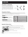
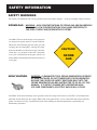
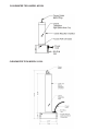
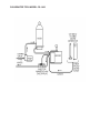
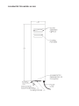
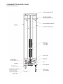
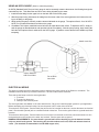
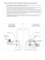
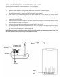
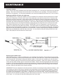
Ozone Systems
......................................................................................................................................
Installation & Maintenance Manual
MZ-250, S-1200
CS-1400 & UV-2800
Ultraviolet Ozone Generators
ClearWater Tech, LLC.
Intrgrated Ozone Systems
850-E Capitolio Way, San Luis Obispo, Ca 93401 • 805-549-9724 • Fax: 805-549-0306 • E-mail: [email protected] •www.cwtozone.com
Copyright © 2002 - ClearWater Tech, LLC. • Reproduction of any kind is prohibited • LIT500 • REV071205
O
3
Introduction
............................................................................................................................
This Installation and Operation Manual is
written to assist in the installation, operation
and maintenance of ozone delivery systems
manufactured by ClearWater Tech, LLC. The
equipment has been designed using the most
modern materials and technology available.
Please read this manual carefully and in its
entirety before proceeding with any installation, operation or maintenance procedure
associated with this equipment. Failure to
follow these instructions could result in
personal injury, damage to the equipment or
reduced product performance.
In an ongoing effort to improve reliability
and operating efficiency, ClearWater Tech
may find it necessary to make changes to its
products. Therefore, the information contained
in this manual may not conform in every
respect to earlier versions of ClearWaterTech
ozone systems found in the field. If you have
any questions, please contact your ClearWater
Tech dealer or the ClearWater Tech service
department.
OVERVIEW
How Ozone is Generated
Ozone is generated by exposing oxygen molecules (O2)
in an air stream to a controlled, high energy electrical
field. As the air stream passes through the electrical field produced inside the ozone generator, some
oxygen molecules are split, forming single oxygen
atoms (O1). These oxygen atoms then recombine with
other O2 molecules in the air stream, forming ozone
(O3).
Ozone (O3)
Oxygen (O2)
O3
O1
O2
Electrical Field
O2
O1
O3
Properties of Ozone
Ozone is the most powerful oxidizer available that can be safely used in water treatment.1 It is used to treat drinking water, bottled water, swimming pool water, wastewater, food and beverage processing water, and in many other
applications. Ozone is effective in performing the following water treatment functions:
• Disinfection – Bacterial disinfection, inactivation
of viruses and cysts.
• Oxidation
of Inorganics – Precipitates iron, manganese, sulfides, nitrites and organically-bound heavy metals.
• Oxidation of Organics – Including organics causing color, taste and odor problems, some
detergents and pesticides, phenols, VOCs, turbidity control and microflocculation of soluble organics.
Molecular weight:
Odor:
Readily detectable at concentrations above 0.02 ppm in air
Color:
Bluish in ozone generator cell, but ozone/air mixture exiting
generator is invisible – even at high ozone concentrations.
Gas Density:
48
Solubility:
2.144 grams/liter at 32°F (approx. 150% that of oxygen).
Only partially soluble in water, but about 10-20 times more
soluble than oxygen (at 68°F).
Benefits of Ozone Use
• Ozone is generated on site – no transportation or storage is required.
• The most powerful oxidizer commercially available – very effective for
disinfection and oxidation without handling problems.
• Ozone creates no potentially harmful by-products (such as THMs) – the only
by-product is oxygen.
• Ozone leaves no telltale taste or odor.
References
1. Water Quality Association, “Ozone for POU, POE and Small Water System Water Treatment Applications,” Lisle, IL, 1999.
SAFETY INFORMATION
SAFETY WARNINGS
Two aspects of ClearWater Tech ozone generators represent potential dangers – ozone gas and high voltage electricity.
Ozone Gas - WARNING: HIGH CONCENTRATIONS OF OZONE GAS ARE DANGEROUS TO HUMANS. LOW CONCENTRATIONS CAN CAUSE IRRITATION TO THE EYES, THROAT AND RESPIRATORY SYSTEM.
ClearWater Tech corona discharge ozone generators
are designed to operate under a vacuum condition.
While this would normally prevent ozone gas from
escaping into the atmosphere, entering the equipment area should be avoided if ozone gas is detected.
Ozone has a very distinctive odor and is detectable
at very low concentrations (0.02 ppm), which is far
below OSHA’s maximum permissible exposure level
of 0.1 ppm.
CAUTION!
OZONE
GAS
High Voltage - WARNING: CLEARWATER TECH OZONE GENERATORS OPERATE AT HIGH VOLTAGES. DO NOT TAMPER WITH OR DELIBERATELY BYPASS THE COVER OR SAFETY SWITCHES BUILT INTO THE OZONE GENERATOR UNLESS INSTRUCTED TO DO SO BY THIS MANUAL. IF CONTACT IS MADE WITH OPERATING HIGH VOLTAGE COMPONENTS, ELECTRIC SHOCK WILL OCCUR.
ClearWater Tech corona discharge ozone generators take line voltage and convert it to 48 VDC. A transformer then
takes that current and boosts the voltage. While each ozone generator has a cover switch and other safety interlocks,
proper care must be used by a qualified electrician when making any internal adjustments or performing any
maintenance procedures.
IMPORTANT SAFETY INSTRUCTIONS -
When installing and using this
electrical equipment, basic safety precautions should always be followed, including the following:
1.
READ AND FOLLOW ALL INSTRUCTIONS.
2.
3.
All electrical connections should be made by a licensed, qualified electrician.
SAVE THESE INSTRUCTIONS.
4.
Before attempting any electrical connections, be sure all power is off at the main circuit breaker.
5.
Install all electrical equipment at least five feet from any open body of water using non-metallic plumbing.
6.
Install check valves and a vacuum break to prevent water from contacting the electrical equipment.
7.
The electrical supply for this product must include a suitably-rated switch or circuit breaker to open all
ungrounded supply conductors to comply with Section 422-20 of the National Electrical Code, ANSI/NFPA
70-1987. The disconnecting means must be readily accessible to the operator(s) but installed at least five
feet from any open body of water.
8.
Conforming with all local, state and national electrical codes, properly bond (ground) the HDO3 system
using the copper bonding lug on the bottom of the ozone generator.
9.
The system should be sized appropriately for its intended use by a qualified professional familiar with the
application. This equipment must be validated by the manufacturer for its intended use.
INSTALLATION
ULTRAVIOLET (UV) OZONE SYSTEMS
Ozone is manufactured in the UV ozone generator by drawing in air, which is composed of 20% oxygen (O2), and
exposing it to the radiation of a specific wavelength from a specially designed ultraviolet lamp. This causes a percentage of the oxygen molecules to dissociate and reassemble as ozone (O3). The ozone is drawn into the water by
an injector/mixer, killing any bacteria, viruses or mold spores it contacts. Ozone is generated on-site, eliminating the
need to store toxic and corrosive chemicals. The corona discharge method is the most efficient way to produce large
amounts of ozone.
Chemical Formula (simplified)
for Corona Discharge Ozone
3 - O2
2 - O3
ClearWater Tech ozone systems are capable of oxidizing iron, sulfide, manganese and act as an efficient sanitizer in a
variety of applications. Ozone reacts to water-borne contaminants significantly faster than other disinfectants and the
primary by-product is pure oxygen.
ClearWater Tech ozone systems are built with the finest components available. They are most efficient when used
with a venturi injection system to create the best possible contact and mixing of ozone while maintaining a high level
of safety.
UNPACKING and INSPECTION
Shipping Terms
Unless special arrangements have been made, the ozone equipment will be shipped FOB ClearWater Tech's factory
in San Luis Obispo, CA. The freight charges will be prepaid and billed or shipped freight collect. Transfer of liability
to the freight company and the customer occurs as the equipment leaves the factory loading dock and is accepted by
the freight line.
Freight Inspection
All equipment should be thoroughly inspected immediately upon delivery. If any damage is noticed, promptly notify
the freight line and request an on-site inspection.
Unpacking
Compare the components with the packing list. Thoroughly inspect all packing materials prior to discarding. Inspect
all plumbing fittings and tubing for packing material inadvertently lodged in any openings.
MOUNTING
Pick a location as close to the injector as possible to mount the ozone generator. While the ozone generator enclosures are rain tight, it is best to pick a location out of the sun and rain.
On the back / top side of the enclosure are mounting holes; the unit can be attached to a wall using these mounting
holes.
CLEARWATER TECH MODEL MZ-250
CLEARWATER TECH MODEL S-1200
CLEARWATER TECH MODEL CS-1400
CLEARWATER TECH MODEL UV-2800
CLEARWATER TECH MODEL UV-2800
Internal Components
USING AN SCFH GAUGE (Must be ordered separately)
An SCFH (Standard Cubic Feet per Hour) gauge is used to accurately measure the amount of air flowing through the
ozone delivery line. This affects the amount of ozone being injected into the water.
1. Install the tube fitting into the upper hole on the back side of the SCFH gauge.
2. With the pump running, disconnect the tubing from the ozone outlet of the ozone generator and connect the tubing to the fitting on the gauge.
3. While holding the gauge vertically, read the amount indicated on the gauge. The optimum flow is 10 to 20 SCFH.
NOTE: Do not obstruct the bottom air hole on the gauge.
4. ClearWater Tech injector manifolds have a ball valve to adjust the amount of flow. To adjust the SCFH, simply install the gauge as described above and open the ball valve completely. With the pump running, begin closing the
ball valve until optimum flow is achieved on the SCFH gauge. If possible, remove the ball valve handle to prevent
tampering.
Attach ozone line
KEEP
GAUGE
VERTICAL
Injector Manifold
with Check Valve
Do not block
lower hole
ELECTRICAL WIRING
The object is to have the ozone generator come on whenever the pump comes on for filtration or circulation. The
installation should be done by a licensed electrician. All local codes must be observed.
There are several ways to wire the ozone generator:
1. To a timer.
2. To a service disconnect
3. Directly to the electrical panel.
The ozone generator is available in 120 volts and 240 volts. Be sure to install the proper system for your application.
Before attempting any electrical hookup, be sure the power is OFF at the main circuit box.
To hard wire a 120V system: Run the black (hot) wire to the ‘hot’ terminal on the timer, service disconnect or electrical
panel. Run the white (neutral) wire to a neutral terminal or buss bar. Then run the ground wire to a ground terminal or
buss bar.
To hard wire a 240V system: Run the black wire to one of the ‘hot’ terminals on the timer, service disconnect or electrical panel and run the red wire to the other ‘hot’ terminal. Run the green wire to ground.
BONDING REQUIREMENTS: You must install a ground lead from the bonding lug (on the bottom left of the
unit) to a natural earth ground. This bonding wire should conform to all local, state and national electrical
codes. (The standard recommendation is a #8 AWG copper wire.)
TYPICAL INSTALLATION FOR ATMOSPHERIC TANK RECIRCULATION SYSTEM
1.
When ClearWater Tech ozone generator units are to be used for atmospheric tank recirculation, observe all
general installation steps and electrical connection instructions.
2.
On an ozonated recirculation system, all pumps and venturis should be protected by valves and unions to
facilitate servicing. In general, low pressure check valves may be used on the venturi.
3.
A typical recirculation system should inlet from the bottom of the tank and return to the bottom of tank, forcing
the water in a circular pattern (even if the piping must extend over from the top of the tank to the bottom).
4.
If an ORP monitor is to be used for ozone residual indication or control, the sensor should be mounted between the tank isolation valve and the pump inlet. This is also a good location for a flow meter. (Observe the
manufacturers recommendations for flow meter installation.)
5.
Depending on water quality and ozone generator size, a 24 hour timer or delay timer is a useful accessory.
For additional information on tank turnover times, alternative techniques or accessories, consult your
ClearWater Tech representative.
OR
Style A Circulator
Reverse Osmosis and
Water Storage Tanks
up to 1500 Gallons
Style B Circulator
Treatment and Storage
Tanks up to 20,000 Gallons
Isolation Valve
Isolation Valve
From
Ozone Generator
Ozone from
ozone generator
Venturi
Injector
Low Pressure
Check Valve
ClearWater Tech
PRO 10/12/14
Circulation Pump
Unions
Isolation Valve
Isolation Valve
ORP Probe
INSTALLATION WITH THE CLEARWATER TECH OAS-20 UNIT:
Typical pressurized installation for water treatment or odor control system
1.
Mount the OAS-20 and the ozone generator adjacent to each other on a sheltered surface.
2.
Remove the cover mounting screws on the ozone generator and locate the barbed air inlet fitting at the bottom
of the UV lamp chambers. (See the unit illustrations earlier in this manual.)
3.
Cut a length of 1/4" braided tubing provided and attach between the air outlet fitting on the OAS-20 and the
barbed inlet air fitting on the ozone generator.
4.
Connect the remaining 1/4" braided tubing to the barbed fitting on the ozone outlet of the ozone generator (the
check valve on the UV‑2800).
5.
Connect the opposite end of this tubing to the ozone dispersion ring and place in the bottom of the tank, running
the tubing above the water level of the tank.
6.
Plug the ozone generator power cord into the switched outlet on the OAS-20.
7.
To initiate operation, set the timer by rotating the blue timer dial clockwise to indicate the current time of day.
Pull outward on the blue tabs to indicate the current time of day. Pull outward on the blue tabs to engage the
air source at the indicated time for 30 minutes per tab.
NOTE: Extreme caution should be exercised if this unit is to be used for open atmospheric odor control. The
use of an ambient air monitor is strongly recommended for safety.
Ozone
Air Outlet
120 VAC
ClearWater Tech
Air Source/Timer
Air
120 VAC
Ozone
Dispersion
Ring
MAINTENANCE
The Ozone Lamp(s)
Caution: Never look at the unshielded ozone lamp while operating the unit. This lamp can cause severe eye and skin
damage. There is an indicator light which will turn blue in color when the unit is operating. The lamps each have a
9,000 hour life expectancy. On commercial installations, we recommend replacing the lamps every 12 to 18 months.
Replacing the MZ-250, S-1200 or CS-1400 Lamp:
(See illustration below.) Lamps are available from your ClearWater Tech distributor should replacement be needed.
Simply turn off the power, remove the two screws on the power pack cover and remove the cover. Disconnect the
plug on the end of the ozone lamp. Using a pair of pliers or channel locks, loosen the lamp holder locking ring from
around end of lamp by turning it counterclockwise and remove it. Remove the lamp by grabbing the rubber bushing
around the end of the lamp and pulling it straight out. Remove the rubber bushing from the lamp and install it on your
new lamp making sure the outer edge of the bushing is flush with the outer edge of the silver end cap on the lamp.
Now, slide the lamp back into the reaction chamber. IMPORTANT! There is a depression in the other end of the
chamber for centering the lamp within the chamber. Care must be taken to make sure the lamp is inserted into this
depression before the lamp holder is tightened. The lamp holder may now be reinstalled and tightened. Reinstall the
plug onto the lamp and replace the power pack cover and screws. Caution: Keep lamp free of fingerprints and dust
particles by only handling the metal end caps on the lamp. You can clean the lamp with rubbing alcohol and a soft
cloth. A dirty lamp will not allow maximum ozone output.
Replacing the UV-2800 Lamps
(See illustration above.) Lamps are available from your ClearWater Tech distributor should replacement be needed.
Simply turn off the power, remove the six screws on the cover and remove the cover. Push in on the ultraviolet chamber and unsnap the "click-clamps" holding the chamber in place. Lift the end of the chamber up to clear the end of
the unit. Disconnect the plug on the end of the ozone lamp(s) to be replaced. Using a pair of pliers or channel locks,
loosen the lamp holder locking ring from around the end of lamp. Remove the lamp by grasping the rubber bushing
around the end of the lamp and pulling it and the lamp straight out. Remove the rubber bushing from the lamp and
install it on your new lamp making sure the outer edge of the bushing is flush with the outer edge of the end cap on
the lamp. Slide the lamp back into the reaction chamber.
IMPORTANT! There is a depression in the other end of the chamber for centering the lamp within the chamber. Care
must be taken to make sure the lamp is centered into this depression before the lamp holder is tightened. Replace
the lamp holder locking ring and reinstall the plug onto the lamp. Resecure the chamber clamp(s) by pushing in on
the chamber and resnapping the "click-clamps" . Replace the unit cover and screws. Caution: Keep lamp free of
fingerprints and dust particles by handling only the metal end caps on the lamp. A dirty lamp will not allow maximum
ozone output. You can clean the lamp with rubbing alcohol and a soft cloth.
troubleshooting
PROBLEM/SYMPTOM
POSSIBLE CAUSE
SOLUTION
Unit does not turn on
No power to unit
Check breakers
Switch not turned on
Check switch
Blown fuse
Replace fuse
Cover/door interlock not active
(UV-2800 only)
Check door interlock switch
replace cover
Unit does not stay on
(UV-2800 only)
Unit overheating
Clean fan filter, check fan
Only one ozone chamber Bad lamp or ballast
lights (UV-2800 only)
Switch ballast connections between
chambers - if opposite chamber lights,
replace ballast;
if same one lights, replace lamp
Water in unit or
ozone delivery tubing
Inadequate vacuum
Adjust injector vacuum
Defective check valve(s)
Replace check valve(s)
Excessive back pressure on check valve
Back pressure not to exceed 40 psi if over 40 psi consult ClearWater Tech
dealer
Ozone smell present
Insufficient vacuum
Adjust injector vacuum
Loose internal fittings
Inspect and tighten fittings
Defective ozone chamber
Replace chamber
REPLACEMENT
PART #
PARTS
DESCRIPTION
QUANTITY REQUIRED
MZ-250 S-1200CS-1400UV-2800
PAB20......Parts Bag: includes Saddle Clamp with Fitting and O-ring,
1/4" Kynar® Check Valve, 1/4" barb x 3/8" threaded Kynar® Fitting, Screws (5).......... 1.......... 1...... N/A.......N/A
PAB15......Parts Bag: same as PAB20 above, plus Hose Clamps (3)....................................... N/A...... N/A.......... 1.......... 1
CKV60.....1/4" Kynar® Check Valve (included in Parts Bags above)............................................ 1.......... 1.......... 1.......... 2
DLV25......Ozone Delivery Line, 1/4" clear tubing for MZ-250 & S-1200................................... 20'....... 20'...... N/A.......N/A
DLV10......Ozone Delivery Line, 1/4" braided tubing for CS-1400 & UV-2800.......................... N/A...... N/A........20'........20'
CKV20.....1/4" threaded Kynar® Check Valve (installed on ozone outlet of UV-2800 only)...... N/A...... N/A...... N/A.......... 1
LA40........Ozone Lamp for MZ-250.............................................................................................. 1...... N/A...... N/A.......N/A
LA15........Ozone Lamp for S-1200............................................................................................... 1...... N/A...... N/A.......N/A
LA25........Ozone Lamp(s) for CS-1400 & UV-2800.................................................................. N/A...... N/A.......... 1.......... 2
BL45........Ballast, thermally protected, self-starting, 120VAC, 60 Hz for MZ-250........................ 1...... N/A...... N/A.......N/A
BL25........Ballast, thermally protected, self-starting, 120VAC, 60 Hz for S-1200/CS-1400...... N/A.......... 1.......... 1.......N/A
BL55........Ballast, thermally protected, self-starting, 240VAC, 60 Hz for S-1200..................... N/A.......... 1...... N/A.......N/A
BL30........Ballast, electronic, 120VAC, 60 Hz for UV-2800...................................................... N/A...... N/A...... N/A.......... 1
BL60........Ballast, thermally protected, self-starting, 240VAC, 60 Hz for CS-1400/UV-2800... N/A...... N/A.......... 1.......... 2
FA20........Cooling Fan Filter Element....................................................................................... N/A...... N/A...... N/A.......... 1
MZ-250 SPECIFICATIONS
ENERGY REQUIRED:..................................................................................... 105 VAC MIN., 125 VAC MAX., .350 AMP
POWER CONSUMPTION:................................................................................................................................ 38 WATTS
RATED:................................................................................. ATMOSPHERIC STORAGE TANKS UP TO 250 GALLONS
AVERAGE LAMP LIFE:............................................................................................................................... 9,000 HOURS
LAMP WAVELENGTH:........................................................................................................................................... 185 nm
DIMENSIONS:..........................................................................................................................11.00"H x 4.75"W x 4.25"D
SHIPPING WEIGHT:................................................................................................................................................5 LBS.
S-1200 SPECIFICATIONS
ENERGY REQUIRED S-1200 110V:.................................................................. 105VAC MIN., 125VAC MAX., .640 AMP
ENERGY REQUIRED S-1200 240V:.......................................................................210VAC MIN., 245V MAX., .320AMP
POWER CONSUMPTION:................................................................................................................................ 40 WATTS
RATED:................................................................................. ATMOSPHERIC STORAGE TANKS UP TO 500 GALLONS
AVERAGE LAMP LIFE:............................................................................................................................... 9,000 HOURS
LAMP WAVELENGTH:........................................................................................................................................... 185 nm
DIMENSIONS:......................................................................................................................... 19.75"H x 7.50"W x 4.25"D
SHIPPING WEIGHT:................................................................................................................................................7 LBS.
CS-1400 SPECIFICATIONS
ENERGY REQUIRED 120V:.................................................................... 105VAC MIN., 125VAC MAX., 60HZ., 0.8 AMP
POWER CONSUMPTION:................................................................................................................................ 96 WATTS
RATED FOR:...................................................................... ATMOSPHERIC STORAGE TANKS UP TO 1000 GALLONS
AVERAGE LAMP LIFE:............................................................................................................................... 9,000 HOURS
LAMP WAVELENGTH:........................................................................................................................................... 185 nm
DIMENSIONS:.......................................................................................................................... 31.25"H x 7.5"W x 4.25"D
SHIPPING WEIGHT:..............................................................................................................................................15 LBS.
UV-2800 SPECIFICATIONS
ENERGY REQUIRED UV-2800 120V:..................................................... 105VAC MIN., 125VAC MAX., 60HZ., 1.6 AMP
ENERGY REQUIRED UV-2800 240V:.......................................................... 210VAC MIN., 245V MAX., 60HZ., 0.8 AMP
POWER CONSUMPTION:.............................................................................................................................. 192 WATTS
RATED FOR:...................................................................... ATMOSPHERIC STORAGE TANKS UP TO 2500 GALLONS
AVERAGE LAMP LIFE:............................................................................................................................... 9,000 HOURS
LAMP WAVELENGTH:........................................................................................................................................... 185 nm
DIMENSIONS:.................................................................................................................................. 32"H x 8.5"W x 3.5"D
SHIPPING WEIGHT:..............................................................................................................................................25 LBS.
ClearWater Tech, LLC. Limited One-Year Warranty
Summary of the Warranty
ClearWater Tech, LLC (“CWT”) makes every effort to assure that its products meet high quality and durability standards and warrants the products
it manufactures against defects in materials and workmanship for a period of one (1) year, commencing on the date of original shipment from CWT,
with the following exceptions: 1) The warranty period shall begin on the installation date if the installation is performed within 90 days of the original shipment from CWT; 2) The warranty period shall begin on the date of the bill of sale to the end user if the installation date is more 90 days after
the original shipment date. To validate the warranty, a warranty card, accompanied by a copy of the bill of sale, must be returned to CWT and must
include the following information:
•
•
•
•
•
End user name
Complete address, including telephone number
Date installed
Complete model and serial number information
Name of company from which the unit was purchased
Repairs and replacement parts provided under this warranty shall carry only the unexpired portion of this warranty or 90 days, whichever is longer.
Items Excluded from the Warranty
This warranty does not extend to any product and/or part from which the factory assigned serial number has been removed or which has been damaged or rendered defective as a result of:
• An accident, misuse, alteration or abuse
• An act of God such as flood, earthquake, hurricane, lightning or other disaster resulting only from the forces of nature
• Normal wear and tear
• Operation outside the usage parameters stated in the product user’s manual • Check valve/solenoid valve failure
• Use of parts not sold by CWT
• Damage which may occur during shipping
• Service or unit modification not authorized by CWT
• Failure to meet service requirements as outlined in the I & O manual
Obtaining Service Under the Warranty
Any product and/or part not performing satisfactorily may be returned to CWT for evaluation. A Return Goods Authorization (RGA) number must
first be obtained by either calling or writing your local authorized dealer, distributor or CWT direct, prior to shipping the product. The problem experienced with the product and/or part must be clearly described. The RGA number must appear prominently on the exterior of the shipped box(es).
The product and/or part must be packaged either in its original packing material or in comparable and suitable packing material, if the original is not
available. You are responsible for paying shipping charges to CWT and for any damages to the product and/or part that may occur during shipment.
It is recommended that you insure the shipment for the amount you originally paid for the product and/or part.
If, after the product and/or part is returned prepaid and evaluated by CWT, it proves to be defective while under warranty, CWT will, at its election, either repair or replace the defective product and/or part and will return ship at lowest cost transportation prepaid to you except for shipments
going outside the 50 states of the United States of America. If upon inspection, it is determined that there is no defect or that the damage to the
product and/or part resulted from causes not within the scope of this limited warranty, then you must bear the cost of repair or replacement of damaged product and/or part and all return freight charges. Any unauthorized attempt by the end user to repair CWT manufactured products without
prior permission shall void any and all warranties. For service, contact your authorized dealer or distributor or CWT direct at (805) 549-9724, extension 23.
Exclusive Warranty
There is no other expressed warranty on CWT products and/or parts. Neither this warranty, or any other warranty, expressed or implied, including
any implied warranties or merchantability of fitness, shall extend beyond the warranty period. Some states do not allow limitations on how long an
implied warranty lasts, so that the above limitation or exclusion may not apply to you.
Disclaimer of Incidental and Consequential Damages
No responsibility is assumed for any incidental or consequential damages; this includes any damage to another product or products resulting from
such a defect. Some states do not allow the exclusion or limitation of incidental or consequential damages, so that above limitation or exclusion may
not apply to you.
Legal Remedies of Purchaser
This warranty gives you specific legal rights and you may also have other rights which vary from state to state.
THIS STATEMENT OF WARRANTY SUPERSEDES ALL OTHERS PROVIDED TO YOU AT ANY PRIOR TIME.