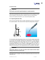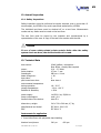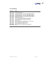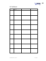
1
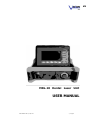
EN
MDL-10 Dental Laser Unit
USER MANUAL
USER MANUAL MDL-10 / Sept 2003
1 / 39 pages
EN
IMPORTANT !
This manual contains information that is subject to copyright. All rights
reserved. This manual should not be photocopied, duplicated on microfilm
or otherwise copied or distributed, completely or in part, without the
approval of VISON LASERTECHNIK GmbH.
Some of the parts and equipment referred to in this manual bear
registered trademarks but are not identified as such. It should therefore
not be assumed that the absence of the trademark indicates that any
given designation is not subject to trademark protection.
Users of VISION LASERTECHNIK GmbH products should not hesitate to
point out to us any errors or unclarities in this manual.
Copyright © VISION LASERTECHNIK GmbH.
Manufacturer:
VISION LASERTECHNIK GmbH
Dammweg 1
31552 Rodenberg
Germany
Tel: +49-5723-4624
Fax: +49-5723-75342
USER MANUAL MDL-10 / Sept 2003
2 / 39 pages
EN
Important Note
Read this manual
Read this user manual thoroughly and familiarize yourself with the use and
functioning of the device and all accessories prior to using the device in the
operating room. Failure to follow these instructions may result in:
• Serious injury to the patient
• Serious injury to the operating team or service personnel, or
• Damage to or a malfunction of the device or accessories.
Modification
The manufacturer reserves the right to modify the appearance and technical
performance of the product through continued development of the production of
the product.
Please read this manual completely and follow its instructions carefully. The
sections labelled WARNING, CAUTION and NOTE contain important information.
Read these sections carefully.
WARNING or DANGER
The safety of the patient, the operating team or a third party is a risk.
Disregarding this information could result in injury to the patient.
CAUTION
These instructions point out special service procedures or precautions
that must be followed to avoid damaging the device.
NOTE
This provides special information that facilitates maintenance of
clarifies important instructions.
CE0482 /
MED
CERT
CE marking according to Directive 93/42/EEC
Index
USER MANUAL MDL-10 / Sept 2003
3 / 39 pages
EN
Copyright information
About this manual
Index
2
3
4
1.
Safety instructions
1.1. Warnings
6
7
2.
Purpose of the Device
2.1. Intended Use
2.2. Mechanism of Action
2.3. Laser Radiation, Safety Regulations, Laser Class
2.4. Aiming Beam
2.5. Laser Area
2.6. Instructions to Personnel and Notification
of Laser Operation
2.7. Protective Laser Goggles, Protective Clothing
2.8. Miscellaneous hazard instructions
2.9. Laser Fiber
2.9. Labelling of Laser
6
6
6
7
7
7
9
9
10
10
10
3.
Initial Operation
3.1. Installation
10
13
4.
Operation of the Device
4.1. Front of the device
4.2. Rear of the device
4.3. Operator panel
4.4. Foot switch
4.5. Start up
4.6. Setting of Mode & Parameters
4.7. All parameters
4.8. Stand-Bye / Ready
4.9. Activating the foot switch
4.10. Warning display and noise during laser operation
4.11. Switch off
14
15
15
16
16
16
17
18
19
20
20
21
5.
Laser Fiber
5.1. General description and warnings
5.2. Precautions when using the fiber with an endoscope
22
23
24
6.
Safety Functions
6.1. Warning Equipment during laser emission
6.2. Safety Components
6.3. Access control
6.4. Safety related accessories
6.5. Safety inspections
27
27
27
28
28
28
7.
User manual
28
8.
Options
28
USER MANUAL MDL-10 / Sept 2003
4 / 39 pages
EN
9.
Function test
9.1. Inspecting the laser fiber
29
27
10. Operating the laser
10.1. Aiming beam
10.2. Adjusting mode, power and other parameters
10.3. Use of the device
10.4. Replacing the fiber
10.5. Trimming the laser fiber during the procedure
10.6. Possible hazards resulting from improper operation
31
31
31
31
33
33
31
11. Service and maintenance
11.1. Cleaning the device
11.2. Cleaning the laser fiber
11.3. Maintenance
32
32
35
35
12. Annual Inspection
12.1. Safety inspections
35
35
13. Technical Data
36
14. Accessories
37
15. Trouble shooting instructions
38
16. Test record
39
USER MANUAL MDL-10 / Sept 2003
5 / 39 pages
EN
1. Safety Instructions
Warranty
The manufacturer warrants that the device and the accessories will be free from
manufacturing and material defects for one (1) year from initial operation. The
warranty is limited to the terms and conditions described herein, and there are
no other warranties, expressed or implied.
No Liability
The manufacturer shall not be liable for direct or incidental damage, and the
warranty shall become void if:
•
•
•
•
•
•
The device or the accessories are improperly used;
The instructions and rules in the manual are not adhered to;
The device or the accessories are improperly prepared or serviced;
Unauthorized persons perform repairs, adjustments or alterations on the
device or accessories;
An unauthorized person perform repairs, adjustments or alterations on
the device or accessories;
The prescribed inspection and maintenance schedule is not adhered to.
Authorized Service Technician
Only an authorized service technician may perform repairs, adjustments, or
alterations on the device or accessories.
Care
To guarantee safe operation, it is absolutely necessary to carry out proper care of
the device and accessories. For the protection of the patient and the operating
team, verify that the device is complete and functional before each use.
New products, as well as repaired products, must be prepared and tested
according to the manual instructions prior to use.
USER MANUAL MDL-10 / Sept 2003
6 / 39 pages
EN
1.1. Warnings
Water hazard: Protect the device from being splashed by water. Keep the key
switch dry. Should any liquid enter the device, discontinue use immediately.
Original accessories: For your own safety, and that of your patient, use only
original accessories.
Internal standard settings: Check all settings that are standard to your work
place. Such internal standard settings are not necessarily prescribed for the
doctors. The physician is responsible for all settings required for his or her
operation.
Specific Technique and Procedures: Only the physician can evaluate the
clinical factors involved with each patient and determine if the use is indicated.
The physician must determine the specific technique and procedure that will
accomplish the desired clinical effect.
Available Voltage: Determine if the available voltage corresponds to your
device. Working with wrong voltage will cause the device to malfunction or may
permanently damage the device.
Not Explosion-proof: Electrical components are not explosion-proof. Do not
use in an area where flammable gases are present.
Risk of Electrical Shock: To reduce the risk of electrical shock, do not remove
cover (or back). Refer servicing to qualified service personnel.
Professional Qualification: This manual does not provide a detailed description of
operation techniques, nor is it suitable for introducing a beginner to this
operating technique. Medical accessories and devices may be used only by
physicians and medical assistants under the directive of a physician with the
appropriate professional qualification.
Function Test: A function test must be performed prior to each operation.
Sterile Substances and Accessories: Always work exclusively with sterile
substances and sterile accessories.
Cleaning the device: Do not sterilize the device.
Replacement fiber: A replacement fiber should be kept in the immediate
vicinity to allow the surgeon to complete the procedure in case of fiber damage.
Specific Device Warnings: Read the specific warnings for this device in
Chapter 2 Purpose of the Device.
Defect: If a defect is suspected or confirmed, stop using the device until it has
been checked by authorized service personnel. This also applies if the device fails
to maintain the indicated tolerance levels.
Endoscope: The device may only be connected to endoscopes designed for the
use with the device for the intended medical procedure. The endoscopes must
comply with the most recent versions of IEC 601-2-18 and ISO 8600.
Servicing and Adjusting: Do not open the device. The device must not be
serviced or adjusted by the user. Only authorized technicians may perform
repairs, adjustments or alterations to the device or to its accessories.
Exposure to Hazardous Radiation: Use of controls or adjustments or
performance of procedures other than those specified herein mnay result in
exposure to hazardous radiation.
USER MANUAL MDL-10 / Sept 2003
7 / 39 pages
EN
2. Purpose of the Device
2.1. Intended Use
The VISION laser MDL-10 is a diode laser (GaAl) with a wavelength of 980 nm.
This laser radiation is suitable for cutting or coagulating soft tissue as well as for
activating photochemical processes (Bleaching). If the laser radiation is used at
very low energy densities it is suitable for therapeutic applications.
Indications for Use
The VISION laser MDL-10 is a surgical laser device for use in soft tissue
treatment in dentistry, e.n.t., and other medical applications.
Contraindications
The laser beam (end of the fiber) should not be used on mineralised tissues like
enamel, dentine or bones to avoid damages by overheating.
2.2. Mechanism of Action
The laser beam produced by the VISION laser unit MDL-10 emits pulses with a
repetition rate from 1 to 1000 pulses per second. This repletion rate is
adjustable. The laser beam is transferred to the point of action through the laser
fiber, exiting the distal end of the fiber as a divergent beam. The laser energy will
be transformed into heat, which will interact with the desired tissue by cutting or
coagulating or by activating of chemical substances or in case of very low energy
densities by photon activated therapeutic interactions.
2.3. Laser Radiation, Safety Regulations, Laser Class
Laser Radiation: The VISION laser device MDL-10 produces laser radiation.
Laser radiation is defined as electromagnetic radiation in the wavelength range
from 100 nm to 1 mm in the form of controlled, stimulated emission. The VISION
laser device MDL-10 produces laser radiation with a wavelength of 980 nm by
stimulated emission of a electrical excited GaAl – diode.
Safety Regulations: All safety precautions according to IEC 825 (“Radiation
Safety for Laser Equipment”) must be observed to protect the patient and the
user. Before using the VISION laser device MDL-10, the patient must be informed
of the mode of operation of the application. The VISION laser device MDL-10 is a
Class 4 laser device.
Laser Class: Class 4 means that direct as well as diffuse indirect radiation can
be dangerous to skin and eyes. Proper use of the device, however, has a healing
affect to the patient if the use of the radiation is targeted. Nonetheless,
uncontrolled emission of radiation can be dangerous and this requires that
appropriate safety measures be taken.
USER MANUAL MDL-10 / Sept 2003
8 / 39 pages
EN
2.4. Aiming Beam
An aiming beam is incorporated within the device to direct the fiber to its target
and to control the fiber quality. This beam is visible at the distal end of the fiber
as a red light (wavelength 635 nm, hazard class of laser 3B) and is harmless.
WARNING
Never look directly into the end of the fiber laser (aiming beam and/or
treatment beam) while the laser is activated ! This can cause damage
to the retina !
CAUTION
The laser must not be operated if the aiming beam is not visible
The total laser radiation output always includes the aiming beam. For definition
purposes, the portion of the laser radiation used to tissue interaction with its
wavelength of 980 nm, is identified as “treatment beam”.
If the aiming beam is not visible prior or during the operation, the laser treatment
must be aborted.
2.5. Laser Area
The laser area in the context of the above regulations is identified as the
enclosed space in which the VISION laser device MDL-10 is set up to used and
which is separated from other spaces by means of solid walls and doors. Ensure
that the laser area contains no highly reflective surfaces such as mirrors.
The use must identify the laser area as such. This is to be done by posting laser
warning signs “WARNING – LASER RADIATION” according to IEC 825. Signs are
commonly available throughout the industry and can also be obtained from
VISION upon request. A hazard sign is included with these instructions.
At all entrances of the laser area, care must be taken so that no person is
exposed to laser radiation by inadvertently entering the area. For this purpose,
laser warning lamps must be located outside of the entrances to the laser area to
indicate the laser is in operation. Door switches may be used to ensure the laser
is switched off in case of unauthorized entry.
All existing entrances and windows should be fitted with protective laser curtains.
An equivalent degree of safety may be achieved by using laser radiation curtains.
USER MANUAL MDL-10 / Sept 2003
9 / 39 pages
EN
2.6. Instructions to Personnel and Notification of Laser
Operation
Observe applicable national guidelines regarding:
•
•
•
•
Instructing personnel in laser operating
Registering laser operation with public authorities
Documenting maintenance intervals
Emergency shut off the laser
Verify that all applicable regulations have been observed before operating the
unit.
CAUTION
The respective public authorities should be informed of plans to
operate laser equipment prior to initial operation of the laser
2.7. Protective Laser Goggles, Protective Clothing
WARNING
All persons in the laser area, including the patient, must always wear
protective laser goggles to avoid eye injury. Failure to wear protective
laser goggles can result in severe injury to the eyes including blindness
1
WARNING
Never look directly into the end of the fiber laser (aiming beam and/or
treatment beam) while the laser is activated ! This can cause damage
to the retina !
Since the intensity of the laser radiation exceeds the maximum permissible limit
for radiation, all persons within the laser area must wear appropriate laser
protective eyewear and clothing to protect their eyes and skin. The operator must
provide appropriate protection.
Protective eyewear for the laser radiation at 980 nm must be identified as
protective laser goggles according to ANSI Z136.1. The protective eyewear in use
must have an 980/L4 degree of protection that corresponds to the intensity and
type of laser radiation emitted from the VISION laser device MDL-10.
Always wear protective laser goggles when preparing the fiber. This prevents
possible eye injuries from fiber splinters.
Protective laser goggles are available from VISION. Any sturdy clothing can be
used as protective clothing.
USER MANUAL MDL-10 / Sept 2003
10 / 39 pages
EN
2.8. Miscellaneous Hazard Instructions
The area at which the laser is emitted, i.e. the distal end of the fiber, has a very
high radiation energy and power density. Up to approximately 1 cm in front of
the fiber exit surface, the laser radiation energy density is very high and can
ignite easily flammable materials. Therefore, the irradiation of flammable material
must be avoided.
2.9. Laser Fiber
To ensure perfect function and to guarantee laser safety, only laser fibers that
have been approved by VISION may be used. AN important factor in the safe
application of the laser radiation in the area of intended use is the optical quality
of the fiber transmission. This system consists of the fiber plug and the optical
fiber. Only original parts guarantee safe beam guidance within the fiber and
correct beam characteristics at the distal end of the fiber.
Incorrect fibers, incorrectly operated devices or broken fibers endanger the
patient and personnel and must never be used.
DANGER
Using a fiber other than the specified fiber can result in dangerous
radiation exposure.
USER MANUAL MDL-10 / Sept 2003
11 / 39 pages
EN
2.10. Labelling the Laser
The VISION laser device MDL-10 is supplied with warning and information signs.
Label No. 1
Label on the front of the laser
Label No. 2
Label on the rear of the laser
Label No. 3
Label on the rear of the laser:
Label No. 4
Label on the rear of the laser:
USER MANUAL MDL-10 / Sept 2003
12 / 39 pages
EN
3. Initial Operation
Initial Inspection
Check the device and all accessories immediately upon receipt to make sure
contents are complete and nothing is damaged.
Returning the Device
If it becomes necessary to return the device, the original packaging must be
used. The manufacturer shall assume no responsibility for damage that has
occurred during shipping if the damage was caused by inadequate shipping
packaging.
Please
•
•
•
•
•
enclose the following information with the device:
Owners name
Owners address
Type
Serial number of the equipment (see identification plate)
Description of the damage
Setting up the Device
Place the device on a horizontal surface in a dry place. The ambient temperature
should be between 18 – 30 °C (64 – 86 °F), and the relative air humidity should
be between 30 – 75 %.
WARNING
The electrical components are not explosion-proof. Do not use in an
area where flammable gases are present.
Power supply connection
CAUTION
Determine if the available voltage corresponds to your device. Working
with the wrong voltage will cause the device to malfunction or may
permanently damage the device.
The specifications of the main power supply must comply with IEC, CEC and NEC
requirements.
Ensure that the key switch is in the OFF position (vertical position).
Safety Plug
The power supply cable must be equipped with a safety plug. Use the enclosed
power cable for the connection between the power plug and the device socket.
USER MANUAL MDL-10 / Sept 2003
13 / 39 pages
EN
The power plug must be connected to a 220 – 240 V ac protected contact
receptacle with at least 2 A fuse.
Potential Equalization
The equalize potential differences, the VISION laser device MDL-10 can be
connected from the grounding screws at the rear of the device to the groundprotected receptacle in the treatment room using a common grounding cable in
accordance with the local safety regulations.
Ventilation Openings
At the sides of the laser, the housing has air inlet and outlet openings allowing
for air exchange to cool the device. During operation, care must be taken not to
block or hang anything over the at openings.
A 20 cm gap must be maintained to ensure proper cooling function.
3.1. Installation
Prior to operation, verify that the room in which the device is to be set up is free
of materials that can result in electrostatic charge build-up, such as carpeting.
The initial installation of the VISION laser device MDL-10 is performed by VISION
or by a dealer authorized by VISION. Here, an initial operation record will be
filled out. A copy of the initial operation record, signed by the manufacturers
representative and a person authorized by the customer accepting the laser
remains with the customer. At the same time, one or more designated persons
will be trained in the operation of the system; their names are entered into the
training log.
CAUTION
All work on and in the device that is not part of regular operation must
be performed by VISION technicians or persons authorized by VISION
only.
External Door Contact
The VISION laser device MDL-10 has a connection on the rear for a remote
safety interlock according to IEC 825 § 4.4. Opening contacts 1 and 5 in the jack
will cause the system to automatically shut down. A break contact can be
connected between these contacts, which is opened by the entrance door to the
laser area.
However, it is not recommended that door contacts be connected since when the
door is opened, the laser will immediately shut down and treatment will be
interrupted. The system is shipped with a shorting plug for this reason. The
decision to connect the door contact is to be made by the users safety
representative. It is recommended that this issue be discussed with the
appropriate supervisory authorities.
USER MANUAL MDL-10 / Sept 2003
14 / 39 pages
EN
Initial Operation
After all safety precautions have been checked out and the device has been
installed, the VISION laser device MDL-10 can be turned on.
The laser unit is adjusted at the factory. Therefore you should follow the same
procedure during initial operation as in normal operation (see Chapter 4).
USER MANUAL MDL-10 / Sept 2003
15 / 39 pages
EN
4. Operating the Device
4.1 Front of the device
fiber connection
key switch
emergency stop
laser sign
operator panel
change of programs
parameter setting
Ready / Standby
4.2. Rear of the device
foot switch connection
RS232 - interface
SERVICE interface
external door contact
sign for yearly check up
USER MANUAL MDL-10 / Sept 2003
identification plate
mains switch
mains fuses 2 x 2 A mT
mains socket
laser label
16 / 39 pages
EN
4.3 Operator Panel
operation information screen
up / down for program
+ / - change of parameters
MENU / SET – Ready / Standby
accept changes in parameter
program 1 – 5, individual
4.4. Foot Switch
The VISION laser device MDL-10 is operated using a foot switch. The foot switch
consists of the actual foot contact (1) and the securely connected feed cable (2)
with locking plug connection (3). The foot contact is covered by a hood (4) to
keep it from being stepped on inadvertently.
Attaching the foot-switch
1. Connect the foot-switch plug to the foot switch connection at the rear of
the device.
2. Screw on the foot switch plug securely
USER MANUAL MDL-10 / Sept 2003
17 / 39 pages
EN
4.5 Start-Up
1. Connect the mains plug to a suitable power supply.
2. The emergency STOP switch is then unlocked by pulling the red cap.
3. Insert the key and turn on the device by turning the key to the right by
90°
-- check if interlock connector or external interlock circuit is activated -The device will start with an introduction screen of VISION
The laser device is now ready to operate, and the device will perform an internal
system test lasting approximately 5 seconds.
After successful self testing the laser is ready for use.
USER MANUAL MDL-10 / Sept 2003
18 / 39 pages
EN
4.6. Setting of Mode and Parameters
4.6.1.
cw-Mode
with the up/down buttons choose the cw
mode, which is mostly used for surgery. CW
means continues wave, the laser is emitting
always as long it is activated, indicated by
the EM.TIME with an indefinite sign (∞) in
the display.
Use the MENU/SET button to confirm.
In the cw-mode the power can be changed from 0,0 up to 2,5 watts by using
the + / - buttons.
4.6.2.
pulsed-Mode
with the up/down buttons choose the pulse
mode, which is used in periodontology and
endodontology. Pulse means that the laser is
switched on and off
frequency, (here 10 Hz).
in
a
indicated
Use the MENU/SET button to confirm.
In the pulse-mode the power can also be changed from 0,0 up to 2,5 watts
by using the + / - buttons.
4.6.3.
Therapy-Mode
with the up/down buttons choose the
therapy mode, which is used in various
applications, where the laser light should
stimulate. In this mode the laser energy is
very low, far from power level to cut or
coagulate.
Use the MENU/SET button to confirm.
In the therapy-mode the 5 pre-selected application have been already
implemented and can be chosen by the 5 program buttons.
i.e.
Therapy-Program 1:
Pain treatment at open wound surfaces support
for wound healing
Spot size: 1 cm
Power density: 0,13 W/cm2
Dose: 12 J
Emission Time: 120 s
USER MANUAL MDL-10 / Sept 2003
19 / 39 pages
EN
Therapy-Program 2:
desensitisation
Spot size: 1 cm
Power density: 0,13 J/cm2
Dose: 6 J
Emission Time: 240 s
4.6.4.
Pre-selection and storage of application programs
The VISION MDL devices allow to store parameters for different applications
for easier access by the operator. This will be performed by using the
memory keys at the lower rim of the user screen.
Press one of the 5 buttons for at least 3 seconds – and a selection menu
will appear.
Choose one of the shown indications by using the up / down keys and
press the menu / set button to store the parameters.
The
following
suggested:
•
•
•
•
applications
are
ENDODONTICS
PERIODONTICS
SURGERY
BLEACHING
examples
Each time one of the application is activated by using the specified key button,
the application will be highlighted on the screen for some seconds.
USER MANUAL MDL-10 / Sept 2003
20 / 39 pages
EN
4.7. All Parameters
The user can select and change all the programs and parameters by up/down
and +/- buttons, always confirmed by MENU/SET button:
POWER:
MODE:
REPETITION RATE:
PULSE LENGTH:
PULSE PAUSE:
EMISSION TIME:
THERAPY MODE:
1 – 2,5 Watts
cw or pulsed
Option – extra oral 1 = pulsed mode with free
selectable pulse length and pulse repetition rate
Option – extra oral 2 = pulsed mode with
selectable pulse length and pulse pause
10 – 1000 Hz in pulsed mode
1 ms – 1000 ms
1 ms – 1000 ms or 1 pulse
pre-selected changeable emission from 1 – 60 s
select from 5 preset programs
4.8. STANDBY / READY
The “ready-to-fire” state of the laser can only be enabled once all persons within
the laser area are wearing their protective laser goggles and the warning lamp at
the entrance to the laser area is turned on.
Push the MENU / SET button:
1. the word STANDBY in the screen change
to the word READY.
2. the laser device is ready for use.
USER MANUAL MDL-10 / Sept 2003
21 / 39 pages
EN
Pushing
the
MENU/SET
button
again,
deactivates the treatment beam. The READY
sign will be replaced by the STANDBY sign.
If the laser is not used for an
extended time (>90 s),
it deactivates automatically.
A message: EYE PROTECTORS ! in the
display for about 4 sec. Will remind you to
wear the protection goggles.
4.9. Activating the Foot Switch
When the aiming beam is visible, the parameters of power and mode are
adjusted and the “READY” signed is displayed, the foot-switch is then depressed
and held down. The treatment beam is now conveyed through the fiber.
The laser device does not emit the treatment beam if the foot-switch is not
activated, but does emit the aiming beam. When the foot-switch is released, the
treatment beam is immediately interrupted.
4.10. Warning Display and Noise during Laser Operation
Laser emission is indicated by means of a
Laser Sign, which occurs right beneath
READY sign on the screen. The bar graph
indicating the power will be inverted
during laser emission. During the emission
the treatment beam a pulsing beep can
heard
the
of
be
4.11. Switch Off
To switch off the system, the key switch is turned to the left by 90° to the
vertical position. The device is now switched off.
After switching off the laser, the key switch should be removed to control access
to the system.
USER MANUAL MDL-10 / Sept 2003
22 / 39 pages
EN
5. Laser Fiber
The laser fiber required when using the VISION laser device MDL-10 is connected
to the fiber connector jack at the front of the device. The fiber has a self
centering fiber plug /SMA plug)
1. Insert the fiber plug
into the fiber jack
2. Tighten the cap screw
on the fiber plug hand-tight. Be careful not to
use excessive force as this could damage the fiber coupling and interfere
with transmission of the laser beam.
The aiming beam is emitted at the distal end of the fiber.
To remove the laser fiber, loosen the cap screw and then pull out the plug.
In the VISION laser unit MDL-10, a laser beam is emitted only from the distal end
of the connected laser fiber.
CAUTION
Prior to use, the laser fiber must be visually examined by the user and
must be in perfect condition. The end of the fiber must have a flat
surface without any edge breaks and this surface must be
perpendicular to the fiber axis (see Chapter 9.1)
USER MANUAL MDL-10 / Sept 2003
23 / 39 pages
EN
5.1. General Description and Warnings
CAUTION
Laser fibers are made from quartz glass and thus are very fragile and
should be treated with care. They can break, especially if bent too
much. In that case, the edge where the breakage occurs may be sharp.
Personnel handling laser fibers have to be aware of this, receive proper
training in the handling of laser fibers, and observe all safety
guidelines.
The laser fibers for the VISION laser device MDL-10 are used to transfer the laser
energy from the laser to the target. The fiber must either be placed in contact
with the tissue be placed in a distance from the tissue to create heat for
coagulation or crate energy for chemical reactions. Various fibers with different
diameters are provided for use (refer to Chap. 13, technical data, for details)
WARNING
Although the laser fibers are highly flexible, they can be damaged by
extreme bending or excessive mechanical stresses. This damage may
include tiny faults that are not visible to the naked eye but that can
cause the fiber to fracture. If this occurs during the procedure, it could
result in complications such as perforation of soft tissue, injuries to
mucous membranes, oedema, or bleeding and will require removal of
the fiber fragment.
Throughout the entire laser procedure, all personnel including the
patient must wear protective laser goggles. This is because there is a
risk of uncontrolled emission of laser energy if the fiber should
fracture.
Observe the following precautions to avoid the risk of fracturing the laser fibers:
•
•
•
•
•
•
•
•
•
•
•
Always use only original VISION laser fibers for the MDL-10
Do not bend the fiber excessively
Do not pull on the fiber or connector.
Do not use clamps to hold the fiber in place
Do not place any objects on the fiber
If there is any sign of damage to the fiber, replace it with a new fiber
The fiber may not be sterilized in an autoclave
Remove the protective cap from the SMA connector only if the laser fiber
is to be used.
After use, reattach the protective cap to the SMA connector
Before attaching the SMA connector make sure that the threading of the
SMA connector and the coupling jack are completely clean
Do not touch storage surfaces or items with the end of the connector or
the distal end
USER MANUAL MDL-10 / Sept 2003
24 / 39 pages
EN
5.2. Precautions when using the Fiber with an Endoscope
•
•
•
•
Insert the fiber into the endoscope carefully. Never use excessive force.
Especially when using flexible endoscopes, be careful to avoid excessive
stresses to the fiber from flexion. The fiber may not be inserted into the
flexed distal end of the endoscope as this could damage the instrument
and/or the fiber.
Before firing the laser, always verify that the fiber projects at least 3 – 5
mm beyond the endoscope and that the distal end of the fiber is visible at
all times.
After the procedure has been completed, the fiber should be removed
from the endoscope.
5.3. Structure and Preparation of the Laser Fibers
Fiber structure
The optical fiber consists of the following:
• Inner core – quartz glass fiber
• Optical cladding
• Exterior coating
Preparation of the Distal Fiber End
WARNING
Always wear protective goggles with clear glass when preparing the
fiber to prevent injury to the eyes due to glass splinters.
To ensure maximal energy transference with the fiber, it is important that the
front ends are broken exactly at a right angle to the fiber axis and that the ends
are clean.
If the emission of the fibers is no longer sufficient according to the requirements
listed in the manual (Chapter 9.19, the end of the fiber can be newly prepared.
Preparation consists of the definite breaking of the quartz fiber, followed by the
mechanical removal of the coatings surrounding the glass fiber.
USER MANUAL MDL-10 / Sept 2003
25 / 39 pages
EN
Breaking the fiber
EN
Place the fiber on a flat surface,
ideally a silicone plate
Watch the red aiming beam, which is
easy to see exactly at the scribing
point.
With the diamond knife careful cut
through the plastic cladding and
very careful scribe the quartz glass
fiber
Bend the fiber at this point and break
very softly the quartz core.
Removing the cladding
Set the safety slide of the tool
according to the length to be
stripped (appr. 3 – 5 mm)
Insert the fiber end into the
stripping tool up to the set stop
Pinch the tool
Keep the tool pressed together
and strip the coating from the fiber
Sterilization of the Accessories
USER MANUAL MDL-10 / Sept 2003
26 / 39 pages
EN
Fiber stripping tool and diamond knife may be sterilized in ETO.
6. Safety Functions
6.1. Warning Equipment during Laser Emission
The VISION laser device MDL-10 is equipped with an optical signal that indicates
that laser radiation is being emitted. This optical signal is a LASER EMISSION
SIGN, appearing on the screen right beneath the READY sign. Simultaneous the
bar graph of set power will invert.
6.2. Safety Components
To guarantee operational safety in medical use, the VISION laser device MDL-10
contains a number of supplementary safety features to prevent malfunction.
Emergency STOP switch
On the front side of the device, there is a red emergency STOP switch that
disconnects the device completely from the power supply when it is oppressed.
The restart the device, gently pull the emergency STOP switch.
Key Switch
In order to enable the operator of the VISION laser device MDL-10 to control
access to it, the device can be started only by using a key for the key switch on
front of the device. The key can be removed only after the laser is turned off.
The key must be kept in a safe place so that only authorized persons can operate
the laser.
Foot Switch
The laser can be operated only by using the installed foot switch. Laser emission
occurs only when the foot switch is depressed. When the foot switch is released,
laser emission is immediately interrupted. To avoid inadvertent laser emission,
the foot switch is provided with a protective cover.
Automatic Monitoring of the Emitted Laser Power
The laser power emitted is constantly monitored automatically by the device. In
unacceptable deviations occur, laser emission is automatically interrupted.
Safety lock
In case of failure or emergency stop an electronic feedback controlled safety lock
blocks the laser emission. The function of this safety lock as well as its current
state (active or non-active) are constantly monitored automatically. Any fault
condition will result in the immediate shut down of the laser.
USER MANUAL MDL-10 / Sept 2003
27 / 39 pages
EN
Aiming beam
An aiming beam is incorporated into the fiber to direct the fiber to its target and
control the laser fiber. This beam is visible as a red light at the end of the fiber
and presents no danger with respect to its power output. The laser may not be
operated if the aiming beam is not visible.
Cooling
The laser cooling has its own state controls, which affect the safety circuit. In
case of a fault, the device is returned to a safe state immediately so that the
device is not allowed to overheat.
6.3. Access Control
The user must ensure that the VISION laser device MDL-10 is protected against
access by unauthorized persons when it is not being used by removing the key.
6.4. Safety related accessories
Only fibers recommended by VISION may be used with this laser. The use of
fiber systems made by other manufacturers together with the VISION laser
device MDL-10 will lead to unknown results and will void any warranty on the
part of VISION. The foot switch is also a safety related item. All accessories are
included with the laser device and replacement parts must be obtained from
VISION or from an authorized dealer of VISION.
6.5. Safety Inspections
Safety inspections must be performed at regular intervals, and no more than 12
months apart. The inspections must be performed by persons authorized by
VISION. The type and scope of checks are prescribed and carried out by VISION
technicians or persons authorized by VISION only.
7. User Menu
A user menu for dental applications is separately available.
8. Options
No options are available for this device.
USER MANUAL MDL-10 / Sept 2003
28 / 39 pages
EN
9. Function Test
WARNING
The function test must be performed prior to each operation.
Check all the disposable items before removing them from the package to ensure
that the package is intact and that the expiration date has not been passed.
Use only the original accessories for your own and the patients safety.
9.1. Inspecting the laser fiber
prior to use, the laser fiber must be visually inspected by the user to verify that it
is in perfect condition. This is done with the help of the aiming beam as follows:
40 mm
20 mm
In the standby mode with treatment beam shut off and the aiming beam turned
on, the end of the fiber
is directed onto a bright surface. This will allow the
characteristics of the aiming beam emitted from the fiber to be easily observed.
of
The area illuminated by the aiming beam must for a circular surface
homogeneous illumination with a diameter of approximately 15 mm, when it is
approximately 50 mm away from the end of the fiber . The light circle must be
centered on the extension of the longitudinal fiber axis and exhibit a sharp edge.
WARNING
Laser fibers that do not pass the direct visual check and the above
aiming beam test must not be used.
The function test is complete. The device is tested and ready to be used in the
operating room.
USER MANUAL MDL-10 / Sept 2003
29 / 39 pages
EN
WARNING
Never use the device if it has obvious defects, especially if these
involve the power plug or the power supply connection cables. Have
the device repaired by VISION technicians or persons authorized by
VISION only.
NOTE
After preparation, the aiming beam must be perfectly round as
described in section 9.1. An irregular shape can be a sign of a damaged
fiber. In this case, the fiber may not be used. Failure to observe this
note can lead to undesired treatment results and damage to other
accessories.
Perform a functions test prior to the beginning of operation.
USER MANUAL MDL-10 / Sept 2003
30 / 39 pages
EN
10. Operating the laser
EN
Prior to operation:
•
•
•
Turn the device on.
Connect the laser fiber.
Connect the foot switch and interlock.
10.1. Aiming beam
The point of incidence of laser radiation is indicated optically by the aiming beam
that emits from the distal end of the laser fiber, as does the treatment beam.
The aiming beam assists the operator in targeting for the purposes of positioning
the fiber in contact with the tissue to be treated. It also aids in checking the
integrity of the fiber.
10.2. Adjusting Mode, Power and other Parameters
The Mode, the output power and other parameters can be adjusted using the
operators panel and related buttons.
All values can only be adjusted when the foot switch is not activated.
10.3. Use of the Device
Insert the end of the fiber, after it is ready for use, into the working instrument
(hand piece, endoscope etc) and push forward until the end of the fiber with the
aiming beam is visible either at the distal end of the hand piece or in the
endoscopic picture.
Maneuver the hand piece or endoscope with the laser fiber until the end of the
fiber is in direct contact to the tissue (for cutting), is in a distance of a few mm to
the tissue (for coagulation), is in a distance of a few cm and low power output
(for bleaching and therapy).
Switch the laser into ready mode and depress the foot switch. Continue until the
desired effect has been achieved.
DANGER
The emission of the laser energy must be interrupted as soon as the
field of view (direct or by endoscope) is unclear due to blood and
residuals from the laser impact. Treatment may continue only after the
view of the surgical site has been fully restored.
USER MANUAL MDL-10 / Sept 2003
31 / 39 pages
EN
DANGER
The distal tip of the fiber must be monitored constantly, under direct or
video-aided vision, both during use and while the fiber is being
advanced or withdrawn.
10.4. Replacing the fiber
A sterile fiber should be used with every patient for reason of hygiene. Replace
the entire fiber by removing the SMA connector and connecting a new laser fiber.
Proceed as described under Chapter 5.
10.5. Trimming the Laser Fiber during the Procedure
If it should become necessary to trim the laser fiber during the procedure,
proceed according to the following steps und sterile conditions:
1.
2.
3.
4.
Switch the laser into standby mode
Withdraw the laser fiber from the hand piece/endoscope
Score the fiber using the diamond knife supplied and break the fiber
Strip the required length of insulation from the fiber. Use the proper
stripping tool for the fiber type.
WARNING
Wear protective eyeglasses when stripping the fiber.
After preparing the fiber, examine the fiber as described in Chapter 9.1
10.6. Possible Hazards resulting from improper Operation
If the device has been started properly and the laser fiber test has been
performed with positive results, the laser radiation can only be emitted from the
distal end of the laser fiber. The only possible operational error in this case would
be if the end of the fiber were directed to non-targeted tissue and the laser
radiation were initiated by activating the foot switch. This may result in unwanted
damage of non-targeted tissue.
Also, the user could operate the device without visual contact with the end of the
fiber or without seeing the aiming beam. This can result in undesired impact and
damage of non-targeted tissue.
If the aiming beam cannot be seen when the laser is turned on and the laser
fiber is inserted, the working fiber may be broken. Activating the treatment beam
can then result in undesired uncontrolled radiation in the operating room or in
the working channel of the hand piece or endoscope. This may cause personal
injury or damage to the hand piece or endoscope.
USER MANUAL MDL-10 / Sept 2003
32 / 39 pages
EN
DANGER
Failure to observe the basic safety rules specified in laser safety
regulations (such as not wearing protective eyewear or unauthorized
entry into the laser area) is not permitted.
DANGER
The laser beam may be directed only at targeted tissue. Use of the laser
beam for any other purpose or allowing it to radiate freely within the
treatment room can result in injury to the patient, the operating team
or a third party.
USER MANUAL MDL-10 / Sept 2003
33 / 39 pages
EN
11. Service and Maintenance
To preserve the device and ensure its proper function, proper service,
maintenance and storage must be provided for.
11.1. Cleaning the Device
WARNING
Prior to cleaning: Turn off the device.
1. Switch the device off at the key switch
2. Remove the power cable
3. Wipe the surfaces of the device and the foot switch with a cloth
moistened with disinfectant. The concentration of the disinfectant should
be according to the information provided by the disinfectant manufacturer. Penetration of fluid into the device must be avoided. Avoid
splashing water on the device.
The device must be cleaned, but only from the outside. All components located
inside the housing must be serviced only by a service technician authorized by
VISION.
For disinfectant purposes, common cloth disinfectants must be used. Spray
disinfectants entail a risk of the media finding its way into the openings of the
device. Therefore, never use a spray disinfectant. In particular, care must be
taken that no fluids find their way into the fiber jack. Surface disinfectants
include these products:
Incidur®/Henkel
Minutil®/Henkel
Incidin® plus/Henkel
Incidion® perfect/Henkel
Helipur®/Braun
WARNING
Prior to turning on the device: wait for the surfaces of the device to be
dry.
CAUTION
Do not sterilize the device !
11.2. Cleaning the Laser Fiber
USER MANUAL MDL-10 / Sept 2003
34 / 39 pages
EN
WARNING
Laser fibers for the MDL-10 are disposable products and as such may
not be reused. Check expiration/storage date. Do not use after
expiration date.
For hygiene purposes, a sterile fiber system must be used for each patient.
If a distal end of a laser fiber is cut back during an operation, a suitable fiber
preparation device must be used to guarantee acceptable quality of the distal end
of the fiber (see Chapter 10.5.)
Prior to using the reworked fiber, its quality must be examined as described in
Chapter 9.1.
The laser fiber does not need to be cleaned as it is a disposable product. If it is
defective, it must be replaced by another intact laser fiber. For checks of the
laser fiber by the user, see Chapter 9.1.
11.3. Maintenance
WARNING
Do not open the device. The device may not be serviced or adjusted by
the user. Only authorized service technicians may perform repairs,
adjustments or alterations to the device.
WARNING
Use of controls or adjustments or performance of procedures other
than those specified herein may result in hazardous radiation exposure.
USER MANUAL MDL-10 / Sept 2003
35 / 39 pages
EN
12. Annual Inspection
12.1. Safety Inspections
Safety inspections must be performed at regular intervals, and no more than 12
months apart, by VISION or by service personnel authorized by VISION.
The individual test items must be checked off on a test form. Measurement
results and any faults must be noted on the test form.
The test form must be signed by the inspector and countersigned by a
representative of the user. A copy of the test form remains with the user.
DANGER
If one of more safety-related points contain faults after the safety
system check are done, the device should not be used.
13. Technical Data
laser source:
power:
pulse duration:
wavelength:
beam divergence:
laser class:
pilot beam laser class:
(GaAl) gallium – aluminium –
laser diode - directly fiber coupled
0,01 – 2,5 Watt
0,5 ms - 1 sec.
980 nm ± 10 nm
> 40°
4
laser class 1
environmental temperature
during operation:
storage temperature:
Relative Air Humidity:
18 – 30 °C
- 10 to + 40 °C
< 90%
power supply:
power consumption:
medical class of the device:
110/220 V ac, 50/60 Hz
max 1,0 A
class II b
dimensions, weight:
210 x 230 x 300 mm, 4,7 kg
Manufactured and tested
EMC
IEC 601-1, 601-2-22
IEC 601-1-2
Instruments for application
• fused silica fibers with polyamide hard cladding
titanium hand pieces:
USER MANUAL MDL-10 / Sept 2003
200 µm
600 µm
36 / 39 pages
EN
14. Accessories
order No.
Items
MDL-10.010
MDL-00.102
MDL-00.106
MDL-00.103
MDL-00.104
MDL-00.800
MDL-00.701
MDL-00.702
MDL-00.500
MDL-00.400
MDL-00.910
MDL-00.001
MDL-00.920
MDL-00.990
Titanium hand piece
Laser fiber 200 µm, 2.0 m long with SMA connector
Laser fiber 600 µm, 2.0 m long with SMA connector
Laser fiber 300 µm, 2.0 m long with SMA connector
Laser fiber 400 µm, 2.0 m long with SMA connector
Bleaching hand piece
Laser safety eyewear 985/L4 type Full View
Laser safety eyewear 985/L4 type Goggle
Diamond knife
Fiber stripping tool, adjustable for 200 – 600 µm
Short circuit plug for door contact
Mains supply cord, Europe 2.5 m
Foot switch with connecting cable and plug
Cart
Original accessories: For your own safety and that of your patient, use only original accessories.
USER MANUAL MDL-10 / Sept 2003
37 / 39 pages
EN
15. Troubleshooting Instructions
See TROUBLE SHOOTING MANUAL
USER MANUAL MDL-10 / Sept 2003
38 / 39 pages
EN
16. Test Record
Date
Output test [W],
Programs
USER MANUAL MDL-10 / Sept 2003
Remark
Stamp/Signature
39 / 39 pages