1
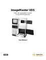
ImageMaster VDS
Video Documentation System
for Gel Electrophoresis
User Manual
80-6254-80
Edition AB
Important user information
Please read these instructions
carefully before using and of the
above prepacked columns or bulk
media
Should you have any comments on this
instruction manual, we will be pleased to receive
them at:
Amersham Biosciences UK Limited
Amersham Place
Little Chalfont
Buckinghamshire
England HP7 9NA
Amersham Biosciences
SE-751 84 Uppsala
Sweden
Amersham Biosciences Inc.
800 Centennial Avenue
P.O. Box 1327
Piscataway
NJ 08855 USA
Terms and Conditions
of Sale
All goods and services are subject to the terms
and conditions of sale of the company within the
Amersham Biosciences group which
supplies them. A copy of these terms and
conditions is available on request.
Trademarks
ImageMaster, Multiphor and PhasteGel are
trademarks of Amersham Biosciences
Limited or its subsidiaries.
AmershamBiosciences is a trademark of
Amersham plc.
Fuji is a trademark of Fuji Inc.
Windows is a trademark of Microsoft Corp.
© Amersham Biosciences AB 1998
- All rights reserved.
Contents
Contents
1. Gel Documentation System Function and Description . . . . . . . . . . . . . . .3
2. Assembly and Installation . . . . . . . . . . . . . . . . . . . . . . . . . . . . . . . . . . . .6
3. System Component Close-up . . . . . . . . . . . . . . . . . . . . . . . . . . . . . . . . . .8
3.1 Lamp controls . . . . . . . . . . . . . . . . . . . . . . . . . . . . . . . . . . . . . .8
3.2 Video camera manual controls . . . . . . . . . . . . . . . . . . . . . . . . . .9
3.3 Video camera electronic controls . . . . . . . . . . . . . . . . . . . . . . .10
3.4 Menu options displayed on the monitor . . . . . . . . . . . . . . . . . .11
3.5 Printer . . . . . . . . . . . . . . . . . . . . . . . . . . . . . . . . . . . . . . . . . . .12
4. Quick reference Guidelines . . . . . . . . . . . . . . . . . . . . . . . . . . . . . . . . . .14
5. Operating instructions . . . . . . . . . . . . . . . . . . . . . . . . . . . . . . . . . . . . . .16
5.1 Preliminary steps . . . . . . . . . . . . . . . . . . . . . . . . . . . . . . . . . . .16
5.2 UV transillumination procedure . . . . . . . . . . . . . . . . . . . . . . . .17
5.3 White light imaging procedure . . . . . . . . . . . . . . . . . . . . . . . . .19
6. Troubleshooting . . . . . . . . . . . . . . . . . . . . . . . . . . . . . . . . . . . . . . . . . .21
7. Care and maintenance . . . . . . . . . . . . . . . . . . . . . . . . . . . . . . . . . . . . . .23
7.1 Cleaning . . . . . . . . . . . . . . . . . . . . . . . . . . . . . . . . . . . . . . . . . .23
7.2 Replacing lamps . . . . . . . . . . . . . . . . . . . . . . . . . . . . . . . . . . . .23
7.3 Replacing fuses . . . . . . . . . . . . . . . . . . . . . . . . . . . . . . . . . . . . .25
7.4 Handling film . . . . . . . . . . . . . . . . . . . . . . . . . . . . . . . . . . . . . .26
7.5 Cleaning the printer . . . . . . . . . . . . . . . . . . . . . . . . . . . . . . . . .29
7.6 Printer pre-sets . . . . . . . . . . . . . . . . . . . . . . . . . . . . . . . . . . . . .32
8. Specifications . . . . . . . . . . . . . . . . . . . . . . . . . . . . . . . . . . . . . . . . . . . . .34
9. Customer service information . . . . . . . . . . . . . . . . . . . . . . . . . . . . . . . .36
9.1 Technical service and repair . . . . . . . . . . . . . . . . . . . . . . . . . . .36
9.2 Ordering informatin . . . . . . . . . . . . . . . . . . . . . . . . . . . . . . . . .36
1
2
1. Gel Documentation System Function and Description
1. Gel Documentation System Function
and Description
The ImageMaster™ VDS video documentation system is designed to quickly
and accurately document electrophoresis results. The basic system, which
includes a 312–nm ultraviolet (UV) transilluminator sample tray and an
orange lens filter, is intended for documentation of ethidium bromide-stained
agarose and polyacrylamide gels. Optional accessories such as a white light
sample tray and a blue or yellow lens filter allow documentation of
Coomassie blue and silver-stained gels as well as membranes, films, blots,
and autoradiographs. The sample area is 21x25 cm. This accommodates the
developed area of one full size Multiphor™ gel, 8 mini-gels, or up to 15
PhastGel™ gels.
The imaging system comprises a highly sensitive charged coupled device
(CCD) camera connected to a monitor, which allows viewing of the image
and manipulation of camera controls before the image is printed. This
imaging system is contained in a free-standing “dark room” that includes a
UV transilluminator as well as a white light source. Once the image is
optimized, it can be printed by the integral thermal printer. Two grades of
film are available: the higher grade Super VDS film is thermally activated
and fixed, and the regular VDS film is thermally activated and UV-light fixed.
Both use a polymer emulsion technology that produces a sharp image on
tough plastic and both have an image life of seven years under the proper
storage conditions.
If the optional LISCAP image capture software and PC board are installed on
your PC computer, the digitized image can be transferred to your PC. The
digital image is then available for analysis using, for example, the
ImageMaster Software, or for editing, annotating, or output to a printing
device used for publication.
Packing list
Main cabinet with monitor
and camera body
UV sample tray
Zoom lens assembly:
(zoom, close up 2X diopter,
and orange filter)
Power cord
Super VDS film (1 roll, plus
two shafted flanges)
Unpacking
Unwrap all packages carefully and compare contents with the list on this
page, making sure all items arrived. If any part is missing, contact your local
Amersham Biosciences sales office. Inspect all components for
damage that may have occurred while the unit was in transit. If any part
appears damaged, contact the carrier immediately. Be sure to keep all
packing material for damage claims or for repacking should it become
necessary to return the unit.
Note: Retain the sheet documenting the factory-set optimized parameters for
your system for future reference.
User manuals (3): ImageMaster
VDS, monitor (Sony), and
thermal imager (Fuji)
3
1. Gel Documentation System Function and Description
Important system information
•
Under normal operation of the ImageMaster VDS system, the
researcher is not exposed to UV light. All UV lamps automatically
turn off when any door is opened or when the sample tray is pulled
out. Pressing the BYPASS switch on the lamp control panel overrides
the safety feature for the top compartment door, however.
Prolonged exposure to UV light is harmful. If you choose to operate
the UV lamps while the top compartment is open, be sure to wear
protective clothing and UV-blocking glasses to shield yourself.
4
•
The rear panels should only be removed by trained service
technicians due to the danger of exposure to high voltage.
•
The AC power outlet must be properly grounded to protect both
personnel and the equipment.
•
All devices must be turned off before connecting to any other device
(such as a computer). Making connections with devices turned on
may damage both devices.
•
Save the documentation showing the optimized factory-set
parameters for your system. Refer to these reference parameters
should the system require resetting.
•
The camera must be initialized every time the unit is turned on or,
for best performance, at least once every 24 hours. (See section 5.1.)
•
Store film in a cool place away from sunlight.
•
If the thermal printer will not be used for an extended period (more
than one month), move the thermal head release lever down to the
RELEASE position (see Figure 10) to prevent deformation of the
rubber roller.
1. Gel Documentation System Function and Description
The top compartment contains
the camera and lens assembly,
the lamp control panel, and the
secondary power switch.
Video monitor
Camera control panel
The bottom compartment allows
access to the sample.
Printer
Removable transilluminator sample tray
Lamps Control indicator
(see Section 7.2, “Replacing
lamps” for a full description)
(The UV filter tray is standard;
the white light tray is optional)
Figure 1. ImageMaster VDS system main components
5
2. Assembly and Installation
2. Assembly and Installation
Note
Handles (ordered separately)
can be installed to facilitate
moving the unit.
The ImageMaster VDS system is assembled with the following exceptions:
the video camera lens assembly, the printer film, and the power cord. Place
the unit on a vibration-free, level surface in an area away from direct sunlight
and with relatively constant ambient temperature and humidity.
Video camera lens assembly
The lens assembly comprises a 2X diopter lens, a color filter, and controls for
the aperture, zoom, and focus. (See section 3.2 for component functions.) To
install the lens assembly:
1.
Note: The lens assembly includes an orange filter when shipped.
If the unit is to be used for white light photography of stained gels,
unscrew the orange filter and install a yellow or blue filter (ordered
separately).
2.
Open both the top and bottom compartments for better access.
3.
Unscrew the protective screw cap from the CCD video camera head
(if present).
4.
Screw the lens assembly into the CCD video camera head: we
recommend reaching up through the sample compartment so that
you can support the lens assembly with one hand while screwing it
into the video camera mount with the other hand.
Never force the assembly into the thread; finger tight installation is
enough. (Over-tightening can alter the plane of focus by changing
the camera mount position!)
Leave the lens cap in place until after camera initialization is
complete.
Load film into the thermal printer
If no film is loaded into the thermal printer, see Section 7.4, steps 1–8 to
install the provided film.
6
2. Assembly and Installation
Power connection
1.
Important: Verify that the AC power outlet is properly grounded. If
the outlet is not grounded, connect the ground terminal to an
electrical earth ground.
2.
Important: Check the voltage specification near the fuse holder for
the voltage setting. The setting must match the voltage of the power
supplied to the unit.
3.
Plug the power cable into the plug receptacle in the unit and then
plug the connector into the power socket.
Fan vents (2)
Serial number and
specification panel
D-type 25-pin connector
(for computer cable)
BNC connector
(only the right one is functional)
Fuse holder
Mains power On/Off
switch (0 = off)
Power cord receptacle
Figure 2. Rear panel The rear panel houses the mains power switch, cable connectors,
and fuse holder.
7
3. System Component Close-up
3. System Component Close-up
3.1
Lamp controls
The top compartment houses the lamp control panel, described in this
section, and the video camera CCD mount with the lens assembly, described
in the next section. To turn on the lamps, the sample tray must be in place
and all doors must be closed. Turn on the mains power switch at the rear of
the unit (l = on), and then turn on the secondary power switch on the lamp
control panel. (Depress the ON side of the switch.) A Lamps Control
indicator (to the right of the printer) indicates lamp status. “OK” indicates
that all lamps are in good working order. See the Section 7.2, “Replacing
lamps” for a key to signals indicating lamp malfunction.
Note
To prolong lamp life, all lamps
automatically switch off after
10 minutes of no detectable
activity. Lamps are reactivated as soon as either
door is opened and closed.
Lighting modes
Choose TRANS for transillumination, or lighting from below. The UV tray
automatically powers the UV lamps for UV transmittance, and the white tray
automatically lights the white lamps for white light transmittance.
Choose REFLECT for reflective lighting, or lighting from above. This mode
powers a single white lamp located at the top of the chamber. It is useful for:
1) Focusing a sample that will be transilluminated with UV because reduced
sample exposure to UV light reduces photoknicking, and 2) imaging opaque
media such as membranes.
UV light safety
Caution
If TRANS is selected and the
UV tray is installed, the UV
lamps will light when BYPASS
is pressed. Wear protective
clothing and UV-blocking
glasses to prevent exposure
to UV light.
Opening any door or removing the sample tray switches off all lamps. This
safety feature can be defeated for access to the manual camera controls in the
top compartment by pressing the BYPASS button. As long as this button is
depressed, the chosen lamps light.
Secondary power switch.
Both the mains power switch in the
back and this switch must be on.
Under normal use, leave the mains
power on and control power to the
unit with this switch.
Lighting mode selector switch
Bypass option—bypasses the safety
interlock that turns off lamps when
compartment doors are opened or the
sample tray is removed. Use with care
to avoid UV light exposure!
Figure 3. Lamp control panel
8
3. System Component Close-up
3.2
Video camera manual controls
The highly sensitive CCD video camera captures and stores the image (in 256
levels of gray) and displays it on the monitor. This image is manipulated both
manually by adjustments to the lens assembly (described in this section), and
electronically by specifying settings using the camera control panel (described
in the next section). The three lens adjustments are: aperture, zoom, and
focus.
Aperture
The aperture setting controls the amount of light that enters the CCD. The
aperture (also referred to as the f-stop) ranges from f/1.2 to f/22. Settings in
the low range (f/1.2–4) refer to the widest aperture, allowing more light to
enter. More light is required for fluorescent imaging and other low light level
applications. Higher settings (above f/8) narrow the aperture, allowing less
light to enter. Less light is required for white light imaging. Higher aperture
settings generally require longer exposure times (see the TIME menu option,
section 3.4).
Tabulated in the Quick Reference Guidelines (section 4) are starting point
apertures for imaging different gel staining methods.
Zoom
The zoom adjusts the focal length from 8–48 mm. Increasing the focal length
enlarges the image. Size the image to fill the monitor.
Focus
The focus control sharpens the image. Note: the 2.0 closeup diopter lens
must be in place for proper focusing.
Aperture adjustment
(f/1.2–22)
Zoom adjustment
(8–48 mm)
Focus
2X diopter lens
Color filter
(enhances the image; use orange
for UV imaging or the appropriate
filter for your application)
Figure 4. Lens assembly (in the top compartment)
9
3. System Component Close-up
3.3
Video camera electronic controls
The camera control panel is located under the monitor. Each function is
described below. Further manipulation options are described in section 5,
Operating Instructions.
The PRESETS keys
Five sets of parameters can be recalled by pressing the appropriate PRESETS
key. PRESET 1 is programmed at the factory for optimal UV fluorescence
imaging, PRESET 2 for white light transillumination, and PRESET 5 for
white light reflectance. All PRESETS keys can be programmed using the SET
menu option on the monitor (see section 3.4).
The SELECT keys
The arrow SELECT keys move the cursor among the menu options on the
monitor, and the + and – SELECT keys increase or decrease the displayed
value.
moves the “cursor” to the left
moves the “cursor” to the right
+ increases the value displayed
– decreases the value displayed
Figure 5. Camera control panel
The DATA key
Note
Recommended settings for
the DATA function:
gamma 1.0
B-lev
6
gain
0
Adjust the aperture and time
parameters to optimize the
image.
The DATA function is used only if the optional LISCAP or ImageMaster VDS
software and the Image Capture Board are installed on a PC computer and
connected to the ImageMaster VDS system. Pressing DATA sends the
digitized image to the external computer. While the DATA indicator lamp is
lit, the monitor may appear blank or noisy during the data transfer. Under
Windows 3.1, Windows 95 or 98, the data transfer take one second. Under
Windows NT, the data transfer can take up to 20 seconds.
The STILL key
The STILL function captures the most recent image in the camera memory
and displays it on the monitor. Once the STILL key is pressed, the indicator
lamp lights and the camera stops collecting video information. To resume
collecting image data, press the STILL key again. The STILL indicator lamp
is not lit when the image on the monitor is displaying real-time information.
10
3. System Component Close-up
3.4 Menu options displayed on the monitor
As long as the camera is active (i.e., it is sending images to the monitor
because the STILL key has not been pressed), camera settings can be
manipulated to optimize the image before sending it to the printer or the
optional software. Setting guidelines are listed in the Quick Reference
Guidelines (section 4). Setting descriptions follow:
SET
Programs the four settings described below into a program
memory keys 1–5). Once parameters are selected, move the
cursor to “set” and press the desired memory location (one of
keys 1–5) for 5 seconds.
TIME(S)
Shows the camera integration time, or exposure, in seconds.
There are 70 selectable times ranging from 1/10,000 to 10 s.
The time value “wraps around,” increasing or decreasing by a
small increment except at the end values, where increasing from
10 s results in the lowest value 1/10,000, and decreasing from the
lowest value results in 10 s, or the highest value.
When adjusting the time value, keeping the arrow key depressed
accelerates scrolling through the values.
GAIN
Controls the level of white. “Auto” selects the lightest area and
compares it to a pre-set white level for optimum contrast.
Selectable increments range from 0–9.
The 0 setting shows raw data, and is recommended especially for
data sent to a computer for analysis. (Try adjusting the time and
aperture settings before adjusting the gain.)
B.LEV
(or black level) controls the dynamic range of the voltage signal
(which affects CCD sensitivity). “Auto” selects the darkest area
and compares it to a pre-set black level for optimum contrast.
The recommended starting setting for both UV and white light
imaging is 6. Selectable increments range from 1–9. Any setting
other than 6 decreases the sensitivity of the collected information,
but increases the contrast.
Gamma
Controls the linearity of the CCD.
The gamma correction setting should be set to 0.45 for viewing
the sample on the monitor and printing the image with the
thermal printer. It should be set to 1.0 if the image is sent to a
computer.
11
3. System Component Close-up
3.5
Printer
Printer parameters are preset for ImageMaster VDS system applications, and
Super VDS film is already loaded. To print an image, press the PRINT key.
Film types and film loading
Two types of film are available. The high-grade Super VDS film is installed at
the factory, and the printer is set to process this thermally fixed film. The
regular-grade film is UV fixed, so the “Film Select” setting must be adjusted
if switching film type. Section 7.4 “Handling film” describes how to load
new film, and step 9 describes changing the Film Select setting.
Latch to open and close the front panel
(for film loading and roller cleaning)
Printer power switch
Press the PRINT key for a print of the
image displayed on the monitor
The LED displays print
number or the printer
settings if using the
FUNC keys.
Slide the stacking tray into this
slot, holding the tray level. When
properly installed, the tray snaps
into place with a click.
Figure 6. Thermal printer functions
12
Press the REPRINT key for additional
copies of the image displayed on the
monitor. The same ID information is
printed on each reprint.
The FUNC key accesses
all printer settings.
The arrow keys
increase or decrease
the value displayed
on the LED.
3. System Component Close-up
Printer function quick reference
•
To print, press the PRINT key. Prints are numbered sequentially and
the current print number displays when the printer is in standby
(ready) mode; pressing the PRINT key again, increases the print
number by 1.
•
To print an identical image multiple times, press the REPRINT key.
This produces the last image stored in printer memory (which may
be different from the image on the monitor if the camera has
collected data of a new image.)
•
Pressing PRINT and the ▲ key resets the print number to 0.
Printer notes
•
Turning the power off clears the printer memory.
•
Allow about 30 seconds between prints for optimum print quality.
•
During the printing process, the printer is not available to execute
additional commands. The LED will display “P.”
•
If the printer will not be used for one month or more, release the
thermal head to prevent deformation of the rubber roller. (See section
7.4, “Loading a roll of film” step 3, and also Figure 10.)
•
To clear a film jam, refer to section 7.5 .
•
When the roll is nearly used (10 prints or fewer remaining), a printer
alarm sounds and the LED displays “END.” See section 7.4 for film
loading instructions.
•
If using the regular grade UV-fixed film, the UV fixing lamp stays lit,
even when the printer is not printing. If the lamp goes off because the
unit has not been activated for 2 hours, turn the printer off then on
to reset the lamp.
•
The factory settings for the printer are listed in Section 7.7 for
13
4. Quick Reference Guidelines
4. Quick Reference Guidelines
1
Place the sample on the appropriate sample tray and install the tray.
2
Initialize the camera.
3
Size and focus the image in REFLECT mode.
4
Select the light mode (TRANS for transillumination or REFLECT
for lighting from above).
5
Set the electronic camera controls. (Or, select the appropriate
PRESETS key)
6
Print the image on the thermal printer by pressing the PRINT key on
the printer or send the digital image to an external computer by
pressing the DATA key.
Standard Settings
Gel staining method
EtBr
Coomassie
Silver
Manual controls
Light tray
Lamp control mode
Lens assembly
Filter
Aperture (f/stop)
UV
Trans
White
White
Reflect or Trans Reflect or Trans
Orange
4
Yellow
22
Blue
16
1
2
5
~1.8
0
6
0.45
0.07
0
6
0.45
~0.2
0
6
0.45
Electronic controls (Camera control panel)
Preset key
Camera settings
Integration time (s)b
Gain
B-Lev
Gamma
The numbered keys on the camera control panel are factory-set shortcut keys that set the
electronic video settings to the optimal settings for the gel type. These keys can be
programmed to other settings.
The optimal integration time for each system is determined at the factory. Refer to the sheet
that accompanied your ImageMaster VDS for initial settings.
14
4. Quick Reference Guidelines
Using the ImageMaster VDS as a quantitative tool
The most accurate method to quantitate an unknown sample is to load
multiple aliquots of several dilutions of the sample, alternating lanes with
well characterized standards which are as similar as possible to the unknown
in composition and size. Comparing samples side-by-side with standards on
the same gel minimizes effects of uneven illumination, differences in gel
concentration, pH, stain concentration, temperature and other experimental
variation, all of which may affect fluorescence or absorbance by the samples.
Measuring at several concentrations assures that some of the samples will fall
in the linear region of the system response.
To assure consistency from gel to gel and day to day, establish and adhere to
a well-defined procedure for gel and sample preparation, standard
characterization, sample and standard loading, electrophoresis conditions
(voltage or current), staining and destaining, position on the light table,
image magnification, and camera settings for both the lens and electronic
parameters.
15
5. Operating Instructions
5. Operating Instructions
5.1
Preliminary steps
Place the sample and install the sample tray
Note
The bottom compartment door
must be open in order to install
or remove the sample tray.
16
1
Open the bottom compartment door to gain access to the sample
tray. Select the required tray. The basic system includes a 312–nm
UV transilluminator tray. An optional white light sample tray can be
ordered separately.
2
Place the sample on the tray. (It is easiest to place the sample before
installing the tray, but the sample can also be placed with the tray
already in place.)
If the gel is wet, take care to not trap any air pockets or bubbles
beneath it, as they will interfere with image clarity.
If the gel is dry, make sure the surface is flat. This can be
accomplished by placing a glass plate over it or laying weighted
strips along the sides.
3
To install the tray: Position it, with the front edge slightly tilted up,
so that the sample tray rollers engage with the roller tracks. Insert
the drawer rollers into the track and lower the tray slightly. The tray
functions like a drawer—close it completely.
5. Operating Instructions
Important!
Initialize the camera
The camera must be initialized
every time the system is turned
on in order for the CCD to be
properly mapped.
1
Important! The camera must be initialized every time the system is
turned on or a minimum of once every 24 hours in order for the
CCD to be properly mapped. The CCD requires complete darkness
for this operation. The recommended way to accomplish this is to
install the lens cap. (Alternatively, turn the aperture control to f/22.)
2
Install a sample tray, close all doors, and turn the mains power on.
3
Initialization requires 10–15 seconds. During initialization, “Please
wait for initialization” appears on the monitor and the Lamps
Control indicator flashes the signal “OK”. If the message “Please
make sure all the doors are closed” appears instead, close all the
doors to continue.
Note
If an external computer is
connected to the ImageMaster
VDS system, first initialize the
camera, and then turn on the
computer.
Initialization is complete when BOTH “Please wait for
initialization” disappears from the monitor and the Lamps Control
indicator signal “OK” remains lit (stops flashing).
To initialize, install the lens cap
(recommended) or set the
aperture to f/22.
Close all the doors. Then turn the
mains power switch on.
Figure 7. Initializing the camera
5.2
Caution
Exposure to UV light can
cause serious damage to eyes
and skin. Cover your skin and
wear UV-blocking glasses.
UV transillumination procedure
1
Follow the preliminary steps in the previous section: Make sure you
have chosen the UV sample tray, that the sample is in place, and that
the tray is properly installed.
2
Verify that the video camera is initialized, and the orange filter is
installed on the camera lens (for ethidium bromide-stained gels).
Set the camera aperture to f/1.2 (maximum opening).
3
Switch the main lamp control switch on the lamp control panel to
ON, and choose REFLECT for initial image focusing. The top
compartment door must remain open while you adjust the camera
zoom and focus. To switch on the light while the door is open, you
17
5. Operating Instructions
must press the BYPASS switch on the lamp control panel
continuously. Adjust the zoom and focus until the image is properly
sized and sharply focused.
Note: If the UV tray is in place and the TRANS mode is selected,
pressing BYPASS turns on the UV lamps. This is not recommended
for focusing. Use the REFLECT mode, without UV light. A ruler
beside the gel is a convenient focusing target.
4
Close the compartment door once these adjustments are satisfactory
and select TRANS.
5
Fine-tune the electronic camera controls using the camera control
panel. The recommended starting point settings are:
B-lev
6
Gain
0
Gamma 0.45 for video and printer images or 1.0 for
transfer to a computer
Unless the settings have been reprogrammed, PRESET 1 is factory
set for optimal UV imaging.
Note
Adjust only one parameter at a
time, and only by small
increments.
Note
6
7
If no activity is detected for
10 minutes, the lamps
automatically shut off. To
reactivate, open and close either
door.
First optimize aperture and time settings, and if further image
adjustment is required, try incrementally increasing the gain
(default=0) or decreasing the B-lev (default=6).
Note: Changing the B-Lev setting may reduce the dynamic range;
for instance, decreasing the value removes part of the signal. This
could be useful in removing background “noise.”
Once the image is optimized, press the STILL key to hold and
display on the monitor the image currently stored in camera
memory.
Note: Pressing the STILL key stores the image so that the sample
can be removed from the UV tray to minimize photoknicking.
Pressing the STILL key stores the information, but is not necessary
to send the image to the printer or computer.
The image may be captured by
pressing STILL or DATA
before the lamps switch off.
8
Print the image by pressing the PRINT key on the thermal printer.
While printing, the printer displays "P" and does not accept further
commands. Once the print number appears, the printer is ready to
produce another print.
Note: The printer prints the image on the monitor at the time the
PRINT key is pressed. For a record of the video settings, press
PRINT while the setting menu is on the monitor. The setting menu
can be recalled by pressing any cursor key.
To send the image to a computer running the (optional) LISCAP
software, press the DATA key. Note: The video settings cannot be
sent to the computer.
18
5. Operating Instructions
5.3 White light imaging procedure
1
Follow the preliminary steps in section 5.1: Make sure you have
chosen the white sample tray, that the sample is in place, and that the
tray is properly installed.
2
Verify that the video camera is initialized and that the appropriate
filter is installed on the lens assembly. Set the camera aperture in the
smaller aperture range, starting with f/22 for reflectance and slightly
larger (lower f/stop) for transillumination.
3
Switch the main lamp control switch on the lamp control panel to
ON, and choose REFLECT for initial image focusing.
4
Size and focus the image: The top compartment door must remain
open while you adjust the camera zoom and focus. To switch on the
light while the door is open, you must press the BYPASS switch on
the lamp control panel continuously. Adjust the zoom and focus until
the image is properly sized and sharp. Close the compartment door
once adjustments are final.
5
Select the final imaging light mode: TRANS or REFLECT. Close all
doors. The image should appear on the monitor.
6
Fine-tune the electronic controls using the camera control panel. The
recommended starting point settings are:
B-lev
Gain
Gamma
6
0
0.45 for output to the printer or 1.0 for
output to computer
Unless the settings have been reprogrammed, PRESET 2 is factory set
for optimal white light transillumination, and PRESET 5 is factory
set for optimal white light reflectance.
Note
7
First optimize aperture and time settings, and if further adjustment is
required, try incrementally increasing the gain (default=0) or
decreasing the B-lev (default=6).
Note: Changing the B-Lev setting may reduce the dynamic range; for
instance, decreasing the value removes part of the signal. This could
be useful in removing background “noise.”
8
Once the image is optimized, press the STILL key to hold and display
on the monitor the image currently stored in camera memory.
Note: Pressing the STILL key stores the image so that the sample can
be removed from the UV tray to minimize photoknicking. Pressing
the STILL key stores the information, but is not necessary to send the
image to the printer or computer.
Adjust only one parameter at a
time, and only by small
increments.
19
5. Operating Instructions
Note
If no activity is detected for
10 minutes, the lamps
automatically shut off. To
reactivate, open and close
either door.
The image may be captured by
pressing STILL or DATA
before the lamps switch off.
20
9
Print the image by pressing the PRINT key on the thermal printer.
While printing, the printer displays "P" and does not accept further
commands. Once the print number appears, the printer is ready to
produce another print.
Note: The printer prints the image on the monitor at the time the
PRINT key is pressed. For a record of the video settings, press
PRINT while the setting menu is on the monitor. The setting menu
can be recalled by pressing any cursor key.
To send the image to a computer running the (optional) LISCAP
software, press the DATA key. Note: The video settings cannot
be sent to the computer.
6. Troubleshooting
6. Troubleshooting
No indicator lamps light and the monitor remains blank
Check the power source and connections
1
2
3
Check that the power cord is plugged into a working electrical outlet.
Check the power cables for loose connections.
Check the fuses. Replace if they are damaged.
Lamps don’t turn on
1
2
3
Check that both the mains power switch (on the back panel) and the
secondary power switch (in front, top compartment) are ON.
If the Lamps Control indicator shows a lamp failure, replace the
indicated lamp. (See Section 7.2, “Replacing lamps.”)
Lamps automatically shut off after 2 minutes of inactivity. To
reactivate, open and shut either compartment door.
Power indicator lamps are lit but the monitor remains blank
1
2
3
4
5
Check that the sample tray is properly installed.
Check that both doors are closed and the lens cap was removed from
the lens assembly after initialization.
Check the UV or white light lamps by pressing BYPASS.
Increase the aperture to allow more light to enter the camera. Try
opening it completely (f/1.2), then decreasing the aperture
incrementally as required.
The camera must be initialized each time the mains power is turned
on and at least once every 24 hours. To initialize, be sure the lens cap
is in place or set the aperture to f/22 and close all the doors
(See section 5.1).
Unclear or no image on the monitor
Camera variables
1
2
3
4
Initialize the camera by switching the mains power off and then on
(see section 5.1). No light must enter the lens during initialization, so
be sure the lens cap is in place (or that the aperture is set to f/22) and
all doors are closed. Be sure to remove the lens cap after initialization
is complete.
For the zoom lens to be able to focus, the close-up diopter lens (2X)
must be in place. See section 3.2 for a lens assembly diagram.
Make sure the camera lens, filter, and CCD camera mount are free of
foreign materials. Clean with lens paper if required.
If the camera mount position has changed (due, for example, to overtightening the camera lens), the plane of focus may be out of range.
Contact the Technical Service Department for advice.
21
6. Troubleshooting
Monitor and lamp variables
1
2
3
Check that the monitor is displaying the image currently in camera
memory—the STILL indicator lamp should be OFF.
Lamps automatically shut off after 10 minutes of inactivity. To
reactivate, open and shut either compartment door.
Check that all lamps are functioning. Replace as required
(see section 7.2).
Sample variables
1
2
3
Make sure the sample is completely flat against the sample tray.
Flatten dry samples by placing a glass plate over them or placing
weighted strips along the side.
Remove any bubbles under wet gels.
Printer
No film emerges upon pressing the print key
1
2
Turn the printer power OFF. Check that film is properly loaded.
If the printer is out of film, reload. (See section 7.4)
Printer output is spotted
1
Send a cleaning sheet through the printer to clean the thermal head
after every 100 prints. (See section 7.6.)
Film jams
1
Check that the stacking tray is properly installed. To install, slide it
into the stacking tray slot, holding the tray level; it should snap into
place with a click.
Film quality
1
2
Check printer settings; there are two film types, and the proper
setting must be programmed. (See section 7.4, step 9.)
Store film in a cool, dark place to preserve film quality.
Error messages
1
2
22
Reset the printer by turning the printer power switch off
and then on.
Refer to the separate FUJI™ film Thermal Imager Instructions
accompanying the ImageMaster VDS system. The error code key
is on page 16.
7. Care and Maintenance
7. Care and Maintenance
7.1 Cleaning
Unit body
Use a soft cloth dampened with water or a mild cleaning solution to clean the
cabinet and display.
Sample trays
Wipe the sample tray after each use to remove all residual materials. Use only
a damp cloth and a mild cleaning solution. Do not mar the sample tray
surface by cutting gel on it or scraping gel away.
Lens and lens filters
The CCD camera mount, closeup diopter lens, zoom lens, and the filter must
all be clean because any foreign material will reduce image quality.
Periodically check for dust and dirt and clean with only professional quality
lens cleaner and lens cleaning paper. Never over-tighten any lenses to prevent
moving the camera mount, which may result in altering the plane of focus.
7.2 Replacing lamps
Lamps Control indicator
The Lamps Control indicator electronically monitors lamp output. A lamp
typically provides 500 hours of service. A lamp failure is indicated by both a
single lit lamp under the “Lower” and “Upper” row, and by a row of lamps
lit horizontally in the L1 to L4 field. An example is illustrated below. In case
of failure, replace the indicated lamp.
Refers to the ultraviolet (UV) and
white light (WL) lamps in the
lower compartment, under the
transilluminator.
Refers to the white light (WL)
lamp in the upper
compartment, behind the
camera lens assembly.
Example
If this single lamp
lights as well as the
row of lamps to the
left of L4, replace the
UV lamp in the lower
compartment, at the
rear of the unit.
L1 through L4 refers to
lamp sets numbered
from the front to the rear
of the compartment.
Figure 8. Lamps Control indicator
23
7. Care and Maintenance
UV lamps
Required: 8 W, 312 nm UV lamp. Code no. 80-6249-45.
To replace a lamp:
1
Important: Turn the mains and secondary power switches off and
disconnect the power cord from the mains power.
Note
If one or more lamps are
burned out due to age, all
lamps should be replaced at
the same time to ensure even
light intensity.
2
Remove the sample tray and open the lower compartment door.
Note the four lamp pairs, each pair labeled: one UV lamp, and one
white light lamp.
3
Remove the malfunctioning lamp by carefully rotating it about ⁄-turn
counter-clockwise until the pins align vertically. Carefully pull the
lamp upward.
4
To insert the new lamp, hold it so that the metal pins align vertically.
Place the lamp in the sockets at each end of the unit and lightly push
it into place. Rotate the tube about ⁄-turn clockwise until it locks into
place.
White light lamps
Required: 8 W white light lamp. Code no. 80-6249-29.
To replace a lamp:
1
Important: Turn the mains and secondary power switches off and
disconnect the power cord from the mains power.
24
2
Remove the sample tray and open the lower compartment door.
Note the four lamp pairs, each pair labeled: one UV lamp, and one
white light lamp.
3
Remove the malfunctioning lamp by carefully rotating it about ⁄-turn
counter-clockwise until the pins align vertically. Carefully pull the
lamp upward.
4
To insert the new lamp, hold it so that the metal pins align vertically.
Place the lamp in the sockets at each end of the unit and lightly push
it into place. Rotate the tube about ⁄-turn clockwise until it locks into
place.
7. Care and Maintenance
7.3
Replacing fuses
Fuses protect equipment by disconnecting loads too large for the instrument's
circuit design. For continued protection, replace only with fuse of the
specified voltage and current ratings. The fuse holder above the mains power
cord receptacle holds two 250 V fuses:
110–120 V~, 60 Hz (US model) fuses (2): F 4A, 250V
220–240 V~, 50 Hz (European model) fuses (2): F 2.5A, 250V
100 V~, 50/60 Hz (Japanese model) fuses (2): F 4A, 250V
1
Caution! Turn the mains and secondary power switches off and
detach the power cord before replacing fuses.
2
Insert a small flat-blade screwdriver into the slot on the fuse holder,
depress, and pull the holder door forward.
3
Pull the fuse out of its holder and inspect. If the fuse element is
burned or broken, replace the fuse with an identical type. If the fuse
appears to be intact, check it with an ohmmeter.
4
Insert a good fuse into the holder and press the holder door shut.
Fuse holder
Figure 9. Mains power module
25
7. Care and Maintenance
7.4
Note
Keep film away from direct
sunlight during loading.
Always store film in a cool,
dark place.
Handling film
Loading a roll of film
This section describes how to install a new roll of film when no film is
currently installed or when the film roll is empty. To switch to a different type
of film, first remove the installed film by following the instructions in the next
subsection “Removing a roll of film.”
Important: Note the type of film you are installing. Super VDS film is included
with the unit, and the printer is originally set to “LCr” to process it. Regular
VDS film can be ordered, and if used, the setting must be changed to “TFF”
(see step 9).
1
The VDS mains power switch
must be on (I), the secondary
power switch must be
switched to ON, and the
printer power switch must
be on.
2
Release the printer cover by
pressing the Push button on
the upper left corner.
3
Move the thermal head
release lever down to the
RELEASE position.
4
Lift the film roll out of
the holder rails. Remove
the flanges from
both ends of the spool
and insert them into the
new roll of film.
5
Figure 11. Loading a new roll of film
Seat the ready film
spool into the
holder rails. Once
the spool seats,
the rubber roller
will start rotating.
Guide the film to
the back of the
compartment and
gently press the
middle of the spool
just until the film
starts to selffeed.
Figure 12. Feeding the film through the roller
Note
Cleaning the thermal head after
each roll of film is a recommended preventative maintenance
measure. See section 7.5
“Cleaning the printer, Thermal
head” for the procedure, which
is easily performed when
changing film.
26
Figure 10. Removing an empty roll of film
7. Care and Maintenance
6
Allow the film to feed until it emerges at the stacking tray and then
stop the roller by lifting the thermal head release lever into the
PRINT position.
7
Close the front cover.
8
Optional: Reset the
counter to zero by
simultaneously
pressing the ▲ and
PRINT keys. (Each
film roll will produce
170 records at the
default 4:3 aspect
ratio setting.)
9
Figure 13. Closing the printer cover
If you are switching to a different film type, change two settings as
follows:
Film select setting
9.1.a. When the printer is in normal, or standby state (showing the
print number), press the ▼ key and then also the FUNC key. This
will switch to a submenu in which 6 parameters can be set.
9.1.b. Forward through the menu 5 steps by pressing the FUNC key
until either LCr (required setting for Super VDS film) or TFF
(required setting for VDS film) appears. Press either ▼ key or the ▲
key to toggle between the two choices. Press and hold the FUNC key
for longer than 0.5 s to set the current value and exit.
Tone setting
9.2.a. When the printer is in normal, or standby state (showing the
print number), press the FUNC key to enter the “Print mode”
submenu.
9.2.b. Forward through the menu 3 steps by pressing the FUNC key
until either T3 (recommended setting for Super VDS film) or T7
(recommended setting for VDS film) appears. Please note that the
setting that results in the closest approximation of the image on the
monitor may vary slightly from these values.
9.2.c. Press either ▲ key or the ▼ key to scroll through the tone
setting options until the desired setting appears. Press and hold the
FUNC key for longer than 0.5 s to set the current value and exit.
27
7. Care and Maintenance
Removing a roll of film
Important: Allow the printer to rewind the film; never pull the film out
while the printer power is ON or while the lever is in the PRINT position.
1
Set the printer to service mode: The ImageMaster VDS mains power
switch must be ON (I), the secondary power switch must be ON,
and the printer power switch must be OFF. Simultaneously hold
down both the PRINT and FUNC keys and turn the printer power
switch ON. The LED will indicate “SEV.”
2
Release the printer cover by pressing the PUSH button on the upper
left corner of the cover.
3
To rewind the film, press the FUNC key. If necessary, apply gentle
pressure to the film drum to help feed the film at the proper rate.
The LED will indicate “PrU” (Printer unwind). Once the film edge
is free, release the FUNC key.
4
If loading a new roll of film: Go to step 3 of section 7.4 “Loading
a roll of film.”
If cleaning the printer roller, go to step 2 of section 7.5 “Rubber
roller.”
If cleaning the thermal head, go to step 2 of section 7.5
“Thermal head.”
Clearing a film jam
Important: Allow the printer to rewind the film; never pull the film out
while the printer power is ON or while the lever is in the PRINT position.
Note
It is advisable to clean the
roller after a jam to remove
particles that may streak the
film. (See section 7.5.)
1
The VDS mains power switch must be on (I), the secondary power
switch must be switched to ON, and the printer power switch must
be ON. Release the printer cover by pressing the Push button on the
upper left corner.
2
Inspect the spool for proper placement, the film path for
obstructions, and the film for signs of bunching or buckling.
To remove a damaged section of film, lower the thermal head release
lever into the RELEASE position and allow the roller to advance the
film into the stacking tray. If the printer is unable to feed the film, try
rewinding the film:
a. Return the lever to the PRINT position and switch the printer
power OFF.
b. Simultaneously hold down both the PRINT and FUNC keys and
turn the printer power switch ON. The LED will indicate SEV. Note:
If a section of film is stuck in the exit, pressing the ▼ key in the SEV
mode will trim it off.
28
7. Care and Maintenance
c. To rewind the film, apply gentle pressure to the film drum (to help
feed the film at the proper rate) and then press the FUNC key to
start rewinding. The LED will indicate “PrU” (Printer unwind).
Once the film is free, release the FUNC key. Move the thermal head
release lever down to the RELEASE position. Reload the film
according to instructions in section 7.4 “Loading a roll of film,”
steps 5 to 7.
If the roller is still unable to feed the damaged film, turn the power
to the printer OFF and lower the lever into the RELEASE position.
Lift the roll of film out and slowly but firmly pull the film free of the
roller. Once the film is free, cut off the damaged section. (It may be
easier to reload the film if you angle the cut slightly.) Turn the
printer power back ON. Reload the film according to instructions in
section 7.4 “Loading a roll of film,” steps 5 to 7.
7.5
Cleaning the printer
Rubber roller
White vertical lines or black spots on your prints may indicate that the
rubber roller and/or the thermal head require cleaning. If cleaning doesn’t
improve the photo quality, contact a qualified service technician to replace
the thermal head or roller.
1
Remove the film according to the instruction in section 7.4
“Removing a roll of film.”
Figure 14. Cleaning the roller
2
3
Turn the printer power OFF and then ON to reset the printer mode.
The LED will indicate error condition 1 and an audible beep will
sound.
Moisten a cotton swab with water to clean the roller—do not use
gauze or cloth because they may catch in the roller!
29
7. Care and Maintenance
4
Press the REPRINT key to start the rubber roller rotating. It will
rotate for about 30 seconds. (The LED will first indicate error 1 and
then cleaning mode CL1.) Clean the roller with the cotton swab as it
rotates.
Once the roller stops, the printer will again display the error 1
message. If the roller is not sufficiently clean, repeat step 4.
5
Allow the roller to dry.
6
Move the thermal head release lever into the RELEASE position.
7
Reload the film as
described in section 7.4
“Loading a roll of film,”
steps 5 to 7.
Thermal head
It is good practice to run the
cleaning sheet after every roll of
film to prevent printing quality
problems such as blotches and
streaks. The maximum
Figure 15. Cleaning the thermal head
recommended interval between
cleaning sheet runs is three rolls of film (approximately 500 prints).
Use only the accessory cleaning sheet to clean the thermal head!
1
Remove the film according to the instruction in section 7.4
“Removing a roll of film.”
2
Lift the roll of film out. Turn the printer power OFF and then ON to
reset the printer mode. The LED will indicate error condition 1 and
an audible beep will sound.
3
Make sure the thermal head release lever is in the PRINT position.
4
Note the instructions on the cleaning sheet: Do not touch the
cleaning section of the sheet, be sure to insert the sheet with the
cleaning surface facing up (the printed side of the sheet will be
against the rubber roller and the matte side will contact the thermal
head), and take care to align the sheet.
To feed properly, the positioning line printed on the cleaning sheet
should align along the entire length of the edge just above the rubber
roller. Proper alignment requires that the sheet be even so that it
won’t skew as it feeds, and that the sheet be making contact with the
rubber roller for a firm grip; gently edge the sheet down as far it will go.
30
7. Care and Maintenance
5
Simultaneously press the FUNC and ▲ keys. The cleaning sheet will
advance but not pass all the way through. As the sheet advances, the
LED will switch from indicating error 1 to indicating cleaning mode
CL3.
If the cleaning sheet does not begin to feed, move the thermal head
release lever to the RELEASE position and reposition it.
When the cleaning sheet begins to enter the stacking tray, an audible
beep will sound and the LED will display cleaning mode CL2. Move
the thermal head release lever to the RELEASE position. The printer
will then eject the cleaning sheet and the LED will first display
cleaning mode CL1 and then error 1 for about 30 seconds.
If the sheet becomes stuck because it engaged with the roller too late,
turn the power to the printer OFF and lower the thermal head
release lever into the RELEASE position. Slowly but firmly pull the
sheet free. Go back to step 3.
6
Repeat steps 3 to 5 as often as required.
7
To reload the film, see section 7.4, Loading a roll of film, steps 5 to 7.
31
7. Care and Maintenance
Menu available by pressing FUNC key only
(PRINT mode)
Brightness
Contrast
Tone
Gain select
Gain
b0*
C0*
T3 (Super VDS film) or
T7 (Regular VDS film)
G_n
G28
*The available range for these settings is -9 to 9.
However, 0 is the default (and nominal) setting,
and settings outside the -3 to 3 range are not
recommended.
Menu available by pressing both the FUNC and
the ▲ key simultaneously (FUNCTION Mode 2)
Aspect
Int/Noint
Odd/Even
Mono/color
Signal select
Film select
7.6
A43
in
odd
Cro
S_A
LCr (Super VDS film) or
TFF (Regular VDS film)
Menu available by pressing both the FUNC
and the ▼ key simultaneously
(FUNCTION Mode 1)
Output
Enhance
H-size
Format
H-posi
V-posi
THr
EoF
5_0
F10
HOC
UOE
Menu available by pressing the FUNC, ▲,
and ▼ keys simultaneously
(First set the LED display for S3 with the
▲ and ▼ keys and then press FUNC to
access FUNCTION Mode 3)
Direction
Posi/Nega
Film cutsize
Cutter
Mirror
Gradation
d0
PoS
C_n
Con
obu
G_8
Menu available by pressing the FUNC, ▲, and
▼ keys simultaneously
(First set the LED display for S4 with the ▲ and
▼ keys and then press FUNC to access
FUNCTION Mode 4)
Menu available by pressing the FUNC, ▲,
and ▼ keys simultaneously
(First set the LED display for S5 with the
▲ and ▼ keys and then press FUNC to
access FUNCTION Mode 5)
LED display select
Print no. print
T/H temp print
EPDT
VSDT
Filter select
ID print
ID character set
d50
Con
ToF
9A8
5Cd
5F1
Pon
050
Note
The 16 available characters are programmed
to spel "Amersham Biosciences” at the factory.
To reprogram, see the next section or the Fuji
Thermal Imager instructions.
Printer pre-sets
Printer parameters are preset for ImageMaster VDS system applications.
The factory set parameters for the system are listed below for your reference.
Note: The settings in bold are for Super VDS film. (See Section 7.4,
“Loading a roll of film” step 9, for instructions on how to change film type
settings.)
Restoring default printer parameters
If the printer settings are in an unknown state, restore default parameters
according to the instructions below. For a full description of all printer
options and settings, see the Fuji Thermal Imager instructions accompanying
your ImageMaster VDS system.
1
32
To initialize all printer parameters, hold down both the ▼ and
PRINT keys while turning the printer mains power switch ON.
7. Care and Maintenance
2
After printer initialization (step 1), each print will be labeled “FUJI
FILM”. To program the 16-character label to read
“APBiotech,” follow the procedure below. For additional codes to
program your preferred text, refer to the FUJI manual.
a Press the FUNC key while
holding down both the ▲ and
▼ keys to access “FUNCTION
Mode 3”. Then select “S5”
(FUNCTION Mode 5) by
pressing the ▲ key twice.
b Press the FUNC key two times
to access the ID character set.
The position (0) and character
(46) code for “F” in FUJI FILM
will appear: 046.
Codes for a “APBiotech”
label on each print
Character
A
P
B
i
o
t
e
c
h
position / character
code
0
1
2
3
4
5
6
7
8
41
50
42
69
67
74
65
63
68
c In this position, use the ▲
and ▼ keys to select the desired
character code for the first (0)
position. For A, the code should
be 041, as shown in the table.
Press the FUNC key to accept. The next set of character codes
automatically appears. The table lists all position and character
codes required to program “APBiotech.”
d Press the FUNC key for more than 0.5 s to set the selected values
and exit.
3
Check that the film type setting matches the film type in the printer
(section 7.4, step 9).
4
To match the print to the monitor image, follow the procedures in
section 5.2 for UV transillumination imaging or section 5.3 for white
light imaging.
33
8. Specifications
8. Specifications
ImageMaster VDS system
Voltage
Power consumption
Operating environment
System timer
I/O ports
Dimensions
110–120 V~, 60 Hz (US model)
fuses (2): F 4A, 250V
220–240 V~, 50 Hz (European model)
fuses (2): F 2.5A, 250V
100 V~, 50/60 Hz (Japanese model)
fuses (2): F 4A, 250V
300 VA Max.
10–40 °C
Relative Humidity: 0–90%
noncondensing
Indoor use, pollution degree 2,
Overvoltage category II
Non Operating Environment:
-10–60 °C, relative humidity 95% max.
Lamps shut off after 10 minutes of
inactivity. Open and close either door
to reactivate.
Composite video signal, 1.0 Vpp at
75 ohm, BNC connector
25-pin D-type male parallel
communication port
645 mm (H) x 528 mm (W) x 3
90 mm (D)
Video System
Number of pixels
System type
Scanning system
Minimum illumination
Electronic shutter
Gain control
Resolution
Signal to noise ratio
Gamma correction
Frame store
Video output
Power supply
Safety
Power consumption
34
795 (h) x 596 (v) (US and Japanese
models)
811 (h) x 508 (v) (European model)
NTSC (US and Japanese models)
PAL (European model)
2:1 Interlace
0.2 Lux at f/1.2 & shutter speed 1/50;
0.0004 Lux at f/1.2 with 500 fields
integration
1/100 sec PAL or 1/120 sec NTSC up
to 10 sec.
Auto black restoration or manual
selectable
More than 570 horizontal TV lines
More than 46db with AGC off
0.45 or 1.0, selectable
STILL function button with
field/frame selection
Composite video signal, 1.0 V pp at 75 ohm
85 to 264 V~ at 47Hz to 440Hz, automatic
IEC601/UL544 approved
12 W
8. Specifications
Printer
Recording system
Fuji thermal film
Number of prints
Resolution
Gray levels
Imaging mode
Aspect ratio
Image memory
Thermal
VDS Film, 101 mm (W) x 14 m (L)
Super VDS Film, 101 mm (W) x
14 m (L) Print cycle time: 17–20 s
170 (standard size, portrait, 1:1),
140 (long size, landscape, 4:3)
Pixels 6.73 dots/mm, elements
13.46 dots/mm
Selectable 256, 64, 32 or 16
Selectable positive or negative mode
Selectable 1:1 or 4:3
One frame image memory
incorporated
Transilluminator sample trays
Analytical area
Working area
18 x 23 cm
21 x 25 cm
Transilluminator lamps
UV lamps: 8 W, 312 nm, 4 lamps
White light lamps, 8 W, 5 lamps
PC options
Image capture board
LISCAP image
capture software
LISCAP NT Driver
Image capture kit
ImageMaster TotalLab
8-bit board to allow transfer of the
digital camera image data to an IBM
PC type computer
Data image capture software for the
PC operating under Windows™
(image capture board required).
Drivers for the Image capture kit under
Windows NT 4.0 only.
Data capture board and LISCAP
software
Data capture and analysis software for
the PC operating under Windows 95,
98 and NT 4.0 (image capture board
required).
Product Certifications
Safety
Emissions
Immunity
Marking
EN60950
EN55022 (or equivalent documented
standard)
IEC 801-2, IEC 801-3, IEC 801-4
CE mark
This declaration of conformity is only valid for the instrument when it is:
•
used in laboratory locations,
•
used as delivered from Amersham Biosciences except for
alterations described in the User Manual, and
•
connected to other CE labeled instruments or products recommended
or approved by Amersham Biosciences .
35
9. Customer Service Information
9. Customer Service Information
9.1
Technical Service and Repair
Amersham Biosciences offers complete technical support for all our
products. If you have any questions about how to use this product, or would
like to arrange to repair it, please call or fax your local Amersham Biosciences
representative.
Important: Request a copy of the Amersham Biosciences “Health
and Safety Declaration” Form before returning the item. No items can be
accepted for servicing or return unless this form is properly completed.
9.2
Ordering information
ImageMaster VDS system
Qty.
Code no.
Each unit includes: Main body, UV tray, 8–48 mm
zoom lens, orange filter, close-up diopter lens,
operation manual, power cord, roll high grade film
(loaded in printer).
ImageMaster VDS DU, 115 V~, 60Hz
ImageMaster VDS DE, 230 V~, 50Hz
ImageMaster VDS DJ, 100 V~, 50/60Hz
Handles for moving the ImageMaster VDS unit
Fuses, F 4A, 250V, 5x20 mm
Fuses, F 2.5A, 250V, 5x20 mm
1
1
1
2
2
2
80-6246-82
80-6247-01
80-6247-20
80-6382-29
80-6111-54
80-6406-23
1
1
1
1
80-6248-15
80-6248-34
80-6249-29
80-6249-48
1
1
1
80-6248-53
80-6248-91
80-6249-10
1
1
2
1
80-6249-67
80-6249-86
80-6352-65
80-6353-60
Sample trays and lamps
UV filter sample tray
White light filter sample tray
Tube, White light, 8 W
Tube, UV light, 8 W, 312 nm
Lens filters
Lens Filter, orange
Lens Filter, blue
Lens Filter, yellow
Film
VDS Film, 4 Rolls/14m
Super VDS Film, 4 Rolls/14m
Film holders (shafted flanges)
Printer cleaning sheet
36
9. Customer Service Information
Software
Image Capture Kit, PC (Board & LISCAP Software)
LISCAP NT Driver
ImageMaster TotalLab
1
1
1
80-6247-39
18-1132-58
18-1132-28
37