1
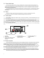
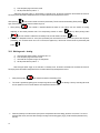
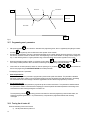
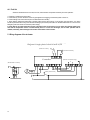
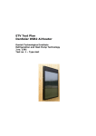
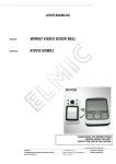
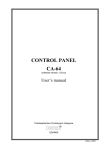
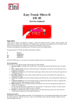
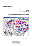
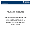
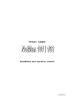
Przedsiębiorstwo Produkcyjno-Wdrożeniowe „ARAJ” sp. z o.o.
55-080 Kąty Wrocławskie, ul. Mireckiego 30
POLAND
USER’S
MANUAL
AIR HEATER
TermEfekt
Model PGA 14
Kąty Wrocławskie, 2004
Product identification
Product name : TermEfekt Air Heater
Model:
PGA 14
The TermEfekt Air Heater essentially consists of the three basic units:
- heater frame
- burner
- control system
Manufacturer’s details:
• Name : Przedsiębiorstwo Produkcyjno - Wdrożeniowe „ARAJ” sp. z o. o
• Address : Poland, 55-080 Kąty Wrocławskie, ul. Mireckiego 30
• Phone number : (+48 71) 39-13-139
Rating plate location: on the heater wall
Introduction
This user’s manual is attached to the product. Read this user’s manual carefully and observe the directions herein in order
to ensure a long-lasting and reliable operation of the unit. In the case of any doubts with regard to the text of this user’s manual,
and/or the use of the product, please call your supplier or manufacturer’s service support.
Safety alert symbol
Indicates important information concerning a hazardous situation, which is given
in the user’s manual.
If you see this symbol, watch out and carefully read the relevant information, and
also alert other users!
The compliance with the manufacturer’s requirements in respect of unit operation and repairs, and their strict observance constitute the
condition of use according to its purpose.
The unit should only be used, operated, and repaired by persons that are familiar with its detailed characteristics and safety
procedures.
Always observe the accident prevention regulations, as well as all basic regulations regarding the health and work safety.
The manufacturer may decline its responsibility for damage or injury in the case of any modifications to the product that were made
without manufacturer’s consent.
Purpose of the unit
The air heaters manufactured by Przedsiębiorstwo Produkcyjno-Wdrożeniowe "ARAJ" are intended for heating and clean
air ventilating of industrial and public facilities.
Typical air heater applications include: workshops, industrial and commercial premises, warehouses, churches, concert
halls, health resort facilities, greenhouses and foil tunnels, etc.
2
TABLE OF CONTENTS
1. Safety precautions and warnings
4
2. Technical characteristics of the air heater
2.1. Construction of the air heater
2.1.1. Heater frame
2.1.2. Burner
2.1.3. Control system
2.2. Principle of operation
2.3. Technical data
5
5
6
6
6
6
7
3. Operating instructions
3.1. Working conditions
3.2. Fuel system
3.2.1. Light fuel oil
3.2.2. Natural gas or liquefied petroleum gas
3.3. Flue system
3.4. Installation requirements
3.5. Use description
3.5.1. Measurement of temperature
3.5.2. States of alarm
3.5.3. Switching the power supply on
3.5.4. Power supply outage
3.5.5. Working mode – start-up
3.5.6. Working mode – heating
3.5.7. Programming user’s parameters
3.5.8. Turning the air heater off
7
7
7
7
8
8
9
9
9
9
9
9
10
10
12
13
4. Inspections, maintenance, and regulation of the air heater
4.1. Daily operational inspection
4.2. Post-seasonal operational inspection
4.3. Pre-seasonal inspection of the air heater
4.4. Fault list
13
13
13
14
14
5. Wiring diagrams of the air heater
14
3
1. Safety precautions and warnings
To ensure the safety of people operating the air heater, as well as
those staying nearby, it is necessary to observe the following
precautions:
1.
2.
3.
4.
5.
6.
7.
8.
9.
10.
11.
12.
13.
14.
15.
16.
17.
18.
4
Get familiar with the user’s manual, health and work safety conditions, and fire precautions.
The unit must not be operated by persons that have not been trained by PPW “ARAJ” authorized service in the scope of its use
and operation, and by those not trained in the scope of the health and work safety, and fire regulations.
Keep children well away from the unit, when in operation.
Ensure free air inflow to the heater fan and burner.
Ensure the proper cross sectional area and unblocked condition of the flue outlet pipe and ventilation system.
Do not use an open fire in the close vicinity of the unit.
Do not start the unit with the fan covering panels removed.
Immediately turn off the burner in the case of any signs of abnormal operation of the unit, e.g. when there is a smoke at the flue
pipe outlet.
Do not turn the power off during operation of the unit – wait until the heat exchanger is completely cool.
Keep the area around the unit clean and tidy.
Aerate the unit before starting, after each break in operation.
Protect the fuel pipes against damage and fuel leaks. Their layout should not hinder immediate leakage detection.
Repairs and maintenance of the electrical system of the air heater may only be performed by qualified electricians in
accordance with the regulations in force.
The facility must be provided with handheld fire extinguishing equipment: one 6 kg dry powder extinguisher, and additionally
one 6 kg dry powder extinguisher for oil tank protection. Dry powder or carbon-dioxide extinguishers may be used as the fire
extinguishing equipment.
Location of the fire extinguishing equipment:
- properly mark the area of fire extinguishing equipment
- allow easy access, one metre wide as a minimum, to the fire extinguishing equipment
- the equipment should be at least 1 metre away from the heat source
- the access path to the equipment should not be longer than 30m.
The fire extinguishing equipment should be subjected to inspections and maintenance according to the manufacturer’s
recommendations, however, at least once a year.
The air heater supplied with single-phase mains voltage should be connected to an earthed socket protected with 10A
fuse.
Any installation and maintenance work must be carried out after disconnecting the unit from the electrical mains.
It is forbidden to:
1.
2.
3.
4.
5.
6.
remove the drive shields during operation of the air heater.
remove the safety thermostat sensor during operation of the air heater.
stay opposite the combustion chamber sight-glass during the start-up of the air heater.
place the fuel tanks in the air heater vicinity.
spill fuel in the close vicinity of the air heater.
place fuel tanks in the close vicinity of walkways and crossings (to avoid possible damage).
2. Technical characteristics of the air heater
2.1. Construction of the air heater
Fig. 1. Construction of PGA 14 air heater.
1.
2.
3.
4.
5.
Burner
Fan
Room thermostat
Combustion chamber
Heat exchanger
6.
7.
8.
9.
Safety thermostat sensor
Air temperature sensor
Safety thermostat button
Power switch
10.
11.
12.
13.
14.
Fuel pipe
Fuel filter
Air intake grille
Power lead
Heating unit housing
15. Combustion chamber sightglass
16. Flue gas outlet
17. Heating unit controller
18. Free blowing distribution heads
5
2.1.1. Frame of the air heater
The frame of the air heater consists of housing, a ventilation section, combustion chamber and heat exchanger. The
housing is a self-supporting structure made of galvanized sheet steel. It is enclosed in shield panels insulated from the interior
side with fireproof compressed fibrous material. The ventilation section consists of a centrifugal fan mounted on the resilient
support, and driven by the electric motor.
Fuel combustion takes place in the combustion chamber which is in the shape of cylinder. The heat exchanger is made up
of specially designed tubes ensuring the maximum heat exchange area while maintaining the minimum flow resistance to air
and flue gases.
2.1.2. Burner
The PGA 14 air heater utilizes blast burners fed with light fuel oil, natural gas or liquid petroleum gas (LPG).
The installed burner construction is described in the attached operating instructions for the burner.
2.1.3. Control system
The air heater is supplied with a suitable, modern, and easy-to-use controller. It has been developed with the use of
microprocessor technology.
The controller is equipped with a sensor for measuring the temperature of air blown away from the air heater, and one
digital input for connecting the thermostat which controls the air heater operation in respect of ambient temperature (Fig.1).
The air heater controller stabilizes the temperature in a room, and controls the fuel combustion process in the air heater.
Control parameters may be adjusted to current working conditions. The controller is also provided with a protection system against
power failure and other types of disturbance.
The outlet air temperature sensor (Fig.1, item 7) should be mounted in the outlet air duct or in one of the free blowing
heads.
1
7
2
3
5
6
4
Fig. 2. Heating unit control panel.
1.
2.
3.
Fan switch
Burner switch
Operating mode change-over switch
(interior circulation and exterior
circulation)
4.
5.
Programming button
Parameter decrease button (in
programming mode)
6.
7.
Parameter increase button (in
programming mode)
Display
2.2. Principle of operation
The fuel fed from the nozzle combines with air to make combustible air-fuel mixture. The proper air pressure is maintained
by the burner fan, and the air-fuel mixture is ignited by electric arc. The flame resulting from burning the fuel-air mixture in the
combustion chamber makes it hot. The hot flue gases flowing through the chamber, and then through the heat exchanger causes
the intensive heating of exchanger tubes. The flue gases are blown away through the flue draught to the atmosphere.
The centrifugal fan located in the upper part of the air heater draws in the external air through the inlet grille, forcing it up to
the exchanger area. The air flows round the combustion chamber and exchanger tubes heated by the flue gases. In the course of
this flow, there is intensive heat exchange between the flue gases and the clean air.
The warm air is blown into the heated room either directly or through the ducts. Due to the low thermal inertia of this
system, almost immediately after turning the unit on the air reaches the desired temperature, which is automatically maintained with
the use of thermostats. An immediate reaction of the system to changing weather conditions ensures the optimal fuel consumption.
With its burner turned off, the air heater may provide a ventilating function.
6
2.3. Technical data
unit of
measure
Air heater model
Heat output
Heat efficiency
Electrical supply
Power input
Rated air flow at to=20 °C
Compression
Air temperature increase
Dimensions length x width x height
Weight without burner
Flue outlet diameter
Maximum light fuel oil consumption
Maximum natural gas consumption (GZ 50)
Maximum liquefied petroleum gas consumption (propane)
Noise level at distance of 1.5 m from air heater
to – ambient temperature
kW
%
V/Hz
kW
m3/h
Pa
°C
mm
kg
mm
l/h
m3/h
kg/h
dB
PGA 14
16
91
220/50
0,44
1 100
100
40
630 x 432 x 1075
80
103
1,7
1,9
1,3
69
Table 1. Technical data of PGA 14 air heater
3. Operating instructions
3.1. Working conditions
-
intake air temperature
ambient temperature
air humidity max
dustiness max (without using air filter)
electrical supply
working position
-25°C ÷ 40°C
-5°C ÷ 40°C
95%
1mg / m3
230/50 Hz
upright
3.2. Fuel system
The fuel system of the air heater should be installed by qualified
staff in accordance with the regulations and standards in force, and
approved design.
Depending on the burner applied, the air heater may be supplied with light fuel oil, natural gas, or liquefied petroleum gas.
3.2.1. Light fuel oil
In order to ensure the proper operation of the unit, it is necessary to use the light fuel oil of the following properties:
- viscosity
1.16 – 1.48°E at 20°C
- calorific value
42 MJ/kg
7
It is forbidden to use petrol, solvents, alcohols or other
inflammable fuels, as well as bad quality fuels.
When the air heater is operated below +8°C, it is recommended to
incorporate an adequate fuel pre-heater into the fuel system, in
order to maintain the proper fuel temperature.
Use of improper oil may lead to:
- clogging of the fuel filter or fuel nozzle,
- build-up of carbon deposit on ignition system electrodes,
- faulty operation of the burner or its damage.
Consideration should be given to the venting of fuel pipes.
Immediately before the burner, it is necessary to apply a fuel filter and a cut-off valve.
Storage area for fuel oil should be subjected to the construction regulations in force.
The fuel pipes should be rigid, made of metal, permanently fixed, and perfectly tight.
3.2.2. Natural gas or liquefied petroleum gas
When using gas fuel, it is necessary to take special safety measures! The gas supply system must be tight and must have
an appropriate conformity certificate or UDT authorization. Immediately before the burner, a cut-off valve must be applied. For boiler
houses above 60 kW, their gas installation should incorporate a solenoid valve (outside the heater room) that reacts to the signal
from a sensor on detecting the presence of gas in the heater room.
Air heaters operated by liquefied petroleum gas should be connected to the tank in such a manner as to ensure the safety
of people and the environment.
3.3. Flue system
The flue should meet the following conditions:
- must be tight and made of appropriate materials to ensure that it is resistant to normal mechanical stresses,
as well as to corrosive effects of combustion products and their condensation.
- flue outlet situated close to the building forming an obstacle should be 0.3m above the obstacle edge as a minimum (for
stacks situated in a distance up to 1.5m from this obstacle)
- maximum deflection of the stack should not exceed 30°
- cross sectional area of the flue should be uniform and smooth in the whole length
- the flue should be insulated in order to prevent the condensate from freezing
Improperly installed flue system may cause damage to the burner
and fire hazard!
3.4. Installation requirements
8
The location, in which the PGA 14 air heater is installed should permit the provision of adequate air supply to ensure the
proper fan operation (Table 1. – rated air flow).
When the unit uses recirculated air (only the air from the heated room), it is only required that the air intake grilles are not obstructed.
When using the fresh air, adequate supply of this air must be ensured, and there should be an efficient ventilation system.
When using the air mixing system, the total air supplied to the air heater must ensure the proper operation of the unit fan, and there
should be an efficient ventilation system.
Site the air heater on hardened (e.g. concrete) foundation in accordance with the general and local guidelines for blast air
heating stoves, and fire regulations.
The flue system should be installed in accordance with the specific regulations in respect of the type of roof, type of stack
and its running path. Prior to connecting to the unit, it is recommended to take advice from a proper chimney master.
3.5. Use description
3.5.1. Measurement of temperature
The controller indicates the measurement of temperature in the range from -10°C to 55°C. In the case of temperature
sensor failure, as well as in the case that the measured temperature is outside the above range, the controller reports the sensor
failure, which results in switching off all the active devices (i.e. the fan, and burners), and switching to the alarm mode.
3.5.2. States of alarm
The controller distinguishes 6 states of alarm. In each of them, an alarm code is displayed. Exit from the state of alarm is only
possible by turning the power supply off. After release of alarm, the fan will be turned on for 5 minutes, and then it will be turned off.
The AL6 will be released if, when heating the air from the room interior, with the room thermostat closed, the temperature reaches
the value Tfan=D1, and then drops to the value Tfan-5°C. With the closed cycle, it is recommended to set the fan activating
temperature in the lower range of D1 settings, i.e. 15-30°C, and D0 (setting for the air heater outlet temperature) should be 10° C
higher, i.e. in the range 40-55°C.
Types of alarm:
•
•
•
•
•
•
AL1
AL2
AL3
AL4
AL5
AL6
Æ
Æ
Æ
Æ
Æ
Æ
opening the temperature sensor (e.g. cable cut)
readout of temperature outside the range (below 0oC)
readout of temperature outside the range (above the factory-set temperature)
temperature sensor shorted
reaching the critical (factory-preset) temperature
lack of fuel or damage to the burners – but only in the closed cycle heating option.
3.5.3. Switching the power supply on
After connecting the unit to the mains, the display shows 3 dots, then the version number of programme used by the
controller, then again 3 dots, and finally the outlet air temperature is displayed, and the controller reads the latest settings of working
parameters.
3.5.4. Power supply outage
The controller is set to take certain actions when power outage occurs, and these actions will depend on its state before
the power outage. The controller will wait for 1 minute to allow the stabilization of power supply system, and then return to work with
the recently programmed parameter values.
During the waiting period, the display shows the time remaining to its end, and the designation of state before the power
supply outage: blinking digit “2” means heating of air from the room interior, and digit “3.” means heating of air from the room
exterior. Along with a digit, the corresponding LED (interior or exterior air heating mode) blinks as well.
3.5.5. Working mode – start-up
a)
check the power switch position, it should be set to “O”
9
b)
c)
insert the power plug to the mains socket
set the power switch to position “1”
After turning the power supply on, the controller is in standby mode. All devices connected to the controller are turned off.
The display shows the outlet air temperature of the air heater measured by the temperature sensor.
, the fan in the air heater is turned on permanently. The fan indicator starts blinking. When pressing
When pressing
again, the fan will be turned off, and the indicator will go out.
• When pressing
, the controller is switched between the states of room interior and room exterior air heating,
depending on the recently selected mode. The corresponding indicator on button
lights up. When pressing button
again, the controller is switched to the standby mode, and the indicator on button
goes out.
• An increase in temperature to the D1 value (user’s parameters) will cause the fan to turn on, and a drop to the value D1(user’s
parameters) -5°C will cause the fan to turn off. Of course, this applies only if the fan has not been turned on permanently with
button
.
3.5.6. Working mode – heating
a)
b)
c)
d)
check the power switch position, it should be set to “O”
insert the power plug to the mains socket
check that the fuel system is tight, and fuel present
set the power switch to position “1”
After turning the power supply on, the controller is in standby mode. All devices connected to the controller are turned off.
The display shows the outlet air temperature of the air heater measured by the temperature sensor.
, the controller will switch to the heating mode.
1.
When pressing button
2.
This mode is signalled by lighting up the corresponding indicator button
. The heating is done by controlling the burner
and fan operation in such a manner that the room temperature remains stable.
3.
When the (external) room thermostat is open (shows a temperature above the setting), the burner is turned off. As soon as
the thermostat closes, the burner starts working according to the following graph (Fig.3) (Toutlet is the D0 parameter set by
the user)
10
Temp
Burner 1
Burner 1 ON
Toutlet=D0
Toutlet-D5=0°C
Time
Fig. 3
4. When heating the air from the room interior, the closing of thermostat immediately activates the fan.
5. When heating the air from the room exterior, the fan will be activated only if the outlet air temperature has reached the Tfan
temperature (D1 parameter) set by the user, as shown in the graph below (Fig.4). This applies to the situation when the
thermostat is closed.
Temp
Fan ON
Fan ON
Tfan
Tfan-5°C
Fan OFF
Time
Fig. 4
6. When the thermostat is open, the air heater cools down. The fan is turned off, when the temperature drops to the value Tfan 5°C, and it will be turned on again, when the temperature rises to Tfan (Fig. 5).
11
Fan ON
Temp
Fan OFF
Tfan
Tfan-5°C
Fan OFF
Time
Fig. 5
3.5.7. Programming user’s parameters
•
•
After pressing button
, the controller is switched to the programming mode, which is signalled by the lighting of indicator
. Programming does not affect the current operation of the controller.
on button
With the use of arrow buttons, the value of the desired parameter can be modified. Keeping the arrow pressed for a longer time
will cause an automatic increase or decrease of the value depending on the chosen direction of change. Values change in a
loop, i.e. after reaching the end of a given parameter range, it will switch to the value from the opposite end of its range.
•
again, as each pressing of button
When the parameter has been modified, it is necessary to press button
the currently modified parameter value to be saved and switching to the programming of the next parameter.
•
If this button has not been pressed for about 10s from the pressing of any of buttons
exit from the programming mode WITHOUT SAVING the modified parameter.
,
,
causes
, the controller will
The displaying sequence of parameters:
1.
Outlet temperature D0
The permissible range for this parameter is programmed by the air heater system manufacturer. This parameter is identified
with the D0 symbol that is visible for a short time before displaying its value that specifies the outlet temperature in the heating
unit at which the burner or the first stage of the burner (applicable for burners with two-stage operation) is turned off .
2.
Fan off temperature D1
The permissible range for this parameter is programmed by the air heater manufacturer. This parameter is identified with the
D1 symbol that is visible for a short time before displaying its value that specifies the outlet temperature in the heating unit at
which the fan is turned off during heating the room exterior air.
will bring you back to the state from which the programming mode has been called, and
The next pressing of button
switch the programming indicator off. It is possible that only one parameter is programmed with the other remaining
unchanged.
3.5.8. Turning the air heater off
When the ventilating of the room is finished:
a) set the power switch to position “O”
12
When the heating of the room is finished:
a)
b)
to turn off the burner of the air heater (the fan will work until the heat exchanger is cooled
press button
down)
set the power switch to position “O”
It is not allowed to turn the air heater off with the power switch, as
this may cause damage to the heat exchanger.
4. Inspections, maintenance and regulation of the air heater
4.1. Daily operational inspection
During the daily inspection, check:
1. that the air heater vicinity is clean and tidy.
2. for fuel leaks from the fuel system.
3. the air heater connection to power supply.
4. that the fan operates correctly.
5. the level of air filter contamination – if necessary, renew the air filter (if installed).
The controller of the heating unit does not require any specific maintenance work. Its keyboard has been made from the
special type of foil resistant to high temperatures, and most chemical agents. It is not allowed to clean it with sharp objects; wiping it
with a wet cloth from time to time will be sufficient.
4.2. Post-seasonal operational inspection
When the season is over, it is necessary to:
Check and possibly clean the fuel filter, and eliminate the air from the fuel system. The air in the fuel system is the most frequent
reason of problems with starting the burner.
1. Check that the burner works properly. In the case of smoking or problems with starting the burner, carry out the regulation of
the burner.
2. Clean the burner according to the recommendations given in the operating instructions for the burner.
During the warranty period, any regulations of the burner should
be carried out by the PPW ARAJ authorized service.
Using bad quality fuel is a frequent reason of improper operation
of the burner.
Note: Both during and after the warranty period, burner regulation and nozzle replacement services are chargeable.
4.3. Pre-seasonal inspection of the air heater
The proper preparation of the air heater to a new season will allow avoiding many faults and contribute to the increase of
service life of the unit. For these purposes, check that all the items of the daily and post-seasonal inspections have been
accomplished.
13
4.4. Fault list
When the disturbances have occurred, first of all, check the basic components necessary for burner operation:
1. Presence of voltage in the power mains;
2. Correct delivery of fuel to the burner: check for pipe tightness and clogging, and that the system is free of air;
3. Correct settings of all control devices (the room thermostat and controller);
4. Check that the safety thermostat button is pressed (after removing the covering); if not pressed, press the button – this action
should be performed after cooling down the heat exchanger (the most frequent reason for the thermostat button to come out is the
emergency shut-down of the unit due to the power outage);
5. Check that the air outlet temperature sensor is mounted in the air outlet duct or in one of the free blowing heads (in the
case that the temperature sensor is located directly above or on the heat exchanger, the air heater operation will be
unstable, which may lead to damage to the sensor and to failure of the air heater.
5. Wiring diagrams of the air heater
6.
Diagram of single-phase control PGA14: 30; 50
(Outlet air sensor)
(Room thermostat)
Controller
(Backlit button switch)
(Safety thermostat)
14
(Burner connection strip)