1
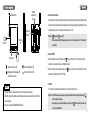
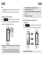
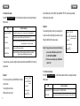
GSM MODULE USER MANUAL
- 401G
Product introduction
Content
Product introduction
3
Feature and parts
4
Operation
5
LED status indication
17
Trouble shooting guide
18
Specification
19
Thank you for purchasing our products of building intercom system series,please read the instruction
carefully and follow the directions before installing the products.
Any problem regarding to the products, please inquire your supplier.
General features
Enable the outdoor unit remote talk with telephone/mobile phone.
Enable the telephone/mobile phone remote unlock the door.
SMS remote setup the module (incl. system menu, function menu, VIP unlock menu)
VIP unlock the door (without charge)
Product’s function
Be connected with our 4-wired video door phone (which system is able to connect with at least 4pcs indoor units with
intercommunication function), to reach the function of remote talk or unlock between phone and outdoor unit. Also the
SMS remote setup module function is available.
CAUTION: To avoid the risk of electric shock, please don’t remove cover or back. Please ask
professional person if maintenance needed.
Remind users that important operation and maintenance guide are included in the attached
user’s manual.
* The manufacturer reserves the right to change or modify designs, features, functions and
specifications without any prior notice for the improvement and promotion of product’s quality,
please refer to the real products.
13062801
2
3
Operation
Features and parts
Software
programming
terminal
GSM antenna
1. Power status indication
After connecting to the power, the power LED(red) will be lighted all the time.Away LED(red) starts to
flash which means the module is under registration. while the away LED(red) stops flashing, and the
Connection
terminal
signal LED(green) turns on, that means the module starts to work.
.
Remark:1.
SIM card
slot
SIM card
-Power LED,
- away LED
2.If there has the other LED flasheing, please refer to the “ Features and parts” or “ LED indication”
introduction
2. Power ON/OFF
Button area
a.When the module is under OFF status, press
Away button/ Away LED
Reset button/ Signal LED
Message button/ Message LED
(Unlock record check)
Power button/ Power LED
Remark
1. During the operation, please press the center of buttons.(As above picture)
2. The SIM card should be had the caller ID display function, please consult with your local GSM
network operator.
3. The unit is only supported GSM900/1800 network.
button, it will sound "DI" and then enter into the
standby mode, meanwhile, the power LED(red) lights on.
b.When the module is under standby status, press
button, it will sound "DI" and all LED will turn off,
that means the module enter into OFF mode.
3. Restart
If the module is worked abnormally, please press”” button to restart the unit.
.
Remark: 1. If the SIM card loose contact, please pull out the SIM card and insert it again, and then press
button to restart the module.
2. Every time when you insert the SIM card, you have to press
button to restart the module, or it
may not read the SIM card.
4
5
Operation
Operation
4. Reset
administration password. Please refer to the function menu setup of Part 6.3.
Press and hold
button till the signal LED(green) flashes, which means the module is entering into
the reset mode. When the module sounds "DI", means you have reset the module successfully.
4.The administration password is defaulted to 8888.
5.If you changed the binding password, the bound mobile phone number can not setup the menu
Anymore.
5. Binding the mobile phone number to the GSM module
Send SMS *Admin password*00# to 401G module’s phone number, the user will get the replied
SMS which include the detail of the menu, which include the binding password, which means the
mobile phone number has been successfully bound to the module.
5.Save the SMS for more convenient operation.
6. SMS to setup the module (should be bound the mobile phone No. First)
6.1 To get the setup menu
Send SMS *Admin password*00# to 401G module’s phone number, the user will get the replied
SMS which include the detail of three menu: System Menu, Function Menu and VIP Unlock Menu.
Binding password
(autogeneration)
System Menu
Function Menu
VIP Unlock Menu
Remark: 1.You have to bind the mobile phone number for the initial using, or you can not setup the functions
via SMS.
2.If you want to bind another mobile phone number, just do the same as the above operation.
3.If you want to cancel the bound mobile phone number, you could reset the module or change the
6
Remark: Save the SMS for more convenient operation.
7
Operation
Operation
6.2 System menu setup
Send modified menu to 401G by SMS. If get replied SMS “SET OK”, means setup successfully.
Send SMS *Admin password*11# to 401G module’s phone number, the user will get the replied
Modify system menu as below
SMS as below:
Function commentary
SMS
1-Away Set: 0; (1-ON,0-OFF)
【Away setup】0-Turn off away mode 1-Turn on away mode (Factory setting default to 0.)
2-Tran Tel1 Set: ;
【1st transfer phone number setup】Max. support 20 digits, not allow "*" or "#"
3-Tran Tel2 Set: ;
【2nd transfer phone number setup】Same operation as the above. More detail information
referring to Operation 13 – Call remind / transfer.
4-Unlock Key:0; (0-9)
【Unlock key setup】Factory setting default to 0.
5-Binding PWD:****;
【Binding password】The password will be automatically generated after the user bind the
mobile phone number. (Modify the password is not allowed.)
Example 2:
If unsuccessfully setup the unlock key, and away mode is
1-Away Set: 1; (1-ON,0-OFF)
turned on but without transferring phone number, the user
2-Tran Tel1 Set:NO TELEPHONE NUMBER ;
Will get the SMS by 401G module as below:
3-Tran Tel2 Set: ;
4-Unlock Key:FAIL; (0-9)
Remark: 1. If away mode is turned on, but without transferring
5-Binding PWD:****;
phone number, the SMS will be replied “Tran Tel1
Set: NO TELEPHONE NUMBER”.
2. If the item is unsuccessfully setup, the SMS will be
To setup the menu, you need to modify the menu details, and then send the SMS to 401G module’s
replied ” FAIL”.
phone number.
6.3 Function menu setup
Example 1:
To turn on away mode To setup 123456789 as 1st transfer
phone number
1-Away Set: 1; (1-ON,0-OFF)
2-Tran Tel1 Set:123456789 ;
3-Tran Tel2 Set: ;
To setup digit 8 as unlock key
Modify system menu as right
8
Send SMS *Admin password*22#
to 401G module’s phone number, the user will get the replied
SMS as below:
SMS
Function commentary
4-Unlock Key:8; (0-9)
1-Time Set:2011/11/11,11:11:11; 【Date/Time Setup】Format: YYYY/MM/DD,HH:MM:SS
5-Binding PWD:****;
2-PWD Set:8888
【Admin password setup】Admin password should be 4 digits (Factory setting default to 8888)
9
Operation
3-Unlock Time:3; (1S-9S)
4-Binding PWD:****;
Operation
【Unlock time setup】Could be setup between 1 to 9 seconds. (Factory setting default to 3
seconds.)
【Binding password】The password will be automatically generated after the user bind the
mobile phone number. (Modify the password is not allowed.)
Remark: Please change the admin password when you use it for the first time.
For example:
1-VIP UNLOCK EN:1; (1-ON,0-OFF)
To turn on VIP unlock function
2-VIP UNLOCK TEL1:123456789;
To setup 1st VIP phone Number as 123456789
3-VIP UNLOCK TEL2: ;
Modify VIP unlock menu as right:
4-VIP UNLOCK TEL3: ;
.
5-Binding PWD:****;
Send modified menu to 401G by SMS. If setup successfully, when phone numberc123456789 call
6.4 System menu setup
401G module’s phone number, it will unlock the door directly.
Send SMS *Admin password*33#
to 401G module’s phone number, the user will get the replied
.
6.5 Check unlock records
SMS as below:
a. Any phone number
Function commentary
SMS
Send SMS
1-VIP UNLOCK EN:0; (1-ON,0-OFF) 【Turn on/off VIP Unlock function】0-Turn off 1-Turn on (Factory setting default to 0.)
*Admin password*44
to 401G module’s phone number, the user will get the replied
SMS which indicated the latest 5 unlock records.
st
2-VIP UNLOCK TEL1
【Setup 1 VIP unlock phone number】
3-VIP UNLOCK TEL2
【Setup 2nd VIP unlock phone number】
4-VIP UNLOCK TEL3
【Setup 3 VIP unlock phone number】
Press and hold
5-Binding PWD:****;
【Binding password】The password will be automatically generated after the user bind the
mobile phone number. (Modify the password is not allowed.)
latest 5 unlock records.
.
b. Transfer phone number
rd
button till it sounds "DI", the user will get the replied SMS which indicated the
.
Remark: 1. Only the 1st transfer phone number can receive latest 5 group of unlock records by pressing
VIP unlock function introduction: When turn on VIP unlock function, the pre-setup VIP unlock phone
button. The 2nd transfer phone number need to send SMS *Admin password*44 to get records.
number call 401G module’s phone number, the door will be unlocked automatically after “DU”. (The
2. The function of pressing to get unlock records is not available if the unit is only setup the 2nd
module is no needed to answer the call, and the call is without any charge).
transfer phone number.
3. Refer to operation 6.2 to see how to setup transfer phone number.
10
11
Operation
Operation
【Format of unlock record message: phone number; date; time; door station number】
d. Setup unlock key
*Admin password*4*N#
For example
Send SMS
123456789;2013/03/13,15:15:15;DOOR1
Remark: If you get replied SMS “SET OK”, means setup successfully.
to 401G.(N stands for digit from 0 to 9.)
If you get replied SMS “SET FAIL”, means setup unsuccessfully.
It means phone 123456789 unlock Door1 on 15:15, 13th March 2013.
7.Help
6.6 SMS to setup individual function
Send SMS help to 401G module’s phone number, the user will get the replied SMS as below:
a. Setup away mode
Turn on away mode: send SMS *Admin password*1*1# to 401G.
Turn off away mode: send SMS *Admin password*1*0# to 401G.
SMS
*PASSWORD*00#:Get All Menu
Function commentary
【Get All Menu】
If away mode is turned on, but without transferring phone number, the SMS will be replied "Tran Tel1
*PASSWORD*11#:Get System Menu
【Get System Menu】
Set: NO TELEPHONE NUMBER".
*PASSWORD*22#:Get Function Menu
【Get Function Menu】
.
b. Setup 1st transfer phone number
Send SMS
*Admin password*2*phone number#
to 401G.
.
* or "#"
#
Remark: Max. support 20 digits, not allow "*"
*Admin password*3*phone number#
【Get VIP Unlock Menu】
【Set Away ON】
*PASSWORD*1*0#:Set Away OFF
【Set Away OFF】
*PASSWORD*2*TELEPHONE NUMBER#:Set Transfer Telephone Number 1 【Set Transfer Telephone Number 1】
*PASSWORD*3*TELEPHONE NUMBER#:Set Transfer Telephone Number 2 【Set Transfer Telephone Number 2】
c. Setup 2nd transfer phone number
Send SMS
*PASSWORD*33#:Get VIP Unlock Menu
*PASSWORD*1*1#:Set Away ON
*PASSWORD*4* UNLOCK KEY#:Set Unlock Key, From 0 To 9
to 401G.
【Set Unlock Key, From 0 To 9】
.
* or "#"
#
Remark: Max. support 20 digits, not allow "*"
12
13
Operation
Operation
8.Away setup
Press
11.Away extension terminal
button till the module sounds DI, meanwhile away LED (green ) turns on, means AWAY
When the module is installed in a high position which is not convenient for operation, you can connect
mode set ON.
with an external switch through away extension terminal, to setup away mode.
Press
With the external switch, you will hear the module sounds a short DI when you press the switch,
button till the module sounds DI DI, meanwhile away LED (green) turns off, means AWAY
mode set OFF.
which means the away mode ON. Press the switch again you will hear the module sounds DI DI,
.
which means the way mode OFF.
Remark: 1.if you do not setup the transfer phone number, when you turn on away mode, the module will
.
remind you to setup the transfer phone number with a long DI.
Remark: 1. Press and hold the switch, till the module sounds a short DI, which means the module is
2.The function is invalid when the indoor monitor is turned on away mode which can automatically
successfully restarted.
Record video.
2. If you don’t setup the transfer phone number, you will hear the module sounds a long DI when you
.
press the switch for the first time, which remind you to setup the transfer phone number.
9.Unlock
Under talking mode, double -click unlock key on the mobile phone
to unlock the door.
12.Remind when send the message
1
2
3
4
5
6
Remark: the unlock key is default to 0. Refer to Operation 6.2 – System
7
8
9
manual setup.
*
0
#
.
.
Message LED (red ) on, means the module is sending the message.
After message LED (red) turns green means message send failure. When message LED (green)
turns off without turn on the green LED, which means successfully send the message.
.
10.Volume setup
Remark :
-Message LED
Under talking mode, double click # on the mobile phone to increase talk volume.
Under talking mode, double click * on the mobile phone to decrease talk volume.
.
Remark: Successfully setup with DI, failure with DI DI.
14
15
Operation
13.Outdoor unit call remind / call transfer
LED status indication
1.
Power LED (green) on
Means under talking mode
Under away mode, when outdoor unit calls in, the power LED (green) flashes and transfer the call to
2.
Power LED (green) flash
Means outdoor unit calls in
the transfer phone number.
3.
Message LED (red) on
Means message is sending
A.If you have setup two transfer phone number, when outdoor unit calls in, the call will be transferred
4.
Message LED (green) on
Means failure to send the message
to the 1st phone number. If the visitor call again within 10 seconds, the call will be transferred to the
5.
Message LED (green) flash
Means under reset mode
2nd phone number.
6.
Signal LED (green) on
Mean signal is normal
7.
Signal LED (red) on
Means signal is weak
transferred to the 2nd phone number directly.
8.
Signal LED (red) flash
Means no signal
Remark: To reach the call transfer function, you will turn on away mode, and setup the call transfer phone
9.
Away LED (red) flash
Means under registration mode
10.
Away LED (red) on
Means no SIM card or poor contact of SIM card
11.
Away LED (green ) on
Means away function is ON
12
Away LED (green) flasht
Means communication problem between the module and the
B.If you only setup the 2nd transfer phone number, when outdoor unit calls in, the call will be
.
number.
14.Alarm for communication problem
If the module sounds DI DI at intervals, meanwhile away LED (green) flashes, which means there is
Indoor unit
communication problem between the module and the indoor unit. Please check the wiring.
16
17
Specification
Troubles shooting guide
Problem
The module totally cannot work
Outdoor unit cannot call.
The module is no response.
The module cannot transfer the
call and send the message.
Possible reason
-The connection between indoor
unit and the module is cut off.
-The connection between indoor
and outdoor unit is cut off.
-The module is under OFF mode.
-Check the connection between indoor unit
and the module.
-Check the connection between indoor and
outdoor unit.
-Refer to Operation 2 – Power ON/OFF.
-Poor signal.
-Poor contact of the SIM card.
-Check the connection of antenna.
-Check if the SIM card is well plugged in,
then press
button to restart the module.
-Please prepaid the SIM card in time.
-No charge of the SIM card.
The module sounds“DI Di”at
intervals.
Model No.
Item
401G
Power Supply
DC13.5-15V/600mA
Connection
In series
Power consumption
13.5V/20mA±5mA (Standby)
13.5V/50mA±10mA (Working)
Support Frequency
GSM900 / DCS1800
Sub Units
Max. support 3PCS 401G
Operation temperature
-10℃ to +55℃
Optional Indoor unit
Any of our 4-wires indoor units
(which should be had the function of connecting with 3pcs extension unit)
-The connection between the
-Check the connection between the
module and the indoor unit is cut off. module and the indoor unit.
When talk with phone, the voice
-Talk volume is too low.
which outdoor can heard is very low.
18
Solution
-The module hasn't connected with -Check if the power is well plugged in.
power.
-The module is under OFF mode. -Refer to Operation 2 – Power ON/OFF.
-Under talk mode, double -click unlock
key on the mobile phone to unlock the door.
Signal LED (red) on
-Poor signal.
-Check the connection of antenna and
installation position.
Signal LED (red ) flash
-No signal
-Check the connection of antenna.
Away LED (red) on
-No SIM card on the module or
poor contact of SIM card.
-Check if the SIM card is well plugged in,
then press
button to restart the module.
19