1
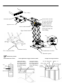
User’s Manual for Motorised Projector Lift
Product Description:
Motorised projector lift(Below simply “lift” for short) adopt double scissor type structure and the theory of double straps
lifting. Featured with elegant appearance design, safety and dependable function, accurate positioning, low noise,
easy-installation, etc. Applicable widely to projection,lighting&audio projects.
1.Product model/Specification/Size Unit:mm
Specifications
SX080
SX100
SX150
SX200
Size of lift Fold up (mm)
350x316x420(L1)
350X316X440(L1)
350X316X480(L1)
350X316X530(L1)
Size of lift Extended (mm)
350x316x1290(L)
350X316X1525(L)
350X316X1995(L)
350X316X2700(L)
440mm
460mm
500mm
550mm
Bottom Plate size(mm)
500x500
500x500
500x500
500x500
Loading Capacity
15Kg(Max)
15Kg(Max)
15Kg(Max)
15Kg(Max)
Rated voltage
220-240V
220-240V
220-240V
220-240V
Max Power consumption
60W
60W
60W
60W
Tilt angle
±22.5°
±22.5°
±22.5°
±22.5°
Roll angle
±15°
±15°
±15°
±15°
Motor
SYNCHRONOUS MOTOR
SYNCHRONOUS MOTOR
SYNCHRONOUS MOTOR
SYNCHRONOUS MOTOR
Minimum dist for ceiling and false
ceiling(mm)
Control Methods
RF/Central
RF/Central
RF/Central
RF/Central
Control/12V
Control/12V
Control/12V
Control/12V
Trigger/panel
Trigger/panel
Trigger/panel
Trigger/panel
Limit Adjustment
By Limit Switch
By Limit Switch
By Limit Switch
By Limit Switch
Color
White
White
White
White
Packing Dimension(mm)
530x530x260
530x530x260
530x530x300
530x530x350
Net Weight(Kgs)
18
18.5
19.5
21
Gross Weight(Kgs)
19.5
20
21
22.5
Installation Enviroment Required:
1.The lift shall work indoor where there is no any corrosive or combustible substance; and should not approach the steam
pipe, hot air pipe, or other central heating equipment.
2.Voltage: 220-240V, Power: 50W
Installation:
1. The distance between ceiling and false ceiling must bigger than the height of fold up size(L1) of the lift..
2. Suggest open dimension on false ceiling for the lift is :450mmX450mm
3. Suggest open a 400mmX400mm maintenance window on the false ceiling, 100mm~200mm away from the back side of
the lift.
4. Drill four holes correctly on the ceiling for the installation plate,considering the direction of the installed projector, then
mount the installation plate of the lift on the ceiling firmly with four ∅8mm explosion screws through the four ∅10mm
screw holes.
5, The explosion screws must installed in concrete or masonry or more strong ceiling. The explosion screws must drill
deeply into the ceiling to keep adequate bearing capability.
Notice:
1. The explosion screws must fixed on the ceiling firmly.
2. While the lift working, people must not stand below the lift, or locate anything at the level where it can reach.
3. Make sure the gravity of the projector in the center of the lift, or the center of the gravity will shift or loss balance;
And the lift can’t work overloaded.
4. Please do not put your hands or anything to the cross-scissor parts while the lift working to avoid injury.;
Trouble shootings:
Please let technicians check below items, if still can’t solve the problems, please contact the resellers.
1. Please check if the connection of the power cord is correct.
2. Please check if the strip is entangled or loose.
3. Please check if the E-Stop button is pressed down.
4. Please check if the limit switch is loose or shift .
Accessories:
A
B
C
D
E
F
A
A
A
A
A
G
G
A
S=3m (X1)
H
A
X2
I
M4X8 (X12)
J
A
A
M8X60 (X4)
Connection Plate X4
K
G
L
G
A
A
Universal Joint X1
M
k
G
Mount
X1
N
O
A
A
A
Cable tie X4
Screw rod
L=240mm
X4
RF Transmitter X1
12V Trigger cable clw
3.5mm Jack plug X1
Central control Cable
clw RJ45 Plug
X1
Power cable X1
Control Panel X1
S=4mm (X1)
Ceiling
Installation plate
Explosion screw(E)
Lower Limit Switch
Upper Limit Switch
Please make sure the
4 screws get through
the holes to correct
position, then lock
the security screw
tightly to prevent the
lower part of the lift
from sliding.
(F)
M4X8 screws(C)
(D)Connection Plate
(G)
M4X8 screws(C)
(I) Connection screw bar
Decorative panel
Manual for product.
1.The manual for remote
(J)
Up
Stop
Down
2.The adjustment of upper and lower limit
Upper limit: Move
leftwards to enlarge
the running distance;
move rightwards to
shorten the running
distance.
Lower limit: Move
leftwards to shorten
the running distance;
move rightwards to
enlarge the running
distance.
3. Input and out put function
DC12V Trigger(K)
Power cable(M)
E-stop
button
RJ45(L)
Control panel(N)
Central Control Encode Table.
No.
Name
Encoding
1
Serial port setup
2400,n,8,1
2
Up
0xFF 0xAA 0xEE 0xEE 0xDD
3
Stop
0xFF 0xAA 0xEE 0xEE 0xCC
4
Down
0xFF 0xAA 0xEE 0xEE 0xEE