1
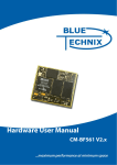
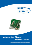
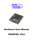
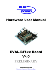
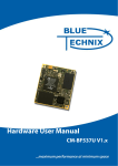
Hardware User Manual EXT-BF5xx-Camera V1.x www.tinyboards.com Maximum Power at Minimum Size Contact Bluetechnix Mechatronische Systeme GmbH Waidhausenstr. 3/19 A-1140 Vienna AUSTRIA/EUROPE [email protected] http://www.bluetechnix.com Document No.: 100-2253-1.0 Version 0.2 2010-07-13 Blackfin EXT-BF5xx Camera Extender Board Hardware User Manual Table of Contents 1 2 Introduction ......................................................................................................................... 1 1.1 Overview ....................................................................................................................... 1 1.2 Possible mount configurations ...................................................................................... 2 1.3 Blackfin Products .......................................................................................................... 3 Specification ........................................................................................................................ 4 2.1 Schematic ...................................................................................................................... 4 2.2 Connectors, PCB Placement and PIN Assignment ....................................................... 4 2.2.1 EX1 – Expansion Connector 1 ............................................................................... 5 2.2.2 EX2 – Expansion Connector 2 ............................................................................... 7 2.2.3 Cam1 – Camera Connector 1 ............................................................................... 10 2.2.4 Cam2 – Camera Connector 2 ............................................................................... 10 2.2.5 P1 – TFT Display Connector ............................................................................... 11 2.2.6 Expansion Connector Types................................................................................. 12 2.2.7 JP1 - Power Supply Jumper ................................................................................. 12 2.2.8 Test Points ............................................................................................................ 12 2.3 Mechanical Outline ..................................................................................................... 13 2.4 Configuration .............................................................................................................. 13 2.4.1 JP1 - Power Supply Jumper ................................................................................. 13 2.4.2 S1 – DIP Switch ................................................................................................... 13 2.4.3 S3 – PWM Timer Select Switch .......................................................................... 14 2.4.4 Timer used to drive TFT-Display signals ............................................................ 14 3 Known Bugs ...................................................................................................................... 15 4 Abbreviations .................................................................................................................... 16 5 Revision History ................................................................................................................ 17 A List of Figures and Tables .............................................................................................. 18 Blackfin EXT-BF5xx Camera Extender Board Hardware User Manual Edition 2005-08 © Bluetechnix Mechatronische Systeme GmbH 2005 All Rights Reserved. The information herein is given to describe certain components and shall not be considered as a guarantee of characteristics. Terms of delivery and rights of technical change reserved. We hereby disclaim any warranties, including but not limited to warranties of noninfringement, regarding circuits, descriptions and charts stated herein. Bluetechnix makes and you receive no warranties or conditions, express, implied, statutory or in any communication with you. Bluetechnix specifically disclaims any implied warranty of merchantability or fitness for a particular purpose. Bluetechnix takes no liability for any damages and errors causing of the usage of this board. The user of this board is responsible by himself for the functionality of his application. He is allowed to use the board only if he has the qualification. More information is found in the General Terms and Conditions (AGB). Information For further information on technology, delivery terms and conditions and prices please contact Bluetechnix (http://www.bluetechnix.com). Warnings Due to technical requirements components may contain dangerous substances. The Core Boards and Development systems contain ESD (electrostatic discharge) sensitive devices. Electrostatic charges readily accumulate on the human body and equipment and can discharge without detection. Permanent damage may occur on devices subjected to high-energy discharges. Proper ESD precautions are recommended to avoid performance degradation or loss of functionality. Unused core boards and development boards should be stored in the protective shipping package. Blackfin EXT-BF5xx Camera Extender Board Hardware User Manual Bluetechnix www.tinyboards.com Maximum Power at Minimum Size 1 Introduction The EXT-BF5xx-Camera Board is an extender plug-on board for the DEV-BF5xx or the EVAL-BF5xx Board. The board supports the Omnivision OV7660 camera modules and/or the TX09D50VM1CCA from Hitachi or compatible devices. 1.1 Overview The EXT-BF5xx-Camera Board includes the following components: Figure 1-1: Overview of the EXT-BF5xx-Camera Board 2 Camera Connectors 1. Supported cameras: OV7660 2. Resolution: 460x480 @ max 30fps or 320x240@ max 60fps TFT Display Connector 3. Supports Hitachi TX09D50VM1CCA (Note 1) or compatible devices. Stacked Connectors 4. For connecting the basis board or other extender boards. The TFT Display TX09D50VM1CCA can be ordered from Bluetechnix. Blackfin EXT-BF5xx Camera Extender Board Hardware User Manual Page 1 Bluetechnix www.tinyboards.com Maximum Power at Minimum Size 1.2 Possible mount configurations The possible mounting configurations are depending on the used Core Module: CM-BF561 1. 2 cameras inserted in Cam1 and Cam2 *1) 2. 1 camera in Cam2 and one display in P1 *2) 3. 1 camera or one display CM-BF533 1. Only 1 camera in Cam1 is possible*3) CM-BF537E/U 1. Only 1 camera on Cam1 *3) 2. Only the display *2) *1) Do not connect the display, if you insert two cameras. The camera Cam1 and the Display share the same PPI interface! *2) Do not connect a camera on Cam1 if the TFT-Display is connected. The camera Cam1 and the Display share the same PPI interface! *3) Leave camera Cam2 and display P1 open! Blackfin EXT-BF5xx Camera Extender Board Hardware User Manual Page 2 Bluetechnix www.tinyboards.com Maximum Power at Minimum Size 1.3 Blackfin Products CM-BF533: Blackfin Processor Module powered by Analog Devices single core ADSPBF533 processor; up to 600MHz, 32MB RAM, 2MB Flash, 24 pin camera connector. CM-BF534U: Blackfin Processor Module powered by Analog Devices single core ADSPBF534 processor; up to 500MHz, 32MB RAM, 4MB Flash, integrated USB 2.0 Device. CM-BF537U: Blackfin Processor Module powered by Analog Devices single core ADSPBF537 processor; up to 600MHz, 32MB RAM, 4MB Flash, integrated USB 2.0 Device. CM-BF537E: Blackfin Processor Module powered by Analog Devices single core ADSPBF537 processor; up to 600MHz, 32MB RAM, 4MB Flash, integrated TP10/100 Ethernet physical transceiver. CM-BF561: Blackfin Processor Module powered by Analog Devices dual core ADSPBF561 processor; up to 2x 600MHz, 32MB RAM, 4MB Flash. All CM-BFxxx Core Modules have two compatible 120pin connectors or a BGA option and a size of 36.5x31.5mm. TCM-BF537: Blackfin Processor Module powered by Analog Devices single core ADSPBF537 processor; up to 600MHz, 32MB RAM, 8MB Flash, 27.4x27.4mm, 120 pin expansion connector or border pads for reflow soldering, industrial temperature range -40°C to +85°C. EVAL-BF5xx: Low cost Blackfin processor Evaluation Board with one socket for any Bluetechnix Blackfin Core Module. Additional periphery is available, such as a SD-Card. DEV-BF5xx: Blackfin Development Board with two sockets for any combination of Core Modules. Additional periphery is available, such as CF-Card, SD-Card, DPRAM, Ethernet, USB host and device, multi-port JTAG, connector for a LCD-TFT Display and 2 connectors for a digital stereo camera system. EXT-Boards: The following Extender Boards are available: EXT-BF5xx-Audio, EXTBF5xx-Video, EXT-BF5xx-Camera, EXT-BF5xx-Experimental. Additional boards based on customer request BLACKSheep: The BLACKSheep VDK is a multithreaded framework for the Analog Devices Blackfin processor family that includes driver support for a variety of hardware extensions. It is based on the real-time VDK kernel included within the VDSP++ development environment. Notes: For product development it is highly recommended to purchase the DEV-BF5xx Blackfin development board and the BLACKSheep VDK low level driver software for the on board peripherals. Blackfin EXT-BF5xx Camera Extender Board Hardware User Manual Page 3 Bluetechnix www.tinyboards.com Maximum Power at Minimum Size 2 Specification 2.1 Schematic Figure 2-1: Detailed Block Diagram 2.2 Connectors, PCB Placement and PIN Assignment The following sections describe the signal and pin assignment depending on witch core module is inserted on the basis board. Figure 2-2: Connector PCB Placement Blackfin EXT-BF5xx Camera Extender Board Hardware User Manual Page 4 Bluetechnix www.tinyboards.com Maximum Power at Minimum Size 2.2.1 EX1 – Expansion Connector 1 The pin assignment of the expansion connector EX1 depends on the core module inserted on the basis board. CM-BF533 inserted on basis board: Pin No Signal 1 3 5 7 9 11 13 15 17 19 21 23 25 27 29 31 33 35 37 39 41 43 45 47 49 51 53 55 57 59 RSCLK0 TSCLK0 RSCLK1 TSCLK1 3V3 PPI0 PF15 / PPI4 PF11 / PPI8 PF7/SPISEL7/PPI12 PF3/SPISEL3/PPI_FS3 TMR0 RX SCK GND n.c. n.c. n.c. n.c. MISO PF0 / nSPISS PPI_CLK PF4/SPISEL4/PPI15 PF8 / PPI11 PF12 / PPI7 PPI3 GND DT1SEC DR1SEC DT0SEC DR0SEC Signal type I/O I/O I/O I/O PWR I/O I/O I/O I/O I/O I/O I I PWR I/O I/O I/O I/O I/O I/O I/O PWR O I O I Pin No Signal 2 4 6 8 10 12 14 16 18 20 22 24 26 28 30 32 34 36 38 40 42 44 46 48 50 52 54 56 58 60 DR0PRI DT0PRI DR1PRI DT1PRI 3V3 PPI2 PF13 / PPI6 PF9 / PPI10 PF5/SPISEL5/PPI14 TMR1 / PPI_FS1 PF1 / SPISEL1 MOSI BMODE0 n.c. n.c. n.c. n.c. BMODE1 TX PF2 / SPISEL2 TMR2 / PPI_FS2 PF6/SPISEL6/PPI13 PF10 / PPI9 PF14 / PPI5 PPI1 GND TFS1 RFS1 TFS0 RFS0 Signal type I O I O PWR I/O I/O I/O I/O I/O I/O I/O I I O I/O I/O I/O I/O I/O I/O PWR I/O I/O I/O I/O Table 2-1: Connector EX1 pin assignment for CM-BF533 CM-BF537E/U inserted on basis board: Pin No Signal 1 3 RSCLK0/TACLK2 TSCLK0/TACLK1 Signal Pin No type I/O 2 I/O 4 Signal DR0PRI/ TACLK4 DT0PRI/SPI_CS2 Blackfin EXT-BF5xx Camera Extender Board Hardware User Manual Signal type I O Page 5 Bluetechnix www.tinyboards.com Maximum Power at Minimum Size 5 7 9 11 13 15 17 19 21 23 25 27 29 31 33 35 37 39 41 43 45 47 49 51 53 55 57 59 CLK_out PF4/TMR5/SPI_CS6 3V3 PG0/PPI1D0 PG4/PPI1D4 PG8/PPI1D8/DR1SEC PG12/PPI1D12/RE1PRI PPI1SY3/PF7/TMR2 PPI1SY1/PF8/TMR0 PF1/DMAR1/TACI1/Rx 0 PF13/SCK GND n.c. n.c. n.c. n.c. PF12/MISO PF14/SPI_SS PPI1Clk/PF15/TMRCLK PG15/PPI1D15/DT1PRI PG11/PPI1D11/RFS1 PG7/PPI1D7 PG3/PPI1D3 GND PF5/TMR4/SPI_CS5 PF10/SPI_SC1 DT0SEC/CANTX/SPICS 7 DR0SEC/TACI0/CANR X O I/O PWR I/O I/O I/O I/O I/O I/O I/O 6 8 10 12 14 16 18 20 22 24 SDA PF5/TMR4/SPI_CS5 3V3 PG2/PPI1D2 PG6/PPI1D6 PG10/PPI1D10/RSCLK1 PG14/PPI1D14/TFS1 PPI1SY1/PF8/TMR0 PF3/Tx1/TMR6/TACI6 PF11/MOSI I/O I/O PWR I/O I/O I/O I/O I/O I/O I/O I/O PWR I/O I/O I/O I/O I/O I/O I/O PWR O I O 26 28 30 32 34 36 38 40 42 44 46 48 50 52 54 56 58 BMODE0 n.c. n.c. n.c. BMODE2 BMODE1 PF0/DMAR0/Tx0 PF2/Rx1/TMR7 PPI1Sy2/PF8/TMR1 PG13/PPI1D13/TSCLK1 PG9/PPI1D9/TD1SEC PG5/PPI1D5 PG1/PPI1D1 GND PF6/TMR3/SPI_CS4 SCL TFS0 I I I O I/O I/O I/O I/O I/O I/O PWR I/O I/O I/O I 60 RFS0/TACLK3 I/O Table 2-2: Connector EX1 pin assignment for CM-BF537E/U CM-BF561 inserted on basis board: Pin No Signal 1 3 5 7 9 11 13 15 17 19 21 RSCLK0 / PF28 TSCLK0 / PF29 PF11(Clk_out optional) PF7/SPISEL7/TMR7 3V3 PPI1D0 PPI1D4 PPI1D8 / PF40 PPI1D12 / PF44 PPI1SYNC3 PF3 / SPICS2 Signal type I/O I/O I/O I/O PWR I/O I/O I/O I/O I/O I/O Pin No Signal 2 4 6 8 10 12 14 16 18 20 22 DR0PRI DT0PRI / PF18 PF9 PF5/SPISEL5/TMR5 3V3 PPI1D2 PPI1D6 PPI1D10 / PF42 PPI1D14 / PF46 PPI1SYNC1 / TMR8 PF1/SPISEL1/TMR1 Blackfin EXT-BF5xx Camera Extender Board Hardware User Manual Signal type I I/O I/O I/O PWR I/O I/O I/O I/O I/O I/O Page 6 Bluetechnix www.tinyboards.com Maximum Power at Minimum Size 23 25 27 29 31 33 35 37 39 41 43 45 47 49 51 53 55 57 59 RX / PF27 SCK ARDY n.c. n.c. n.c. nABE1 MISO PF0/SPISS/TMR0 PPI1CLK PPI1D15 / PF47 PPI1D11 / PF43 PPI1D7 PPI1D3 GND PF4/SPISEL4/TMR4 PF8 DT0SEC / PF17 DR0SEC / PF20 I/O I/O I O I/O I/O I I/O I/O I/O I/O PWR I/O I/O O I 24 26 28 30 32 34 36 38 40 42 44 46 48 50 52 54 56 58 60 MOSI nABE2 n.c. n.c. n.c. nAMS3 nABE0 TX / PF26 PF2/SPISEL2/TMR2 PPI1SYNC2 / TMR9 PPI1D13 / PF45 PPI1D9 / PF41 PPI1D5 PPI1D1 GND PF6/SPISEL6/TMR6 PF10 TFS0 / PF16 RFS0 / PF19 I/O O O O I/O I/O I/O I/O I/O I/O I/O PWR I/O I/O I/O I/O Table 2-3: Connector EX1 pin assignment for CM-BF561 2.2.2 EX2 – Expansion Connector 2 The pin assignment of the expansion connector EX1 depends on the core module inserted on the basis board. CM-BF533 inserted on basis board: Pin No Signal 1 3 5 7 9 11 13 15 17 19 21 23 25 27 29 31 33 A1 A5 A9 A13 A17 ABE1 n.c. 1V8 n/BG GND nAWE D0 D4 D8 D12 D15 D11 Signal type O O O O O O O O PWR O I/O I/O I/O I/O I/O I/O Pin No Signal 2 4 6 8 10 12 14 16 18 20 22 24 26 28 30 32 34 A3 A7 A11 A15 A19 n.c. n.c. ADRY CLK_Out 25MHz nAMS3 NMI D2 D6 D10 D14 D13 D9 Blackfin EXT-BF5xx Camera Extender Board Hardware User Manual Signal type O O O O O I O O I I/O I/O I/O I/O I/O I/O Page 7 Bluetechnix www.tinyboards.com Maximum Power at Minimum Size 35 37 39 41 43 D7 D3 nRESET nARE VDD-RTC I/O I/O I O PWR 36 38 40 42 44 45 47 49 51 53 55 57 59 nBR n.c. n.c. ABE0 A16 A12 A8 A4 I O O O O O 46 48 50 52 54 56 58 60 D5 I/O D1 I/O nAOE O nAMS2 O nBGH (at Slot B via O R205) n.c. n.c. n.c. A18 O A14 O A10 O A6 O A2 O Table 2-4: Connector EX2 pin assignment for CM-BF533 CM-BF537E/U Pin No Signal A1 A5 A9 A13 A17 nABE1 GND PH7/RX- (Note 2) nBG/USBD+ (Note 1) GND nAWE D0 D4 D8 D12 D15 D11 D7 D3 nReset nARE VDD-RTC nBR PH6/TX- (Note 2) PH2/LED_FD (Note 2) Signal type O O O O O O I O PWR O I/O I/O I/O I/O I/O I/O I/O I/O I O PWR I O O 1 3 5 7 9 11 13 15 17 19 21 23 25 27 29 31 33 35 37 39 41 43 45 47 49 51 53 Pin No 2 4 6 8 10 12 14 16 18 20 22 24 26 28 30 32 34 36 38 40 42 44 46 48 50 nABE0 A16 O O 52 54 Signal Signal type A3 O A7 O A11 O A15 O A19 O PH1/LED_ACT (Note 2) O PH5/RX+ (Note 2) I ADRY I CLK_out O nAMS3 O NMI I D2 I/O D6 I/O D10 I/O D14 I/O D13 I/O D9 I/O D5 I/O D1 I/O nAOE O nAMS2 O nBGH/USBD- (Note 1) O PH8/VA25 (Note 2) PWR TX+ (Note 2) O PH0/LED_SPEED (Note O 2) A18 O A14 O Blackfin EXT-BF5xx Camera Extender Board Hardware User Manual Page 8 Bluetechnix www.tinyboards.com Maximum Power at Minimum Size 55 57 59 A12 A8 A4 O O O 56 58 60 A10 A6 A2 O O O Table 2-5: Connector EX2 pin assignment for CM-BF537E/U Note 1: The USB signals are only available with CM-BF537U inserted otherwise alternate signal function is available. Note 2: The Ethernet signals are only available with CM-BF537E inserted otherwise alternate signal function is available. CM-BF561 inserted on basis board: Pin No Signal nABE3 A5 A9 A13 PPI2SYNC1 PPI2D1 PPI2D5 PPI2D9 / PF33 PPI2D13 / PF37 GND nAWE D0 D4 D8 D12 D15 D11 D7 D3 nRESET nARE n.c. Signal type O O O O I/O I/O I/O I/O I/O PWR O I/O I/O I/O I/O I/O I/O I/O I/O I O - 1 3 5 7 9 11 13 15 17 19 21 23 25 27 29 31 33 35 37 39 41 43 45 47 49 51 53 55 57 59 Pin No 2 4 6 8 10 12 14 16 18 20 22 24 26 28 30 32 34 36 38 40 42 44 PPI2D12 / PF36 PPI2D8 / PF32 PPI2D4 PPI2D0 PPI2CLK A12 A8 A4 I/O I/O I/O I/O I O O O 46 48 50 52 54 56 58 60 Signal Signal type A3 O A7 O A11 O A15 O PPI2SYNC2 I/O PPI2D3 I/O PPI2D7 I/O PPI2D11 / PF35 I/O PPI2D15 / PF39 I/O nAMST O NMI0 I D2 I/O D6 I/O D10 I/O D14 I/O D13 I/O D9 I/O D5 I/O D1 I/O nAOE O nAMS2 O PPI2D14 / PF38 (at Slot I/O B via R205) PPI2D10 / PF34 I/O PPI2D6 I/O PPI2D2 I/O PPI2SYNC3 I/O A14 O A10 O A6 O A2 O Table 2-6: Connector EX2 pin assignment for CM-BF561 Blackfin EXT-BF5xx Camera Extender Board Hardware User Manual Page 9 Bluetechnix www.tinyboards.com Maximum Power at Minimum Size 2.2.3 Cam1 – Camera Connector 1 Pin 1 2 3 4 5 6 7 8 9 10 11 12 13 14 15 16 17 18 19 20 21 22 23 24 Description n.c. AGND SIO_D AVDD SIO_C RESET VSYNC PWDN HREF DVDD DOVDD D7 CamClk D6 DGND D5 PCLK D4 D0 D3 D1 D2 n.c. n.c. Pin on CM-BF533 n.c. n.c. PPI1D9 n.c. PPI1D8 n.c. PPI1Sy2 n.c. PPI1Sy1 n.c. n.c. PPI1D7 n.c. PPI1D6 n.c. PPI1D5 PPI1Clk PPI1D4 PPI1D0 PPI1D3 PPI1D1 PPI1D2 n.c. n.c. Pin on CM-BF537E/U n.c. n.c. PPI1D9 n.c. PPI1D8 n.c. PPI1Sy2 n.c. PPI1Sy1 n.c. n.c. PPI1D7 n.c. PPI1D6 n.c. PPI1D5 PPI1Clk PPI1D4 PPI1D0 PPI1D3 PPI1D1 PPI1D2 n.c. n.c. Pin on CM-BF561 n.c. n.c. PPI1D9 n.c. PPI1D8 n.c. PPI1Sy2 n.c. PPI1Sy1 n.c. n.c. PPI1D7 n.c. PPI1D6 n.c. PPI1D5 PPI1Clk PPI1D4 PPI1D0 PPI1D3 PPI1D1 PPI1D2 n.c. n.c. Table 2-7: Connector Cam1 pin assignment 2.2.4 Cam2 – Camera Connector 2 A camera connected on Cam2 is only supported with a CM-BF561 inserted on basis board. It does not work with the other Core Modules because they don’t have a second PPI interface. ATTENTION: Leave connector Cam2 unconnected with CM-BF53x inserted! Pin 1 2 3 4 5 6 7 8 9 10 11 Description n.c. AGND SIO_D AVDD SIO_C RESET VSYNC PWDN HREF DVDD DOVDD Pin on CM-BF561 n.c. n.c. PPI2D9 n.c. PPI2D8 n.c. PPI2Sy2 n.c. PPI2Sy1 n.c. n.c. Blackfin EXT-BF5xx Camera Extender Board Hardware User Manual Page 10 Bluetechnix www.tinyboards.com Maximum Power at Minimum Size 12 13 14 15 16 17 18 19 20 21 22 23 24 D7 CamClk D6 DGND D5 PCLK D4 D0 D3 D1 D2 n.c. n.c. PPI2D7 n.c. PPI2D6 n.c. PPI2D5 PPI2Clk PPI2D4 PPI2D0 PPI2D3 PPI2D1 PPI2D2 n.c. n.c. Table 2-8: Connector Cam2 pin assignment 2.2.5 P1 – TFT Display Connector The TFT-Display is only supported with CM-BF537E/U and CM-BF561. ATTENTION: Leave connector P1 unconnected if CM-BF533 inserted. Pin 1 2 3 4 5 6 7 8 9 10 11 12 13 14 15 16 17 18 19 20 21 22 23 24 Description VDD VDD VDD DCLK VSS HSYNC VSS DTMG VSS n.c. VSS R5 R4 R3 VSS R2 R1 R0 VSS G5 G4 G3 VSS G2 Pin on CM-BF537E/U n.c. n.c. n.c. PPI1Clk/TMR5 n.c. PPI1Sy1 n.c. PPI1Sy2 n.c. n.c. n.c. PPI1D0 PPI1D1 PPI1D2 n.c. PPI1D3 PPI1D4 PPI1D0 n.c. PPI1D5 PPI1D6 PPI1D7 n.c. PPI1D8 Pin on CM-BF561 n.c. n.c. n.c. PPI1Clk/TMR7 n.c. PPI1Sy1 n.c. PPI1Sy2 n.c. n.c. n.c. PPI1D0 PPI1D1 PPI1D2 n.c. PPI1D3 PPI1D4 PPI1D0 n.c. PPI1D5 PPI1D6 PPI1D7 n.c. PPI1D8 Blackfin EXT-BF5xx Camera Extender Board Hardware User Manual Page 11 Bluetechnix www.tinyboards.com Maximum Power at Minimum Size 25 26 27 28 29 30 31 32 33 34 35 36 37 38 39 40 G1 G0 VSS B5 B4 B3 VSS B2 B1 B0 PCI PWM XR YL XL YU PPI1D9 PPI1D10 n.c. PPI1D11 PPI1D12 PPI1D13 n.c. PPI1D14 PPI1D15 PPI1D11 PF14 TMR6 n.c. n.c. n.c. n.c. PPI1D9 PPI1D10 n.c. PPI1D11 PPI1D12 PPI1D13 n.c. PPI1D14 PPI1D15 PPI1D11 PF0 TMR5 n.c. n.c. n.c. n.c. Table 2-9: Connector P1 (TFT-Display) pin assignment 2.2.6 Expansion Connector Types The Expansion Connectors on the EXT-BF5xx-Camera for a Stacked Height of 16mm are of the following type: Part EX1, EX2 Matching connector Manufacturer AMP (Stacked Height = 16mm) AMP Manufacturer Part Nr. 5-5179010-2 5179031-2 Table 2-10: EXT-BF5xx-Camera board connector types These connectors can be ordered from Bluetechnix. 2.2.7 JP1 - Power Supply Jumper This jumper can be removed in order to insert an AMPERE METER for current measurement of the entire EXT-BF5xx-Camera or to disable the entire board. 2.2.8 Test Points TP 1.8V: There should be measured a voltage of 1.8V between these point and Ground. TP 2.5V: There should be measured a voltage of 2.5V between these point and Ground. Blackfin EXT-BF5xx Camera Extender Board Hardware User Manual Page 12 Bluetechnix www.tinyboards.com Maximum Power at Minimum Size 2.3 Mechanical Outline Figure 2-3: Mechanical Outline 2.4 Configuration This section describes the settings of all switches depending on the inserted core module on the basis board. 2.4.1 JP1 - Power Supply Jumper Always on, otherwise the entire board is deselected (powered off). 2.4.2 S1 – DIP Switch The DIP-Switch controls the timer pins for the PWM signals of the display and the SCCB signals of Cam1, depending on the configuration and the core module inserted on the basis board. Core Module Switch Positions CM-BF533 Only Cam1 connected: Blackfin EXT-BF5xx Camera Extender Board Hardware User Manual Page 13 Bluetechnix www.tinyboards.com Maximum Power at Minimum Size 3,4 ON / 1,2,5,6,7,8 OFF *1) Only Cam1 connected: 3,4 ON / 1,2,5,6,7,8 OFF *1) Only TFT-Display connected: 1,2 ON / 3,4,5,6,7,8 OFF *2) Cam1 and Cam2 connected: 3,4,5,6 ON / 1,2,7,8 OFF *3) Cam2 and P1 (TFT-Display) connected: 1,2,5,6 ON / 3,4,7,8 OFF *4) CM-BF537E/U CM-BF561 Table 2-11: S1 DIP-Switch configuration *1) Leave Cam2 and P1 open *2) Leave Cam1 and Cam2 open *3) Leave P1 open *4) Leave Cam1 open ATTENTION: The switch settings printed on the PCB are not correct. If you are using 2 Cameras please set on the EVAL-BF5xx (S1) or at the DEV-BF5xx (S204) the Switch for the Ethernet plug to ‘OFF’ If you are using the Ethernet functionality please remove the Cam 2. 2.4.3 S3 – PWM Timer Select Switch This switch selects the timer used to generate the background PWM signal. Core module on basis board CM-BF533 CM-BF537E/U CM-BF534 CM-BF561 Switch position X (Note 1) 1 1 0 Table 2-12: Timer Select Switch Settings Note 1: TFT Display not supported for CM-BF533 2.4.4 Timer used to drive TFT-Display signals This section describes witch Blackfin timer pin is used to drive the TFT-Display, depending on the inserted core module on the basis board. Core module CM-BF533 CM-BF537E/U CM-BF561 DCLK n.s. TMR5 TMR7 DTMG n.s. TMR1 TMR9 HSYNC n.s. TMR0 TMR8 DTMG phase shift n.s. TMR3 TMR6 PWM n.s. TMR6 TMR5 Table 2-13: Timer assignment ATTENTION: Leave P1 (TFT-Display) unconnected, with CM-BF533 inserted. Blackfin EXT-BF5xx Camera Extender Board Hardware User Manual Page 14 Bluetechnix www.tinyboards.com Maximum Power at Minimum Size 3 Known Bugs 05-04-2006 No known bugs Blackfin EXT-BF5xx Camera Extender Board Hardware User Manual Page 15 Bluetechnix www.tinyboards.com Maximum Power at Minimum Size 4 Abbreviations n.c. n.s. Not connected Not supported Blackfin EXT-BF5xx Camera Extender Board Hardware User Manual Page 16 Bluetechnix www.tinyboards.com Maximum Power at Minimum Size 5 Revision History 2004 12 20 Beta Version of the Document 2005 04 21 Initial release of the Document 2006 06 02 Description for the test points added. Blackfin EXT-BF5xx Camera Extender Board Hardware User Manual Page 17 Bluetechnix www.tinyboards.com Maximum Power at Minimum Size A List of Figures and Tables Figure 1-1: Overview of the EXT-BF5xx-Camera Board ......................................................... 1 Figure 2-1: Detailed Block Diagram .......................................................................................... 4 Figure 2-2: Connector PCB Placement ...................................................................................... 4 Figure 2-3: Mechanical Outline ............................................................................................... 13 Table 2-1: Connector EX1 pin assignment for CM-BF533 ....................................................... 5 Table 2-2: Connector EX1 pin assignment for CM-BF537E/U ................................................. 6 Table 2-3: Connector EX1 pin assignment for CM-BF561 ....................................................... 7 Table 2-4: Connector EX2 pin assignment for CM-BF533 ....................................................... 8 Table 2-5: Connector EX2 pin assignment for CM-BF537E/U ................................................. 9 Table 2-6: Connector EX2 pin assignment for CM-BF561 ....................................................... 9 Table 2-7: Connector Cam1 pin assignment ............................................................................ 10 Table 2-8: Connector Cam2 pin assignment ............................................................................ 11 Table 2-9: Connector P1 (TFT-Display) pin assignment ......................................................... 12 Table 2-10: EXT-BF5xx-Camera board connector types ........................................................ 12 Table 2-11: S1 DIP-Switch configuration................................................................................ 14 Table 2-12: Timer Select Switch Settings ................................................................................ 14 Table 2-13: Timer assignment.................................................................................................. 14 Blackfin EXT-BF5xx Camera Extender Board Hardware User Manual Page 18