1
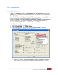
Case Study for GV-Hot Swap Recording Server System: Multi-Story Building with Retail Stores, Offices and Parking Lot Article ID: GV3-13-07-26-t Release Date: 07/26/2013 Table of Contents 1. 2. 3. 4. 5. Case Brief ........................................................................................................... 2 Suggested Installation....................................................................................... 3 Purchase List for the Suggested Installation .................................................. 4 Recommendations and Limitations for GV-Recording Server ....................... 7 4.1 Suggested Hard Disk Arrangement...........................................................................7 4.2 Recommended Hard Disk Brand ..............................................................................9 4.3 Network Requirements............................................................................................10 System Requirements for GV-Control Center................................................ 12 5.1 6. Setting Up Display on Multiple Monitors .................................................................13 Ethernet Cable Requirements ......................................................................... 15 1 1. Case Brief The client needed a surveillance solution to ensure the safety of a multi-story building. Floors 2 to 4 are offices, the first floor is a retail store, and the basement included a retail store and an employee parking lot. 24 GV-BX1200 Box Cameras were installed on each floor to make sure that all areas are covered. In addition, 2 GV-FE521 Fisheye Cameras and 4 GV-SD220 IP Speed Domes with PTZ capabilities were installed on the ground floor to monitor the entrances of the retail store. In the basement floor, the underground parking lot is secured by 2 GV-Hybrid LPR Cameras designed to clearly capture vehicle license plates. In the basement, a security control room was set up to house a 20-bay GV-Hot Swap Recording Server System, which receives and records all 128 IP channels installed in the building, and can transmit videos to the GV-Control Center. The security staff can then use the Matrix View of GV-Control Center to simultaneously watch live view of the 128 GV-IP Cameras. Multiple monitors were installed to simultaneously watch the 128 channel live view and one monitor was set up for applications such as E-Map and Remote ViewLog. Also located in the security room is a GV-Hot Swap LPR system (GV-ASManager and GV-DVR LPR) capable of recognizing the vehicle license plates detected in the video from the two GV-Hybrid LPR Cameras. Access can be granted when the detected license plate numbers match the vehicles registered in GV-ASManager's employee database. 2 2. Suggested Installation GV-BX1200 x 24 GV-PoE2401 Office GV-BX1200 x 24 GV-PoE2401 Office GV-BX1200 x 24 GV-PoE2401 Office GV-PoE2401 GV-BX1200 x 24 GV-SD220 x 4 GV-PoE0800 GV-FE521 x 2 Retail GV-Control Center Multiple monitors 4 ports Gigabit Switch GV-Hot Swap Recording Server System GV-Hybrid LPR Cam x 2 GV-PA481 x 2 GV-PoE2401 GV-BX1200 x 24 Parking GV-Hot Swap LPR System Retail 16 ports Gigabit Switch 3 3. Purchase List for the Suggested Installation GeoVision Products Floor Products Quantity Note 4th Floor GV-BX1200 24 GV-PoE2401 Switch 1 24 PoE ports, 2 Gigabit TP/SFP Combo Uplink ports 3rd Floor GV-BX1200 24 GV-PoE2401 Switch 1 24 PoE ports, 2 Gigabit TP/SFP Combo Uplink ports 2nd Floor GV-BX1200 24 GV-PoE2401 Switch 1 24 PoE ports, 2 Gigabit TP/SFP Combo Uplink ports 1st Floor GV-BX1200 24 GV-FE521 2 GV-SD220 4 GV-PoE2401 Switch 1 24 PoE ports, 2 Gigabit TP/SFP Combo Uplink ports B1 GV-PoE0800 Switch 1 8 PoE ports GV-Hot Swap Recording Server System 1 3 Gigabit Ethernet ports - 4U, 20-Bay PC GV-Control Center s/w 1 GV-Control Center Dongle 1 GV-Keyboard with Joystick 1 GV-BX1200 24 GV-Hybrid LPR Camera 2 For Control Center Comes with GV-PA481 PoE Adaptor GV-Hot Swap LPR System - 3U, 8-Bay 1 2 Gigabit Ethernet ports 1 24 PoE ports, 2 Gigabit (GV-ASManager + GV-DVR LPR) GV-PoE2401 Switch TP/SFP Combo Uplink ports 4 Non-GeoVision Products Floor Products 4th Floor Network Cable Quantity Details 25 1. Cat 5e x 24 (GV-BX1200 to GV-PoE2401) 2. Cat 6 x 1 (GV-PoE2401 to 16 ports Gigabit Switch) 3rd Floor Network Cable 25 1. Cat 5e x 24 (GV-BX1200 to GV-PoE2401) 2. Cat 6 x 1 (GV-PoE2401 to 16 ports Gigabit Switch) 2nd Floor Network Cable 25 1. Cat 5e x 24 (GV-BX1200 to GV-PoE2401) 2. Cat 6 x 1 (GV-PoE2401 to 16 ports Gigabit Switch) 1st Floor Network Cable 32 1. Cat 5e x 24 (GV-BX1200 to GV-PoE2401) 2. Cat 5e x 2 (GV-FE521 to GV-PoE0800) 3. Cat 5e x 4 (GV-SD220 to GV-PoE0800) 4. Cat 6 x 1 (GV-PoE0800 to 16 ports Gigabit Switch) 5. Cat 6 x 1 (GV-PoE2401 to 16 ports Gigabit Switch) B1 7200 rpm hard disk 20 For recording videos on GV-Recording Server PC 1 For installing GV-Control Center. Refer to the section below for PC specifications. Monitor 6 or 9 For watching 128 ch live view using GV-Control Center Gigabit Switch 2 - 16 Ports Gigabit Switch to connect: GV-PoE2401 x 5 GV-Recording Server x 1 GV-Hot Swap LPR System x 1 GV-Hybrid LPR Camera x 2 - 4 Ports Gigabit Switch to connect: GV-Hot Swap Recording Server System x 1 GV-Control Center x 1 5 Floor Products B1 Network Cable Quantity 33 Details - IP Camera 1. Cat 5e x 24 (GV-BX1200 to GV-PoE2401) 2. Cat 6 x 1 (GV-PoE2401 to 16 ports Gigabit Switch) - LPR System 3. Cat 5e x 2 (GV-Hybrid LPR Camera to GV-PA481) 4. Cat 5e x 2 (GV-PA481 to 16 ports Gigabit Switch) 5. Cat 6 x 1 (GV-Hot Swap LPR System to 16 ports Gigabit Switch) - Recording Server 6. Cat 6 x 1 (GV-Hot Swap Recording Server System to 16 ports Gigabit Switch) 7. Cat 6 x 1 (GV-Hot Swap Recording Server System to 4 ports Gigabit Switch) 8. Cat 6 x 1 (GV-Control Center to 4 ports Gigabit Switch) 6 4. Recommendations and Limitations for GV-Recording Server 4.1 Suggested Hard Disk Arrangement This section describes how to arrange 20 2TB hard disks for recording in the 20-bay GV-Hot Swap Recording Server System, under Round-the-Clock Mode and Motion Detection Mode. Note: To see how to set up storage groups and assign hard disks in the GV-Recording Server software, refer to p. 17 in GV-Recording Server User’s Manual: http://ftp.geovision.tw/FTP/Support/Recording Server/V1200/GV-Recording Server User Manual(RSV12-A-EN).zip Round-the-Clock Mode When using Round-the-Clock recording mode, you can divide the 128 channels into 5 storage groups, with 1 storage group for each floor. Next, assign 4 hard disks to each storage group. The table below shows the number of days you can record in 20 2TB hard disks under Round-the-Clock mode. In this example, the 4 GV-SD220 cameras installed on the 1st floor were distributed to storage groups 2 and 3 to avoid overloading the hard disks. Every storage group evenly included 26 cameras and 4 hard disks, except for Group 1 with only 24 cameras. Storage Group Camera Hard Disk Recording Capacity Group 1 4F: GV-BX1200 x 24 HDD 1 ~ 4 At least 8 days of data HDD 5 ~ 8 At least 8 days of data HDD 9 ~ 12 At least 8 days of data HDD 13 ~ 16 At least 8 days of data HDD 17 ~ 20 At least 8 days of data Group 2 Group 3 Group 4 Group 5 3F: GV-BX1200 x 24 1F: GV-SD220 x 2 2F: GV-BX1200 x 24 1F: GV-SD220 x 2 1F: GV-BX1200 x 24 1F: GV-FE521 x 2 B1: GV-BX1200 x 24 B1: Hybrid LPR Camera x 2 Note: The data is based on calculation from the GV-IP Camera Bandwidth and Recording Size Calculator: http://www.geovision.com.tw/english/Bandwidth.asp 7 Motion Detection Mode When recording upon Motion Detection, assign no more than 10 channels to each hard disk to ensure stability. The table below shows the number of days you can record in 20 2TB hard disks when using Motion Detection mode. In this example, since the 20 hard disks cannot be evenly distributed among 13 storage groups, some storage groups will be assigned 1 hard disk while other storage groups will be assigned 2 hard disks. The number of hard disks assigned for a storage group may depend on the actual environments. You may assign more hard disks to the group that would have more motion events. Storage Group Camera Hard Disk Recording Capacity Group 1 4F: GV-BX1200 x 10 HDD 1 ~ 2 At least 22 days of data Group 2 4F: GV-BX1200 x 10 HDD 3 ~ 4 At least 22 days of data HDD 5 ~ 6 At least 22 days of data HDD 7 ~ 8 At least 22 days of data HDD 9 ~ 10 At least 22 days of data Group 3 Group 4 Group 5 4F: GV-BX1200 x 4 3F: GV-BX1200 x 6 3F: GV-BX1200 x 10 3F: GV-BX1200 x 8 2F: GV-BX1200 x 2 Group 6 2F: GV-BX1200 x 10 HDD 11 ~ 12 At least 22 days of data Group 7 2F: GV-BX1200 x 10 HDD 13 ~ 14 At least 22 days of data HDD 15 At least 11 days of data HDD 16 At least 11 days of data HDD 17 At least 11 days of data Group 8 Group 9 Group 10 2F: GV-BX1200 x 2 1F: GV-BX1200 x 8 1F: GV-BX1200 x 10 1F: GV-BX1200 x 6 B1: GV-BX1200 x 4 Group 11 B1: GV-BX1200 x 10 HDD 18 At least 11 days of data Group 12 B1: GV-BX1200 x 10 HDD 19 At least 11 days of data HDD 20 At least 11 days of data 1F: GV-SD220 x 4 Group 13 1F: GV-FE521 x 2 B1: Hybrid LPR Camera x 2 Note: 1. It is assumed that there are 500 motion events per day that each lasts 1 minute. 2. The data is based on calculation from the GV-IP Camera Bandwidth and Recording Size Calculator: http://www.geovision.com.tw/english/Bandwidth.asp 8 4.2 Recommended Hard Disk Brand To maintain system stability and to keep your recordings safe when using GeoVision software, we advise you to use any of the recommended and/or the tested hard disk drives listed below. Brand Series Seagate Barracuda (XT Series, ES.2 Series, 7200 Series) SV35 Series Constellation ES Series Hitachi Hitachi Series Western Digital Caviar Black Caviar Blue RE Series To find the tested hard disk models, see: http://pd.geovision.tw/technotice/Others/Recommended_HDD.pdf 9 4.3 Network Requirements In the recommended installation illustrated above, the GV-Recording Server receives video from the 128 GV-IP Cameras installed in the building, and then transmits the 128 IP channels to GV-Control Center. In this case, one Gigabit Ethernet port for the incoming 128 channels and one Gigabit Ethernet port for the outgoing 128 channels are sufficient. In addition, 2 PoE switches are applied to divide a local area network into two segments (receiving and transmitting) for efficient network. Note: GV-Hot Swap Recording Server System has three built-in Gigabit Ethernet ports with 3 default IP addresses: 192.168.0.200, 192.168.0.201 and 192.168.0.202 with the same subnet mask 255.255.252.0. However, if you are not following the recommended installation (Ex: more outgoing channels or higher resolution cameras or no PoE switches used to divide the network traffic), you may need to set up additional Gigabit connections to avoid network bottleneck. The numbers of Gigabit network cards required to receive 128 channels and transmit 300 channels are listed below according to the resolution of the source video. Gigabit Network Cards Required Resolution FPS Codec Receiving 128 ch 1.3 MP 2.0 MP 3.0 MP 30 fps 30 fps 20 fps Transmitting 300 ch Gigabit network card x 1 Gigabit network card x 2 (up to 128 ch per card) (up to 150 ch per card) Gigabit network card x 2 Gigabit network card x 4 (up to 64 ch per card) (up to 75 ch per card) Gigabit network card x 1 Gigabit network card x 2 (up to 128 ch per card) (up to 150 ch per card) H.264 H.264 H.264 10 After installing the network cards needed, divide networks into multiple subnets or segments, and then organize IP channels received and clients transmitted into different networks. 1. Assign each network card to a different IP address and subnet mask. 2. Organize IP channels and clients into groups and then assign each group to different network cards using the IP addresses you have set up. 1 MP / 3 MP Source Video 2 MP Source Video Receiving Transmitting GigaLAN 3, 75 CH IP Video Devices GigaLAN 1, 64 CH GigaLAN 4, 75 CH GigaLAN 2, 64 CH GigaLAN 5, 75 CH GigaLAN 6, 75 CH GV-Recording Server + 6 Network Cards assigned on different networks 11 Clients 5. System Requirements for GV-Control Center For optimal performance, make sure the PC for installing GV-Control Center meets the following requirements. OS 64-bit Windows 7 / 8 / Server 2008 R2 / Server 2012 CPU Core i7 2600K, 3.4 GHz RAM 3 x 2 GB Hard Disk 1 GB Graphic Card AGP or PCI-Express, 1024 x 768, 32-bit color DirectX 9.0c LAN Card Gigabit Ethernet x 2 Hardware Internal or External GV-USB Dongle Notes for Graphic Cards: 1. The number of graphic cards required depends on the number of output ports supported by your graphic cards. For example, if your graphic card supports 3 output ports, you will need 3 graphic cards to set up 9 monitors. 2. If you are using more than two graphic cards on a server, make sure they are of the same brand, model and driver version to ensure maximum efficiency. 3. The following graphic cards have been tested for compatibility: ATI 5870 / 6770 / 7750 NVIDIA GeForce GTS450 / GTX 650 Ti 12 5.1 1. Setting Up Display on Multiple Monitors After the graphic cards are installed, go to Windows’ Screen Resolution setting in the Control Panel. The number of monitors detected will be displayed. 2. Drag the monitor icons and adjust the positions according to your actual monitor arrangement. 3. To simultaneously watch 128 channels, create multiple Matrix Views using one of the options below. a. 6 Monitors: Divide the 128 channels into 5 Matrix Views with 1 Matrix View for each floor. In this example, one Matrix View displays 24 to 30 channels depending on the number of cameras installed in each floor. The 6th monitor is used for applications such as E-Map and Remote ViewLog. b. 9 Monitors: Divide the 128 channels into 8 Matrix Views with 16-channel screen divisions for each Matrix View. The 9th monitor is used for applications such as E-Map and Remote ViewLog. Note: For details on assigning channels to Matrix View, refer the Matrix View section in GV-Control Center User’s Manual starting from p.74: http://ftp.geovision.tw/FTP/Support/CMS/control centerv3100/GV-Control Center User Manual(CCSV31-A-EN).zip 13 4. Next, click the Application Position function in GV-Control Center’s toolbar to define the content of every monitor. 5. Drag the icons of the Matrix Views and other applications on the bottom to the monitors. 14 6. Ethernet Cable Requirements When installing, each Ethernet cable cannot exceed 100 meters. In order for the PoE switches to deliver power without problem, it is recommended to use Cat 5 / 5e and Cat 6 cables. The high quality Ethernet cable reduces lost during power transmission. The wiring cable types are as below. 10BaseT: 2-pair UTP/STP Cat. 3, 4, 5 cable, EIA / TIA-568 100-ohm (Max. 100 m) 100BaseTX: 2-pair UTP/STP Cat. 5 cable, EIA / TIA-568 100-ohm (Max. 100 m) 1000BaseT: 4-pair UTP/STP Cat. 6 cable, EIA / TIA-568 100-ohm (Max. 100 m) 15