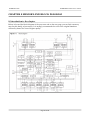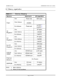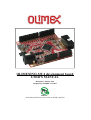
1
OLIMEXINO-32U4 development board
USER’S MANUAL
Revision G, January 2015
Designed by OLIMEX Ltd, 2013
All boards produced by Olimex LTD are ROHS compliant
OLIMEX© 2015
OLIMEXINO-32U4 user's manual
© 2015 Olimex Ltd. Olimex®, logo and combinations thereof, are registered trademarks of Olimex Ltd. Other product
names may be trademarks of others and the rights belong to their respective owners.
The information in this document is provided in connection with Olimex products. No license, express or implied
or otherwise, to any intellectual property right is granted by this document or in connection with the sale of
Olimex products.
This work is licensed under the Creative Commons Attribution-ShareAlike 3.0 Unported License. To view a copy of
this license, visit http://www.creativecommons.org/licenses/by-sa/3.0/.
This hardware design by Olimex LTD is licensed under a Creative Commons Attribution-ShareAlike 3.0 Unported
License.
The software is released under GPL.
It is possible that the pictures in this manual differ from the latest revision of the board.
The product described in this document is subject to continuous development and improvements. All particulars of the
product and its use contained in this document are given by OLIMEX in good faith. However all warranties implied or
expressed including but not limited to implied warranties of merchantability or fitness for purpose are excluded. This
document is intended only to assist the reader in the use of the product. OLIMEX Ltd. shall not be liable for any loss or
damage arising from the use of any information in this document or any error or omission in such information or any
incorrect use of the product.
This evaluation board/kit is intended for use for engineering development, demonstration, or evaluation purposes only
and is not considered by OLIMEX to be a finished end-product fit for general consumer use. Persons handling the
product must have electronics training and observe good engineering practice standards. As such, the goods being
provided are not intended to be complete in terms of required design-, marketing-, and/or manufacturing-related
protective considerations, including product safety and environmental measures typically found in end products that
incorporate such semiconductor components or circuit boards.
Olimex currently deals with a variety of customers for products, and therefore our arrangement with the user is not
exclusive. Olimex assumes no liability for applications assistance, customer product design, software performance, or
infringement of patents or services described herein.
THERE IS NO WARRANTY FOR THE DESIGN MATERIALS AND THE COMPONENTS
USED TO CREATE OLIMEXINO-32U4. THEY ARE CONSIDERED SUITABLE ONLY
FOR OLIMEXINO-32U4.
Page 2 of 28
OLIMEX© 2015
OLIMEXINO-32U4 user's manual
Table of Contents
CHAPTER 1 OVERVIEW......................................................................................... 5
1. Introduction to the chapter.......................................................................................................5
1.1 Features.....................................................................................................................................5
1.2 Similar boards..........................................................................................................................6
1.3 Organization.............................................................................................................................6
CHAPTER 2 INTRODUCTION TO ARDUINO..................................................... 7
2. What is Arduino?.......................................................................................................................7
2.1 First steps with Arduino IDE..................................................................................................8
CHAPTER 3 SETTING UP THE OLIMEXINO-32U4 BOARD.........................10
3. Introduction to the chapter.....................................................................................................10
3.1 Electrostatic warning.............................................................................................................10
3.2 Requirements......................................................................................................................... 10
3.3 Powering the board................................................................................................................10
3.4 Prebuilt software....................................................................................................................10
CHAPTER 4 OLIMEXINO-32U4 BOARD DESCRIPTION............................... 11
4. Introduction to the chapter..................................................................................................... 11
4.1 Layout (top view)................................................................................................................... 11
CHAPTER 5 THE ATMEGA32U4 MICROCONTROLLER..............................12
5. Introduction to the chapter.....................................................................................................12
5.1 The microcontroller's features..............................................................................................12
CHAPTER 6 CONTROL CIRCUITY.................................................................... 14
6. Introduction to the chapter.....................................................................................................14
6.1 Reset........................................................................................................................................14
6.2 Clock....................................................................................................................................... 14
CHAPTER 7 HARDWARE......................................................................................15
7. Introduction to the chapter.....................................................................................................15
7.1 Battery connector...................................................................................................................15
7.2 ICSP pin holes........................................................................................................................ 15
7.3 UEXT...................................................................................................................................... 16
7.4 Arduino shield pin holes........................................................................................................17
7.5 USB mini connector...............................................................................................................18
7.6 Jumper description................................................................................................................18
7.7 Additional hardware components........................................................................................ 19
CHAPTER 8 MEMORY AND BLOCK DIAGRAM.............................................20
8. Introduction to the chapter.....................................................................................................20
8.1 Memory organization............................................................................................................ 21
CHAPTER 9 SCHEMATICS...................................................................................22
Page 3 of 28
OLIMEX© 2015
OLIMEXINO-32U4 user's manual
9. Introduction to the chapter.....................................................................................................22
9.1 Eagle schematic......................................................................................................................22
9.2 Physical dimensions...............................................................................................................24
CHAPTER 10 REVISION HISTORY.....................................................................25
10. Introduction to the chapter...................................................................................................25
10.1 Document revision............................................................................................................... 25
10.2 Board revision...................................................................................................................... 26
10.3 Web page of your device......................................................................................................27
10.4 Warranty and returns..........................................................................................................28
Page 4 of 28
OLIMEX© 2015
OLIMEXINO-32U4 user's manual
CHAPTER 1 OVERVIEW
1. Introduction to the chapter
Thank you for choosing the OLIMEXINO-32U4 development board from Olimex! This document
provides a User’s Guide for the Olimex OLIMEXINO-32U4 development board. As an overview,
this chapter gives the scope of this document and lists the board’s features. The document’s
organization is then detailed.
The OLIMEXINO-32U4 development board enables code development of applications running on
the ATmega32U4 microcontroller, manufactured by Atmel Corporation.
1.1 Features
•
•
•
•
•
•
•
•
•
•
•
•
•
•
•
Leonardo design – no FTDI chip, the MCU directly handles the virtual COM
ATMEGA32U4 microcontroller, all in one USB communication no need for external FTDI
chip.
Input power supply 7-12VDC
ULTRA LOW POWER voltage regulators and the consumption is only few microamps,
which enables hand-held and battery powered applications.
Li-Ion rechargeable battery power supply option with BUILD-IN on board charger, so when
you attach battery it is automatically charged and kept in this state until the other power
source (USB or external adapter) is removed and it AUTOMATICALLY will power the
board – no jumpers, no switches!
Works both on 3.3V and on 5V which is selectable with jumper, so 3.3V and 5V shields can
be used
UEXT connector which allow many existing modules like RF, ZIGBEE, GSM, GPS to be
connected
Allows RTC – Real Time Clock (Q1 can be replaced by RTC).
NOISE IMMUNE design
the LEDs and the button BUT are on the edge of the board so there is easy access even if the
boards have shields on them
all components are LOWER than the connectors, so the shields do not interference with
them
mini USB connector is used -it is common and used in most cell phones, so you don't have
to buy other cables
Original design had a flaw – the connectors were not spaced at 0.1" which made bread board
use impossible, to keep the compatibility we have the original spacing but we also added a
0.1'' connector which customer can use with bread boards (and jumper wires) saving the
hustle of soldering
All signals on the connectors are printed on top of the board, so when you check with probe
you know exactly which port you are measuring
4 mount holes make board attachment easier
Page 5 of 28
OLIMEX© 2015
OLIMEXINO-32U4 user's manual
1.2 Similar boards
OLIMEXINO-32U4 is an ARDUINO-LEONARDO-like board with ATmega32U4.
It is a powerful board considering its low price but yet a starter board for the Arduino family.
The more powerful Arduino board we have in the range is OLIMEXINO-328 – based on Arduino
Duemilanove. It has a more sophisticated supply circuit, USB OTG connector and there are more
Arduino projects available.
1.3 Organization
Each section in this document covers a separate topic, organized as follow:
– Chapter 1 is an overview of the board usage and features
– Chapter 2 has a short introduction to Arduino platform and its derivatives Pinguino and
Maple
– Chapter 3 provides a guide for quickly setting up the board
– Chapter 4 contains the general board diagram and layout
– Chapter 5 describes the component that is the heart of the board: the ATmega32U4
microcontroller
– Chapter 6 is an explanation of the control circuitry associated with the microcontroller to
reset. Also shows the clocks on the board
– Chapter 7 covers the connector pinout, peripherals and jumper description
– Chapter 8 shows the processor diagram and memory map
– Chapter 9 provides the schematics
– Chapter 10 contains the revision history
Page 6 of 28
OLIMEX© 2015
OLIMEXINO-32U4 user's manual
CHAPTER 2 INTRODUCTION TO ARDUINO
2. What is Arduino?
Arduino is an open-source electronics prototyping platform, designed to make the process of using
electronics in multidisciplinary projects easily accessible. The hardware consists of a simple open
hardware design for the Arduino board with an Atmel AVR processor and on-board I/O support. The
software consists of a standard programming language and the boot loader that runs on the board.
Arduino hardware is programmed using a Wiring-based language (syntax + libraries), similar to C+
+ with some simplifications and modifications, and a Processing-based Integrated Development
Environment (IDE).
The project began in Ivrea, Italy in 2005 aiming to make a device for controlling student-built
interaction design projects less expensively than other prototyping systems available at the time. As
of February 2010 more than 120,000 Arduino boards had been shipped. Founders Massimo Banzi
and David Cuartielles named the project after a local bar named Arduino. The name is an Italian
masculine first name, meaning "strong friend". The English pronunciation is "Hardwin", a
namesake of Arduino of Ivrea.
More information could be found at the creators web page http://arduino.cc/ and in the Arduino
Wiki http://en.wikipedia.org/wiki/Arduino
To make the story short – Arduino is easy for beginners who lack Electronics knowledge, but also
does not restrict professionals as they can program it in C++ or mix of Arduino/C++ language.
There are thousands of projects which makes it easy to startup as there is barely no field where
Arduino enthusiasts to have not been already.
Arduino has inspired two other major derivatives – MAPLE and PINGUINO. Based on 8-bit AVR
technology the computational power of Arduino boards is modest, this is why a team from MIT
developed the MAPLE project which is based on ARM7 STM32F103RBT6 microcontroller. The
board has same friendly IDE as Arduino and offers the same capabilities as hardware and software
but runs the Arduino code much faster. The Maple project can be found at http://leaflabs.com
In parallel with Arduino another project was started called PINGUINO. This project chose its first
implementation to be with PIC microcontrollers, as AVRs were hard to find in some parts of the
world like South America so it is likely to see lot of PINGUINO developers are from that part of the
world. PINGUINO project founders decided to go with Python instead Java for processing
language. For the moment PINGUINO is much more flexible than Arduino as it is not limited to
8bit microcontrollers. Currently the IDE, which has GCC in background, can support 8-bit PIC
microcontrollers, 32bit PIC32 (MIPS) microcontrollers and ARM7/CORTEXM3 microcontrollers
which makes PINGUINO very flexible because once you make your project you can migrate easily
through different hardware platforms and not being bound to a single microcontroller manufacturer.
The PINGUINO project can be found at: http://www.pinguino.cc.
Page 7 of 28
OLIMEX© 2015
OLIMEXINO-32U4 user's manual
2.1 First steps with Arduino IDE
Depending when you purchased the board there are two scenarios since the PID (product ID) which
is stored in the firmware and expected by the IDE is different between versions 1.0.0 and 1.0.1
(1.0.1 is the first release of the Arduino IDE with official support for Leonardo).
2.1.1 For purchases after the official release of Leonardo
Boards produced after the official release of Arduino Leonardo have the latest bootloader available
with the adjusted bootloader PID. Download the latest Arduino IDE and extract the package. You
can find the needed driver for the bootloader located in folder /drivers. You click update on the
device in device manager and point the installer to the /drivers folder.
Then launch Arduino IDE and set the correct board and COM port in TOOLS menu.
From File->Open navigate to the examples folder which is found in the Arduino IDE installation
folder. Choose a simple example to begin with like BlinkWithoutDelay.ino and open it. Click verify
and after it compiles click “Upload”. Voila, you have uploaded code to your Arduino device.
Now start exploring the world of Arduino! More info and help on the software can be found and the
official Arduino web site: http://www.arduino.cc/.
2.1.2 For purchases before the official release of Leonardo
If you have purchased the OLIMEXINO-32U4 before the official release of the Arduino Leonardo
board there are two scenarios for using Arduino IDE:
1) Download Arduino IDE 1.0 RC2 or Arduino IDE 1.0.0. When you extract the package check if
the Arduino Leonardo section is the \hardware\arduino\boards is uncommented. If the section has
number signs (#) infront remove the number signs (#).
2) If you want to use the latest version (which by the time of writing is 1.0.1) you would need to
change to bootloader firmware. This will require an AVR programmer tool.
You can get the bootloader in .elf format from our web site. You can also use the original bootloader
hex if you set the fuses and lock bits for the processor as follows:
low_fuses=0xff
high_fuses=0xd8
extended_fuses=0xcb
lock_bits (choose “SPM Prohibited in Boot Section”) from the drop down menu which will set the
bits either to EF or 2F)
After you have downloaded and extracted the desired IDE you need to install the driver for your
operating system. You can find the needed driver for the bootloader located in folder /drivers. You
click update on the device in device manager and point the installer to the /drivers folder.
Then launch Arduino IDE and set the correct board and COM port in TOOLS menu.
Page 8 of 28
OLIMEX© 2015
OLIMEXINO-32U4 user's manual
From File->Open navigate to the examples folder which is found in the Arduino IDE installation
folder. Choose a simple example to begin with like BlinkWithoutDelay.ino and open it. Click verify
and after it compiles click “Upload”. Voila, you have uploaded code to your Arduino device.
Now start exploring the world of Arduino! More info and help on the software can be found and the
official Arduino web site: http://www.arduino.cc/.
Page 9 of 28
OLIMEX© 2015
OLIMEXINO-32U4 user's manual
CHAPTER 3 SETTING UP THE OLIMEXINO-32U4 BOARD
3. Introduction to the chapter
This section helps you set up the OLIMEXINO-32U4 development board for the first time.
Please consider first the electrostatic warning to avoid damaging the board, then discover the
hardware and software required to operate the board. The procedure to power up the board is given,
and a description of the default board behavior is detailed.
3.1 Electrostatic warning
OLIMEXINO-32U4 is shipped in a protective anti-static package. The board must not be exposed
to high electrostatic potentials. A grounding strap or similar protective device should be worn when
handling the board. Avoid touching the component pins or any other metallic element.
3.2 Requirements
In order to set up the OLIMEXINO-32U4, the following items are required:
If using the free ARDUINO IDE the ONLY requirement is a miniUSB to USB-A cable to connect
to a computer.
If you want to upgrade the bootloader, or program the board without the ARDUINO-IDE there are
pinouts for ICSP programmer (note that there isn't a connector mounted). You can use our AVRISP-MK2, or AVR-ISP500 programmer for custom programming without ARDUINO IDE.
Having an AVR programmer is highly advisable since the bootloader software is still not perfect
and it is possible to destroy it only by software means (remap pins used for programming) which
would require reinstalling the bootloader.
3.3 Powering the board
The OLIMEXINO-32U4 board is self-powered by the miniUSB if it is connected to a USB hub of a
computer. Alternatively, it can be powered via the POWER JACK by 7Vdc to 12Vdc or via the
3.7V-LI_BAT connector by 3.7V battery.
The bootloader starts automatically.
On powering the board PWR_LED should turn on. RXLED and TXLED should turn on and
monitor the send receive on the virtual COM port. LED1 and LED2 should start blinking.
3.4 Prebuilt software
The board comes with prebuilt ARDUINO bootloader. The different part between the other
Arduinos and Leonardo is that Leonardo doesn't use FTDI chip nor external chip for the virtual
COM port but it is handled by the ATmega32U4.
Page 10 of 28
OLIMEX© 2015
OLIMEXINO-32U4 user's manual
CHAPTER 4 OLIMEXINO-32U4 BOARD DESCRIPTION
4. Introduction to the chapter
Here you get acquainted with the main parts of the board. Note the names used on the board differ
from the names used to describe them. For the actual names check the OLIMEXINO-32U4 board
itself.
4.1 Layout (top view)
Page 11 of 28
OLIMEX© 2015
OLIMEXINO-32U4 user's manual
CHAPTER 5 THE ATMEGA32U4 MICROCONTROLLER
5. Introduction to the chapter
In this chapter is located the information about the heart of OLIMEXINO-32U4 – its
microcontroller. The information is a modified version of the datasheet provided by its
manufacturers.
5.1 The microcontroller's features
• High Performance, Low Power AVR® 8-Bit Microcontroller
• Advanced RISC Architecture
– 135 Powerful Instructions – Most Single Clock Cycle Execution
– 32×8 General Purpose Working Registers
– Fully Static Operation
– Up to 16 MIPS Throughput at 16 MHz
– On-Chip 2-cycle Multiplier
• Non-volatile Program and Data Memories
– 32K Bytes of In-System Self-Programmable Flash
– 2.5K Bytes Internal SRAM
– 1K Bytes Internal EEPROM
– Write/Erase Cycles: 10,000 Flash/100,000 EEPROM
– Data retention: 20 years at 85°C/ 100 years at 25°C(1)
– Optional Boot Code Section with Independent Lock Bits
In-System Programming by On-chip Boot Program
True Read-While-Write Operation
All supplied parts are preprogramed with a default USB bootloader
– Programming Lock for Software Security
• JTAG (IEEE std. 1149.1 compliant) Interface
– Boundary-scan Capabilities According to the JTAG Standard
– Extensive On-chip Debug Support
– Programming of Flash, EEPROM, Fuses, and Lock Bits through the JTAG
Interface
• USB 2.0 Full-speed/Low Speed Device Module with Interrupt on Transfer Completion
– Complies fully with Universal Serial Bus Specification Rev 2.0
– Supports data transfer rates up to 12 Mbit/s and 1.5 Mbit/s
– Endpoint 0 for Control Transfers: up to 64-bytes
– 6 Programmable Endpoints with IN or Out Directions and with Bulk, Interrupt or
Isochronous Transfers
– Configurable Endpoints size up to 256 bytes in double bank mode
– Fully independent 832 bytes USB DPRAM for endpoint memory allocation
– Suspend/Resume Interrupts
– CPU Reset possible on USB Bus Reset detection
– 48 MHz from PLL for Full-speed Bus Operation
– USB Bus Connection/Disconnection on Microcontroller Request
– Crystal-less operation for Low Speed mode
• Peripheral Features
Page 12 of 28
OLIMEX© 2015
OLIMEXINO-32U4 user's manual
– On-chip PLL for USB and High Speed Timer: 32 up to 96 MHz operation
– One 8-bit Timer/Counter with Separate Prescaler and Compare Mode
– Two 16-bit Timer/Counter with Separate Prescaler, Compare- and Capture Mode
– One 10-bit High-Speed Timer/Counter with PLL (64 MHz) and Compare Mode
– Four 8-bit PWM Channels
– Four PWM Channels with Programmable Resolution from 2 to 16 Bits
– Six PWM Channels for High Speed Operation, with Programmable Resolution from
2 to 11 Bits
– Output Compare Modulator
– 12-channels, 10-bit ADC (features Differential Channels with Programmable Gain)
– Programmable Serial USART with Hardware Flow Control
– Master/Slave SPI Serial Interface
– Byte Oriented 2-wire Serial Interface
– Programmable Watchdog Timer with Separate On-chip Oscillator
– On-chip Analog Comparator
– Interrupt and Wake-up on Pin Change
– On-chip Temperature Sensor
• Special Microcontroller Features
– Power-on Reset and Programmable Brown-out Detection
– Internal 8 MHz Calibrated Oscillator
– Internal clock prescaler & On-the-fly Clock Switching (Int RC / Ext Osc)
– External and Internal Interrupt Sources
– Six Sleep Modes: Idle, ADC Noise Reduction, Power-save, Power-down, Standby, and
Extended Standby
• I/O and Package
– All I/O combine CMOS outputs and LVTTL inputs
– 26 Programmable I/O Lines
– 44-lead QFN Package, 7×7mm
• Operating Voltages
– 2.7 – 5.5V
• Operating temperature
– Industrial (-40°C to +85°C)
• Maximum Frequency
– 8 MHz at 2.7V – Industrial range
– 16 MHz at 4.5V – Industrial range
For comprehensive information on the microcontroller visit the Atmel web page for a datasheet.
At the moment of writing the microcontroller datasheet can be found at the following link:
http://www.atmel.com/Images/doc7766.pdf
Page 13 of 28
OLIMEX© 2015
OLIMEXINO-32U4 user's manual
CHAPTER 6 CONTROL CIRCUITY
6. Introduction to the chapter
Here you can find information about reset circuit, power circuit and quartz crystal locations.
6.1 Reset
OLIMEXINO-32U4 reset circuit includes R7 (4.7kΩ), R8 (330Ω), D1 (Shottky diode),
ATmega32U4 pin 13 (#RESET) and a RESET button. Note that it also can be found at the ICSP
header pin 5 and power connector pin 1.
6.2 Clock
16MHz quartz crystal Q1 is found at pins 16 and 17 of the processor.
By default OLIMEXINO-32U4 operates at 5V, which allows the main microcontroller
(ATmega32u4) to operate properly at the maximum clock speed (16 MHz). The ATmega32u4
would work properly at 16MHz only if powered by at least 4.5V.
If you decide to change the position of the jumper 3.3V/5V jumper to 3.3V position, please note
that, at 3.3V, the maximum frequency that can be achieved with ATmega32u4 is around 10MHz,
thus the 16MHz operation is a significant overclock. Yet, our tests proved that the board works
reliably with a 16MHz qaurtz even at 3.3V.
IMPORTANT: If the board has a quartz crystal rotated at 45 degrees relative to the pads provided
do not panic. This is normal. We have two types of such crystals – one of them requires 4 pads, the
other only 2 pads. That is why we have provided 4 pads to be able to fit both crystals. All boards
Olimex manufactures pass automatized optical inspection after assembly and obvious misplacement
like this is impossible to occur.
Page 14 of 28
OLIMEX© 2015
OLIMEXINO-32U4 user's manual
CHAPTER 7 HARDWARE
7. Introduction to the chapter
In this chapter are presented the connectors that can be found on the board all together with their
pinout. Jumpers functions are described. Notes and info on specific peripherals are presented. Notes
regarding the interfaces are given.
7.1 Battery connector
The battery connector is suitable for 3.7V LiPo batteries. The board has a built-in charger circuit, so
when the main power supply is restored the battery would get recharged automatically.
Pin #
Signal Name
1
VBAT
2
GND
7.2 ICSP pin holes
The 6 pin ICSP header provides interface for custom programming/debugging outside of the
Arduino IDE. Note the pin holes doesn't have a connector mounted over – you have to mount
it/solder it yourself. The pinout can be found in the table below. It is important to check the jumper
configuration for proper use of the ICSP pin hole.
ICSP pin holes
Pin #
Signal name
Pin #
Signal name
1
D14(MISO)
4
D16(MOSI)
2
Vcc
5
RESET
3
D15(SCK)
6
GND
Page 15 of 28
OLIMEX© 2015
OLIMEXINO-32U4 user's manual
7.3 UEXT
OLIMEXINO-32U4 board has UEXT connector and can interface Olimex's UEXT modules.
For more information on our UEXT modules please visit:
https://www.olimex.com/Products/Modules/UEXT/
Pin #
Signal name
1
+3.3V
2
GND
3
D1(TXD)
4
D0(RXD)
5
D3(SCL)
6
D2(SDA)
7
D14(MISO)
8
D16(MOSI)
9
D15(SCK)
10
D13(UEXT_#CS)
It is important to note that there are 4.7k pull-up resistors on the I2C lines – SCL/SDA (D3 and D2
respectively). You can disconnect/disable the resistors by cutting between the pads of the small
SMT jumpers R11_E and R12_E.
The chip select pin – CS (D13) also has a 4.7k pull-up resistor which might be disabled by cutting
R13_E.
Page 16 of 28
OLIMEX© 2015
OLIMEXINO-32U4 user's manual
7.4 Arduino shield pin holes
For your convenience the pads are named individually near each of them. Please take extra care
about the numbering but consider that there might be offset.
Pad Name
Signal
Pad Name
POWER CON1
Signal
DIGITAL CON2
RST
RESET
A0
PF7/ADC7/TDI
3V3
+3.3 V
A1
PF6/ADC6/TDO
5V
+5 V
A2
PF5/ADC5/TMS
GND
GROUND
A3
PF4/ADC4/TCK
GND
GROUND
A4
PF1/ADC1
VIN
V in
A5
PF0/ADC0
DIGITAL CON3
DIGITAL CON4
D0(RXD)
PD2/RXD1/INT2
D8(UEXT_PWR_E)
D1(TXD)
PD3/TXD1/INT3
D9(LED2)
D2(SDA)
PD1/SDA/INT1
D10
PB6/PCINT6/OC1B/OC4B/ADC
13
D3(SCL)
PD0/OC0B/SCL/
INT0
D11
PB7/PCINT7/OC0A/OC1C/
#RTS
D4
PD4/ICP1/ADC8
D12
PD6/T1/#OC4D/ADC9
D5
PC6/OC3A/
#OC4A
D13(UEXT_#CS)
PC7/ICP3/CLK0/OC4A
D6
PD7/T0/OC4D/A
DC10
GND
GND
D7(LED1)
INT6/AIN0/PE6
AREF
AREF
SDA
D2(SDA)
SCL
D3(SCL)
Page 17 of 28
RB4/PCINT4/ADC11
PB5/PCIN5/OC1A/#OC4B/
ADC12
OLIMEX© 2015
OLIMEXINO-32U4 user's manual
7.5 USB mini connector
Note that the USB is configured only as device.
Pin #
Signal Name
1
+5V
2
D-
3
D+
4
Not connected
5
GND
7.6 Jumper description
3.3V/5V
This jumper controls whether the board is powered by 3.3Vdc source or 5Vdc.
Default position is 2-3 – 5Vdc.
AGND_E
When closed enables analog GND. SMD jumper.
Default state is closed.
FET3_E
When closed connects D8 from Arduino shield connector to FET3 so you can control the power on
the UEXT by software means.
When open D8 becomes GPIO. This is a SMD type of jumper.
Default state is closed.
Page 18 of 28
OLIMEX© 2015
OLIMEXINO-32U4 user's manual
LED1_E
When closed enables LED1. SMD jumper.
Default state is closed.
LED2_E
When closed enables LED2. SMD jumper.
Default state is closed.
RXLED_E
When closed enables RXLED. SMD jumper.
Default state is closed.
TXLED_E
When closed enables TXLED. SMD jumper.
Default state is closed.
R11_E, R12_E, R13_E
When these jumpers are closed they enable 4.7k Ohm pull-up resistors on each of the I2C lines
(R11_E is responsible for the resistor of SCL line, R12_E – for the SDA line, R13_E – for the
UEXT_CS). SMD jumpers.
Default state for all three is closed.
7.7 Additional hardware components
The components below are mounted on the OLIMEXINO-32U4 board but are not discussed above.
They are listed here for completeness:
General-purpose button
2 general purpose LEDs
2 LEDs showing virtual port activity
Note that connectors on the CON1, CON2, CON3, CON4 are soldered/mounted.
Page 19 of 28
OLIMEX© 2015
OLIMEXINO-32U4 user's manual
CHAPTER 8 MEMORY AND BLOCK DIAGRAM
8. Introduction to the chapter
Below is located the block diagram of the processor and on the next page you can find a memory
map for this family of processors. It is strongly recommended to refer to the original datasheet
released by Atmel for ones of higher quality.
Page 20 of 28
OLIMEX© 2015
OLIMEXINO-32U4 user's manual
8.1 Memory organization
Page 21 of 28
OLIMEX© 2015
OLIMEXINO-32U4 user's manual
CHAPTER 9 SCHEMATICS
9. Introduction to the chapter
In this chapter are located the schematics describing logically and physically OLIMEXINO-32U4.
9.1 Eagle schematic
OLIMEXINO-32U4 schematic is visible for reference here. You should zoom the pdf for a better
view and also string search is available. You can also find a stand-alone pdf on the web page for
OLIMEXINO-32U4 at our site: https://www.olimex.com/Products/Duino/AVR/OLIMEXINO32U4/. They are located in HARDWARE section.
This work is licensed under the Creative Commons Attribution-ShareAlike 3.0 Unported License.
To view a copy of this license, visit http://creativecommons.org/licenses/by-sa/3.0/.
The EAGLE schematic is situated below for quicker reference.
Page 22 of 28
OLIMEX© 2015
OLIMEXINO-32U4 user's manual
OLIMEXINO-32U4 Rev.A3
Designed by: OLIMEX LTD, BULGARIA
Web-address: https://www.OLIMEX.com
DVCC
AVCC
RESET
13
#RESET
AVCC
AVCC
14
VCC
34
C3
UVCC
6
C4
VBUS
5
USB
FB/600 OHM/1206(321611C-601)
VBUS
R1
R2
DD+
GND
C9 20pF
ID
Q1
16
GND
16.000MHz/SMD5x3.2/12pF
USB-MINI
C610nF
18
D12
D6
26
C10
100nF
A0
A1
A2
A3
A4
A5
1
A4
6
A5
1
D0
2
D1
3
D2
4
D3
5
D4
6
D5
7
D6
8
D7
D8(UEXT_PWR_E)
D9(LED2)
D10
D11
D12
D13(UEXT_#CS)
D17(RXLED)
D15(SCK)
PD5/XCK1/CTS
PB6/PCINT6/OC1B/OC4B/ADC13
D10
30
PB7/PCINT7/OC0A/OC1C/#RTS
D11
12
PD6/T1/#OC4D/ADC9
PD7/T0/OC4D/ADC10
1
D8
2
D9
3
D10
4
D11
5
D12
6
D13
7
AREF
D2(SDA)
D3(SCL)
GND
8
AREF
9
SDA
10
SCL
NA
This hardware design by Olimex LTD is licensed under a Creative Commons Attribution-ShareAlike 3.0 Unported License.
STAT LEDS
D7(LED1)
R9
D1
NA[1N5819(S4SOD-123)]
D9(LED2)
TXLED
ICSP
D17(RXLED)
D14(MISO)
D15(SCK)
RESET
4.7k
LED1_E
Close
#HWB
RESET
LED2_E
Close
RXLED_E
Close
R17
2k
C15
NA
R10
330R
DVCC
ICSP
1
2
3
4
5
6
D16(MOSI)
NA(HR2x3)
BUT
RST
R8
330R
A3
5
DVCC
4.7k
A2
4
1xPN1x10+1xPN1x8+2xPN1x6
DVCC
R7
A1
3
ATMEGA32U4-AU
BUTTONS
A0
2
D0(RXD)
D1(TXD)
D2(SDA)
D3(SCL)
D4
D5
D6
D7(LED1)
PB4/PCINT4/ADC11
D8(UEXT_PWR_E)
28
PB5/PCINT5/OC1A/#OC4B/ADC12
29
D9(LED2)
PD4/ICP1/ADC8
27
VIN
CON2
PB2/PDI/PCINT2/MOSI
D16(MOSI)
10
PB3/PDO/PCINT3/MISO
11
D14(MISO)
PD3/TXD1/INT3
22
GND
NA
D7(LED1)
#HWB
PB0/SS/PCINT0
8
PB1/PCINT1/SCLK
9
PD2/RXD1/INT2
25
GND
6
CON4
PD1/SDA/INT1
21
5V
5
NA
PD0/OC0B/SCL/INT0
20
3V3
3
XTAL1
19
RST
2
XTAL2
17
D3(SCL)
D2(SDA)
D0(RXD)
D1(TXD)
D4
TXLED
A5
A4
A3
A2
A1
A0
PLATFORM1
1
4
D+
GND
22R
22R
NA
D-
4
XTAL2
XTAL1
C8 20pF
L1
GND
3
PF0/ADC0
41
PF1/ADC1
40
INT6/AIN0/PE6
1
PE2/#HWB
33
GND
23
5V_USB
NA
PC7/ICP3/CLK0/OC4A
32
D13(UEXT_#CS)
PC6/OC3A/#OC4A
31
D5
GND
15
DD+
CON1
RESET
+5V
CON3
GND
43
DD+
R23
NA
UGND
35
AREF
PF6/ADC6/TDO
37
PF7/ADC7/TDI
36
UCAP
7
AREF 42
PF4/ADC4/TCK
39
PF5/ADC5/TMS
38
VCC
2
C2
R22
VIN
44
C5 1uF/10V
DVCC
3.3V
U1
5V_USB
24
C1
DVCC
R16
2k
R15
2k
R14
2k
C16
100nF
LED1
LED0603/GREEN
LED2
LED0603/YELLOW
TXLED
LED0603/GREEN
RXLED
LED0603/YELLOW
3.3V_E
DVCC
3.3V_E
UEXT
R19
0R(Board_Mounted)
3.3V_E
3.3V_E
0R
FET3
IRLML6402
R11_E
Close
VIN
5V_USB
+5V
3.3V/5V
HR1x3(3.3V:Open/5V:Close)
CHG_D
1
2
open
7-12VDC
PWR
D2
1N5819(S4SOD-123)
1N5819(S4SOD-123)
IN
OUT
ADJ/GND
+5V
YDJ-1136
R5
2k
4
C17
VDD
BATTERY
CHARGER
R4
AVCC
1
2
VSS
L2
22uH/10%/5mA
GND
R21
10k
2
4.7k
VBAT
3
VBAT
R6
10k
CE 1
PROG
5
1
C18
15k
C22
10uF/6.3V
2
3.7V-LI_BAT
DW02R
-
C20
100nF
C21
10uF/6.3V
AGND_E
1
2
CLOSE
appr. 70 mA charge current
This hardware design by Olimex LTD is licensed under a Creative Commons Attribution-ShareAlike 3.0 Unported License.
Page 23 of 28
1
FET3_E
D8(UEXT_PWR_E)
Close
UEXT
1
2
3
4
5
6
7
8
9
10
BH10R
330R/1%
R18
C19
1uF/10V
D1(TXD)
D3(SCL)
D14(MISO)
D15(SCK)
MCP73812T-420I/OT
R3
100R/1%
+5V
R11
DVCC
VIN
VOUT 3
U2
5.375V
+5V
MCP1700T-3302E/MB
2
Battery Charger
VR1(5.0V)
AMS1117-ADJ
3.3V
VR2(3.3V)
D3
FET1
IRLML6402
R12_E
Close
R13_E
Close
R12
R13
4.7k
4.7k
R20
100k
POWER_SUPPLY
+5V
D0(RXD)
D2(SDA)
D16(MOSI)
D13(UEXT_#CS)
OLIMEX© 2015
OLIMEXINO-32U4 user's manual
9.2 Physical dimensions
Note that all dimensions are in inches.
Page 24 of 28
OLIMEX© 2015
OLIMEXINO-32U4 user's manual
CHAPTER 10 REVISION HISTORY
10. Introduction to the chapter
In this chapter you will find the current and the previous version of the document you are reading.
Also the web-page for your device is listed. Be sure to check it after a purchase for the latest
available updates and examples.
10.1 Document revision
Revision
Changes
Modified
Pages
Initial
Initial release
All
B
C
Manual adjusted for Arduino IDE version 1.0.1
Fixed links
Adjusted formatting, fixed some mistakes, updated
links
8, 9, 15
All
Added info about the I2C
Updated disclaimer and warranty pages
D
ICSP and UEXT connector changes due to new
schematics
2, 15, 16,
17, 20, 22,
26, All
Adjusted formatting, fixed some mistakes
Fixed - “the LEDs and the BUTTONs are on the edge
of the board so there is easy access even if the boards
have shields on them” - not true for RST button
E
Fixed - “All signals on the connectors are printed on
top and on bottom of the board, so when you check
with probe you know exactly which port you are
measuring” - not true with Olimexino-32u4 (only on
component side)
Fixed - “Proto area is shown.” - there is no proto are
Fixed -”programming/debugging outside of the
PINGUINO IDE” - should be ARDUINO IDE
Fixed “Also note that the board comes with no
Page 25 of 28
5, 14, 15,
17, 25
OLIMEX© 2015
OLIMEXINO-32U4 user's manual
connectors soldered on the pin holes. Before being
able to connect with a shield you have to solder
connecters yourself.” - the shield connectors are
already soldered
Fixed the numbering of sub-chapters in chapter 7
Signal on D7 in the table is not BUT.
Fixed title of “10.4 Web page of your device” to
“10.4 Warranty and returns”
F
Added a note about rotated quartz crystal
14
G
Added information about maximum frequency
operation
14
Improved the board's schematic
22
10.2 Board revision
Revision
Changes
A
Initial release
A2
Top and bottom print adjustments
A3
Swapped D14 with D17 (this affects ICSP and UEXT
connectors) in schematic names because they comply with the
new Leonardo definitions and the SD card example works with
these settings
Page 26 of 28
OLIMEX© 2015
OLIMEXINO-32U4 user's manual
10.3 Web page of your device
The web page you can visit for more info on your device is
https://www.olimex.com/Products/Duino/AVR/OLIMEXINO-32U4/. There you can find more info
and some examples.
Web page of the original Arduino and Arduino software: http://arduino.cc/en/.
ORDER CODES:
OLIMEXINO-32U4 – completely assembled and tested
USB-MINI-CABLE – USB mini to USB-A cable
How to order?
You can order directly from our web shop or by any of our distributors. Please check the list of
distributors: https://www.olimex.com/Distributors/.
Check our web site https://www.olimex.com/ for more info.
Page 27 of 28
OLIMEX© 2015
OLIMEXINO-32U4 user's manual
10.4 Warranty and returns
For product support, hardware information and error reports mail to: [email protected]. All document
or hardware feedback is welcome. Note that we are primarily a hardware company and our software support
is limited. Please consider reading the paragraph below about the warranty of Olimex products.
All goods are checked before they are sent out. In the unlikely event that goods are faulty,
they must be returned, to OLIMEX at the address listed on your order invoice.
OLIMEX will not accept goods that have clearly been used more than the amount needed to
evaluate their functionality.
If the goods are found to be in working condition, and the lack of functionality is a result of
lack of knowledge on the customers part, no refund will be made, but the goods will be returned
to the user at their expense.
All returns must be authorized by an RMA Number. Email [email protected] for authorization
number before shipping back any merchandise. Please include your name, phone number and order
number in your email request.
Returns for any unaffected development board, programmer, tools, and cables permitted within 7
days from the date of receipt of merchandise. After such time, all sales are considered final.
Returns of incorrect ordered items are allowed subject to a 10% restocking fee. What is
unaffected? If you hooked it to power, you affected it. To be clear, this includes items that
have been soldered to, or have had their firmware changed. Because of the nature of the
products we deal with (prototyping electronic tools) we cannot allow returns of items that have
been programmed, powered up, or otherwise changed post shipment from our warehouse.
All returned merchandise must be in its original mint and clean condition. Returns on damaged,
scratched, programmed, burnt, or otherwise 'played with' merchandise will not be accepted.
All returns must include all the factory accessories which come with the item. This includes
any In-Circuit-Serial-Programming cables, anti-static packing, boxes, etc.
With your return, enclose your PO#. Also include a brief letter of explanation of why the
merchandise is being returned and state your request for either a refund or an exchange.
Include the authorization number on this letter, and on the outside of the shipping box.
Please note: It is your responsibility to ensure that returned goods reach us. Please use a
reliable form of shipping. If we do not receive your package we will not be held liable.
Shipping and handling charges are not refundable. We are not responsible for any shipping
charges of merchandise being returned to us or returning working items to you.
The full text might be found at https://www.olimex.com/wiki/GTC#Warranty for future reference.
Page 28 of 28