1
DIGITAL FLEXO SUITE 12.0
FOR FLEXIBLE PACKAGING
USER MANUAL
19.11.2012
Digital Flexo Suite for Flexible Packaging 12.0
© Copyright 2012
Esko-Graphics Imaging GmbH, 25524 Itzehoe, Germany
All rights reserved. This document and all information and instructions contained within are the property
of Esko-Graphics. These documents contain the product descriptions according to their current state at
the time of publication, but no responsibility whatsoever is taken for the correctness of this information.
Based on the information in these documents, guarantees will neither be granted nor uprated.
Furthermore, Esko-Graphics does not guarantee the illustrations relating to the usage of the products, or
for the results from using the software or the use of the information contained herein. Esko-Graphics will
accept no responsibility for direct, indirect, consequential or latent damages caused by using the
software or by making use of the information contained herein, or by failing to do so.
The technical data contained herein and the content of this manual are subject to change without prior
notification. Revisions which point out such changes and/or supplements may be issued from time to
time.
Without express written consent, no part of this document may be reproduced, transferred, electronically
stored or published, irrespective of the reasons and irrespective of the method or means used, i.e.
electronic, mechanical, by printing, microfilm, etc.
These documents replace all previous versions.
Grapholas® is a registered trademark of Esko-Graphics Imaging GmbH.
Cyrel®, Cyrel® Digital Imaging System and Cyrel® Digital Imager (CDI) are registered trademarks of
DuPont.
Microsoft and the Microsoft Logo are registered trademarks of Microsoft Corporation in the U.S. and
other countries.
The Esko-Graphics software may include the "RSA Data Security, Inc. MD5 Message-Digest Algorithm".
JDF and the JDF Logo are trademarks of the CIP4-Organisation. Copyright 2001 The International
Cooperation for the Integration of Processes in Prepress, Press and Postpress (CIP4). All rights
reserved.
Java and all Java-based trademarks and logos are trademarks or registered trademarks of Sun
Microsystems in the U.S. and/or other countries.
Some parts of this software use technologies of JGoodies, Barbecue (Copyright 2003, International
Barcode Consortium), and Jakarta (licensed by Apache: www.apache.org/licenses/LICENSE-2.0.txt).
All other product names are trademarks or registered trademarks of their respective owners.
Digital Flexo Suite for Flexible Packaging 12.0
Table of Contents
1
SYSTEM REQUIREMENTS ............................................................................................................................. 7
2
DIGITAL FLEXO SUITE SERVICE ..................................................................................................................... 8
3
FIRST START-UP OF THE SOFTWARE ............................................................................................................ 9
3.1
ENTERING THE LICENSE KEY ................................................................................................................................. 9
3.2
SETTING THE LANGUAGE ................................................................................................................................... 10
3.3
SETTING THE OUTPUT DEVICES .......................................................................................................................... 10
4
MANAGING DATA SOURCES ...................................................................................................................... 12
4.1
ADDING A LOCAL DATA SOURCE ......................................................................................................................... 12
4.2
ADDING AN FTP DATA SOURCE.......................................................................................................................... 13
4.3
CHANGING AN ENTRY ....................................................................................................................................... 14
4.4
DELETING AN ENTRY ........................................................................................................................................ 14
4.5
SAVING SETTINGS ............................................................................................................................................ 14
5
ADJUSTING THE "MERGER" USER INTERFACE ............................................................................................ 15
5.1
PASSWORD-PROTECTING FUNCTIONS .................................................................................................................. 15
5.2
CHANGING THE PASSWORD ............................................................................................................................... 16
5.3
ENTERING A PASSWORD TO CHANGE SETTINGS ..................................................................................................... 16
6
MERGER .................................................................................................................................................... 17
6.1
QUICK START.................................................................................................................................................. 17
6.2
THE USER INTERFACE ....................................................................................................................................... 18
6.3
TOOLBAR ....................................................................................................................................................... 19
6.3.1
6.3.2
6.3.3
6.3.4
6.3.5
6.3.6
6.3.7
6.3.8
6.3.9
6.3.10
6.3.11
6.3.12
6.3.13
6.3.14
6.4
Loading Images ............................................................................................................................... 20
Displaying and Modifying Image Data ............................................................................................ 20
Plate Size and Partial Plate.............................................................................................................. 21
Frames and Cutting Lines ................................................................................................................ 21
Adding Text ..................................................................................................................................... 22
Information on Grids and Image Position ....................................................................................... 22
"Step & Repeat" and Seamless Option for Sleeves .......................................................................... 23
"PreMount" Output ......................................................................................................................... 23
Mirroring, Inverting, Lenticular, iMask ........................................................................................... 24
Output Options ................................................................................................................................ 24
Sending a Job to CDI or Creating a TIF File ...................................................................................... 25
Displaying the Job List of the CDI .................................................................................................... 25
Cropping and Rotating Images ........................................................................................................ 26
Manual Cropping............................................................................................................................. 26
MENU BAR .................................................................................................................................................... 27
6.4.1
6.4.2
6.4.3
6.4.4
6.4.5
Unloading Images ........................................................................................................................... 27
Unloading Positioned Images.......................................................................................................... 27
Selecting the Working Directory ...................................................................................................... 27
Saving the Image Arrangement ...................................................................................................... 27
Loading the Image Arrangement .................................................................................................... 28
Digital Flexo Suite for Flexible Packaging 12.0
6.4.6
6.4.7
6.4.8
6.4.9
6.4.10
Deleting the Image Arrangement ................................................................................................... 28
Automatic Positioning of the Images .............................................................................................. 28
Automatically Positioning New Images........................................................................................... 28
Removing Images from the Working Surface .................................................................................. 28
Displaying File Names ..................................................................................................................... 28
6.5
WORKING SURFACE AND STATUS BAR ................................................................................................................. 28
6.6
DISPLAYING PLATE USE .................................................................................................................................... 29
6.7
MANAGING THE PLATE LIST ............................................................................................................................... 29
6.7.1
6.7.2
6.7.3
Creating a New Plate....................................................................................................................... 30
Changing the Plate .......................................................................................................................... 31
Deleting the Plate ............................................................................................................................ 32
6.8
TIF OUTPUT ................................................................................................................................................... 32
6.9
EXPOSING PLATE BORDERS................................................................................................................................ 33
6.10
TEMPLATES .................................................................................................................................................... 34
6.10.1
6.10.2
6.10.3
6.10.4
Creating a Template ........................................................................................................................ 34
Loading a Template ......................................................................................................................... 34
Modifying a Template ..................................................................................................................... 35
Moving a Template ......................................................................................................................... 35
6.11
JOB INFORMATION........................................................................................................................................... 35
6.12
LOADING IMAGES VIA "DRAG & DROP" ............................................................................................................... 36
6.13
"UNIQUE ID" ................................................................................................................................................. 36
6.14
"IMASK" OUTPUT (OPTION) ............................................................................................................................. 37
6.15
"LENTICULAR" OUTPUT (OPTION) ...................................................................................................................... 37
6.16
BASIC MERGER SETTINGS.................................................................................................................................. 38
7
KONGSBERG OUTPUT (XL CUT).................................................................................................................. 40
7.1
CUTTING ACCURACY ........................................................................................................................................ 41
7.2
ACTIVATING / DEACTIVATING THE XL-CUT .......................................................................................................... 41
7.3
SELECTING THE TYPE OF KNIFE ........................................................................................................................... 41
7.4
BACK LABELLING OF THE PLATE .......................................................................................................................... 41
7.5
FRONT LABELLING OF THE PLATE ........................................................................................................................ 41
7.6
SETTING THE XL CUT OPTIONS .......................................................................................................................... 42
7.6.1
7.6.2
7.6.3
7.6.4
Adding Settings ............................................................................................................................... 43
Changing Settings ........................................................................................................................... 43
Deleting Settings ............................................................................................................................. 43
Possible Settings .............................................................................................................................. 43
7.7
OVERVIEW OF OUTPUT CHANNELS...................................................................................................................... 45
7.8
REGISTER MARKS AND MOUNTING MARKS FOR XL CUT ........................................................................................ 46
7.9
RECOMMENDED SETTINGS IN XL CUT ................................................................................................................. 47
8
"STAGGERED CUT" (OPTION) .................................................................................................................... 48
8.1
TOOLBAR ....................................................................................................................................................... 48
8.2
CREATING A NEW CUTTING LINE ........................................................................................................................ 51
8.3
CENTRING POINTS ........................................................................................................................................... 52
8.4
APPLYING THE CUTTING LINE TO THE ENTIRE JOB ................................................................................................... 53
Digital Flexo Suite for Flexible Packaging 12.0
8.5
ADAPTING POINTS TO THE OBJECT CONTOUR ....................................................................................................... 54
8.6
CUTTING MARGINS.......................................................................................................................................... 55
8.7
DETECTING THE BEAR BARS AUTOMATICALLY ....................................................................................................... 56
8.8
CREATING VERTICAL AND HORIZONTAL LINES........................................................................................................ 57
8.9
CREATING LINES AUTOMATICALLY ...................................................................................................................... 58
9
"LINE EDITOR" (STAGGERED CUT LICENSE) ................................................................................................ 60
9.1
USING MASKS ................................................................................................................................................ 61
9.1.1
9.1.2
9.2
CONTOUR RECOGNITION .................................................................................................................................. 62
9.3
CREATING RECTANGLES .................................................................................................................................... 63
9.4
CREATING LINES .............................................................................................................................................. 64
9.4.1
9.4.2
10
11
Moving Lines ................................................................................................................................... 64
Deleting Lines .................................................................................................................................. 65
9.5
DELETING SEVERAL OBJECTS .............................................................................................................................. 65
9.6
CREATING A TEMPLATE ..................................................................................................................................... 65
9.7
LOADING A TEMPLATE ...................................................................................................................................... 66
9.8
LOADING AN IMAGE ......................................................................................................................................... 66
9.9
SAVE INFORMATION......................................................................................................................................... 66
9.10
EXPORT FINISHED FILES .................................................................................................................................... 66
HOTFOLDER............................................................................................................................................... 67
10.1
WORKING WITH THE HOTFOLDER IN THE MERGER ................................................................................................. 67
10.2
SETTING UP THE HOTFOLDER ............................................................................................................................. 68
KONGSBERG XL GUIDE .............................................................................................................................. 69
11.1
2-POINT REGISTRATION.................................................................................................................................... 69
11.2
4-POINT REGISTRATION.................................................................................................................................... 70
11.3
SETTING THE TOOLS ......................................................................................................................................... 70
11.3.1
11.3.1
11.3.2
11.3.3
"Front Text" Labelling ...................................................................................................................... 71
Setting the Knife for "Staggered Cut" .............................................................................................. 71
Setting the "Bevel Knife" (45° Knife) ................................................................................................ 71
Drill Setup ........................................................................................................................................ 72
11.4
OPTIMISATION ................................................................................................................................................ 72
11.5
ASSIGNMENT OF THE OUTPUT CHANNELS ............................................................................................................ 73
11.5.1
12
Applying a Mask to the Entire Job: .................................................................................................. 61
Applying a Mask to One Ink Only: ................................................................................................... 61
Output Channels of the "Merger" ................................................................................................... 73
11.6
ALIGNING THE PLATE ON THE KONGSBERG TABLE .................................................................................................. 75
11.7
STARTING THE JOB ........................................................................................................................................... 77
JDF ............................................................................................................................................................ 78
12.1
SETTING UP THE JDF CONNECTION ..................................................................................................................... 79
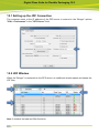
12.2
JDF WINDOW ................................................................................................................................................ 79
12.3
LOADING JDF FILES ......................................................................................................................................... 80
12.4
SORTING AND SEARCHING OF JOBS ..................................................................................................................... 81
Digital Flexo Suite for Flexible Packaging 12.0
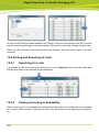
12.4.1
12.4.2
12.4.3
12.5
13
14
Searching for a Job .......................................................................................................................... 81
Sorting According to Availability ..................................................................................................... 81
Sorting According to Plate Type ...................................................................................................... 82
SENDING JDF FILES.......................................................................................................................................... 82
ADDITIONAL PROGRAMS .......................................................................................................................... 83
13.1
ACM VIEWER ................................................................................................................................................ 83
13.2
CDI MONITOR ................................................................................................................................................ 85
SUPPORT EUROPE ..................................................................................................................................... 86
Digital Flexo Suite for Flexible Packaging 12.0
1
System Requirements
The following minimum requirements must be met:
Intel Dual Core 2 processor
2 GB RAM
network board
screen resolution of 1280 x 1024 pixels
CD-ROM drive
32-bit operating system
Microsoft Windows XP
disabled firewall
disabled UAC (User Account Control)
FTP server installed and enabled
(Only in combination with Grapholas version 11 and below.)
Grapholas 7.5 on the CDI
The following configuration is recommended:
Intel 7 processor
8 GB RAM
Hard drives: 512 GB SSD
1 GB network board
Microsoft Windows 7 – 64 bit
disabled firewall and user account control (UAC)
Grapholas 12.0 on the CDI
The index and file names may not include special characters, umlauts or spaces. An
underscore "_" is the only permitted special character and can be used as a substitute
for a space.
Digital Flexo Suite for Flexible Packaging 12.0
2
Digital Flexo Suite Service
After the user login, the service for the "Digital Flexo Suite" is started automatically:
The following programs must be enabled:
gravurd
cmotsim
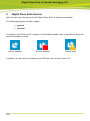
The status of the "DFS service" is shown in the Windows taskbar. Only in exceptional cases the
service is disabled or faulty:
Service enabled
Service disabled
Service faulty
In addition, an http server is installed on port 5580 as a service as of version 12.
Digital Flexo Suite for Flexible Packaging 12.0
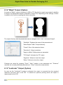
3
First Start-up of the Software
LEN and TIF files are prepared for exposure on a CDI using the "Merger". It positions the
images on the printing plate and can also rotate, mirror, crop, and invert the images as required.
Several CDIs can be controlled via the network simultaneously.
"XL-CUT" generates cutting files so that the generated plate can be cut automatically on the
Kongsberg table.
"Staggered Cut" (option) creates a user-defined cutting shape which then can be cut using "XL
CUT".
The "Viewer" is used to display and measure the LEN/TIF files. The angle and the rasterization
can also be measured.
"iMask" (option) adds an adjustable frame to the output data and creates an additional LEN or
TIF file.
"Lenticular" (option) adjusts the width of the job to adapt the data to the lens system for creating
3D images.
All important settings are copied over during an update. When the software is being installed for
the first time, the output devices must be set up and the network settings must be set.
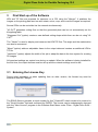
3.1 Entering the License Key
During initial installation or when updating from an older version, the license key must be
entered to start the "Merger":
The ESKO-Service provides a serial number for this "ProductID" which needs to be entered in
the "Serial Number" field and confirmed by ENTER. The license can be subsequently changed
with the "New License" program in the Windows Start Menu under "Esko - Digital Flexo Suite System".
Digital Flexo Suite for Flexible Packaging 12.0
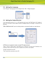
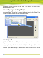
3.2 Setting the Language
In the "Merger", the language can be changed under "Edit – Change language":
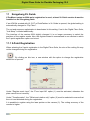
3.3 Setting the Output Devices
If no output device such as, e. g., a CDI has been set up yet, the "Edit Device List" window in
which you can define various output devices is displayed when the "Merger" is started for the
first time.
"Edit – Edit Device List" opens the dialog window to subsequently add new output devices:
A TIF license is required in order to create TIF output devices!
"New" in section "Hosts" opens a new dialog box in which you can enter the IP address or the
computer name of the CDI. Press "OK" to search for the CDI on the network.
"Accept" accepts the new CDI.
"Test" checks the connection to the CDI.
Digital Flexo Suite for Flexible Packaging 12.0
"New" in section "Other Devices" opens a new dialog box in which you can enter the name of
the TIF output device. Width and height can be set in the fields "Width" and "Height". "Negative"
inverts the background colour for the output on film. The output directory is defined in the "TIF
Target Folder" field.
"Remove" deletes the selected entry.
If an old CDI SUN computer is to be connected, you must enter the IP address "127.0.0.1". In
addition, service needs to adapt the LEN output format for the SUN.
Digital Flexo Suite for Flexible Packaging 12.0
4
Managing Data Sources
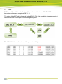
The image data can be loaded from the local hard drive, over a network release, or via FTP.
With regard to data security, transmission via FTP protocol is to be preferred over network
release.
The path entered during installation for the "User Data" is already released as a network drive.
Additional data sources can be set up under "Edit – Data Source".
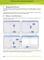
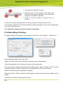
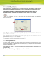
4.1 Adding a Local Data Source
Local data sources can be located on the hard drive of the computer or accessible in the
network via "share" function.
The name of the data source "Drive Name" (3) will be shown later in the "Load" dialogue.
"Disk" and "Sub Folder" (6) designate the drive letter and the directory containing the data.
Clicking "Test" (7) opens a new window with the data source set up. "Finish" (9) completes the
process. You can always switch to the previous page by pressing "Back".
Digital Flexo Suite for Flexible Packaging 12.0
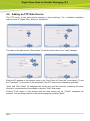
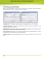
4.2 Adding an FTP Data Source
The FTP server of the data source requires a virtual directory. For a detailed installation
manual, refer to "Digital Flexo Suite 101 Installation".
The name of the data source "Drive Name" (3) will be shown later in the "Load" dialogue.
Enter the IP address or the network name in the "Host" field (6). Enter the "User-Name" (7) and
the "Password" (7) as shown in the illustration if the FTP server was installed as specified.
"Disk" and "Sub Folder" (9) designate the virtual drive and the directory containing the data.
Should no virtual directory be available, leave the "Disk" field empty.
Clicking "Test" opens a new window with the data source set up. "Finish" completes the
process. You can always switch to the previous page by pressing "Back".
Digital Flexo Suite for Flexible Packaging 12.0
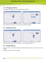
4.3 Changing an Entry
The settings of the data source can be subsequently changed.
After selecting the "Drive" (3), you can change the following settings.
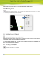
4.4 Deleting an Entry
After selecting the "Drive" (3), you can remove it by pressing "Remove" (4).
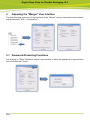
4.5 Saving Settings
Exiting via "Quit", a new window opens requesting whether you want to overwrite the current
settings.
Pressing "OK" saves the current settings.
Digital Flexo Suite for Flexible Packaging 12.0
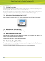
5
Adjusting the "Merger" User Interface
The user interface and some of the functions of the "Merger" can be customised and protected
with a password ("Edit – Configuration"):
5.1 Password-Protecting Functions
Left-clicking on "Enter Password" opens a new window in which the password is entered twice
and confirmed with "Close":
Digital Flexo Suite for Flexible Packaging 12.0
5.2 Changing the Password
Left-clicking on "Change Password" opens a new window in which the current password is
entered once and the new password is entered twice. "Close" confirms the input:
5.3 Entering a Password to Change Settings
Left-clicking on "Unlock" opens a new window in which the current password is entered. "Close"
confirms the input and enables the input mask:
Digital Flexo Suite for Flexible Packaging 12.0
6
Merger
The "Merger" is used to load the image data from the local hard drive or from the network and to
send it to the preselected CDI.
In addition, simple tools such as "mirror", "crop" and "rotate" are available. A description on how
to use the functions "XL CUT" and "Staggered Cut" is provided in the chapters of the same
name.
6.1 Quick Start
1
Start the "Merger" and load the required images. They are displayed in the image
gallery (on the right).
2
If necessary, select the CDI or the TIF output device. All important parameters are
updated in the "Merger".
3
Position the images on the working surface. Click on the images or the working
surface with the right mouse button to display additional information.
4
Select the required plate. Right-click on the plate to display additional information.
5
Send the job to the CDI or the TIF output device.
Digital Flexo Suite for Flexible Packaging 12.0
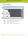
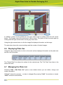
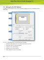
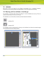
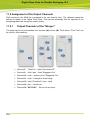
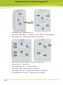
6.2 The User Interface
The Merger can be divided into four areas:
Area 1:
menu bar / toolbar with icons for the most important options
Area 2:
working surface on which the images are positioned
Area 3:
display of loaded image data
Area 4:
status bar - display of the most important settings
Digital Flexo Suite for Flexible Packaging 12.0
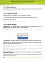
6.3 Toolbar
All important functions are listed in this area. The toolbar is subdivided into eight areas:
1
Opens a dialog box to load the image files.
2
Opens additional functions such as "Bitmap Viewer" and "Staggered Cut".
3
Activates additional functions in area 7 to adapt the output.
4
Allows to set the data output, for example, the drum, the plate, the Kongsberg
cutting file and the CDI.
5
Opens an overview of the jobs lined up on the selected CDI.
6
Opens a dialog box to send the job to the CDI or to the TIF output device.
7
Allows to modify the image data, for example, rotating and cutting.
8
Area for the various functions selected in area 3.
If some required functions are not displayed, they can be activated in the Merger configuration
settings.
Digital Flexo Suite for Flexible Packaging 12.0
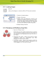
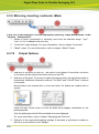
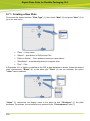
6.3.1 Loading Images
Ctrl + E
calls up a file dialog box in which the LEN or TIF files can be selected.
1 Selection of network shares.
2 Display of directories.
3 Display of files. By pressing the "Control" or the
CAPS button together with the left mouse button,
several files can be marked simultaneously; they
can then be loaded by pressing "OK". Single files
can directly be loaded by double-clicking them.
4 Multiple loading of the files.
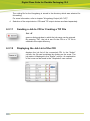
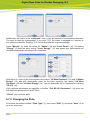
6.3.2 Displaying and Modifying Image Data
1 Opens the "Bitmap Viewer".
Several files can be marked simultaneously by pressing
the "Control"button together with the left mouse button to
view these files, each superimposed on top of the other, in
the "Viewer".
2 "Staggered Cut" (option) - Opens a new window to create
user-defined cutting lines. "PlatePatcher" and "Plato
Staggered Cut" files cannot be edited.
3 "Line Editor" (option) - Opens a new window in which the
cutting lines can be created manually. "PlatePatcher" and
"Plato Staggered Cut" files cannot be edited.
Digital Flexo Suite for Flexible Packaging 12.0
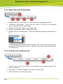
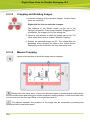
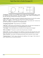
6.3.3 Plate Size and Partial Plate
1
Display of the drum circumference – This value can be changed for sleeves.
2
Switchover to partial plate – In this mode, the vacuum on the CDI is not analysed
and is reduced to a lower, safer speed.
3
Allows to set the plate width in partial plate mode.
4
Allows to set the plate height in partial plate mode.
5
Display of the list of partial plates – Plate width and plate height are selected from a
list:
The data is entered in the format 'width x height'. New values can be entered in this
format and can be added to the list. To delete an entry, select said value and press
the "Delete" key.
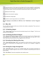
6.3.4 Frames and Cutting Lines
1
Allows to enter a frame area which is not available for the imaging process. The
area is marked red.
2
If activated, cut marks are added in the corners of each image.
3
Distance between cut marks and image.
Digital Flexo Suite for Flexible Packaging 12.0
6.3.5 Adding Text
1
Allows to activate the text function for the selected image. A frame is automatically
added to all images.
2
Allows to switch the position (top or left).
3
Allows to add an image name together with a date and time stamp.
4
Selection of the text size.
5
Input field for the text. The text should not be longer than the image width or height.
The position and width of the text is marked in yellow on the working surface.
The text can be deleted by clicking on the "X" at the end of the input field.
6.3.6 Information on Grids and Image Position
1
Allows to enter the raster count and the angle if they have not yet been included in
the image. Images without this information are marked in red on the work surface.
2
Allows to mark an image as a test wedge. For this image, the output optimisation
function is deactivated to increase productivity. If highlighted in grey, these two
fields are irrelevant for the selected CDI.
3
Allows to display and change the current image position.
4
Confirmation of the changed image position. The image is not positioned until the
changed image position is confirmed.
5
Allows to activate the overlaying option. The images can be positioned on top of
each other. Using the arrows, the selected image can be positioned above or below
another image.
6
Allows to display and change the image to make further changes.
Digital Flexo Suite for Flexible Packaging 12.0
6.3.7 "Step & Repeat" and Seamless Option for Sleeves
1
Allows to enter the number of repetitions in horizontal and vertical direction. It is
possible to set a gap between the images.
2
Displacement of the image above the zero point of the sleeve (5 activated).
3
Offset of the images to each other when horizontal repetition is selected (5
activated).
4
Predefined offset of the images to each other (5 activated).
5
Activates the seamless option. If the image is smaller than the circumference, a gap
will be automatically added and repeated in vertical direction if possible.
6.3.8 "PreMount" Output
To ensure the dimensional accuracy and the focus on the CDI for "PreMount" output, the
thickness of the glued materials must be specified.
1
thickness of the mounting film
2
thickness of the adhesive tape
3
thickness of the support such as, for example, an "airbag"
The thickness of the mounting film, of the adhesive tape and of the support can be changed by
selecting the "Premount Support" function in the "Edit" menu:
Should one entry no longer be required, select this entry and remove the value by pressing the
"Delete" key on the keyboard.
New entries are entered in the desired field using the keyboard and confirmed by pressing the
"Enter" key. The values are automatically sorted.
If the value "0" is entered in a field, this field will not be displayed in the "Merger".
Digital Flexo Suite for Flexible Packaging 12.0
6.3.9 Mirroring, Inverting, Lenticular, iMask
If this icon is not displayed, it can be displayed by selecting "Image Manipulation" under
"Options - Configuration".
1
Allows to mirror (horizontally or vertically) and invert the selected image. "ymir",
"xmir" or "inv" is added to the new files.
2
"Lenticular" output settings. For more information, refer to chapter "Lenticular".
3
"iMask" output. For more information, refer to chapter "iMask" Output.
6.3.10
Output Options
1
Selection of the drum on the CDI. This option is only shown if more than one drum
or the drum and the sleeve have been set up on the CDI.
2
Selection of the plate. To ensure an optimum imaging result, the right plate needs to
be selected. Additional information such as "UV Inline" and "Full HD Flexo" is stored
on the plate.
Normal plates are marked with a circle and Inline UV plates are marked with a
square.
Using the right mouse button to click the plate entry displays information on the
plate properties.
Only the plate types which fit the selected drum are displayed.
For more information, refer to chapter "Managing the Plate List".
3
Selection of the required Kongsberg settings. If activated, a yellow bar is visible on
the left or on the bottom in the "Merger".
Digital Flexo Suite for Flexible Packaging 12.0
The cutting file for the Kongsberg is stored in the directory which was selected for
this setting.
For more information, refer to chapter "Kongsberg Output (XL CUT)".
4
Selection of the output device. CDIs and TIF output devices are listed separately.
6.3.11
Sending a Job to CDI or Creating a TIF File
Ctrl + E
opens a dialog window in which the job name can be entered.
By pressing "OK", the job is sent to the CDI or a TIF file is
created in the output directory.
6.3.12
Displaying the Job List of the CDI
displays the job list of the connected CDI. In the "Action"
column, the job can be deleted by clicking on the cross. The
job status is displayed in the "Status" column. An explanation
of the icons can be found in the "Grapholas" user manual.
Digital Flexo Suite for Flexible Packaging 12.0
6.3.13
Cropping and Rotating Images
1 Automatic cropping of the selected images. Unused frame
areas are removed.
Right-click the icon to undo the changes.
The distance to the "Bleed" pixels can be set in the
"Merger" properties. If the image contains "Staggered Cut"
information, the image is cut on the cutting line.
2 Opens a new window in which the image can be cut. For
more information, refer to chapter "Manual Cropping".
3 Rotates the selected images by 90°. The rotated files are
generated when sending the data to the output device.
Depending on the resolution, this may take some time.
6.3.14
Manual Cropping
opens a new window in which the image can be cropped:
Starting from the frame area, a lasso can be pulled open by pressing and holding down
the left mouse button and pulling the mouse across the working surface; or the exact lasso size
can be entered in the four input fields on the right-hand side (1).
The distance between two positions in the image can be measured by pressing and
holding the left mouse button down.
Digital Flexo Suite for Flexible Packaging 12.0
Individual sections of the image can be enlarged with a square magnifier by pressing and
holding down the left mouse button and pulling the mouse across the section of interest. The
magnified image section can then be positioned using the arrow keys on the keyboard.
displays the entire image.
performs the automatic cropping.
sets back all cutting edges.
saves the current image section as a new LEN file.
Manual cropping is not available for LEN files of the "PlatePatcher" and the "Staggered
Cut".
6.4 Menu Bar
Only the additional functions which are not listed in the toolbar are described. The menu bar is
situated above the toolbar.
6.4.1 Unloading Images
"File - Unload Image" (Ctrl + u) removes the selected image from the "Merger". The file is not
deleted from the hard drive.
6.4.2 Unloading Positioned Images
"File - Remove All Positioned Images" (Ctrl + d) removes all images from the "Merger" which
are positioned on the working surface. The files are not deleted from the hard drive. This is
useful when the job was sent and several images are still in the queue.
6.4.3 Selecting the Working Directory
"File - Select Working Folder" (Ctrl + w) changes the working directory in which all images
are copied or moved during the loading process. This option is not available if images are
loaded.
6.4.4 Saving the Image Arrangement
"File - Save Plate" (Ctrl + s) saves the compiled images and the exposure parameters as
plate. When the compiled images are sent to the CDI, the plate is automatically saved under the
entered name.
"File - Save Plate as" saves the compilation under another name.
Digital Flexo Suite for Flexible Packaging 12.0
6.4.5 Loading the Image Arrangement
"File - Load Plate" (Ctrl + L) loads a previously saved or sent compilation with all parameters.
All currently loaded images are removed.
6.4.6 Deleting the Image Arrangement
"File - New Plate" (Ctrl + n) removes all images from the "Merger" and resets the parameters.
6.4.7 Automatic Positioning of the Images
"Position - Auto Arrange Images" (Ctrl + a) automatically positions as many loaded images
as possible on the working surface. Beforehand, images which were already positioned on the
work surface are removed. The type of positioning can be selected in the "Merger" properties.
6.4.8 Automatically Positioning New Images
"Position - Auto Arrange New Images" (Ctrl + h) automatically adds the loaded images to the
compilation on the working surface. Already positioned images are not removed.
6.4.9 Removing Images from the Working Surface
"Position - Unplace all" (Ctrl + u) removes all images from the working surface. The images
are not unloaded.
6.4.10
Displaying File Names
"Windows - Display Names" shows the file names in the images positioned on the working
surface.
6.5 Working Surface and Status Bar
The working surface shows the available area on the plate. It is not necessary to enter the
upper and lower borders as the entire working area is shown.
The loaded images are pulled from the right queue on the working surface by holding down the
left mouse button.
Digital Flexo Suite for Flexible Packaging 12.0
In addition, guides can be pulled from the grey frame area by holding down the left mouse
button. The images cannot be positioned in the red area. The guide can be removed again by
clicking with the right mouse button on the grey frame area.
Using the right mouse button to click the image file displays information on the image.
The status bar shows the current settings and the number of loaded images.
6.6 Displaying Plate Use
Using the right mouse button to click on the work surface displays information on the plate size
and the use of the plate.
The "Partial Plate" line shows the values for the marked area. The "Full Plate" line refers to the
entire work area.
6.7 Managing the Plate List
Selecting "Edit – Edit Plate List" opens a new window where you can delete, change and
create new plates.
"Cancel" aborts the process – no data is changed. By pressing "Quit", the window is closed.
"Next" shows the next window.
Digital Flexo Suite for Flexible Packaging 12.0
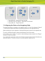
6.7.1 Creating a New Plate
First select the desired medium "Plate Type" (1), then check "New" (2) and press "Next" (3) to
go to the next menu:
"Plate" – Flexo Plates
"Sleeve" – print sleeve of DuPont and Flint
"Plate on Sleeve" – Flexo plates mounted on a print sleeve
"Steel Base" – metal backing plate for magnetic drum
"Film" – Film
If Grapholas 10.1 or higher is installed on the CDI, a plate database is shown. When the desired
plate manufacturer "Brand" (4) or the plate type "Plate" (5) are not available, the option
"other" can be selected:
"Name" (7) determines the display name in the plate list and "Thickness" (7) the plate
thickness. For sleeves, the circumference is entered in the "Circumference" field (7):
Digital Flexo Suite for Flexible Packaging 12.0
Additionally, the output in the "Distortion" field (7) can be distorted in circumference direction.
The input is made as a percentage. If you enter "5.0", the output is enlarged by 5 percent in
circumference direction. Entering "-5.0" would downsize the output accordingly.
Under "Manual" (9), enter the values for "Speed" (10) and "Laser Power" (10). The setting
"Energy" (9) sets the laser energy "Laser Energy" (10) and speed and performance are
selected automatically according to the resolution:
With Inline UV, enter for the front exposure the values "UV Main Exposure" (13) and "UV Main
Energy" (13) and with automatons, enter for the back exposure the values "UV Back
Exposure" (14) and "UV Back Energy" (14). You can deactivate the UV exposure by checking
"No UV" (12).
UV2 exposure parameters are specified in section "Full HD UV Parameters" (14) when the
CDI has been prepared for Full-HD Flexo.
"Finish" (16) saves the plate.
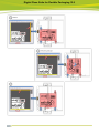
6.7.2 Changing the Plate
First select the desired medium "Plate Type" (1), then check "Edit" (2) and press "Next" (3) to
go to the next menu:
Digital Flexo Suite for Flexible Packaging 12.0
After setting the desired "Plate" (4), you can change all parameters except for the plate name.
"Next" opens the next menu.
6.7.3 Deleting the Plate
First select the desired medium "Plate Type" (1), then check "Edit" (2) and press "Next" (3) to
go to the next menu:
The desired plate "Plate" (4) is set and removed by pressing "Remove" (5).
6.8 TIF Output
"Edit – Edit Device List" opens the dialog window to subsequently add new TIF output devices
(special license required):
Digital Flexo Suite for Flexible Packaging 12.0
"New" in section "Other Devices" opens a new dialog box in which you can enter the name of
the TIF output device.
Width and height can be set in the fields "Width" and "Height".
"Negative" inverts the background colour for the output on film. The output directory is defined in
the "TIF Target Folder" field.
"Remove" deletes the selected entry.
"Expose" creates the TIF file.
6.9 Exposing Plate Borders
The "Expose frames" option can be activated in the basic settings of the "Merger" under "Edit –
Preferences…", giving the plate more stability in the washer.
The left and the right border are now shown in white. When the TIF output is negative, the
border is displayed in black.
Digital Flexo Suite for Flexible Packaging 12.0
6.10 Templates
If these functions are not displayed, they can be activated in the basic settings.
The positions, image sizes, image resolution and plate parameters are stored in the template in
order to position images quickly at a later time. This working mode is interesting for register
pinwheels such as, e.g. for Letterpress.
6.10.1
Creating a Template
To create a template, you first position the required images onto the working surface and then
select the plate type. This compilation is then saved by pressing "Template - Save Template".
6.10.2
Loading a Template
"Template - Use Template" loads the template. This is only possible when no other images are
loaded in the "Merger".
Digital Flexo Suite for Flexible Packaging 12.0
The stored positions and sizes are shown as yellow fields. After loading the images, they can be
positioned in the yellow fields.
The images must be within a certain size tolerance in order to be assigned to a field.
6.10.3
Modifying a Template
After loading the template and positioning all the images, the mask can be opened using
"Template - Edit Template". Now you can change all parameters as required and save them
using "Template - Save Template".
The modified template can now be loaded using "Template - Use Template".
6.10.4
Moving a Template
"Template - Correct Template" opens a new program in which the template can be loaded using
"File – Load Plate".
The position of single or multiple images can be changed horizontally using "Across" and
vertically using "Circumference". The value is entered absolute or relative to the current
position, ENTER is then pressed and the value is set using "Set Position".
Multiple images can be marked by pulling a square lasso around the required images with the
left mouse button pressed.
The template is saved by clicking the "Save" button.
6.11 Job Information
An HTML or XML file with the respective job name is created in the "HTM Target Folder" output
directory for each sent job.
Digital Flexo Suite for Flexible Packaging 12.0
All important information concerning the job is stored in that directory. The output directory
"d:\files\output\html" is preset.
6.12 Loading Images via "Drag & Drop"
Image files (LEN and TIF) can directly be dragged into the right image bar of the "Merger" from
the Windows Explorer. First, the data is copied into the working directory, then it is loaded. If the
"Ctrl" key is pressed at the same time, the files are always copied.
6.13 "Unique ID"
All LEN and/or TIF files from an AE12 system contain a unique code which can be read by the
Merger.
As soon as the "Unique ID" option is activated under "Options – Configuration", this code is
added to all images.
Depending on the output, the code is either inserted at the top or in the left frame area as
normal text or, for XL CUT, it is output as front text or back text.
Digital Flexo Suite for Flexible Packaging 12.0
6.14 "iMask" Output (Option)
As soon as "iMask" output is activated, a LEN or TIF file with the mask is generated in addition
to the job. An appropriate license is required to output TIFs. Depending on the settings, a frame
is added to the contour compiling the various elements.
The output directory and the parameters can be changed under "Edit – Edit Mask Output":
"Workflow": Displays the name of the parameter set.
"Mask Export Folder": Output directory.
"Frame": Size of the extension frame.
"Resolution": Output resolution.
"Apply to White": White pixels are expanded.
"Tiff Output": Activates the TIF output.
"Negative": Allows to invert the output.
"Mirror": Allows to mirror the output.
Changes are saved by pressing "Save". "New" creates a new parameter set. "Remove"
removes the currently selected parameter set. "Close" closes the setup window.
6.15 "Lenticular" Output (Option)
As soon as the "Lenticular" function is activated, the output is converted into the required
resolution and then sent to the CDI. To achieve an optimum printing result, the output is
reprocessed on the CDI.
Digital Flexo Suite for Flexible Packaging 12.0
1 Activates the "Lenticular" function.
2 Allows to enter a new resolution. This value may
differ from the original resolution of the positioned
images by a maximum of 50 DPI.
3 Allows to set the number of lenses used for
printing.
To ensure an optimum printing result, the correct number of lenses needs to be set.
The resolution results from the test print and the resulting change in the size of the image which
is set via the new resolution.
The "Lenticular" output must not be used for normal jobs.
6.16 Basic Merger Settings
The basic settings of the Merger can be changed via the menu item "Options – Preferences…":
"Units" switches between "mm" and "inch".
"Digits" and "Post colon" set the amount of numbers and/or decimal points.
"Check Images before start" checks the images of all outgoing jobs.
"File copy method" sets the behaviour while loading images. With the setting "Copy", the files
are always copied, if "Move" is selected, they are deleted from the source directory.
"Bleed" sets the border during automatic cropping.
"Expose left frame": When activated, the left border is exposed to provide more stability for the
washer.
"Show Ruler" activates or deactivates the ruler.
Digital Flexo Suite for Flexible Packaging 12.0
When restarting the "Merger", "Autoload Job" actuates automatic loading of the last job.
"Archiving Interval:" determines the number of days after which the HTML overview files and the
files of the directory "Mergelog" are archived in a ZIP file.
"JDF Server": Enter IP number or computer name of JDF server.
"Autoplace mode:" sets the method (mode) of how the images are automatically arranged on
the work surface. "Permutation", "Random", "Sorted", "MDB" and "FFDH" can be selected as
mode. MDB arranges the images which allows for easy cropping later on.
"Auto Rotate" activates the rotation of up to 7 images during automatic positioning. The
selection of these images is via the aspect ratio using "Rotate Level".
In the "Folder" window, the preset output directories can be changed.
The job information is saved in the "HTM Target Folder" directory.
Under "Plugins", the minimum size for "Microcross" and "Centerline" images can be entered.
The images are automatically enlarged to this size.
The "Merger" must be restarted after any change.
Digital Flexo Suite for Flexible Packaging 12.0
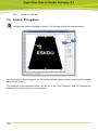
7
Kongsberg Output (XL CUT)
In order to properly process the cutting data on the Kongsberg table, at least XL Guide
version 6064 must be installed!
The Kongsberg file is generated automatically after each transmission to the CDI or each time a
TIF file is generated in the output directory. The position, the size of the images and additional
information is made available on the Kongsberg table in the form of an ACM file. Different
settings can be created and selected in order to adjust the cutting settings on the Kongsberg
table (2).
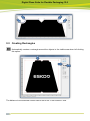
The reserved area (1) marked yellow on the left side is needed for later alignment of the plate
on the Kongsberg table. This area contains two marks and the ACM file name.
Depending on the plate thickness, an additional frame is put around each image as soon as the
45° knife is activated (3).
Once an image has been placed, you can click on the image with "shift + the right-hand mouse
button" to change the lettering.
Digital Flexo Suite for Flexible Packaging 12.0
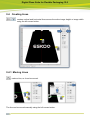
7.1 Cutting Accuracy
Using the Kongsberg table, it possible to reach a cutting accuracy of ±0.2 mm depending on the
kind of registration. The camera is more accurate than the laser.
The 3-point registration can compensate the distortion of the Flexo plates resulting from the
imaging process. This requires the Kongsberg software XL Guide 6064 (or higher).
7.2 Activating / Deactivating the XL-CUT
When "Disabled" is selected, the XL CUT output is deactivated. No ACM files will be created.
7.3 Selecting the Type of Knife
The type of knife can be defined in the XL CUT settings.
7.4 Back Labelling of the Plate
Using the pen, the plate can only be labelled on the back. For this purpose, the "Mirror X" or
"Mirror Y" option must be selected in the settings.
Cutting the back with the 45° knife is not recommended.
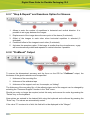
7.5 Front Labelling of the Plate
The image name (for front labelling) or the plate name (for images from the PlatePatcher) is
carved into the frame area with a knife.
This option must be activated in the settings of the XL CUT or the PlatePatcher.
Digital Flexo Suite for Flexible Packaging 12.0
7.6 Setting the XL CUT Options
Templates can be created for the XL CUT options by calling up the "XL Cut Workflow Editor…"
under "Edit":
The "XL Cut Workflow Editor" can be divided into five areas:
1
Allows to switch between XL Cut settings and channel overview.
2
Schematic view of the selected options.
3
Selection of the saved settings.
4
Options for the current selection.
5
Save, delete and create new settings.
Digital Flexo Suite for Flexible Packaging 12.0
7.6.1 Adding Settings
By selecting "New", a new window appears in which you can enter a name for this setting. "OK"
confirms the input. The new setting is automatically selected. Adjust the required settings and
save them by pressing "Save".
7.6.2 Changing Settings
Select the setting (1) and change it. Press "Save" to save the setting.
To not lose existing settings, the new settings can be renamed by pressing "Save as".
7.6.3 Deleting Settings
Select the setting (1) and delete it by pressing "Delete".
7.6.4 Possible Settings
"Register Mark": The register marks for later alignment on the Kongsberg table can be
selected from a list. An overview can be found in the appendix.
"Knife Type": Thick plates are often cut at an angle of 45°. For this purpose, select
"BevelKnife". Depending on the plate thickness, an additional frame is put around each image
except for images from the PlatePatcher (Plot / PreMount). For "PreMount", this option is
controlled automatically.
"Safe Distance": The distance between the cutting lines can be specified to avoid double cuts.
"Cut Gap": A base area that cannot be cut can be selected close to the corners to prevent
parts of the plate coming loose during cutting.
"Reserved Area": Sets the width of the reserved area in which the marks for setting up and
labelling of the plate are positioned.
"MAT Info": As an option, the name of the XL Guide "Job Setups" which will be automatically
loaded on the Kongsberg table can be entered in this field.
"4-Point Registration": This option activates the 4-point registration. In order to balance the
plate distortion, four register marks instead of two are exposed on the plate. This option
requires XL Guide 6064.
"Corner X – Corner Y": The parameters for X and Y need to be specified (see sketch) if the
edges are to be cut at an angle.
Digital Flexo Suite for Flexible Packaging 12.0
"Landscape": In order to cut, for example, a 4260" plate on an XL20 Kongsberg table, it must
be rotated by 90° before mounting it. The options "Vertical" and "Y-Mirror" are deactivated. In
this case, the yellow reserved area is always on the bottom.
"Align Vertical": This option is activated to display the reserved area on the left of the working
surface in the "Merger". If deactivated, the reserved area is shown at the bottom.
"Mirror X" / "Mirror Y": The coordinates of the cut on the X axis and/or the Y axis can be
mirrored depending on the alignment on the Kongsberg table.
"Kongsberg Target Path": Output directory of the ACM file.
"Safe Cut": If plate pieces are lifted during the cutting process, this option can be activated. As
a consequence, the processing time of the Kongsberg table will increase.
"Text Height": When labelling the back of the plate, the text height can be changed.
"Mirror Job Name": This option is used to mirror the job name on the plate.
"Front Text": This option activates the front labelling in the frame area using the knife. This
deactivates all options for back labelling. The text can be positioned at the bottom or on the left.
"Mirror Plot-Text": As an option, the labelling on the back can be output as a mirror image.
"Translate Space": The file name determines the labelling of the image. If this function is
active, underscores are converted into spaces.
Digital Flexo Suite for Flexible Packaging 12.0
"Text Orientation": Three positions on the left and lower side can be used to label the image.
On the back, the text can be set to "Center".
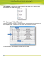
7.7 Overview of Output Channels
"Channels" provides an overview of the output channels. All displayed channels must be set up
on the Kongsberg table. By pressing the "Print" button, the overview can be printed.
For more information, refer to chapter "Kongsberg XL Guide 6064".
Digital Flexo Suite for Flexible Packaging 12.0
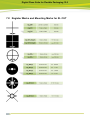
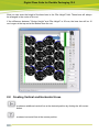
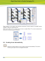
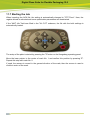
7.8 Register Marks and Mounting Marks for XL CUT
Digital Flexo Suite for Flexible Packaging 12.0
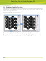
7.9 Recommended Settings in XL CUT
The plate can be set up on the Kongsberg table more easily with vertically arranged
positional markers "Align Vertical".
For small plate pieces, a "Cut Gap" of 0.5 mm is recommended so that the plate pieces
are not triggered automatically.
The marks "reg_502_c" 1nd "reg_503_c" are suited for positioning using the laser
pointer on the Kongsberg table.
Digital Flexo Suite for Flexible Packaging 12.0
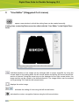
8
"Staggered Cut" (Option)
opens a new window in which the cutting line can be created.
Cutting lines created by Plato cannot be edited with "Staggered Cut" in the Digital Flexo
Suite.
8.1 Toolbar
The toolbar is always located on the right-hand side. Only available functions are activated.
Digital Flexo Suite for Flexible Packaging 12.0
Individual sections of the image can be enlarged with a square magnifier by using the
mouse wheel or by holding down the left mouse button and pulling the mouse across the
section of interest. The magnified image section can then be positioned using the arrow
keys on the keyboard. The image section can be zoomed out by pressing "Ctrl" and the
left mouse button.
displays the entire image.
opens the "Digital Video Drill" module if the respective license is available. For a
detailed operating manual of this module, refer to document "Digital Flexo Suite Tools".
activates or deactivates the split screen which displays the upper and the lower cutting
line simultaneously.
moves a point. By pressing this button and the "Ctrl" button, the distance to the original
position is displayed in addition.
moves the upper line. For this purpose, a point is moved with the left mouse button. By
pressing this button and the "Ctrl" button, the distance to the original position is displayed
in addition.
adds a point.
deletes a point.
marks the points in an area. These can then be deleted by pressing the "DEL" button.
centres the points vertically between two objects.
centres the points horizontally between two objects.
adapts the points to the upper object contour.
The distance between two positions in the image can be measured by pressing and
holding the left mouse button down.
corrects excessively acute angles so that the plate will not crack in these areas.
Digital Flexo Suite for Flexible Packaging 12.0
cuts the margins. This function is only available if the entire image is displayed.
changes the margins. This function is only available if margins were automatically
created beforehand.
creates an additional vertical line at the desired position by clicking the left mouse button.
creates an additional horizontal line at the desired position by clicking the left mouse
button.
detects the desired position for the vertical cutting line automatically. The section
containing the object must be enlarged beforehand.
detects the bear bars automatically. This function is only available if the section with the
bear bars was enlarged.
loads a saved cut.
saves the current cut.
indicates that a new cutting line must be created.
deletes the cutting line.
"Design Height" sets the distance between the upper and the lower cutting line.
"Bar Height" sets the height of the bear bars. This function is only available if bear bars were
detected.
"Shrink" reduces the lower line for a gapless mounting of the plates.
"Sample Step" and "Line Distance" are available if the adaptation to the object contour is
selected. With these functions, the distance between the points and the distance to the object
contour is set.
"Apply To Job" applies the cut contour to the entire job. For this purpose, the cut contours
must be loaded in the "Merger".
"OK" applies the cut contour.
"Cancel" cancels the editing process.
Digital Flexo Suite for Flexible Packaging 12.0
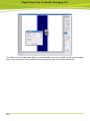
8.2 Creating a New Cutting Line
If the file contains no cutting information, the starting point on the left side of the image must be
determined by clicking the left mouse button, then the cutting lines must be added one after
another with the left mouse button.
Angles larger than 90° cannot be entered.
The contour can only be further edited when the line was created for the entire width.
The distance to the lower cutting lines can be set in the "Design Height" field.
Digital Flexo Suite for Flexible Packaging 12.0
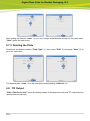
8.3 Centring Points
centres the points horizontally between two objects. A frame can be pulled
around the relevant points using the left mouse button (hold pressed and pull). If
there is no graphic object on one side (top or bottom), the frame is used as
border:
Digital Flexo Suite for Flexible Packaging 12.0
centres the points vertically between two objects.
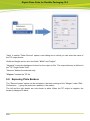
8.4 Applying the Cutting Line to the Entire Job
After creating the cutting line, the "Apply To Job" button can be used to automatically transfer
the cutting line to the entire job. To this end, the other separations must already have been
loaded into the "Merger":
Digital Flexo Suite for Flexible Packaging 12.0
8.5 Adapting Points to the Object Contour
adapts the points to the upper object contour. To this end, a frame is drawn
around the desired area by pressing and holding the left mouse button down. The
distance between the points can be set using "Sample Step", and the distance to
the object contour can be set using "Line Distance". If negative values are
entered, the cutting line will be drawn in the design.
Digital Flexo Suite for Flexible Packaging 12.0
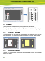
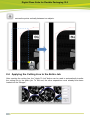
8.6 Cutting Margins
cuts the margins. This function is only available if the entire image is displayed
and no bear bars have been defined yet.
The red
areas on the right and left of the image show the unused space. The cutting line is automatically
moved to the lateral margins of the image.
changes the margins. This function can also be called up by right-clicking the red
area. A new window is opened in which you can enter the "Left Gap" and the "Right Gap" of the
margins.
Digital Flexo Suite for Flexible Packaging 12.0
"OK" applies changes.
"Reset" removes the frame.
"Cancel" cancels this change.
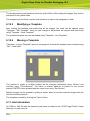
8.7 Detecting the Bear Bars Automatically
detects the bear bars automatically. This function is only available if no margins
have been defined yet and an area was enlarged.
1
Enlarge the bear bars until no other elements are visible.
2
By left-clicking on the icon for automatic detection, the image section is analysed
and the detected area is displayed in green.
3
By right-clicking on the green area, a new window is opened in which the width of
the bear bar can be changed asymmetrically. The last changed values will be
applied automatically.
"Left Outer Border"
"Left Inner Border"
left bear bar - left margin
left bear bar - right margin
"Right Inner Border"
"Right Outer Border"
right bear bar - left margin
right bear bar - right margin
Repeat this step for the second bear bar.
Digital Flexo Suite for Flexible Packaging 12.0
Now you can enter the height of the bear bars in the "Bar Height" field. These bars will always
be arranged in the centre of the cut.
If the difference between "Design Height" and "Bar Height" is 20 mm, the bear bar will be 10
mm longer at the top and at the bottom than the cut.
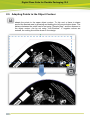
8.8 Creating Vertical and Horizontal Lines
creates an additional vertical line at the desired position by clicking the left mouse
button.
creates a horizontal line at the mouse position.
Digital Flexo Suite for Flexible Packaging 12.0
Right-clicking on a line opens a new window in which the "Position" and the "Line Width" can be
changed. "Remove" removes the line.
When a line width of "0" is entered, only one line is created. When "2" or more is entered, two
lines will be inserted having this distance.
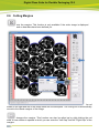
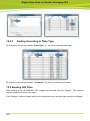
8.9 Creating Lines Automatically
detects the desired position for the vertical cutting line automatically. The section
containing the object must be enlarged beforehand.
Digital Flexo Suite for Flexible Packaging 12.0
The width of the first detected object is automatically used as line width for all vertical cutting
lines. If not requested, the line width can be changed by right-clicking the vertical line.
Digital Flexo Suite for Flexible Packaging 12.0
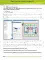
9
"Line Editor" (Staggered Cut License)
opens a new window in which the cutting lines can be created manually.
Cutting lines created by Plato cannot be edited with the "Line Editor" in the Digital Flexo
Suite.
Individual sections of the image can be enlarged with a square magnifier by using the
mouse wheel or by holding down the left mouse button and pulling the mouse across the
section of interest. Using the arrow keys on the keyboard or the right mouse button, the
image section can be moved in the desired direction. The image section can be zoomed
out by pressing "Ctrl" and the left mouse button.
displays the entire image.
activates the setting of lines using the left mouse button.
activates the contour recognition feature using the left mouse button.
Digital Flexo Suite for Flexible Packaging 12.0
automatically creates a rectangle around the objects in the visible area.
marks a line, so it can be deleted.
marks a line, so it can be moved.
marks several objects, so they can be deleted.
loads a stored template.
saves the information in a template.
The distance between two positions in the image can be measured by pressing and
holding the left mouse button down.
deletes the information.
9.1 Using Masks
The software does not recognise halftone screen areas as a contour. To write the
corresponding cut contour into a file with halftone screen areas, a file with a solid area is
required for each job or ink. The file with a solid area is loaded and edited using the "Line
Editor".
When pressing "OK", the information is additionally written into the desired file with the halftone
screen areas provided that "FREECUT" is used in the file name as follows.
9.1.1 Applying a Mask to the Entire Job:
Mask:
job name_FREECUT.len
Ink 1:
job name_ink1.len
Ink 2:
job name_ink2.len
9.1.2 Applying a Mask to One Ink Only:
Mask 1: job name_Ink1_FREECUT.len
Ink 1:
job name_ink1.len
Mask 2: job name_Ink2_FREECUT.len
Digital Flexo Suite for Flexible Packaging 12.0
Ink 2:
job name_ink2.len
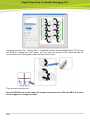
9.2 Contour Recognition
activates the contour recognition feature. Left-clicking selects the desired contour.
The first black-to-white change to the left of the selected mouse position is used as the starting
point for the contour.
The distance to the selected contour can be set in the "Line Distance" field. To maintain this
distance, the corners receive a round contour:
Digital Flexo Suite for Flexible Packaging 12.0
9.3 Creating Rectangles
Automatically creates a rectangle around the objects in the visible area when left-clicking
this option:
The distance to the selected contour can be set in the "Line Distance" field.
Digital Flexo Suite for Flexible Packaging 12.0
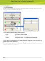
9.4 Creating Lines
creates vertical and horizontal lines across the entire image height or image width
using the left mouse button.
9.4.1 Moving Lines
marks a line, so it can be moved.
The line can be moved manually using the left mouse button.
Digital Flexo Suite for Flexible Packaging 12.0
Right-clicking opens a new window in which the new position can be entered.
9.4.2 Deleting Lines
activates the marking function. You can mark a line with the left mouse button and delete
it using the "Delete" key on the keyboard.
9.5 Deleting Several Objects
marks several objects, so they can be deleted.
By pressing and holding the left mouse button, a rectangle is pulled across the desired objects.
Then use the "Delete" key on the keyboard to delete them.
You cannot delete individual lines from the contour recognition and from the rectangles. The
whole object is selected when marking it.
9.6 Creating a Template
saves the information in a template.
Digital Flexo Suite for Flexible Packaging 12.0
9.7 Loading a Template
loads a previously saved template. In case the dimensions of the image are correct, the
information is applied to the loaded job.
9.8 Loading an Image
The menu item "File – Load Image" shows the "Load" dialogue:
9.9 Save Information
After all lines have been set, the information is written into the LEN files with "OK".
9.10 Export Finished Files
When the "Export" option is activated, the job is copied or moved automatically to the output
folder.
In the "File – Edit" menu under "Export Folder", the path of the output directory is specified
where the files are copied to.
Using the "Move" option, you can move the files into the output folder.
Digital Flexo Suite for Flexible Packaging 12.0
10
Hotfolder
LEN and TIF files are loaded into the Merger automatically from a predefined directory.
Positioning on the working surface and transmission to the CDI is performed manually.
10.1 Working with the Hotfolder in the Merger
The Hotfolder is activated after starting the "Merger" if active Hotfolders were set up. Files are
loaded automatically and lined up on the right.
The Hotfolder icon in the toolbar activates and deactivates the Hotfolder:
Hotfolder ON
Hotfolder OFF
The Hotfolder must be deactivated by clicking on the Hotfolder icon before the loaded images
can be positioned on the working surface:
Digital Flexo Suite for Flexible Packaging 12.0
10.2 Setting up the Hotfolder
Before using the Hotfolder for the first time, it has to be set up using the "Hotfolder" program
(Windows Start Menu - Esko – Digital Flexo Suite - System):
"Identification": The Hotfolder name specified here is displayed later on in the "Merger".
"Hotfolder directory": A directory, from which the LEN or TIF files are loaded, has to be
selected using the "Browse" button.
"Working Dir": All the files are copied from the Hotfolder automatically into a working directory
which has to be selected here using the "Browse" button.
"Result Directory": Optionally, you can define a subdirectory in the working directory. The files
transmitted to the CDI are then saved in this subdirectory.
"Input File Type": With "Grapholas Image" you can choose only LEN, only TIF or both file
types.
Digital Flexo Suite for Flexible Packaging 12.0
11
Kongsberg XL Guide
If PreMount output or 6064-point registration is used, at least XL Guide version 4 must be
installed on the Kongsberg table.
If an ACM file created with XL CUT or PlatePatcher in XL Guide is opened, the global setting is
automatically changed to "Ctp Flexo".
The cut and sequence optimization is deactivated in this setting. If set in the Digital Flexo Suite,
"Job Setup" is loaded additionally.
The interface of the version 6064 slightly changed. It is no longer necessary to select the
positions of the register marks. Also, the register wizard is summarised in one window in which
the 3-point registration option can be set.
11.1 2-Point Registration
When selecting the 2-point registration in the Digital Flexo Suite, the size of the cutting file may
not be changed during the registration.
By clicking on this icon, a new window with the option to change the registration
behaviour is opened:
Under "Register mark input", the "From input file" option (1) must be activated, otherwise the
plate cannot be cut correctly.
Under "Transformation", the "Offset and rotation only" option (2) must be selected to ensure that
the cut is not distorted during the registration.
It is possible to register using the laser pointer or the camera (3). The cutting accuracy of the
camera is higher.
Digital Flexo Suite for Flexible Packaging 12.0
11.2 4-Point Registration
When selecting the 4-point registration in the Digital Flexo Suite, the cutting file can be distorted
differently in horizontal and vertical direction in order to compensate the distortion of the plate.
A current ACM file must be loaded from the Digital Flexo Suite before setting the
registration options. Otherwise the "Different X/Y scale" option is not available.
By clicking on this icon, a new window with the option to change the registration
behaviour is opened:
Under "Register mark input", the "From input file" option (1) must be activated, otherwise the
plate cannot be cut correctly.
Under "Transformation", the "Different X/Y scale" option (2) must be selected in order to
differently distort the cut in X and Y direction.
The registration should be performed with the camera (3).
11.3 Setting the Tools
The knives can be set in the "Job Setup" window which is opened via the "Options" menu. Each
element in the ACM file is assigned to its own channel (line) (1). The speed and the acceleration
(3) must be determined on site.
Since Digital Flexo Suite 7.5, the ACM file contains more channels which can be selected at the
Kongsberg table.
Therefore, the "No tool = Ignore" (2) option must be activated.
Digital Flexo Suite for Flexible Packaging 12.0
11.3.1
"Front Text" Labelling
For the "Front Text" labelling, a knife must be set up on channel 12. In order to crave the text
only into the surface, the "Depth Unit" (4) is set to "MM" and the cutting depth of the knife is
reduced (5). The exact value for "T" must be determined on site. An initial value of -0.7 mm (5)
may be used. This value must be entered in both fields.
11.3.1
Setting the Knife for "Staggered Cut"
The angle for the lifting of the knife has to be set to 14° to achieve the ideal speed when cutting
the "Staggered Cut" contour. Go to "Job setup" under "Extended setup …" where you will find
the field "Lift angle" in which the desired angle of 14° can be entered.
11.3.2
Setting the "Bevel Knife" (45° Knife)
Before using the "BevelKnife" (45° knife), the option "Single cut" must be activated in "Job
Setup" under "Extended Setup …" as the step will otherwise not be performed properly. The
knife speed for the "BevelKnife" should not exceed a value of "30".
Digital Flexo Suite for Flexible Packaging 12.0
11.3.3
Drill Setup
In order for the drill to drill - independent of the plate thickness - to the table top, the drilling
depth must be limited by entering "T" (1). The speed should be set to "1000" (2).
11.4 Optimisation
To use the cutting lines at best, the "Sequencing" option should be activated in the XL Guide
settings:
Digital Flexo Suite for Flexible Packaging 12.0
11.5 Assignment of the Output Channels
Each element in the ACM file is assigned to its own channel (line). The channels cannot be
defined or hidden in the Digital Flexo Suite. This has the advantage that the operator of the
Kongsberg table can change the output quickly.
11.5.1
Output Channels of the "Merger"
The plate may be cut and labelled from the front (A) or back (B). The function "Front Text" can
be used for front labelling.
Channel 5:
"Kiss Cut" – label "Permanent ID"
Channel 9:
knife / pen – lines "Staggered Cut"
Channel 10: knife – contour cut of "Staggered Cut"
Channel 11: knife - cutting line of the image
Channel 12: knife ("Fronttext") / pen – label
Channel 14: pen – centerlines
Channel 32: "NO TOOL" – Do not set any tools.
Digital Flexo Suite for Flexible Packaging 12.0
Channel 13: drill – PlatePatcher "Drill"
Channel 17: "Bevel Knife" – 2. finishing cut at "PreMount" unexposed plate
Channel 23: knife – PlatePatcher register marks and text
Channel 6: "Kiss Cut" and pen – shortened "Center lines"
Channel 7: pen – "Center lines"
Channel 18: knife / pen – lines ("Line Editor")
Channel 19: knife – object contour ("Line Editor")
Channel 21: knife / pen – rectangle around object ("Line Editor")
Channel 22: knife / "No Tool" – image border ("Line Editor")
Digital Flexo Suite for Flexible Packaging 12.0
Channel 8: knife – "Microcross" from front side
Channel 8: "Kiss Cut" and pen – "Microcross" from the back
Channel 20: drill – "Digital Video Drill"
11.6 Aligning the Plate on the Kongsberg Table
The positioning marks are normally on the operator’s side (1+2). Only if the alignment "Vertical"
+ "Landscape" has been deactivated, the positioning marks are on the right-hand side (3).
When activating the 3-point registration, a third positioning mark is placed on the opposite side.
The text for identifying the plate is always located between the first two marks.
If the "X-Mirror" (X) or "Y-Mirror" (Y) option for back labelling has been selected in the "Merger",
the plate is rotated accordingly.
As cut optimisation cannot be used for the 45° Knife, the plate should be fixed to the table as an
additional measure. To achieve a clean cut, this knife requires a special set-up.
Digital Flexo Suite for Flexible Packaging 12.0
Digital Flexo Suite for Flexible Packaging 12.0
11.7 Starting the Job
When importing the ACM file, the setting is automatically changed to "CTP Flexo". Here, the
register wizard is activated and some optimisation parameters are deactivated.
If the "MAT Info" field was filled in the "XL CUT" submenu, the file with the knife settings is
automatically loaded.
The setup of the plate is started by pressing the "I" button on the Kongsberg operating panel.
Move the laser pointer to the centre of mark No. 1 and confirm this position by pressing "I".
Repeat this step with mark No. 2.
If used, the camera is moved in the general direction of the mark, then the mouse is used to
click the centre of the mark.
Digital Flexo Suite for Flexible Packaging 12.0
12
JDF
DFS Server 1.0 and Automation Engine 10.1 must be installed to use JDF. The DFS Server can
be located on the same computer as AE 10.1.
The status of the JDF jobs is displayed in the AE 10.1 Pilot. It is possible to integrate important
data such as plate consumption in an existing MIS system.
The AE10.1 Pilot shows the status and the parameter of the job:
Digital Flexo Suite for Flexible Packaging 12.0
12.1 Setting up the JDF Connection
The computer name or the IP address of the DFS server is entered in the "Merger" options
"Edit – Preferences" in the "DFS Server" field.
12.2 JDF Window
When the "Merger" is connected to the DFS server, an additional window opens and shows the
JDF files:
Area 1 contains the load and filter functions:
Digital Flexo Suite for Flexible Packaging 12.0
Loads the marked job.
Loads all jobs that have same resolution and plate type as the
marked job.
Filters the job list according to entered text.
Resets all filters.
Shows only jobs which correspond to the selected plate type in the
"Merger" (display is green).
In Area 2, the job list can be sorted by "Job Name", "Plate Type" or resolution "DPI".
Area 3 shows the job with the according "Status":
The job can be loaded. The plate type complies with the plate type
that is currently set.
The plate type of the job does not comply with the plate type
currently set.
The plate type of the job cannot be found in the plate list.
The icon "+" in front of each job shows all colours/statuses of the respective job. The icon "-"
removes the colour display.
12.3 Loading JDF Files
To load a file, double-click the according job or colour. You can mark and load several files by
using the "Ctrl" button together with the left mouse button.
If the plate type is set to "other", all JDF images are available. Otherwise, only those JDF
images are available which correspond to the plate that is currently set:
Digital Flexo Suite for Flexible Packaging 12.0
As soon as the files have been loaded to the "Merger", they are removed from the JDF overview
and the according plate type is set automatically. Now you can no longer change the plate type.
When the JDF files have been removed from the "Merger", they are shown again in the JDF
overview.
12.4 Sorting and Searching of Jobs
12.4.1
Searching for a Job
It is possible to filter the overview by entering text in the "Jobname" field. Only jobs which start
with the first letters of the entered text are displayed:
12.4.2
Sorting According to Availability
When a plate type (1) has already been selected and the plate is to be filled with more images,
the overview can be sorted in that way (2) that it only shows jobs for the plate type currently set
(3):
Digital Flexo Suite for Flexible Packaging 12.0
12.4.3
Sorting According to Plate Type
By clicking on the column header "Plate Type" (1), the list is sorted by plate type:
By clicking on the column header "Job Name" (2), the list is sorted by job name.
12.5 Sending JDF Files
After sending a job, all positioned JDF images are removed from the "Merger". This ensures
that the images will not be sent again.
If the "Merger" contains images which are not positioned yet, the plate type cannot be changed.
Digital Flexo Suite for Flexible Packaging 12.0
13
Additional Programs
With Digital Flexo Suite, two additional programs are installed which can be found under
"Esko – Digital Flexo Suite – System":
13.1 ACM Viewer
This program is used to display and control the ACM files which were created by using the
Digital Flexo Suite.
After the Digital Flexo Suite installation, all ACM files are automatically linked to the "ACM
Viewer".
The distance between two points can be measured by using the right mouse button (hold
pressed) (1). The image content can be enlarged by using the mouse wheel (2) and moved by
using the left mouse button (hold pressed and pull) (3).
Double-click one ACM file and an additional window (4) will be opened. "Start" in the "Manual
Step" area (5) starts a simulation of the cutting and drawing process. In the "Settings" area (6),
the line thickness can be changed.
Additional information can be displayed in the "View" menu.
If the ACM Viewer of the Digital Flexo Suite is used, LEN files can also be displayed.
Cutting information of "Staggered Cut" and CAD information of Flexrip are displayed in addition.
Digital Flexo Suite for Flexible Packaging 12.0
Using the function "File – Overlay File", it is possible to place the according LEN or TIF file over
the ACM file. Holding the "Ctrl" button, you can move the contour of the ACM with the left
mouse button until both register marks are above each other.
Then you can check the cut.
Several LEN files are created when the output is performed on a CDI with ABS. A revision
of the images is no longer possible!
Digital Flexo Suite for Flexible Packaging 12.0
13.2 CDI Monitor
The CDI monitor displays the current job, the status and the remaining time for the current
imaging processes of the CDIs in the network:
The CDI status is displayed with the following colours:
grey:
CDI or service is not activated
red:
CDI is activated and waits for jobs
green:
CDI exposes a plate – The remaining time is displayed.
The CDI list of the Digital Flexo Suite is used automatically. Right-click on the CDI monitor to
change CDI list under "Preferences".
"Fullscreen" displays the monitor as full screen. "Widget" removes borders and the monitor will
always be displayed in the foreground.
Digital Flexo Suite for Flexible Packaging 12.0
14
Support Europe
To contact ESKO, please visit www.esko.com.