1
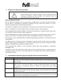
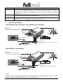
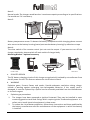
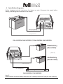
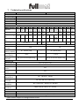
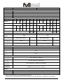
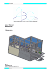
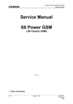
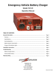
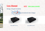
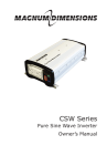
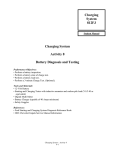
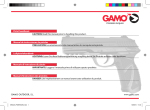
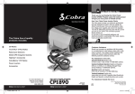
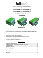
FUM-1215CBPH / FUM-2407CBPH
FUM-1230CBPH / FUM-2415CBPH
FUM-1260CBPH / FUM-2430CBPH
Multistage battery charger
User manual
Design Features
•
PFC function (except FUM-1215CBPH and FUM-2407CBPH).
•
Sleeping mode function.
•
Wide input voltage (universal) range operation (except FUM-1215CBPH and FUM-2407CBPH).
•
LCD remote control.
•
Battery temperature sensor function.
•
Tri-LED color indicator for different charge stage.
•
Adjustable charging mode switch for different lead-acid battery types.
•
Prevent the battery overcharging, and extend the battery life.
•
For recovery of the aging (sulfated) battery.
List of contents
1.
2.
3.
4.
5.
6.
7.
8.
9.
Important safety instructions ...................................................................................... 1
Installation location; physical requirements for installation ....................................... 1
Charger overview......................................................................................................... 2
Installation diagrams. .................................................................................................. 4
Charging voltage graph ................................................................................................ 5
Charger LCD remote control ........................................................................................ 6
Technical specifications ............................................................................................... 7
Charging and discharging formulae ............................................................................. 10
Warranty...................................................................................................................... 11
1. Important safety instructions
WARNING
Before installing and using the charger, read all instructions and
cautionary marking on the charger, the batteries and all
appropriate sections of this guide.
General safety precautions
Do not expose the charger to rain, snow, spray, or bilge water. To reduce risk of fire hazards,
do not cover or obstruct the ventilation openings. Do not install the inverter in a zeroclearance compartment. Overheating may result.
The charger is designed to be permanently connected to your AC and DC electrical systems.
Never use chagers at a location where there is a danger of gas or dust explosions.
Use only attachments recommended or sold by the manufacturer. Doing otherwise may result
in a risk of fire, electric shock or injury to persons.
Do not disassemble the charger. Attempting to service the unit yourself may result in a risk of
electric shcok of fire. Internal capacitors remain charged after all power is disconnected.
The charger must be provided with an equipment-grounding conductor connected to the AC
input groung.
To reduce the risk of electrical shock, disconnect both AC and DC power from the charger
before attempting any maintenance or cleaning or working on any circuits connected to the
charger. Turning off controls will not reduce this risk.
Do not operate the charger if it has received a sharp blow, been dropped, or otherwise
damaged in any.
To avoid a risk of fire and electric shock make sure that existing wiring is in good electrical
conditions and the wire size is not undersized. Do not operate the inverter with damage or
substandard wiring.
2. Installation location; physical requirements for installation
Condition
Clean
Cool
Dry
Safe
User’s manual
Description
Do not expose the charger to metal filings or any other form of conductive
contamination. The presence of conductive contamination can cause damage and void
your warranty.
For best performance, the ambient air temperature should be between -15°C (5°F) and
45°C (113°F) – the cooler the better. At higher ambient temperatures, the output
current will be automatically reduced to protect the charger from high internal
temperatures.
The unit is intended for use in a dry location. Do not allow water or other fluids to drip
or splash on the charger. Do not mount the charger in an area subject to rain, spray or
splashing bilge water.
This battery charger is Ignition Protected, so it can be installed in areas containing
gasoline tanks or fittings which usually require Ignition Protected equipment. It is safest
not to install electrical equipment in these areas.
-1-
FUM-12xxCBPH/24xxCBPH
Condition
Ventilated
Description
Allow at least 10 cm (4 inches) of clearance around all sides of the charger for air flow.
Ensure that the ventilation openings on the unit are not obstructed. If mounting in a
compartment, ventilate the compartment with louvres or cut-outs to prevent
overheating.
Close to AC
junction box
Close to
batteries
Avoid the use of extended wire lengths if possible.
Avoid excessive cable lengths and use the recommended wire lengths and sizes.
Undersized or overly long cables may affect charging accuracy.
3. Inverter operation
FUM-1215CBPH; FUM-2407CBPH // FUM-1230CBPH; FUM-2415CBPH
Warning :
Don't reverse the (+) and (-) of the
battery! Or internal damage will result!
DC OUTPUT
-Black
+Red
Main Switch
Fault
Slave Switch ( Note 4 )
Mode
AC Input
Fan
Sleeping Mode
Normal Mode
( Note 1 / Note 2 )
ON / OFF
Charging Status
Remote control-LCD
Charging Mode Selection (Please refer to page 5)
Battery Temp. Sensor ( Note 3 )
FUM-1260CBPH; FUM-2430CBPH
Warning :
Don't reverse the (+) and (-) of the
battery! Or internal damage will result!
DC OUTPUT
+Red
Fault
(Main)
Slave Switch ( Note
Mode
Main Switch
(2nd)
-Black
AC Input
Fan
4)
Sleeping Mode
Normal Mode
( Note 1 / Note 2 )
ON / OFF
Charging Status
Remote control-LCD
Charging Mode Selection (Please refer to page 8)
Battery Temp. Sensor ( Note 3 )
Note 1:
Sleeping mode: Fan would stop and the charger working sound would be smaller, so the
output current would be 5A (12V spec.) or 2.5A (24V spec.)
User’s manual
-2-
FUM-12xxCBPH/24xxCBPH
Note 2:
Normal mode: The charger would work as it maximum capacity according to its specifications.
Fan would run if it is necessary.
Note 3:
Warning : Don't reverse the (+) and (-) of the battery!
Or internal damage will result!
※Note 3
ry
tte
Ba
red
black
Battery temperature sensor: To detect the battery temperature while charging please connect
wire sensor to the battery housing (metal part touches battery housing) by adhesive or tape.
Note 4:
The slave switch of the remote control just cuts out the output. If you want to turn off the
charger completely, please switch off main switch of charger body.
Mounting Bracket – optional accessory
Wall
FRONT VIEW
a.
SIDE VIEW
TOP VIEW
SIDE VIEW
ISOLATED DESIGN
The DC battery charging circuits of this charger are galvanically isolated by a transformer from
the AC power circuits. This feature reduces the risk of electric shock.
b.
WARNING
Explosive gases; Prevent flames and sparks; Provide adequate ventilation during charge.
Include a warning against recharging non-rechargeable batteries. If the supply cord is
damaged, it must be replaced by a special cord or assembly available from the manufacturer
or its service agent.
c.
Explosive gas precautions
1.
2.
The charger have been approved as Ignition Protected. They may be installed in areas
containing gasoline tanks and fittings which require Ignition Protected equipment. It is
safest not to install electrical equipment in these areas.
To reduce the risk of battery explosion, follow these instructions and those published by
the battery manufacturer and the manufacturer of the equipment in which the battery
is installed.
User’s manual
-3-
FUM-12xxCBPH/24xxCBPH
4. Installation diagrams.
Before charging, read the instructions; for indoor use only. Disconnect the supply before
making or breaking the connection to the battery.
Warning : Don't reverse the (+) and (-) of the battery!
Or internal damage will result!
ry
tte
Ba
black (negative)
red (positive)
FUM-1215CBPH; FUM-2407CBPH // FUM-1230CBPH; FUM-2415CBPH
ry
tte
Ba
Main battery
(the red Cable)
Warning : Don't reverse the (+) and (-) of the battery!
Or internal damage will result!
( Note 5 )
red (positive)
ery
tt
Ba
2nd battery
(the red terminal)
red (positive)
black (negative)
DC Negative Bus
FUM-1260CBPH; FUM-2430CBPH
Note 5:
nd
Please connect the main battery cable prior to 2 battery ternminal if you just have 1 battery.
User’s manual
-4-
FUM-12xxCBPH/24xxCBPH
5. Charging voltage graph
ON
Mode 1
(100)
Suitable for recharging lead
storage battery
Mode 2
(120)
Suitable for recharging gel
storage battery
Mode 3
(003)
Mode 6
(123)
Suitable for recharging lead
storage battery, which is in good
condition (no sulfated situation)
and completely disconnected
from the devices it runs,
because this mode has the
additional stage, the battery
may reach voltage too high for
them. And the limited current
delivered by the battery charger.
This is not able to provide power
for devices, and simultaneously
charge the battery.
Suitable for recovery sulfated gel
battery, i.e. diacharged batteries
unused for long periods or the
battery that never recharges
completely. This mode should be
applied with the battery
completely disconnected from
the devices it runs.
Suitable for recovery sulfated
lead storage battery, i.e.
diacharged batteries unused for
long periods or the battery that
never recharges completely. This
mode should be applied with the
battery completely disconnected
from the devices it runs.
DC power supply 12.2V (for 12V
spec.) / 24.5V (for 24V spec)
Mode 7
(000)
DC power supply 13.5V (for 12V
spec.) / 27V (for 24V spec)
1 2 3
ON
standby
orange
red
orange
LED color
green
standby
orange
red
orange
LED color
green
1 2 3
ON
1 2 3
ON
Mode 4
(020)
1 2 3
ON
Mode 5
(023)
1 2 3
ON
standby
orange
standby
red
red
orange
LED color
red
LED color
green
green
1 2 3
1
ON
1 2 3
User’s manual
-5-
standby
green
green
LED color
FUM-12xxCBPH/24xxCBPH
6. Charger LCD remote control
fault indicator
Fault
Fault
Mode
Mode
ON / OFF
ON / OFF
2. Mode 1 ~ 5, no battery connected.
1. OFF
battery volt
Fault
Mode
Fault
Mode
ON / OFF
battery capacity
ON / OFF
ON/OFF switch
charging mode
charging current
3. Mode 1 ~ 5 while charging.
4. Mode 1~ 5, float stage display.
power supply DC output volt
fault indicator (red lighting)
Fault
Mode
Fault
Mode
ON / OFF
output current
ON / OFF
ON/OFF switch
5. Mode 6 ~ 7: power supply mode.
6. Over temperature protection.
fault indicator (red lighting)
Fault
Mode
ON / OFF
7. High battery volt protection.
User’s manual
-6-
FUM-12xxCBPH/24xxCBPH
7. Technical specifications
Model
INPUT
Voltage range
Frequency range
Efficiency
Power factor
Input socket
OUTPUT
Mode selection M1
14.7V
Standby
1A
Bulk stage
Absortion stage
(I)
Absortion stage
(II)
Float stage
FUM-1215CBPH
FUM-2407CBPH
180~264VAC
45 ~ 65 Hz
≥ 85%
0.5 at full load (±5%)
IEC plug
M2
M3
M4
M5
M6
M7
M1
M2
M3
M4
M5
14.1V
1A
14.1V
1A
14.1V
1A
14.1V
1A
15.3V
1A
15.3V
1A
12.2V
15A
12.2V
15A
13.5V
15A
13.5V
15A
29.4V
0.5A
28.2V
0.5A
28.2V
0.5A
28.2V
0.5A
28.2V
0.5A
30.6V 25.4V
0.5A
7A
30.6V 25.4V
0.5A
7A
28.2V 30.6V
0.5~0A 0.5~0A
15.3V 15A
30.6V 7A
14.7V
15~0A
14.1V
15~0A
14.1V
15~0A
14.1V
1~0A
15.3V
1~0A
12.2V
15A
13.5V
15A
29.4V
7~0A
28.2V
7~0A
28.2V
7~0A
---
---
13.5V
1A max.’
---
---
---
---
---
---
30.6V
0.5A
max
12.2V
15A
13.5V
15A
13.5V 1A max.
---
---
27V 0.5A max.
Max. current
15A
7A
Continous
15A
7A
current
Recommended
45 ~ 150 Ah (12V)
--30 ~ 90 Ah (24V)
battery capacity
Leakage current
< 1mA
--< 1mA
from battery
Sleeping mode
Yes, (5A current output only)
--Yes, (2.5A current output only)
function
PROTECTION
Overtemperature
55 ± 5 ºC (131 ± 9 ºF)
Overload
Yes
Output shortYes
circuit
Microprocessor
Yes
check
ENVIRONMENT
Working
-15 ~ +45 ºC (5 ~ 113 ºF)
temperature
Working
20 ~ 90 % RH non-condensing
humidity
Storage
-30 ~ +70 ºC (-22 ~ 158 ºF), 10 ~ 95% RH
conditions
Temperature
± 0.05 %/ºC (0 ~ 50 ºC / 32 ~ 122 ºF)
coefficient
OTHER
Remote control
Yes
Dimension
213 x 142 x 72 mm (L x W x H)
Weight
1.9 Kgs.
M6
M7
24.5V
7A
27V
7A
27V
7A
27V
7A
---
---
24.5V
7A
27V
7A
-------
Specifications subject to change without notice
User’s manual
-7-
FUM-12xxCBPH/24xxCBPH
Model
INPUT
Voltage range
Frequency range
Efficiency
Power factor
Input socket
OUTPUT
Mode selection M1
14.7V
Standby
2A
Bulk stage
Absortion stage
(I)
Absortion stage
(II)
Float stage
FUM-1230CBPH
FUM-2415CBPH
90~264VAC
45 ~ 65 Hz
≥ 85%
1.0 at full load (±5%)
IEC plug
M2
M3
M4
M5
M6
M7
M1
M2
M3
M4
M5
14.1V
2A
14.1V
2A
14.1V
2A
14.1V
2A
15.3V
2A
15.3V
2A
12.2V
30A
12.2V
30A
13.5V
30A
13.5V
30A
29.4V
1A
28.2V
1A
28.2V
1A
28.2V
1A
28.2V
1A
30.6V 25.4V
1A
15A
30.6V 25.4V
1A
15A
27V
15A
27V
15A
27V
15A
15.3V 30A
30.6V 15A
14.7V
30~0A
14.1V
30~0A
14.1V
30~0A
14.1V
2~0A
15.3V
2~0A
12.2V
30A
13.5V
30A
29.4V
15~0A
28.2V
15~0A
28.2V
15~0A
28.2V
1~0A
30.6V
1~0A
---
---
13.5V
2A max.’
---
---
---
---
---
---
30.6V
1A max
---
---
12.2V
30A
13.5V
30A
13.5V 2A max.
27V 1A max.
M6
M7
24.5V
15A
---
---
24.5V
15A
27V
15A
Max. current
30A
15A
Continous
30A
15A
current
Recommended
75 ~ 250 Ah (12V)
--45 ~ 150 Ah (24V)
battery capacity
Leakage current
< 1mA
--< 1mA
from battery
Sleeping mode
Yes, (5A current output only)
--Yes, (2.5A current output only)
function
PROTECTION
Overtemperature
55 ± 5 ºC (131 ± 9 ºF)
Overload
Yes
Output shortYes
circuit
Microprocessor
Yes
check
ENVIRONMENT
Working
-15 ~ +45 ºC (5 ~ 113 ºF)
temperature
Working
20 ~ 90 % RH non-condensing
humidity
Storage
-30 ~ +70 ºC (-22 ~ 158 ºF), 10 ~ 95% RH
conditions
Temperature
± 0.05 %/ºC (0 ~ 50 ºC / 32 ~ 122 ºF)
coefficient
OTHER
Remote control
Yes
Dimension
252 x 142 x 72 mm (L x W x H)
Weight
2.5 Kgs.
-------
Specifications subject to change without notice
Tolerance for specifications: ±0.5V for 12V spec.; ±1V for 24V spec.; ±10% for current data.
User’s manual
-8-
FUM-12xxCBPH/24xxCBPH
Model
INPUT
Voltage range
Frequency range
Efficiency
Power factor
Input socket
OUTPUT
Mode selection M1
14.7V
Standby
2A
Bulk stage
Absortion stage
(I)
Absortion stage
(II)
Float stage
FUM-1260CBPH
FUM-2430CBPH
90~264VAC
45 ~ 65 Hz
≥ 85%
1.0 at full load (±5%)
IEC plug
M2
M3
M4
M5
M6
M7
M1
M2
M3
M4
M5
14.1V
2A
14.1V
2A
14.1V
2A
14.1V
2A
15.3V
2A
15.3V
2A
12.2V
60A
12.2V
60A
13.5V
60A
13.5V
60A
29.4V
1A
28.2V
1A
28.2V
1A
28.2V
1A
28.2V
1A
30.6V 25.4V
1A
30A
30.6V 25.4V
1A
30A
27V
30A
27V
30A
27V
30A
15.3V 60A
30.6V 30A
14.7V
60~0A
14.1V
60~0A
14.1V
60~0A
14.1V
2~0A
15.3V
2~0A
12.2V
60A
13.5V
60A
29.4V
30~0A
28.2V
30~0A
28.2V
30~0A
28.2V
1~0A
30.6V
1~0A
---
---
13.5V
4A max.’
---
---
---
---
---
---
30.6V
1A max
---
---
12.2V
60A
13.5V
60A
13.5V 2A max.
27V 1A max.
M6
M7
24.5V
30A
---
---
24.5V
30A
27V
30A
Max. current
60A
30A
Continous
60A
30A
current
Recommended
180 ~ 600 Ah (12V)
--90 ~ 300 Ah (24V)
battery capacity
Leakage current
< 1mA
--< 1mA
from battery
Sleeping mode
Yes, (5A current output only)
--Yes, (2.5A current output only)
function
PROTECTION
Overtemperature
55 ± 5 ºC (131 ± 9 ºF)
Overload
Yes
Output shortYes
circuit
Microprocessor
Yes
check
ENVIRONMENT
Working
-15 ~ +45 ºC (5 ~ 113 ºF)
temperature
Working
20 ~ 90 % RH non-condensing
humidity
Storage
-30 ~ +70 ºC (-22 ~ 158 ºF), 10 ~ 95% RH
conditions
Temperature
± 0.05 %/ºC (0 ~ 50 ºC / 32 ~ 122 ºF)
coefficient
OTHER
Remote control
Yes
Dimension
335 x 142 x 72 mm (L x W x H)
Weight
3.5 Kgs.
-------
Specifications subject to change without notice
Tolerance for specifications: ±0.5V for 12V spec.; ±1V for 24V spec.; ±10% for current data.
User’s manual
-9-
FUM-12xxCBPH/24xxCBPH
8. Charging and discharging formulae
Charging time
Formula: Charging time will depend on the capacity oy your battery and on how deeply is
discharged. The following equation calculates an approximate charging time:
Charging time =
CAP x DOD
CC x 80%
Where:
Charging time: battery recharge time in hours.
CAP:
Battery capacity in ampere-hours
DOD:
Battery depth of discharge in per cent. A fully discharged battery has a 100%
DOD.
CC:
Charge current, the rated current output of the charger in amperes
80%:
Typical charging efficiency fo lead-acid batteries.
Example:
A group size battery rated at 100 amp-hours is 40% discarged, that is it has a
DOD = 40. Carging time with a FUM-1215CBPH is calculated as follows:
Charging time =
100Ah x 40%
15A x 80%
= 3.3 hours
Discharging time
To achieve 50% cycling you should calculate your amp-hour consumption between charging
cycles and use a battery bank with twice that capoacity. To calculate Amp-hour consumption,
fisrt look at the rating plate on your AC appliance or tools.
Each appliance or toll will be rated in either AC amps or AC watt or AC VA(volt-amperes)
apparent power.
Use one of the following to calculate the DC amp-hour draw for a 12V system.
(AC amps x 10 if mains is 120VAC) x 1.1 x hours of operation = DC amp-hours.
(AC amps x 19.1 if mains is 230VAC) x 1.1 x hours of operation = DC amp-hours.
(AC watts/12) x 1.1 x hours of operation = DC amp-hours.
(AC VA/12) x 1.1 x hours of operation = DC amp-hours.
In all formulas, 1.1 is the factor for inverter/charger efficiency.
Calculate the above for every AC appliance or tool you intend to use on your inverter. This will
give you the total number of amp-hours used between recharges. Size your battery bank using
this number as a guideline. A good rule to follow is to size the battery bank about two times
mlarger than your total amp-hour load requirement. Plan on recharging when 50% discharged.
Many electrical motors have momentary starting requirements weel above their operational
rating. Strt up watts are listed where apprpiate. Individual styles and brands of appliance may
vary.
User’s manual
- 10 -
FUM-12xxCBPH/24xxCBPH
NOTICE: Lead-acid battery is recommended for inverter/charger models, also the LiFePO4
batteries.
9. Warranty
We offer 12 months warranty from the date of purchase, as stated in invoice or purchasing
proof, and will repair or replace any defective power invertir.
This limited warranty is void if the unit is abused, modified, installed improperly, if the housing
has been removed, if the serial number is missing, or if the original identification markings
have been defaced, altered, or removed
The supplier is not liable for any incidental, consequential or other damages arising from the
use, cost of removal, installation, or troubleshooting of the customer's electrical systems.
Repair or replacement are your sole remedies and shall not be liable for damages, whether
direct, incidental, special or consequential, even though cause by negligence or other fault.
This is only warranty and the company makes no other warranties, express or implied,
including warranties of merchantability and fitness for a particular purpose.
V2 01/2013
User’s manual
- 11 -
FUM-12xxCBPH/24xxCBPH