1
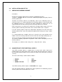
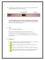
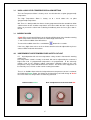
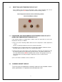
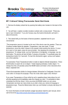
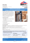
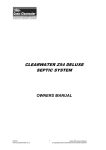
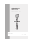
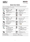
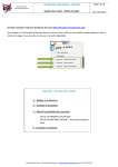
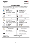
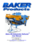
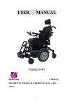
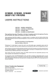
USER MANUAL
LEEC WARMING CABINET
W100, W157 and W330
CONTENTS
1)
GENERAL DESCRIPTION
2)
INSTALLATION AND SWITCHING ON WARMING
CABINET
3)
PROGRAMMING TEMPERATURE
4)
OVERTEMPERATURE CUT-OUT
5)
WARMING CABINET USEAGE
6)
CLEANING & DISINFECTING
7)
WARRANTY - PREVENTATIVE MAINTENANCE
v1.0 March 2009
LEEC Limited
Private Road No. 7
Colwick Industrial Estate
Nottingham
NG4 2AJ
Tel: 0115 961 6222
Fax: 0115 961 6680
E-mail: [email protected]
Website: www.leec.co.uk
1
1.0
GENERAL DESCRIPTION
Model W100
Model W157
Model W330
1.1
100 litre chamber capacity
157 litre chamber capacity
330 litre chamber capacity
CONSTRUCTION, HEATING AND INSULATION
Even heating throughout the entire chamber is ensured by the LEEC designed heating
element. The low wattage element is bonded to the outer surface of the chamber walls
ensuring quick heat conduction and low heating element temperature, only a few
degrees above the warming cabinet operating temperature.
New profiled resistive wire heating elements and high performance insulation ensure
optimum temperature control. All models have gentle fan assisted air circulation. This
ensures even temperature distribution throughout the chamber. Fast temperature
recovery keeps heat loss to a minimum after door opening.
1.2
TEMPERATURE CONTROLLER
A very easy to program electronic PID temperature controller is fitted to the LEEC
warming cabinet range.
This controller is easy to use and enables quick programming of the warming cabinet
chamber temperature.
In addition, this temperature controller has built in under temperature (low) level alarm
and over temperature (high) level alarm functions. The low and high level alarm limits
are factory set to +/- 2.0 °C above/below programmed temperature respectively after a
delay of 2 minutes.
1.3
INDEPENDENT OVER TEMPERATURE SAFETY CUT-OUT
An independent fail safe over temperature safety cut-out is fitted to this warming
cabinet. The over temperature cut-out is factory set to 40°C, but can be adjusted by the
customer, refer to section 4.3. In the extremely unlikely event of the warming cabinet
temperature controller failing on, the over temperature safety cut-out will disconnect the
heaters. This device, once tripped, has to be manually reset. Refer to section 3.6 for
instructions to reset.
1.4
CIRCULATION FAN
The internal fan helps to achieve accurate temperature uniformity throughout the inner
chamber. It also helps to enhance temperature recovery when the chamber is heavily
loaded. The fan is located at the top of the chamber. Air is drawn up through the
chamber, circulated around the full width ducting, and returned to the chamber floor.
The fan also improves temperature recovery after inner glass door opening. A micro
switch disconnects the fan upon opening the door to minimise temperature loss to the
chamber environment during door opening.
2
2.0
INSTALLATION AND SET UP
2.1
UNPACKING WARMING CABINET
Instructions:
Remove the warming cabinet from its protective cardboard packaging.
To do this, carefully undo one side of the cardboard packaging and gently slide the
warming cabinet out.
*Position the warming cabinet in the laboratory, either on the laboratory bench, or
under the bench. It is recommended that if the warming cabinet is to be placed under
the laboratory bench it is raised off the floor sufficiently to reduce the risk of
contamination from the floor entering into the warming cabinet inner chamber.
LEEC manufactures an under bench stand for the warming cabinet range to raise the
warming cabinet sufficiently off the floor. Please contact LEEC if this is required.
Level the warming cabinet using the 2 independent adjustable feet at the front of the
warming cabinet and secure this position by tightening the locking nut using a 10mm
spanner.
It is recommended that a bubble spirit level is placed in the centre position of the
middle shelf in the warming cabinet to check for level from left to right and front to rear.
*Please refer to your employers/organisation Safe Manual Handling Policy:
The Manual Handling Operations Regulations 1992, before attempting to lift the
warming cabinets.
The weights are as follows C100 – 54kg, C157 – 70kg and C330 – 107kg.
2.2
CONNECTION TO THE ELECTRICAL SUPPLY
Your LEEC warming cabinet is supplied with a 2 metre mains cable. Connect the
moulded plug to the 230V 50 Hz mains supply and the IEC connector to the socket at
the rear of the warming cabinet. Please make sure that the IEC connector is pushed in
securely.
The mains cable wiring is colour coded as follows: -
•
•
•
BROWN
BLUE
GREEN / YELLOW
=
=
=
LIVE
NEUTRAL
EARTH
Your LEEC warming cabinet requires a 230V 50Hz mains supply.
Once the warming cabinet is situated in the correct position in the laboratory, plug the
warming cabinet into a 230V 50Hz mains socket.
3
2.4
T o switch On the warming cabinet press in the Power button on the front facia panel.
This button will illuminate Green when power is On.
Front Facia Panel
Power On
The warming cabinet display will now light up displaying both the programmed
temperature (SET) and actual inner chamber temperature (ACT) and the Heater (H)
LED on the display indicates when the heaters are active. The warming cabinet will
now heat up to the programmed temperature.
2.5
Fuses
A 5 Amp fuse is fitted to the Mains Plug.
At the rear of the warming cabinet there are two internal protection fuses:
A 5 Amp internal fuse. This provides additional protection to the mains plug fuse.
A 3.15 Amp Heater fuse. This provides additional protection to the warming cabinet
heating elements.
2.6
Precautions
A qualified electrician or other competent person must carry out any
electrical work required to install the warming cabinet.
Do not place the warming cabinet in direct sunlight or near a heat source.
Make sure the warming cabinet is not standing on its electrical supply cable.
Before any cleaning or maintenance work is carried out, the mains supply
must be switched off and the plug removed from the electrical socket.
4
3.0
PROGRAMMING
3.1
TEMPERATURE DISPLAY
The programmed temperature, Set Point (SET) is displayed in Green and the Actual
Chamber Temperature inside the Warming cabinet Inner Chamber (ACT) is displayed
in Red
A Red LED Indicator next to the letter H (Heaters) on the display illuminates when the
heaters are on. When the chamber temperature is very close to programmed set point
temperature, it is normal to see this LED flashing.
A Red LED Indicator next to letter A (Alarm) on the display will illuminate if the
chamber warming cabinet temperature deviates to either the Low or High alarm limits
of +/- 2.0°C after a delay of 2 minutes.
3.2
TO PROGRAMME CHAMBER TEMPERATURE:
1. Press the
button on the controller once and release
2. SP1 in Flashing Red is now displayed on the screen.
3. Press either the ▲ button to increase the set point temperature or the ▼ button to
decrease the set point temperature.
Set Point Temperature is displayed in Green
4. Press the
button again to return to the normal screen that displays both the
Chamber Temperature in Red and Programmed Set Point in Green
5. *The Temperature can be programmed between a Set Point Temperature
of 20°C to a maximum of 60°C.
*The practical minimum operation temperature of the Warming cabinet is 5°C
above ambient temperature.
The warming cabinet is factory set to operate at +37.0°C unless otherwise
specified. Allow the temperature to stabilise for at least 24 hours before use.
5
3.3
HIGH & LOW LEVEL TEMPERATURE ALARM SETTING
The Low Temperature Alarm is factory set to - 2.0°C below the set point (programmed)
temperature.
The High Temperature Alarm is factory set to + 2.0°C above the set point
(programmed) temperature.
NB: There is a dwell period of 2 minutes factory programmed into the controller to allow
sufficient time for the chamber temperature to recover within the low / high alarm set
points; to prevent the alarm from activating immediately after the inner glass door is
closed.
3.4 AUDIBLE ALARM
A Red LED next to letter A (Alarm) on the display will illuminate if the chamber warming
cabinet temperature deviates to either the Low or High alarm limits of
+/- 2.0°C and an audible alarm will activate.
To cancel the audible alarm Press and hold the
button for 3 seconds.
If the Low / High alarm values or the 2 minutes dwell need to be adjusted then please
contact LEEC Limited for instructions.
4.0
INDEPENDENT OVER TEMPERATURE SAFETY CUT-OUT
4.1
An independent fail safe over temperature safety cut-out is fitted to this warming
cabinet. The
over temperature cut-out is factory set to 40°C, but can be adjusted by the customer if
higher than 37.0 °C programmed temperatures are programmed . In the extremely
unlikely event of the warming cabinet temperature controller failing on the over
temperature safety cut-out will disconnect the heaters. This device once tripped has to
be manually reset, refer to section 3.6 for resetting instructions.
There is an Audible Alarm when the independent over temperature cut-out is activated;
the illuminated Green Power On Switch on the front facia panel will change to Red in
the event of the over temperature cut-out being activated.
Normal Status Green
Over Temperature Cut-out Activated Red
6
4.2
RESETTING OVER TEMPERATURE CUT-OUT
In the unlikely event of the over temperature safety cut-out activating, this can be
reset by Pressing in the Red Button at the Back of the warming cabinet.
Over Temperature Cut-out at Rear of Warming cabinet
Push In Red Button to Reset
4.3
PROCEDURE FOR PROGRAMMING OVER TEMPERATURE CUT-OUT IF
OPERATING TEMPERATURE IS ABOVE 37.0°C
If the warming cabinet set temperature is above 37.0°C the procedure to set the over
temperature cut-out is as follows:
1) At the rear of the warming cabinet locate the over temperature cut-out adjustment
screw,
turn this screw fully clockwise to raise the cut-out to maximum
2) Programme new set point temperature on temperature controller. Allow time for the
warming cabinet to stabilise at this new set point temperature.
3) Gently turn the over temperature cut-out adjustment screw back (anti-clockwise) until
the warming cabinet over temperature cut-out activates. The Power switch on the
facia panel will illuminate RED and audible alarm sounds. Then gently increase the
over temperature cut-out by turning the adjustment screw a small increment
clockwise.
4) Press the Red reset button, refer to section 4.2.
5.0
WARMING CABINET USEAGE
To ensure that the temperature uniformity inside the inner chamber remains
within specification, it is important not to overload each shelf.
7
6.0
CLEANING and DISINFECTING
6.1
It is recommended that the exterior of the warming cabinet is kept clean by wiping over
with a non abrasive soft damp cloth using a warm soapy water solution. It is very
important to thoroughly dry the exterior after cleaning
6.2
It is advisable to clean the inner chamber regularly. To clean the inner chamber use a
70% isopropanol (alcohol) 30% distilled water solution. Apply using a sterile cloth so as
not to introduce any contamination and wipe over all the surfaces of the stainless steel
inner chamber.
The inner chambers of LEEC warming cabinets are made from the finest quality
stainless steel. However, corrosion can still result from improper use of fungicides and
bactericides. Never use any Chloride based chemicals for cleaning as this can result in
permanent damage to the stainless inner chamber and this is not covered by LEEC
warranty as no stainless steel is completely resistant to chlorine.
NB: Never use the following substances / chemicals / reagents to clean the stainless
steel inner chamber as permanent damage may result:
Sodium Azide
Aqua Regia
Iodine
Ferric Chloride
Sulphuric Acid
Always avoid any Chlorine based chemicals, including bleach.
7.0
WARRANTY - PREVENTATIVE MAINTENANCE
All LEEC Classic Warming cabinets are supplied with a 1 year manufacturer warranty.
Warranty Card – To register your warranty please fill in the User Guarantee
Registration Card and post to LEEC Limited, or to the Distributor that supplied your
warming cabinet if outside the United Kingdom.
All LEEC warming cabinets are built to the highest standards and all manufacturing
processes are compliant to ISO 9001.
All LEEC warming cabinets are built, fully tested then factory calibrated to UKAS
traceable standards.
This Classic Warming cabinet is built to last for many years, but to ensure this unit
continues to function at its optimum performance levels it is recommended that a
Preventative Maintenance Calibration Contract is purchased from LEEC Limited after
st
the units 1 year warranty period.
If the warming cabinet is outside the United Kingdom please contact the Distributor the
unit was purchased from for further information on Preventative Maintenance
Contracts.
8