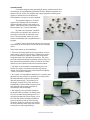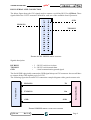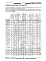
1
33 Questions per Minute
Relational Architecture 5
by Rafael Lozano-Hemmer
page
Concept notes ................................................................................... 01
Production ......................................................................................... 02
Exhibition history ............................................................................... 02
Collections ......................................................................................... 02
Credits ............................................................................................... 02
Selected reviews ............................................................................... 02
Installations notes ............................................................................. 03
Setup instructions
Connections .......................................................................
04
Serial links ..........................................................................
05
Power .................................................................................
05
Startup sequence ...............................................................
05
Shut down sequence .........................................................
06
LCDs ..................................................................................
06
Technical support ...............................................................
06
Podium ...............................................................................
06
Podium text ........................................................................
07
Preservation notes ............................................................................ 07
Wiring diagram ...................................................................
08
Interview for “Universes in Universe” ...............................................
09
APPENDIX I - Schematics of USB-RS485 board
USB-162 Main .................................................................... 13
USB-162 Connectors .........................................................
14
APPENDIX II - Information on Grifo LCD panels (63 pages) ............. 15
33 Questions per Minute 00
CONCEPT NOTES
A computer program uses grammatical rules to combine words from
the dictionary and automatically generates 55 billion different questions at a
speed of 33 per minute. The program has a large data bank containing the
majority of words found in the dictionary.
Each question is unique: it is never repeated.
The questions appear on 21 liquid
crystal micro-displays that are located at
different strategic points of the museum or
gallery. Each screen emits a faint beep with
each question, as if it were a detonator.
By means of a keyboard, members
of the public can introduce any question or
comment into the flow of automatic questions. Their participation shows up on the
screens immediately and is registered by the
program.
If the PC has an Internet connection, the texts can
simultaneously be mirrored to a URL that can be accessed
online.
Some observations on this installation:
• This piece is loosely based on the long tradition of automatic poetry. It is full of anti-content. It attempts to underline our incapability to respond, faced with an electronic
landscape made up of demands for attention. The piece
provides useless and slightly frustrating machine irony. Tireless grammatical algorithms perform a romantic and futile
attempt to pose questions that have never been asked.
• The effect of the installation is destabilising due to its
speed. The rhythm of questions excludes any rational
answer. 33 questions a minute is the threshold of legibility
– there is no time for reflection.
• To a viewer, it is impossible to determine if a question was
generated by the computer or entered by a human participant because both are shown at the same
rate and anonymously. The intention is to
develop a “reverse Turing Test” where the
impossibility to discriminate between human
and machine opens up the possibility of
concealment and camouflage.
• The majority of the automatic questions
are absurd: Will you bleed in an orderly fashion? Is the creator always being born? Do I
snip the marriage bed without rhyme or reason? But this surreal wordplay sometimes
turns up questions that do have meaning
within the context in which they are exhibited: Who bribes the artist? Why did computers become so self-congratulatory?
Views of preferred installation configuration. Dundee Contemporary
Art, Scotland, 2003. Photos by DCA.
33 Questions per Minute 01
Production
2000 in Spanish for the Havana Biennial
2001 in English for the Istanbul Biennial
2005 in German for the Postdamerplatz mediafaçade by realities:united
Exhibition History
Armory Show, NY, 2006
Postdamerplatz, mediafaçade with realities:united, Berlin, 2005-2006
ZKM, “The Algorithmic Revolution”, Karlsruhe, 2004-2007
Centro Cultural de España, Mexico City, 2005
Centro Atlántico de Arte Moderno, Las Palmas, 2005
MUSAC, León, 2005
Art Basel, Switzerland, 2004
ARCO Art Fair, Madrid, 2004
Art Basel Miami, USA, 2003
Laboratorio Arte Alameda, Mexico City, 2003
Bitforms Gallery, NY, 2003
Dundee Contemporary Art, “Ill Communication”, Scotland, 2003
Itau Cultural, “Emoçao Art.ficial”, Sao Paulo, 2002
Cibervisión 2, Conde Duque, Madrid, 2002
Istanbul Biennial, Turkey, 2001
Bienal de la Habana, Havana, 2000
Collections
The series consists of 5 copies and an artist proof. The initial sales were:
1/5 MUSAC Museum in León, Spain
2/5 Private collector in London, UK
3/5 Miami Art Central in Miami, USA
4/5 Private collector in Miami, USA
5/5 Museum of Modern Art in New York, USA
1 AP collection, the artist
Credits
The following should be credited in any information panels and catalogue:
Programmers: Conroy Badger and Rafael Lozano-Hemmer.
Languages: Susie Ramsay, Ana Parga, María Velarde Torres, Luis Jiménez-Carlés,
Luis Parga, Gabriela Raventós (for Spanish), Rebecca MacSween
(for English), Stephan Klinger, Sakrowski, Till Braband (for German).
Production: Conroy Badger, Will Bauer, Sandra Badger.
Selected Reviews
Zehar - Revista de Arteleku, no 57, San Sebastián, 2005
The Algorithmic Revolution Catalog, ZKM, Karlsruhe, 2004
Exit Revista de Arte, Madrid, February 2004
Cream3, Phaidon, London, 2003
The Guardian, London, 29 January 2003
The Herald, Glasgow, 7 February 2003
Felix “Risk”, NY, 2003
Art in America, NY, March 2002
BT, Tokyo, January 2002
Art in America, NY, October 2001
Egofugal catalog, Istanbul, 2001
Art Nexus, Miami, No.39, January-March 2001
El País, Madrid, 7 December 2000
Catálogo Bienal de la Habana, 2000
33 Questions per Minute 02
INSTALLATION NOTES
“33 Questions per Minute” consists of 21 LCDs (Liquid Crystal Displays) connected to a computer. Optionally the computer can also be connected to a large-scale display such as a projector, LED screen, media façade,
etc. Optionally the computer can also be connected to the Internet so that
people’s entries at the keyboard can be read online.
The LCDs should be hung on a wall in a random pattern with the
cables visible to give a “cloud-like” tableau, like a text bubble. The LCDs
should ideally be readable by short and tall
people so the placement should average
out at regular eye-level height. Alternatively,
long cables could be used to put the LCDs
in very disparate locations of the exhibition
space, like when we put a display on each
support column of the Wilfredo Lam Art
Center in Havana or at the Hagia Eirene in
Istanbul. This distribution should elicit the
feeling that the displays are “detonators”
that could blow up the building at any time.
If this option is preferred please note that it
will be necessary to provide additional DC
power for LCDs that are very far away from
the PC power supply.
Ideally the piece is not to be illuminated very brightly. The LCDs have an internal glow and it is nice when this is visible.
The podium for the keyboard can
be approximately 110 x 60 x 60 cm, with
space inside to fit and hide the laptop and
electronics. The LCD Power Supply can
be placed on the floor; an internal shelf is
required for the PC. The podium should be
painted white and the only visible elements
should be a feedback LCD (number zero)
which allows participants to see what they
are typing on the keyboard, the keyboard
and the text description of the piece. please
note that other podium layouts or styles can
be chosen by the curator.
Each LCD screen makes a quiet
beep every time a question is asked. If the
piezo speaker in each LCD is too loud, it can
be muffled with cotton inside of it then black
tape and then some cork to quiet it down.
The sound should only be audible from
about 2 or 3 metres away from the screens.
Views of site-specific installation. Istanbul Biennial, Turkey, 2001.
Photos by Lozano-Hemmer.
The piece saves a text file for every
day that it is in operation. This text “log”
contains any entries that people have entered in that day. You may choose to
upload these texts in a public web site by simply choosing to save the logs in
an online directory. To do this you may right click on the screen to see the
33 Questions per Minute 03
piece’s control panel, and choose a path to save the texts. Please note that
making the text entry public is optional. If this option is chosen, however, it is
essential that the typed input appear “as is”
uncensored and unformatted.
The computer can optionally be
connected to an external display such as a
projector, LED screen, media façade, video
wall or any other device that can show the
questions in a large or alternative format.
Ideally, this large scale presentation will
not be in the same room as the mini LCD
screens because the point of the small
screens is that the public needs to approach
for a more intimate experience which would
be defeated if we also have the large type.
Both mini LCD and large projection formats
can coexist in the same exhibition, for example, by putting the projected questions on
the exterior façade of the Museum and the
LCDs in one of the exhibition rooms.
Large-scale output using a projector. Centro Atlántico de Arte Moderno, Las Palmas, Canary Islands, Spain, 2005. Photos by CAA.
The installation can generate questions in English, Spanish and German. The curator can choose in the control panel exactly which languages
should be displayed and how often.
SETUP INSTRUCTIONS
Please open the box, pull out all the different elements and cables and
read this document in its entirety before proceeding.
Please connect and test the entire
installation before mounting on the wall.
> CONNECTIONS
1. Use the “Y” cable adapter provided to
connect the keyboard to the PC. Attach the
adapter connecter marked “M” to the keyboard cable and leave the connector marked
“K” unconnected (no, this is not a misprint!).
Plug the “M” connector of the “Y”
cable into the PS2 port (labelled “M”), located on the back of the PC in between the
power and USB connectors. The “K” connector may be used to connect an external PS2 mouse if you wish or you may
opt to use the built-in “TrackPoint” mouse controller for mouse navigation.
The “Trackpoint” control is the red button located in the middle of the PC’s
built-in keyboard
2. Connect the USB cable to the PC’s USB port (located on the back of the
PC). Run this cable to the smaller USB connector to the labelled USB port on
the wood-mounted green LCD controller board.
33 Questions per Minute 04
3. Make sure the PC-type power supply mounted on the wooden base along
with the green controller board is not turned on (the fan is not turning) or
plugged in. Do not turn on the LCD Power
Supply at this point!
> SERIAL LINKS
1. The 2 long grey wire links for the LCDs
are connected to the green controller board.
There is also a separate cable pair that is
used to link a single LCD that is used for the
input keyboard.
2. There are three LED lights on the controller board. The first — coloured red — is the
power LED, which confirms the power to the
micro-controller on the controller board. The
second is the yellow LED, which confirms the USB connection. The third is a
green data LED, which flashes whenever the controller board receives data
from the PC.
3. The LCDs are stored in anti-static bags. The LCDs have a numerical address and are labelled #0 to #10.
4. Note that there are 2 sets of #1 - #10 LCDs, as there are two separate grey
wire links. These LCDs should be connected in numeric sequence to each of
these two serial links. Each LCD on a link must have a unique number, so start
with LCD #1 at the end nearest to the controller board. LCD #10 should be the
furthest from the controller board.
5. There is only one zero (0) LCD; this LCD screen is mounted above the podium to give typing feedback to participants.
>
POWER
All the LCD displays must be connected before plugging the LCD
Power Supply (the big PC-type power supply mounted on the same wooden
base as the green controller board) into the mains. Never plug or unplug LCD
displays while the LCD Power Supply is turned on — this can permanently
damage the LCD displays.
Make sure that the LCD power supply box is set for the correct voltage setting for your local power. There is a Red switch on the back of it that
allows selection of 110V “North American” style power or 230 V power. This
must be set checked before proceeding! When correct, plug the LCD power
supply into the mains. Finally, plug the PC power supply in to the mains.
> STARTUP SEQUENCE
1 .Start the PC by pressing the POWER button (located directly below the “F9”
keyboard key on its built-in keyboard and labelled “Power”). Please lower the
screen to minimize reflection inside the podium.
2. Next, power up the LCD Power Supply via the ON/OFF switch located at
the rear of the box. You will hear a “chirp” from the displays as this power
comes on.
33 Questions per Minute 05
3. Once the PC has booted, it will automatically launch the “33 Questions Per
Minute” program, and questions will begin to appear in all 21 screens.
4. The “0” LCD will display the text typed on the keyboard. When the text
has been input, press the RETURN key. The “0” LCD screen will display a 10
second countdown, after which the text appears on all of the screens, before
being stored in the database.
> SHUT DOWN SEQUENCE
1. To turn the installation off, press STOP on the trackpad. (For testing the
work, double-click again to re-start the program).
2. Next, power off the computer by choosing “Shutdown” from the Windows
“Start” menu, located at the bottom Left of the PC screen (use the built-in
“TrackPoint” mouse controller for navigation).
3. Finally, power off the screens by turning off the LCD’s power supply via the
ON/OFF switch located at the rear of the box.
NEVER plug or unplug LCD displays while the LCD Power Supply is turned on
- this can permanently damage the LCD displays.
> LCDs
The 20 LCD screens can be hung as the curator best sees fit, but a
photograph of standard setup is included.
To mount the screens you may use long thin nails or aluminium wire
through the four eyelets on the corners of each LCD circuit board but please
be careful to ensure that the metal does not short the LCD circuitry.
Correct orientation of the LCD screens is with the
serial connector placed at the top right corner of the circuit
board.
> TECHNICAL SUPPORT
The purchase of the piece includes one installation
by a technician. During this visit the technician can train local staff on all aspects of the piece.
If you have any technical problems, you can reach
engineer Conroy Badger of APR, Inc. in Edmonton, Canada
at [email protected] or at Tel 780-450-8261. Alternatively you can call Lozano-Hemmer’s studio in Montreal at
514-597-0917.
We have included a backup of the software on
CDROM in case the PC needs to be replaced. Please keep
this somewhere accessible.
> PODIUM
Please hide the computer, power supply, cables,
controller board, and LCD Power Supply, etc. inside a podium, or behind a wall.
33 Questions per Minute 06
The only things visible on the podium should be:
1) feedback LCD screen, which allows
participant to see what s/he is typing
2) the keyboard
3) a descriptive text.
> PODIUM TEXT
If the piece is to be shown to the general public, this is the text that
could be printed and placed beside the podium. Please ensure it is clearly legible for the users.
“33 Questions per Minute, Relational Architecture 5”
by Rafael Lozano-Hemmer
This computer program uses grammatical rules to combine words from the dictionary and automatically generates
55 billion random questions at a speed of 33 per minute. The
software has been programmed to avoid repeating the same
question, and will take over 3 thousand years to present all the
possible word combinations.
If you would like to input a question, please type it on the
keyboard and press the Return key to send it to the screens.
Note: to delete a character, please press the “fn” and “Delete”
key.
PRESERVATION NOTES
The LCDs are manufactured by the Italian company Grifo; model
QTP6x4-C4 with an RS485 option. A detailed technical document on the displays, including all schematics, is enclosed as APPENDIX II. In the event that
one of the displays fails, a spare LCD screen is included, labelled #11. Grifo
can be contacted at www.grifo.it their telephone number is +39 51 89 20 52 in
Italy. If these displays are not available in the future they can be replaced with
any display that has a similar form factor provided that they can display nonascii character maps (in particular Spanish and German special characters),
provided that they have a piezo tweeter and provided that they can receive
5V power and data RS485 from our software. Please do not place the LCDs
inside a protective enclosure, the aesthetic of the piece is that the work has
been hand-made, low-tech, and in general with the aesthetics of a detonator.
The USB controller board is manufactured by APR inc. in Edmonton,
Canada. They can be contacted at [email protected] or by telephone at 780669-0529. The actual project engineer was Conroy Badger at conroy.badger@
shaw.ca or at Tel 780-450-8261. The schematics are enclosed as APPENDIX I.
33 Questions per Minute 07
The computer is an IBM ThinkPad running Windows 2000. The software
can run on Windows 2000 or XP and is programmed in Delphi. Source code is
provided so that the project can be recreated for future platforms if need be. The
software can be improved in the future by giving more robust “history” routines
to avoid repetition (currently we are limited by available computer power and
searches for billions of entries would be too slow, but surely in the future this will
be easier).
The keyboard is a Happy Hacking keyboard from PFU-Fujitsu. Information at http://www.pfu.fujitsu.com/hhkeyboard/. Any compact black keyboard
can be used for data entry, provided that it does not have function keys and
other distracting baloney.
The piece ships with all necessary connections made as in the following
wiring diagram.
Gnd
Gnd
From single
LCD line
RS-485+
RS-485+
RS-485-
RS-485-
5v DC
5v DC
5v DC
12v DC
Power
Supply
12v DC
Gnd
Gnd
Left RJ-45
Jack on USB
Board
To Link #1
10 LCDs
Gnd
RS-485+
RS-485+
RS-485-
RS-485-
12v DC
To single
LCD line
12v DC
Gnd
Gnd
Gnd
Right RJ-45
Jack on USB
Board
RS-485+
RS-485+
RS-485-
RS-485-
33 Questions per Minute 08
To Link #2
10 LCDs
INTERVIEW FOR “UNIVERSES IN UNIVERSE”
Q: Why did you decide to bring this piece to the Havana Biennial, and how
does it work?
I call “relational architecture” the kind of interactive installations in
public space that I have been doing for the past four or five years. The work
normally involves the transformation of emblematic buildings using new
technologies - typically projections, sound, 3D sensors, robotics. The curators
of the Biennial had seen some of my work
through video documentation and asked
me to do something in the streets, a kind of
urban transformation project like the one I
did in Mexico City for the Millennium. While I
would have been delighted to do that, I also
knew that it was very expensive to accomplish that kind of very ambitious show. So I
designed a very small, intimate piece, one
that was portable so I could bring it easily
here.
I wanted a technology that had a
ubiquitous, “anti-monumental” character, so
I brought 21 tiny liquid crystal displays (LCD screens) and
placed them on the supporting columns of the Wilfredo Lam
Center. Poet Alejo Carpentier said that Havana was the city
of columns and I was interested in the idea of working with
this architectural support. The screens are connected to a
laptop computer with a custom-made grammatical software program. Basically it’s an algorithm that uses random
access of words from a dictionary to form new sentences.
It knows how to conjugate verbs and how to add adverbs,
adjectives, articles and so forth. Currently, because of the
number of words that I have in the database, it can generate
16 billion different questions that are unique and grammatically correct. When you look at some of these questions,
they are completely absurd, like “¿Cuándo sangrarás de
forma ordenada” (When will you bleed in an orderly fashion?). And then there are some that could
be construed as having some relevance, like
“¿Porqué nos siguen sobornando los artistas?” (Why do artists continue bribing us?).
The installation shows 33 questions
per minute, which is the threshold of readability, so the experience is irritating to the
extent that there is no time for reflection, like
in our current media culture. This irritation is
magnified by the fact that the screens beep
each time a question appears. Cuban artist
Glenda Leon remarked that the installation sounds like the countdown for a bomb,
- which is an interpretation that I like very
much.
Bienal de la Habana, Havana, Cuba, 2000. Photos by Lozano-Hemmer.
33 Questions per Minute 09
Q: How is the people’s interaction supposed to be?
There is a keyboard that people can use to add their own comments
or questions and interrupt the flow of automatic questions.
Q: But for instance my question would be
one of those that would make sense in this
automatic flow or would it be taken apart?
No. It will appear exactly as you
typed it, but within the flow of the other
questions. So if you wrote something that
makes sense then it would make sense to
other people. But also most of the questions
that the machine asks make some kind of
sense. So one interesting effect, which I was
looking for with the speed of the questions,
is the possibility for camouflage. If people
write something that is disturbing or taboo
Galerie Guy Bärtschi, Geneva, 2005. Photos by RLH.
or anything that can be considered problematic, this can be concealed within all of
the automatic questions. The concealment happens because it is impossible
to ascertain which questions have been generated by people and which have
been generated by computer. Like a reverse Turing test.
I’m interested in that kind of de-authoring of the words as a phenomenon. Originally I wanted people to participate and for their input to be presented not only on the LCD screens but also
on the Internet in real time. Unfortunately the
Internet connection was not possible it in
Cuba. So the system is recording everything
people are writing and when the installation
returns to me, I’m going to upload all of the
text onto the Internet. Of course, people
who participate know that their comments
will be taken to the Internet and I am curious
to see how that affects what they say, in a
country with no local public Internet access... I saw a bit of it and it is very interesting and very eccentric stuff!
Laboratorio Arte Alameda, Mexico City, 2003. Photos by RLH.
And I think that I’ll continue this kind
of work - the work about automatic texts
- because, like I said, it asks fundamental questions about what our expectation is from technology. Some of the people I’ve met here in Cuba have a real
concern - and of course it’s very well founded - that they’re not getting enough
information, which obviously hopefully will be remedied. However, in western
countries, I feel that there’s almost too much information. I feel like there is a
level at which there is a saturation and a density that renders us useless.
Q: Is there a personal history behind the piece?
Yes, although by no means do I want to make it sound as though the
piece is the natural result of that personal anecdote, but it definitely did affect
me.
33 Questions per Minute 10
My father, a chain-smoker, got lung cancer suddenly. I was told he had
only two weeks more to live. When I arrived in Mexico he already was on a life
support system in the intensive care unit. I didn’t really know my dad - my parents divorced when I was very little, - and there was so much I wanted to ask
him. Unfortunately he couldn’t speak because of the respirator tube coming
out of his mouth, and he was too tired to write. So I made a small table with
an alphabet where he could point at the letters and make words and talk to
me that way. But that became pretty tedious and I had to make a new version
of the table, but this time with words, subjects, nouns. Then it dawned on me
- who should choose these words? Who should be the author of the textual
puppetry? Should I be choosing words such as “death”? Should I be choosing
words such as “fear”? I became a bit obsessed with the word selection and
finally presented the new table to him. Well, I failed. The word that was in fact
in his mind, as I finally found out later from my mother, was the word “sex”. He
was sitting there for weeks in a room with thirty people and what he wanted
was to take a good look at the nurse. It would have never occurred to me in
such a situation! I had my own agenda about what I wanted him to say and I
missed the point entirely. It’s interesting how wrong we can be in our assumptions. Now I’m interested in the room to be undermined, room to acknowledge
that any kind of proposal should always has space for contravening.
Q: At this stage you were already designing the software?
No, this happened six years ago. The work with software to combine
words only started about a year ago. But it is connected, I think. To some degree I believe that there is a certain arbitrary quality to words. And I do agree
with the observation that words and meanings are not necessarily connected;
they do sort of float. What makes it real is the body. What makes it real is life
and death.
© Pat Binder & Gerhard Haupt, Universes in Universe
Large-scale output using a media façade. Postdamerplatz, mediafacade with realities:united, Berlin
2005-2006. Photos by RLH.
33 Questions per Minute 11
APPENDIX I
schematics of USB-RS485 board
33 Questions per Minute 12
33 Questions per Minute 13
A
B
C
D
Vcc
1
5
Vcc
100nF
C3
Data
Add
2
SLP
S/W
Vcc 5v
J5
JUMPER
LED
D1
R5
510
5
LED
D2
R6
510
1
2
3
4
5
6
7
8
9
10
11
12
1
2
3
4
5
6
7
8
9
10
11
12
Vcc
A8
A9
WE#
OE#
A10
CE#
D7
D6
D5
D4
D3
CY7C128A
A7
A6
A5
A4
A3
A2
A1
A0
D0
D1
D2
Gnd
U2
DLP-USB245M
Board ID
Gnd
Reset #
Reset Out#
Ground
3.3v Out
Ground
Sleep
Send/Wup
Vcc I/O
Ext Vcc
Port Vcc
U6
4
24
23
22
21
20
19
18
17
16
15
14
13
D0
D1
D2
D3
D4
D5
D6
D7
RD#
WR
TxE#
RxF#
4
VCC
24
23
22
21
20
19
18
17
16
15
14
13
B4
B0
B1
Data
RD#
WR
TxE#
RxF#
Add
Data
SCK
3
3
33pF
C4
C8
1uF
LED
D3
R4
510
47K
R1
X1
Date:
Size
A
Title
Tx0
C5
1
2
3
4
5
6
7
8
9
10
11
12
13
14
15
16
17
18
19
20
PB0
PB1
PB2
PB3
PB4
PB5
PB6
PB7
RESET
PD0
PD1
PD2
PD3
PD4
PD5
PD6
PD7
XTAL2
XTAL1
GND
Vcc
PA0
PA1
PA2
PA3
PA4
PA5
PA6
PA7
PE0
PE1
PE2
PC7
PC6
PC5
PC4
PC3
PC2
PC1
PC0
Sunday, January 02, 2005
2
40
39
38
37
36
35
34
33
32
31
30
29
28
27
26
25
24
23
22
21
Vcc
Page 1 of 1
Sheet
USB-162 Main
ATmega162-DIL40small
U3
Document Number
RD#
WR
TxE#
RxF#
SLP
S/W
Rx0
B0
B1
Rx1
Tx1
B4
Mosi
Miso
33pF
16 MHz
VCC
2
Data
Add
1
1
1
of
1
Rev
1.0
A
B
C
D
A
B
C
7-12v DC
J1
5
PB6(MISO)
PB7(SCK)
Reset
2
1
V In
1
In
U1
Out
1
3
5
LM7805
J5
3
SPI
2
4
6
+
Vcc
C2
100uF
Vcc 5v
4
PB5(MOSI)
4
1
2
D
5
Gnd
2
C1
100nF
J10
JUMPER
Miso - PB6
Mosi - PB5
3
3
Rx0
Tx0
Tx1
Rx1
1
2
3
4
1
2
3
4
Vcc
B
A
Gnd
Vcc
B
A
Gnd
Date:
Size
A
Title
SN75176
RO
RE/
DE
DI
U5
SN75176
RO
RE/
DE
DI
U4
8
7
6
5
8
7
6
5
C7
C6
Vcc
V In
Vcc
V In
1
2
3
4
5
6
7
8
1
2
3
4
5
6
7
8
Sunday, January 02, 2005
2
Page 2 of 2
USB-162 Connectors
RS-485 -
Gnd
RS-485 +
100nF
RS-485 -
Gnd
RS-485 +
100nF
Document Number
Vcc
Vcc
2
Sheet
RJ-45
J9
RJ-45
J8
1
2
1
1
2
33 Questions per Minute 14
1
of
J7
JUMPER
R3
120
J6
JUMPER
R2
120
1
1
Rev
1.0
A
B
C
D
APPENDIX II
information on Grifo LCD panels
33 Questions per Minute 15
QTP 4x6
Quick Terminal Panel 4x6 Keys
USER MANUAL
Via dell' Artigiano, 8/6
® 40016 San Giorgio di Piano
(Bologna) ITALY
ITALIAN TECHNOLOGY
E-mail: [email protected]
http://www.grifo.it
http://www.grifo.com
Tel. +39 051 892.052 (r.a.) FAX: +39 051 893.661
grifo
QTP 4x6
Rel. 5.10
Edition 27 March 2003
®
®
, GPC , grifo , are trade marks of grifo®
QTP 4x6
Quick Terminal Panel 4x6 Keys
USER MANUAL
Front size equal to the size of the display being used; remarkably low price; the User
panel is available mounting on of these Displays:
QTP 4x6-C2: LCD display, back lighted or not, with 2 lines of 20 chars
QTP 4x6-C4: LCD display, back lighted or not, with 4 lines of 20 chars
QTP 4x6-C4B: LCD display, back lighted or not, with 4 lines of 20 chars,bigger
QTP 4x6-C24:LCD display, back lighted or not, with 2 lines of 40 chars
QTP 4x6-F2: Fluorescent display with 2 lines of 20 characters
QTP 4x6-F4: Fluorescent display with 4 lines of 20 characters
QTP 4x6-F24: Fluorescent display with 2 lines of 40 characters
Buzzer programmable as BELL or to sound with keystroke; complete management
of 24 keys trough external 4x6 matrix keyboard; autorepeat and keyclick functions;
E2 up to 2 Kbyte for permanent storage of set-up, messages, key codes,etc.;
memorization on E2 and visualization, also sliding, of up to 97 messages; RS 232
or optional RS 422, RS 485 or Current Loop serial line; communication
configurable as Point-to-point or Master-Slave; local set up for communication
parameters (Baud Rate, Stop bits,Keyclick, etc.); up to eight characters pattern is
user defineable; up to 255 different characters in display character memory that
can be displayed; possibilty to order some models with QTP 42144 and QTP 96192
containers; unique +5 Vdc power supply
Via dell' Artigiano, 8/6
® 40016 San Giorgio di Piano
(Bologna) ITALY
ITALIAN TECHNOLOGY
E-mail: [email protected]
http://www.grifo.it
http://www.grifo.com
Tel. +39 051 892.052 (r.a.) FAX: +39 051 893.661
grifo
QTP 4x6
Rel. 5.10
Edition 27 March 2003
®
®
, GPC , grifo , are trade marks of grifo®
DOCUMENTATION COPYRIGHT BY grifo® , ALL RIGHTS RESERVED
No part of this document may be reproduced, transmitted, transcribed, stored in a
retrieval system, or translated into any language or computer language, in any form or
by any means, either electronic, mechanical, magnetic, optical, chemical, manual, or
otherwise, without the prior written consent of grifo®.
IMPORTANT
Although all the information contained herein have been carefully verified, grifo®
assumes no responsability for errors that might appear in this document, or for damage
to things or persons resulting from technical errors, omission and improper use of this
manual and of the related software and hardware.
grifo® reserves the right to change the contents and form of this document, as well as the
features and specification of its products at any time, without prior notice, to obtain
always the best product.
For specific informations on the components mounted on the card, please refer to the
Data Book of the builder or second sources.
SYMBOLS DESCRIPTION
In the manual could appear the following symbols:
Attention: Generic danger
Attention: High voltage
Trade Marks
, GPC®, grifo® : are trade marks of grifo®.
Other Product and Company names listed, are trade marks of their respective companies.
grifo®
ITALIAN TECHNOLOGY
GENERAL INDEX
INTRODUCTION ........................................................................................................................ 1
FIRMWARE VERSION .............................................................................................................. 1
GENERAL INFORMATION ...................................................................................................... 2
SERIAL COMMUNICATION ............................................................................................... 3
BUZZER ................................................................................................................................... 3
KEYBOARD ............................................................................................................................ 3
DISPLAY .................................................................................................................................. 4
EEPROM .................................................................................................................................. 4
TECHNICAL FEATURES .......................................................................................................... 6
GENERAL FEATURES .......................................................................................................... 6
PHYSICAL FEATURES ......................................................................................................... 6
ELECTRIC FEATURES ........................................................................................................ 7
INSTALLATION .......................................................................................................................... 8
CN3 - INTERFACE CONNECTOR ...................................................................................... 8
POWER SUPPLY CONNECTION .................................................................................. 8
RS 232 SERIAL LINE CONNECTION ............................................................................ 9
RS 422 SERIAL LINE CONNECTION .......................................................................... 10
RS 485 SERIAL LINE CONNECTION .......................................................................... 12
CURRENT LOOP SERIAL LINE CONNECTION ...................................................... 14
EXTERNAL MATRIX KEYBOARD CONNECTION ................................................. 18
SERIAL LINE CONFIGURATION .................................................................................... 20
CONTRAST REGULATION TRIMMER .......................................................................... 20
SOFTWARE DESCRIPTION ................................................................................................... 21
LOCAL SET UP .................................................................................................................... 21
RECEIVE BUFFER .............................................................................................................. 22
KEYBOARD ACQUISITION .............................................................................................. 22
KEYS CODES ............................................................................................................................ 23
COMMUNICATION MODALITIES .................................................................................. 24
MASTER SLAVE COMMUNICATION MODE .................................................................... 24
CHARACTERS VISUALIZATION ON THE DISPLAY.................................................. 26
DATA STORED IN EEPROM ............................................................................................. 27
COMMANDS FOR CURSOR POSITION ......................................................................... 28
CURSOR LEFT ................................................................................................................ 28
CURSOR RIGHT ............................................................................................................. 28
CURSOR DOWN .............................................................................................................. 28
CURSOR UP...................................................................................................................... 28
HOME ................................................................................................................................ 28
CARRIAGE RETURN ..................................................................................................... 29
CARRIAGE RETURN+LINE FEED ............................................................................. 29
ABSOLUTE CURSOR PLACEMENT .......................................................................... 29
QTP 4x6
Rel. 5.10
Page I
grifo®
ITALIAN TECHNOLOGY
COMMANDS FOR CHARACTERS ERASURE .............................................................. 30
BACKSPACE .................................................................................................................... 30
CLEAR PAGE ................................................................................................................... 30
CLEAR LINE .................................................................................................................... 30
CLEAR END OF LINE .................................................................................................... 30
CLEAR END OF PAGE ................................................................................................... 30
COMMANDS FOR CURSOR ATTRIBUTES MANAGEMENT .................................... 31
CURSOR OFF ................................................................................................................... 31
STEADY STATIC CURSOR ON .................................................................................... 31
BLINKING BLOCK CURSOR ON ................................................................................ 31
COMMANDS FOR EEPROM ............................................................................................. 32
REQUEST FOR EEPROM WRITING POSSIBILITY................................................ 32
WRITING OF PRESENCE BYTE ................................................................................. 32
READING OF PRESENCE BYTE ................................................................................. 32
COMMANDS FOR GENERAL FUNCTIONS .................................................................. 33
READING OF VERSION NUMBER ............................................................................. 33
BEEP .................................................................................................................................. 33
OPERATING MODE SELECTION ............................................................................... 33
COMMANDS FOR KEYBOARD MANAGEMENT ........................................................ 34
KEY RECONFIGURATION ........................................................................................... 34
KEYCLICK ON WITHOUT MEMORIZATION ......................................................... 34
KEYCLICK OFF WITHOUT MEMORIZATION ....................................................... 34
KEYCLICK ON WITH MEMORIZATION ................................................................. 35
KEYCLICK OFF WITH MEMORIZATION................................................................ 35
COMMANDS FOR USER CHARACTERS ....................................................................... 36
DEFINITION OF USER CHARACTER ........................................................................ 37
DEFINITION AND MEMORIZATION OF USER CHARACTER ............................ 37
COMMANDS FOR MESSAGE MANAGEMENT ........................................................... 38
READING OF THE LAST STORAGED MESSAGE NUMBER ................................ 38
MESSAGE STORAGE ..................................................................................................... 38
MESSAGE READING ..................................................................................................... 39
MESSAGE VISUALIZATION ........................................................................................ 39
SCROLLING MESSAGE VISUALIZATION ............................................................... 40
EXTERNAL CARDS ................................................................................................................. 41
APPENDIX A: COMMAND CODES SUMMARY TABLES .............................................. A-1
APPENDIX B: DISPLAY CHARACTERS ........................................................................... B-1
APPENDIX C: MOUNTING OUTLINE DIMENSIONS .................................................... C-1
APPENDIX D: ALPHABETICAL INDEX ............................................................................ D-1
Page II
QTP 4x6
Rel. 5.10
grifo®
ITALIAN TECHNOLOGY
FIGURES INDEX
FIGURE 1: QTP 4X6 PHOTO IN ALL AVAILABLE MODELS ..................................................................... 5
FIGURE 2: CURRENT CONSUMPTION TABLE ........................................................................................ 7
FIGURE 3: CN3 - POWER SUPPLY PINS .............................................................................................. 8
FIGURE 4: CN3 - RS 232 SERIAL LINE PINS ..................................................................................... 9
FIGURE 5: RS 232 SERIAL CONNECTION EXAMPLE ............................................................................. 9
FIGURE 6: CN3 - RS 422 SERIAL LINE PINS ................................................................................... 10
FIGURE 7: RS 422 SERIAL CONNECTION EXAMPLE ........................................................................... 11
FIGURE 8: COMPONENTS MAP OF COMPONENTS SIDE ........................................................................ 11
FIGURE 9: CN3 - RS 485 SERIAL LINE PINS ................................................................................... 12
FIGURE 10: RS 485 POINT-TO-POINT SERIAL CONNECTION EXAMPLE ............................................... 12
FIGURE 11: RS 485 NETWORK CONNECTION EXAMPLE .................................................................... 13
FIGURE 12: CN3 - CURRENT LOOP SERIAL LINE PINS ...................................................................... 14
FIGURE 13: CURRENT LOOP 2-WIRES POINT-TO-POINT CONNECTION EXAMPLE .................................. 15
FIGURE 14: CURRENT LOOP 4-WIRES POINT-TO-POINT CONNECTION EXAMPLE .................................. 15
FIGURE 15: CURRENT LOOP NETWORK CONNECTION EXAMPLE ......................................................... 16
FIGURE 16: JUMPERS, CNNECTORS, TRIMMER, ETC. LOCATION ......................................................... 17
FIGURE 17: CN3 PINS TO CONNECT AN EXTERNAL MATRIX KEYBOARD TO QTP 4X6 ........................ 18
FIGURE 18: EXTERNAL MATRIX KEYBOARD CONNECTION ................................................................. 19
FIGURE 19: USER JUMPERS DESCRIPTION TABLE .............................................................................. 20
FIGURE 20: DEFAULT KEY CODES .................................................................................................... 23
FIGURE 21: EXAMPLE OF MASTER SLAVE COMMUNICATION .............................................................. 25
FIGURE 23: USER CHARACTERS MODEL ........................................................................................... 36
FIGURE 24: NUMBER OF MESSAGES STORAGEABLE ON EEPROM ................................................... 38
FIGURE 25: AVAILABLE CONNECTIONS DIAGRAM ............................................................................. 43
FIGURE A1: COMMAND CODES SUMMARY TABLE (1 OF 2) .............................................................. A-1
FIGURE A2: COMMAND CODES SUMMARY TABLE (2 OF 2) .............................................................. A-2
FIGURE B1: QTP 4X6-F2, F4, F24 CHARACTERS TABLE .............................................................. B-1
FIGURE B2: QTP 4X6-C4B, C24 CHARACTERS TABLE ................................................................. B-2
FIGURE B3: QTP 4X6-C2, C4 CHARACTERS TABLE ...................................................................... B-3
FIGURE C1: QTP 4X6-C2, F2 DIMENSIONS .................................................................................. C-1
FIGURE C2: QTP 4X6-C4, F4 DIMENSIONS .................................................................................. C-2
FIGURE C3: QTP 4X6-C4B DIMENSIONS ..................................................................................... C-3
FIGURE C4: QTP 4X6-C24, F24 DIMENSIONS .............................................................................. C-4
QTP 4x6
Rel. 5.10
Page III
ITALIAN TECHNOLOGY
grifo®
INTRODUCTION
The use of these devices has turned - IN EXCLUSIVE WAY - to specialized personnel.
The purpose of this handbook is to give the necessary information to the cognizant and sure use of
the products. They are the result of a continual and systematic elaboration of data and technical tests
saved and validated from the manufacturer, related to the inside modes of certainty and quality of
the information.
The reported data are destined- IN EXCLUSIVE WAY- to specialized users, that can interact with
the devices in safety conditions for the persons, for the machine and for the enviroment, impersonating
an elementary diagnostic of breakdowns and of malfunction conditions by performing simple
functional verify operations , in the height respect of the actual safety and health norms.
The informations for the installation, the assemblage, the dismantlement, the handling, the adjustment,
the reparation and the contingent accessories, devices etc. installation are destined - and then
executable - always and in exclusive way from specialized warned and educated personnel, or
directly from the TECHNICAL AUTHORIZED ASSISTANCE, in the height respect of the
manufacturer recommendations and the actual safety and health norms.
The devices can't be used outside a box. The User must always insert the cards in a container that
rispect the actual safety normative. The protection of this container is not threshold to the only
atmospheric agents, but specially to mechanic, electric, magnetic, etc. ones.
To be on good terms with the products, is necessary guarantee legibility and conservation of the
manual, also for future references. In case of deterioration or more easily for technical updates,
consult the AUTHORIZED TECHNICAL ASSISTANCE directly.
To prevent problems during card utilization, it is a good practice to read carefully all the informations
of this manual. After this reading, the User can use the general index and the alphabetical index,
respectly at the begining and at the end of the manual, to find information in a faster and more easy
way.
FIRMWARE VERSION
This handbook make reference to firmware version 1.3 and following ones. The validity of the
information contained in this manual is subordinated to the firmware release number, so the user must
always verify the correct correspondence beetween the notations. Inside the device, the firmware
release number is written on the label stuck on the CPU or it can be obtained by a proper command
sent through the serial line.
QTP 4x6
Rel. 5.10
Page 1
grifo®
ITALIAN TECHNOLOGY
GENERAL INFORMATION
QTP 4x6 is a complete low cost operator panel with small overall dimension, specifically designed
for industrial use and for direct mounting on automatic machinery. It is a video terminal suitable to
be the direct interface between operator and machinery in any of the control, command, visualization
operations which could be necessary in many civil and/or industrial applications.
QTP 4x6 is available with alphanumeric Fluorescent or LEDs back lite LCD displays, with 20
characters for 2 or 4 lines or with 40 characters for 2 lines. QTP 4x6 is directly connected with the
display, so it has an overall frontal dimension equal to the selected display used for visualization. For
the mechanic fixing the user must use the onboard displays holes.
QTP 4x6 is the best choice whenever the User needs to show messages and 24 keys are enough to
interact with the hardware.
QTP 4x6 gives the possibility to store in the on board serial EEPROM up to 97 messages. These
messages can be shown on the display, also in sliding mode, simply sending to the serial port a proper
sequence of commands. This way, the amount of work for the main CPU is lowered, also the
messages to show must not be sent through the serial line to the panel.
It is also possible to read, through the serial line, the messages stored in the EEPROM. This allows
the User to employ QTP 4x6 as a small storage device where special data like hardware Set-Up,
passwords, ID codes, etc. can be stored.
Some models of QTP 4x6 can be enclosed inside a proper metallic container, named QTP 72144
and QTP 96192, obtaining a compact apparatus with IP 56 frontal protection and with remarkable
mounting facilities.
The QTP 4x6 is able to execute an entire range of display commands, including Clear Screen,
Position cursor, EEPROM reading or writing, etc., with code compatibility to ADDS ViewPoint
standard video terminal. Features of QTP 4x6, including options, are as follows:
- Front size equal to the size of the display being used
- Remarkably low price
- The User panel is available mounting on of these Displays
QTP 4x6-C2: LCD display, back lighted or not, with 2 lines of 20 chars
QTP 4x6-C4: LCD display, back lighted or not, with 4 lines of 20 chars
QTP 4x6-C4B: LCD display, back lighted or not, with 4 lines of 20 chars, bigger format
QTP 4x6-C24:LCD display, back lighted or not, with 2 lines of 40 chars
QTP 4x6-F2: Fluorescent display with 2 lines of 20 characters
QTP 4x6-F4: Fluorescent display with 4 lines of 20 characters
QTP 4x6-F24: Fluorescent display with 2 lines of 40 characters
- Buzzer programmable as BELL or to sound with keystroke
- Complete management of 24 keys trough external 4x6 matrix keyboard
- Autorepeat and keyclick functions
- E2 up to 2 Kbyte for permanent storage of set-up, messages, key codes,etc.
- Memorization on E2 and visualization, also sliding, of up to 97 messages
- RS 232 or optional RS 422, RS 485 or Current Loop serial line
- Communication configurable as Point-to-point or Master-Slave
- Local set up for communication parameters (Baud Rate, Stop bits,Keyclick, etc.)
- Up to eight characters pattern is user defineable
- Up to 255 different characters in display character memory that can be displayed
- Possibilty to order some models with QTP 42144 and QTP 96192 containers
- Unique +5 Vdc power supply
Page 2
QTP 4x6
Rel. 5.10
ITALIAN TECHNOLOGY
grifo®
Here follows a description of the board's functional blocks, with an indication of the operations
performed by each one.
SERIAL COMMUNICATION
The communication with remote units is by standard RS 232 serial line, but it can be optionally
changed in RS 422, RS 485 or Current Loop.
Communication mode can be point-to-point or Master-Slave, employing the nineth-bit techinque;
communication protocol is 8 (point-to-point) or 9 (Master-Slave) Bit, no parity, Baud Rate selectable
amongst 1200, 2400, 4800, 9600, 19200 and 38400 Baud and Stop bit selectable amongst 1, 2.
All these parameters are defined through set up mode.
BUZZER
QTP 4x6 has a circuitery that generates a steady sound, based on a capacitive buzzer. The said
circuitery can be activated by software through a specific comand for generating a simple beep or
it can be linked to a key pressure, just to get the keyclick function, or it can signalize possible
malfunctions.
In the last case when, after a power on, the card generates an intermittent sound and it doesn't work
correctly, there is a wrong condition that must be resolved: please contact grifo® technicians.
KEYBOARD
QTP4x6 has an interface for a 4x6 external matrix keytboard with 24 keys made by normally- open
contacts. The keys management is completely automatic with comfortable autorepeat feature, and
there is also the possibility to change the code returned on the serial line for each key stroke, through
software by using a proper command. Furthermore there is the possibility to switch on/off the key
click function, i.e the buzzer activation each time a key is pressed.
Four of these keys are used to enter in the local setup function, please refer to paragraph “LOCAL
SET UP”.
Thanks to the management of this simple keyboard, the QTP 4x6 can cheaply solve the data
exchange problems especially when those data are homogeneous and easy. By using industrial keys
and push buttons the problems can be solved even in strong environmental applications and
functionality is guaranteed in each operating conditions.
QTP 4x6
Rel. 5.10
Page 3
grifo®
ITALIAN TECHNOLOGY
DISPLAY
QTP 4x6 is available with Fluorescent or backlite LCD alphanumeric displays with different
characters number and different characters size. In detail the following displays can be mounted:
Fluorescent 20x2, Fluorescent 20x4, Fluorescent 40x2, LCD 20x2, LCD 20x4, LCD 20x4 big or
LCD 40x2 characters. The LEDs backlight of LCD models ensures a good visibility even when the
environmental lighting changes and if it necessary the user can modify the contrast regulation by
acting on a specific trimmer. Another important features of QTP 4x6 displays is their wide viewing
angle that allows a good visibility from each frontal position. Further information on each display
are reported in “TECHICAL FEATURES” chapter.
The user must choose the right display (so the right QTP 4x6 model) that is sufficient for the
information to visualize and for his visibility requirements. For specific requirements on current
consumption, visibility and price the card can be provided with LCD display not backlighted: for
detailed information about these options and their availability, please contact directly grifo® offices.
EEPROM
QTP 4x6 has on board EEPROM (the size vary from 256 Bytes to 2 KBytes) for storing set up,
communication protocol, keys codes, messagges, and so on. Many of the stored data have vital
importance so a serial EEPROM has been choosen to obtain the best warranties on validity and
maintenance of the saved information, even when power supply is not available.
It is possible to memorize up to 97 messages of 20 characters that can be first saved on EEPROM
and then read or shown on the display at any moments , just giving a proper command to the terminal,
with the right message identification number.
QTP 4x6 also manages scrolling messages, to show on an unique line more text than it could be
visible without scrolling.
For detailed information about messages please read “COMMANDS FOR MESSAGES
MANAGEMENT” paragraph.
The EEPROM size must be chosen considering the application to realize or the specific requirements
of the user. Normally the card is equipped with 512 Bytes of EEPROM and the other configuration
must be specified from the user, at the moment of the order, by using the following indications:
2048 Bytes EEPROM
Page 4
->
.MEX option
QTP 4x6
Rel. 5.10
grifo®
ITALIAN TECHNOLOGY
QTP 4x6-C2
QTP 4x6-C4
QTP 4x6-C4B
QTP 4x6-C24
QTP 4x6-F2
QTP 4x6-F4
QTP 4x6-F24
FIGURE 1: QTP 4X6 PHOTO IN ALL AVAILABLE MODELS
QTP 4x6
Rel. 5.10
Page 5
grifo®
ITALIAN TECHNOLOGY
TECHNICAL FEATURES
GENERAL FEATURES
On board resources:
10 signals for external 4x6 matrix keyboard management
Buzzer for bell and keyclick
Full duplex RS 232, RS 422, RS 485 or current loop serial line
EEPROM for set up, messagges and so on (2K Bytes max.)
Alphanumeric display in 7 different models
Trimmer for contrast regulation of LCD display
Displays:
LCD :
Fluorescent:
20x2, 20x4, 20x4 big or 40x2, with LEDs
backlite
20x2, 20x4 or 40x2
CPU:
89C4051 with 14.7456 MHz Crystal.
Communication protocol:
Baud rate:
Stop bit:
Parity:
Bits x chr:
Default:
Com logic protocol:
Selectable between normal and master slave (Default: normal)
Receive buffer dimension:
30 characters
1200, 2400, 4800, 9600, 19200, 38400
1 or 2
none
8, 9
19200 Baud, 1 Stop, No parity, 8 Bits
PHYSICAL FEATURES
Size:
Display 20x2: 116 x 37 x 30 mm (W x H x D)
Display 20x4:
98 x 61 x 30 mm (W x H x D)
Display 20x4 big:146 x 63 x 28 mm (W x H x D)
Display 40x2: 182 x 34 x 34 mm (W x H x D)
See outline dimension in APPENDIX C
Characters size:
LCD 20x2:
5 x 7 dots, 3.20 x 4.85 mm (W x H)
LCD 20x4:
5 x 7 dots, 2.95 x 4.75 mm (W x H)
LCD 20x4 big: 5 x 7 dots, 5.00 x 8.50 mm (W x H)
LCD 40x2:
5 x 7 dots, 3.20 x 5.55 mm (W x H)
Fluorescent 20x2: 5 x 7 dots, 2.40 x 4.70 mm (W x H)
Fluorescent 20x4: 5 x 7 dots, 2.40 x 4.70 mm (W x H)
Fluorescent 40x2: 5 x 7 dots, 2.30 x 4.70 mm (W x H)
Weight:
160 g max.
Page 6
QTP 4x6
Rel. 5.10
grifo®
ITALIAN TECHNOLOGY
Mounting:
Through display mounting hole (outline dimension in
APPENDIX C)
Keys connection cable length:
30 cm max.
Keys autorepeat:
After 500 ms and then every 100 ms
Temperature range:
From 0 to 50 °C
Relative humidity:
20% up to 90% (without condense)
Connectors:
CN3: 8+8 pins AMP Mod II, 90°, Male
The female connector for CN3 can be directly ordered to grifo®
with the code CKS.AMP16 (kit composed by a female AMP
Mod II 8+8 pins plus 16 contact to crimp), or to AMP dealer by
using P/N 280366 and P/N 182206-2
ELECTRIC FEATURES
+5 Vdc ± 5%
Power voltage:
RS 422-485 Termination Network:
pull-up resistor on positive:
pull-down resistor on negative:
line termination resistor:
3.3 KΩ
3.3 KΩ
120 Ω
Hereunder is listed the QTP 4x6 power consumption referred to the different display types :
DISPLAY Model
Consumption
LCD 20x2 backlit: QTP 4x6-C2
200 mA
LCD 20x4 backlit: QTP 4x6-C4
150 mA
LCD 20x4 BIG backlit: QTP 4x6-C4B
180 mA
LCD 40x2 backlit: QTP 4x6-C24
190 mA
Fluorescent 20x2: QTP 4x6-F2
180 mA
Fluorescent 20x4: QTP 4x6-F4
270 mA
Fluorescent 40x2: QTP 4x6-F24
300 mA
FIGURE 2: CURRENT CONSUMPTION TABLE
Please remind that to reduce consumption, the QTP 4x6 can be ordered also with LCD display not
backlited: whenever necessary please contact directly grifo® for price and availability.
QTP 4x6
Rel. 5.10
Page 7
grifo®
ITALIAN TECHNOLOGY
INSTALLATION
In this chapter there are the information for a right installation and correct use of the terminal
QTP 4x6. In detail there are the locations and functions of each connector, of the user settable
jumpers and of the trimmer. For the connectors it is described the pin outs, the meaning of the
connected signals and some connection examples, that simplify and speed the installation phase.
CN3 - INTERFACE CONNECTOR
The conneceor named CN3 is an AMP Mod II 8+8 pins, 90°, male with 2.54 mm pitch.
It must be used for all the QTP 4x6 connections in fact it includes the power supply, the serial
communication and external matrix keyboard signals. Placing of the signals has been designed to
reduce interference and electrical noise and to simplify connections with other systems.
The female connector for CN3 can be directly ordered to grifo® (code CKS.AMP16) or acquired
directly from AMP dealer by using P/N 280366 (female AMP Mod II 8+8 pins) and
P/N 182206-2 (crimping contact).
In the following figures are described all these signals, divided according with their functionality.
POWER SUPPLY CONNECTION
The below figure shows the CN3 signals used to power supply the QTP 4x6:
+5 Vdc
1
2
3
4
5
6
7
8
9
10
11
12
13
14
15
16
GND
FIGURE 3: CN3 - POWER SUPPLY PINS
Signals description:
+5 Vdc
GND
Page 8
= I - +5 Vdc power supply signal for on board logic.
=
- Power supply ground signal.
QTP 4x6
Rel. 5.10
grifo®
ITALIAN TECHNOLOGY
RS 232 SERIAL LINE CONNECTION
The below figure shows the CN3 signals used to connect a serial line RS 232 to QTP 4x6. These
signals follow the CCITT normative defined for each one of the available electric protocols.
RX RS232
1
2
3
4
5
6
7
8
9
10
11
12
13
14
15
16
GND
TX RS232
FIGURE 4: CN3 - RS 232 SERIAL LINE PINS
Signals description:
RX RS232
TX RS232
GND
= I - RS 223 serial receive data.
= O - RS 223 serial transmit data.
=
- Serial communication ground signal.
3
RX RS232
TX
6
TX RS232
RX
2
GND
GND
External System
CN3 QTP 4x6
The Serial GND is physically connected to GND signal always on CN3 connector: the user will have
to connect all the GND signals to pin 2 of CN3.
The following figure shows an RS 232 connection example diagram with a generic master unit:
FIGURE 5: RS 232 SERIAL CONNECTION EXAMPLE
QTP 4x6
Rel. 5.10
Page 9
grifo®
ITALIAN TECHNOLOGY
RS 422 SERIAL LINE CONNECTION
The below figure shows the CN3 signals used to connect a serial line RS 422 to QTP 4x6. These
signals follow the CCITT normative defined for each one of the available electric protocols.
1
2
GND
RX+ RS422
3
4
RX- RS422
TX+ RS422
5
6
TX- RS422
7
8
9
10
11
12
13
14
15
16
FIGURE 6: CN3 - RS 422 SERIAL LINE PINS
Signals description:
RX- RS422
RX+ RS422
TX- RS422
TX+ RS422
GND
=
=
=
=
=
I
I
O
O
- Receive Data Negative.
- Receive Data Positive.
- Transmit Data Negative.
- Transmit Data Positive.
- Ground signal.
The Serial GND is physically connected to GND signal always on CN3 connector: the user will have
to connect all the GND signals to pin 2 of CN3.
The following figure shows an RS 422 connection example diagram with a generic master unit.
Page 10
QTP 4x6
Rel. 5.10
grifo®
ITALIAN TECHNOLOGY
RX- RS422
TX-
RX+ RS422
TX+
TX- RS422
RX-
TX+ RS422
RX+
GND
GND
CN3 QTP 4x6
3
6
5
External System
4
2
FIGURE 7: RS 422 SERIAL CONNECTION EXAMPLE
FIGURE 8: COMPONENTS MAP OF COMPONENTS SIDE
QTP 4x6
Rel. 5.10
Page 11
grifo®
ITALIAN TECHNOLOGY
RS 485 SERIAL LINE CONNECTION
The below figure shows the CN3 signals used to connect a serial line RS 485 to QTP 4x6. These
signals follow the CCITT normative defined for each one of the available electric protocols.
RXTX+ RS485
1
2
GND
3
4
RXTX- RS485
5
6
7
8
9
10
11
12
13
14
15
16
FIGURE 9: CN3 - RS 485 SERIAL LINE PINS
Signals description:
RXTX- RS485 = I/O - Receive and Transmit Data Negative.
RXTX+ RS422 = I/O - Receive and Transmit Data Positive.
GND
=
- Ground signal.
RXTX- RS485
TX-,RX-
RXTX+ RS485
TX+,RX+
CN3 QTP 4x6
4
3
GND
GND
External System
The Serial GND is physically connected to GND signal always on CN3 connector: the user will have
to connect all the GND signals to pin 2 of CN3.
The following figure shows an RS 485 connection example diagram with a generic master unit.
2
FIGURE 10: RS 485 POINT-TO-POINT SERIAL CONNECTION EXAMPLE
Page 12
QTP 4x6
Rel. 5.10
grifo®
ITALIAN TECHNOLOGY
Master
3
+
TXRX
-
120 Ω
4
Slave 1
+
RXTX
RS485
CN3
GND
QTP 4x6
GND
2
Slave 2
2
RXTX
RS485
-
GND
+5V
3 +
4 2
GND
CN3
QTP 4x6
4
+
Slave n
CN3
RXTX
RS485
QTP 4x6
3
FIGURE 11: RS 485 NETWORK CONNECTION EXAMPLE
Please remark that in a RS 485 network two forcing resistors must be connected across the net and
two termination resistors (120 Ω)must be placed at its extrems, respectevely near the Master unit and
the Slave unit at the greatest distance from the Master.
Forcing and terminating circuitry is installed on board of QTP 4x6 terminal. It can be enabled or
disabled through specific jumers, as explained later.
Master termination resistor must be connected if not already present (i.e., RS232-485 converters may
already implement it).
For further information please refer to Data-Book TEXAS INSTRUMENTS, "RS 422 and RS 485
Interface Cicuits", the introduction to RS 422-485.
QTP 4x6
Rel. 5.10
Page 13
grifo®
ITALIAN TECHNOLOGY
CURRENT LOOP SERIAL LINE CONNECTION
The below figure shows the CN3 signals used to connect a serial line current loop to QTP 4x6. These
signals follow the CCITT normative defined for each one of the available electric protocols.
1
2
RX+ C.L.
3
4
RX- C.L.
TX+ C.L.
5
6
TX- C.L.
7
8
9
10
11
12
13
14
15
16
FIGURE 12: CN3 - CURRENT LOOP SERIAL LINE PINS
Signals description:
RX- C.L.
RX+ C.L.
TX- C.L.
TX+ C.L.
=
=
=
=
I
I
O
O
- Receive Data Negative.
- Receive Data Positive.
- Transmit Data Negative.
- Transmit Data Positive.
The following figure shows a current loop connection example diagram with a generic master unit.
Page 14
QTP 4x6
Rel. 5.10
grifo®
ITALIAN TECHNOLOGY
-
VCL
+
R
RX- C.L.
TX+
RX+ C.L.
TX-
TX- C.L.
RX+
TX+ C.L.
RX-
3
6
External System
CN3 QTP 4x6
4
5
FIGURE 13: CURRENT LOOP 2-WIRES POINT-TO-POINT CONNECTION EXAMPLE
-
VCL
+
R
RX- C.L.
TX+
RX+ C.L.
TX-
3
TX- C.L.
R
RX+
6
TX+ C.L.
External System
CN3 QTP 4x6
4
RX-
5
FIGURE 14: CURRENT LOOP 4-WIRES POINT-TO-POINT CONNECTION EXAMPLE
QTP 4x6
Rel. 5.10
Page 15
grifo®
+
Master
R
+
TX
R
+
RX
-
VCL
ITALIAN TECHNOLOGY
Slave 1
3
+
RX C.L.
4 CN3
5
+
TX C.L.
6
QTP 4x6
Slave 2
3 +
RX C.L.
4 5
CN3
+
TX C.L.
6
QTP 4x6
Slave n
3 +
RX C.L.
4 CN3
5 +
TX C.L.
6
QTP 4x6
FIGURE 15: CURRENT LOOP NETWORK CONNECTION EXAMPLE
There are two possible passive Current Loop connections: 2 wires and 4 wires. These connections
are shown in figures 13÷15 where it is possible to see the voltage that supply power to the loop (VCL)
and the resistances for current limitation (R). The values of these components change in compliance
with the number of connected devices and voltage drop on the connection cable. The choice of the
values for these components must be done cosidering that:
- circulation of a 20 mA current must be guaranteed;
- potential drop on each transmitter is about 2.35 V with a 20 mA current;
- potential drop on each receiver is about 2.52 V cwith a 20 mA current;
- in case of shortciruit each transmitter can dissipate at most 125 mW;
- in case of shortciruit each receiver can dissipate at most 90 mW.
For further info please refer to HEWLETT-PACKARD data book, (HCPL 4100 and 4200
optocoupler devices).
Page 16
QTP 4x6
Rel. 5.10
ITALIAN TECHNOLOGY
grifo®
CN3
J3
BZ1
J2
RV1
FIGURE 16: JUMPERS, CNNECTORS, TRIMMER, ETC. LOCATION
QTP 4x6
Rel. 5.10
Page 17
grifo®
ITALIAN TECHNOLOGY
EXTERNAL MATRIX KEYBOARD CONNECTION
In the following figure the pins of CN3 that carry external keyboard signals to QTP 4x6 are shown
and described.
Signals are TTL and can be connected to any kind of normally-open contact, realizing the matrix
described in figure 18; connection cable and contact matrix must be at most 30 cm long unless
external favourable conditions allow its extension.
1
2
3
4
5
6
Row 5
7
8
Row 4
Row 3
9
10
Row 2
Row 1
11
12
Row 0
Column 0
13
14
Column 1
Column 2
15
16
Column 3
FIGURE 17: CN3 PINS TO CONNECT AN EXTERNAL MATRIX KEYBOARD TO QTP 4X6
Signals description:
Row n
Column n
= O - Output signal to connect the n-th row of an external 4x6 keyboard.
= I - Input signal to connect the n-th column of an external 4x6 keyboard.
External keys must be connected to allow the pressure of each key to connect the input Row n to an
Output line Column n.
Following figure shows how the connection must be made and the identification number of the 24
keys.
The numbers are used in the following paragraphs about keyboard and its management to identify
each key.
Page 18
QTP 4x6
Rel. 5.10
grifo®
ITALIAN TECHNOLOGY
Column 0
Row 0
Row 1
Row 2
Row 3
Row 4
Row 5
Column 1
Column 2
Column 3
N° 0
N° 6
N° 12
N° 18
12
N° 1
N° 7
N° 13
N° 19
11
N° 2
N° 8
N° 14
N° 20
10
N° 3
N° 9
N° 15
N° 21
9
N° 4
N° 10
N° 16
N° 22
8
N° 5
N° 11
N° 17
N° 23
7
14
15
16
13
CN3 QTP 4x6
16 Pin connector
FIGURE 18: EXTERNAL MATRIX KEYBOARD CONNECTION
QTP 4x6
Rel. 5.10
Page 19
grifo®
ITALIAN TECHNOLOGY
SERIAL LINE CONFIGURATION
QTP 4x6 is provided with one serial line that can be buffered with four different electric protocols
through an hardware configuration. By default the card is delivered in RS 232, all other configuration
cannot be performed by the user, who must specify them in the order, using the specific codes:
.RS422
.RS 485
.CLOOP
->
->
->
optional RS 422 serial line
optional RS 485 serial line
optional current loop serial line
QTP 4x6 is also provided with configuration jumpers; two of these, called J2 and J3, can be set by
the user because they allow to connect the termination and forcing network in case of serial
communication RS 422 and RS 485.
Please remark that jumpers not described in this manual must not be changed by the user, or
the terminal functions may be faulty.
The following table describes all the right connections of these jumpers with their respective
functions. To recognize the valid connections, please refer to the board printed diagram (serigraph)
or to figure 8 of this manual, where the pins numeration is listed; for recognizing jumpers location,
please refer to figure 16.
JUMPER
CONNECTION
PURPOSE
DEF.
not connected
Do not connect the termination and forcing
network to RS 422, RS 485 serial line
*
connected
Connect the termination and forcing network
to RS 422, RS 485 serial line
J2 J3
FIGURE 19: USER JUMPERS DESCRIPTION TABLE
The "*" denotes the default connection, or on the other hand the connection set up at the end of testing
phase, that is the configuration the user receives.
CONTRAST REGULATION TRIMMER
On QTP 4x6 board there is a trimmer that defines the contrast on LCD displays. This trimmer, named
RV1 is set by grifo® to obtain the best display visibility in each working conditions and normally
the user must not change its position. In case of specific requirements, as external light very low or
very high, RV1 can be changed by little rotation in both directions until the visibility is improved.
For recognizing the location of contrast regulation trimmer, please refer to figure 16.
Page 20
QTP 4x6
Rel. 5.10
ITALIAN TECHNOLOGY
grifo®
SOFTWARE DESCRIPTION
As already said QTP 4x6 terminal is a complete video terminal and for this reason any characters
received from serial line, if it is not a command, is shown on the display and codes of any pressed
external keys, are transmitted to the control master unit. These operations are automatically
performed by on board firmware that is programmed and executed by the QTP 4x6 CPU. The on
board firmware manages also a local set up which allows to set the physic communication protocol
by using the keys and the display. This manual contains, in addition to the description of the different
functions, a complete list of the recognized comand sequences, to be used to benefit of the main
features of QTP 4x6. For each code or codes sequence, there is a double description i.e: the
mnemonic one through the ASCII characters and the numerical one under decimal and hexadecimal
form.
The said commands respect the ADDS View Point standard so all the sequences begin with ESC
character corresponding to the 27 decimal code (1B Hex).
LOCAL SET UP
Thanks to a proper local set up mode, some parameters of communication protocol and the key click
mode can be set by the user with the simple use of 4 external keys.
To enter set up mode the user must power on the QTP 4x6 and simultaneously he must press the keys
number 0 and number 20 for at least half of a second.
When the set up mode is entered, on the display appears the “** Local Setup **” string and with
keys number 7 and number 13 the configuration parameters shall be changed as below described:
Number 7:
It changes the current menu, recognized by the following messages:
"COMMUNICATION"
to change the communication type
"BAUD RATE"
to change the communication baud rate
"STOP BIT"
to change the stop bit number
"KEYCLICK"
to change the keyclick mode
"NAME (Hex)"
first figura of hexadecimal identification name
"NAME (Hex)"
second figura of hexadecimal identification name
"EEPROM DATA"
initializes data in EEPROM
"SAVE and EXIT"
to exit from set up mode
Number 13:
It changes the current value of the selected menu, with the following possibilities:
COMMUNICATION
Norm. or M.-S. for normal or master-slave protocol (def.=Norm.)
BAUD
38400, 19200, 9600, 4800, 2400 or 1200 baud (def.=19200)
STOP
1 or 2 with normal protocol
(def.=1)
1
with master-slave protocol
KEYCLICK:
ON or OFF
(def.=ON)
NAME (Hex)
Changes the figure enclosed in "><" from 0 to F (def.=80H)
EEPROM DATA
NOINIT or INIT
(def.=NOINIT)
SAVE and EXIT
exits set up and configures QTP 4x6 with selected parameters
When set up mode is exit, the selected parameters are saved on EEPROM and they are mantained
until another local set up is executed and then terminal starts its normal functionality.
The default values before reported are those setted at the end of testing phase, that is the configuration
the user receives.
QTP 4x6
Rel. 5.10
Page 21
grifo®
ITALIAN TECHNOLOGY
Available options for menus BAUD RATE and STOP BIT define the pyhisical communication
protocol with next two parameters unchangeable and set to 8 bits per character and no parity.
Option of remaining menus are described in the following parameters.
NOTE
Please remind that set up mode can be entered only during power up, when previously described
condition are recognized in fact if key 0 and key 20 are pressed at the same time during normal
operation the set up mode will not start and the code of the pressed keys will be transmitted on the
serial line.
The local set up is normally executed only one time after the first installation, so the required four
external keys can be connected only during this phase and thereafter the QTP 4x6 can be used without
keys as a simple display unit.
RECEIVE BUFFER
QTP 4x6 is provided of a receive buffer that simplify the management, in fact it reduces the waiting
time of the connected master unit. Each received characters is immediately saved inside this buffer
(30 bytes long) and after processed at the end of the currently executed operation.
Naturally when commands that requires a long execution time (delete commands, EEPROM
management commands, etc.) are continuosly received, the buffer will become full and it overflows.
When overflow occours last location of the buffer is overwritten by each next received characters,
and these are defenitively lost.
The master unit must stop the transmission until the QTP 4x6 has emptied the receive buffer and it
is still ready to receive other data. In practice the user must insert suitable delays between the
commands transmission, to leave sufficient time to QTP for executing the required operations and
to avoid the complete filling of the receive buffer.
KEYBOARD ACQUISITION
When QTP 4x6 recognizes an external key pressure, if normal communcation is used it translates
it and then transmits the determinated code on serial line, by using the rules described in the following
paragraph.
If master slave communication is used the key code is sent only upon reception of specific request
of master unit, as described in the previous paragraph.
Moreover an auto repeat function of the stroked key is implemented so when QTP 4x6 recognizes
the pressure on a key for a time grater than 0.5 sec. it will start the serial transmission of its code
about each 0.1 sec. and it lasts until that specific key is released.
If the keyclick function is enabled when the code of the pressed key is transmitted, the on board
buzzer also generates a loud beep that sonorously signalize the event to the user.
Page 22
QTP 4x6
Rel. 5.10
grifo®
ITALIAN TECHNOLOGY
KEYS CODES
Here are the table wich shows the codes that QTP 4x6 sends on serial line when a key is pressed;
the code here is shown in deciml, hexadecimal and ASCII mnemonic format, like for command
sequences:
KEY
CODE
HEX CODE
MNEMONIC
0
65
41
A
1
69
45
E
2
73
49
I
3
50
32
2
4
56
38
8
5
49
31
1
6
66
42
B
7
70
46
F
8
74
4A
J
9
51
33
3
10
57
39
9
11
53
35
5
12
67
43
C
13
71
47
G
14
75
4B
K
15
52
34
4
16
48
30
0
17
27
1B
ESC
18
68
44
D
19
72
48
H
20
76
4C
L
21
54
36
6
22
13
0D
CR
23
55
37
7
FIGURE 20: DEFAULT KEY CODES
Said codes are those transmitted under default condition, i.e. the configuration the user receives, but
they can be comfortably reconfigured by using a specific command. This features really simplifies
the management software development in fact the master unit can change the codes according with
his requirements and it can also disable the keys.
QTP 4x6
Rel. 5.10
Page 23
grifo®
ITALIAN TECHNOLOGY
COMMUNICATION MODALITIES
QTP 4x6 features two different serial communication modalities:
Norm.
Normal communication uses 8 bits per character, no parity, stop bit and baud rate can be
set by the user through local setup. This communication mode is suitable for connections
point-to-point in RS 232, RS 422 and current loop.
M.-S.
Master Slave communication uses 9 bits per character, no parity, one stop bit and baud
rate can be set by the user. This communication mode is suitable for connections pointto-point (all electric protocols) on network (with protocols RS 485, RS 422 and current
loop). For further information about master slave mode, please refer to next paragraph.
Local set up allows to select communication modality, as described in the specific paragraph, while
electric protocol must be defined when the terminal is ordered.
MASTER SLAVE COMMUNICATION MODE
The Master Slave mode uses the 9 bits communication technique.
In addition to the 8 data bit also a 9th bit is managed as it is needed for recognizing between a call
coming from the "Master" to any of the "Slave" structures and a simple info transmission between
Master and the selected device.
When 9th bit is placed at 1, the data byte has to contain the name, or identifying code, of the device
towards it needs to communicate, while by placing this particular bit at 0, it is possible to take out
or supply info at this device.
When QTP 4x6 is used, the identifying code must be that one set by the local set up programm on
the "NAME (Hex)" entry.
When this byte is sent (with 9th bit set to 1) the QTP 4x6 recognizes itself and it waits the string
containing chars, data or commands. In this string there must only be a comand that involves the
return of an information sent via serial line from QTP 4x6 part; if there is more than one command
the results of the remaining ones are ignored.
Between the transmission of a char. and the next one there must be an interval of time shorter than
the Time Out, as elapsed this delay, the QTP 4x6 will consider the data string ended and it will begin
the answering phase. The Time Out value for each baud rate is below described:
Baud Rate
38400 Baud
19200 Baud
9600 Baud
4800 Baud
2400 Baud
1200 Baud
Time Out
550 µsec
990 µsec
1540 µsec
3080 µsec
6105 µsec
12100 µsec
Character transmission time
287 µsec
573 µsec
1146 µsec
2292 µsec
4584 µsec
9167 µsec
Master unit must wati for:
“character transission time”+“Time out”
Page 24
QTP 4x6
Rel. 5.10
ITALIAN TECHNOLOGY
grifo®
before reaching the first character of the answering string returned by the QTP 4x6.
The answer consists in a byte containing the code of the pressed key (FF Hex, no key is pressed) or
a data string related to a reading command sent in the previous request.
Please remark that answer is provided also in case the only identification name is requested, simplify
the check for keys pressed or invalid commands.
To explain better the master slave protocol, here follows an example where master unit sends three
commands to QTP 4x6 (reading of version number, a string to show and a check for eventual keys
pressed) with baud rate 38.4 KBaud and identification name 80H:
Master
QTP 4x6
Sends “Reading of version number”
command, that is the characters sequence:
Receives character of the command and
80H with nineth bit set to 1
verifies the Time Out of 550 µ sec
1BH with nineth bit set to 0
56H with nineth bit set to 0
delay between characters lower than 550 µsec
Waits for 837 µsec
Recognizes command sequence, executes the
command and stores answer for next command
Receives one character of answer
Sends the answer, which is the code of the
evental key pressed with nineth bit set to 0
Sends a string to show on the display, that is the
character sequence:
80H with nineth bit set to 1
Receives character of the command and
1° character of string with nineth bit set to 0
verifies the Time Out of 550 µ sec
2° character of string with nineth bit set to 0
:
:
:
:
:
:
:
delay between characters lower than 550 µsec
Recognizes command sequence and shows on
the display the characters of the string
Waits for 837 µsec
Trasmette risposta salvata che coincide con il
Receives three characters of answer with the
numero di versione richiesto nel comando
version number previously requested
precedente, con nono bit a 0
Sends key pressed check command, that is the
Receives character of the command and
character sequence:
verifies the Time Out of 550 µ sec
80H with nineth bit set to 1
Recognizes sequence without commands so
performs no operation
Waits for 837 µsec
Receives one character of answer Sends the answer, which is the code of the
corresponding to code of eventual key pressed evental key pressed with nineth bit set to 0
FIGURE 21: EXAMPLE OF MASTER SLAVE COMMUNICATION
QTP 4x6
Rel. 5.10
Page 25
grifo®
ITALIAN TECHNOLOGY
Several demo programs, written in different languages, are provided with QTP 4x6. They implement
master slave communication and can be used directly by the user or modified according to the
specific needs.
When the master unit is a PC, the user can also take advantage of comfortable DLL libraries that
allow to manage high level master slave communication, this means without having to worry about
management of nineth bit, timings, eventual electric protocol converters, etc.
Also these libraries are provided with the first purchase, complete of user manual, on a CD.
NOTES:
1)
To ensure right command execution, between a call and the next one it is necessary to wait for
a time that is related to the number of commands sent and type of operations these latter ones
involve.
2)
If the Master unit cannot communicate using 9 bits, it is possible to simulate this communication
mode by using the parity bit and programming its value opportunally, before any characters
tranmission, according to this scheme:
If the character to transmit has EVEN number of "1" bits
If 9th bit must be 1
->
Set parity to ODD
th
If 9 bit must be 0
->
Set parity to EVEN
If the character to transmit has ODD number of "1" bits
If 9th bit must be 1
->
Set parity to EVEN
If 9th bit must be 0
->
Set parity to ODD
3)
If the scrolling messages mode is enabled, the time between two calls, in addition to the time
indicated at point 1, must be:
QTP 4x6 with display 20x2 or 20x4:
QTP 4x6 with display 40x2:
About 12000 µsec
About 24000 µsec
CHARACTERS VISUALIZATION ON THE DISPLAY
QTP 4x6 shows on its display all the received characters having a code included in the range 0÷255
(00÷FF Hex) but the one that identifies a command sequence (27 = 1BH).
The character is visualized on the current cursor position and this latter will go to the next position;
if it is placed on the last character of the display (right down corner), it will be placed on home position
(left up corner).
The corrispondence between codes and displayed characters is defined by the following rules:
Page 26
QTP 4x6
Rel. 5.10
grifo®
ITALIAN TECHNOLOGY
Codes
0 ÷ 15 (00÷0F Hex)
16 ÷ 32 (10÷1F Hex)
27
( 1B Hex)
32 ÷ 127 (20÷7F Hex)
128 ÷ 255 (80÷FF Hex)
Characters
User defineable
Special and different according with installed display
Not shown
Standard ASCII
Special and different according with installed display
To allow representation of special characters, that have same codes of some one character
commands, a specific command has been provided that selects the operating mode of QTP 4x6
among the two available:
command
representation
the special characters are not displayed and the relative commands are executed;
the special characters are always displayed.
After a power on it is automatically selected the command mode to make immediately utilizable each
functionality.
The commands composed by a sequence of two or more characters, that always start with ESC = 27
= 1BH, are anyhow interpreted and executed independently from the selected operating mode.
Each models of QTP 4x6 has 8 user characters that can be defined and/or stored and shown on the
display, as explained in the further paragraph “USER CHARACTERS COMMANDS”.
About special characters please refer to APPENDIX B and remind that it is possible to get different
display models, provided of different special characters, but everything must be directly arranged
with grifo®.
DATA STORED IN EEPROM
The on board EEPROM of QTP 4x6 stores a set of data that can be used and/or changed through the
specific commands. The menu "EEPROM DATA" of local setup allows the user to decide whether
to leave these data unchanged (NOINI option) or to set them to their default value (INIT option) to
restore the configuration the board find when delivered.
In detail option INIT sets EEPROM data as follows:
presence byte
keys codes
models of user defineable characters
messagges
->
->
->
->
255 (FFH)
reported in table of figure 20
255 (FFH)
255 (FFH)
exiting from local set up a string is shown on the display with a progress bar; * inform about the status
of the operation. Initialization phase duration, and so the number of * printed, depends on EEPROM
size and can be up to 20 seconds.
The user must choose the EEPROM initialization option very carefully, in fact all previously saved
data are lost.
QTP 4x6
Rel. 5.10
Page 27
grifo®
ITALIAN TECHNOLOGY
COMMANDS FOR CURSOR POSITION
Here follows the list of the cursor positioning commands.
CURSOR LEFT
Code:
21
Hex code:
15
Mnemonic:
NACK
The cursor is shifted of one position to the left without modifying the display contents. If the cursor
is in Home position, it will be placed in the last position of the last row of the display.
CURSOR RIGHT
Code:
6
Hex code:
6
Mnemonic:
ACK
The cursor is shifted of one position to the right. If the cursor is placed in the last position of the last
row, il will be moved to the Home position.
CURSOR DOWN
Code:
10
Hex code:
A
Mnemonic:
LF
The cursor will be moved to the line below but it will remain in the same column. If the cursor is in
the last display line, it will be moved to the first display line.
CURSOR UP
Code:
26
Hex code:
1A
Mnemonic:
SUB
The cursor will be moved to the line above but it will remain in the same column. If the cursor is in
the first display line, it will be moved to the last display line.
HOME
Code:
1
Hex code:
1
Mnemonic:
SOH
The cursor is moved to Home position i.e first line, first column of the display, or on the other hand
the up, left corner
Page 28
QTP 4x6
Rel. 5.10
ITALIAN TECHNOLOGY
grifo®
CARRIAGE RETURN
Code:
13
Hex code:
D
Mnemonic:
CR
The cursor is moved to the beginning of the line where it was located.
CARRIAGE RETURN+LINE FEED
Code:
29
Hex code:
1D
Mnemonic:
GS
The cursor is moved to the beginning of line above the one where it was located. If the cursor is at
the last display line, it will be moved to the beginning of the first line i.e Home position.
ABSOLUTE CURSOR PLACEMENT
Code:
27 89 r c
Hex code:
1B 59 r c
Mnemonic:
ESC Y ASCII(r) ASCII(c)
The cursor is moved to the absolute position indicated by r and c.
These characters are the row and column values of the new desidered position referred to coordinate
0, 0 of the Home position, plus a constant offset of 32 (20 Hex).
If, for example, the user wants to place the cursor on the second line, third column (row 1, column
2), the following byte sequence must be sent:
27 89 33 34
or
1B 59 21 22 Hex
or
ESC Y ! "
If row and/or column values are not compatible with the installed display, the command is ignored.
QTP 4x6
Rel. 5.10
Page 29
grifo®
ITALIAN TECHNOLOGY
COMMANDS FOR CHARACTERS ERASURE
Below are described all the commands that deletes one or more characters from the display.
BACKSPACE
Code:
8
Hex code:
8
Mnemonic:
BS
This command moves the cursor one character position to the left and it erase the contents of the
reached cell.
If the cursor is in Home position, it will be erased the last character of the last row of the display.
CLEAR PAGE
Code:
12
Hex code:
C
Mnemonic:
FF
This command clears all data on the display and it moves the cursor to Home position.
CLEAR LINE
Code:
25
Hex code:
19
Mnemonic:
EM
This command erases all characters displayed on the current line and it moves the cursor to the first
column of the said line.
CLEAR END OF LINE
Code:
27 75
Hex code:
1B 4B
Mnemonic:
ESC K
This command erases all characters displayed from the current cursor position to the end of line
inclusive. The cursor mantains the previous position.
If, for example, the cursor is at the beginning of a display line, the complete line will be erased.
CLEAR END OF PAGE
Code:
27 107
Hex code:
1B 6B
Mnemonic:
ESC k
This command erases all characters displayed from the current cursor position to the end of display
inclusive. The cursor mantains the previous position.
If, for example, the cursor is at Home position, the complete display will be erased.
Page 30
QTP 4x6
Rel. 5.10
ITALIAN TECHNOLOGY
grifo®
COMMANDS FOR CURSOR ATTRIBUTES MANAGEMENT
Below are listed the command that define the possible cursor attribute.
CURSOR OFF
Code:
27 80
Hex code:
1B 50
Mnemonic:
ESC P
The cursor is not active and it is not more visible.
STEADY STATIC CURSOR ON
Code:
27 79
Hex code:
1B 4F
Mnemonic:
ESC O
The cursor is activated so it is visible. Now it is a not blinking line placed under the current position
character.
NOTE:
This command is not available if QTP 4x6-F4, with fluorescent 20x4 display, is used.
BLINKING BLOCK CURSOR ON
Code:
27 81
Hex code:
1B 51
Mnemonic:
ESC Q
The cursor is enabled and it is visible. The selected cursor type is a blinking rectangular block that
is alternatively visualized with the character displayed on the current cursor position.
QTP 4x6
Rel. 5.10
Page 31
grifo®
ITALIAN TECHNOLOGY
COMMANDS FOR EEPROM
In the following paragraphs are described all the commands that manage the data saved on QTP 4x6
on board EEPROM; there are other commands that indirectly use this memory device but they are
described in next paragraphs.
REQUEST FOR EEPROM WRITING POSSIBILITY
Code:
27 51
Hex code:
1B 33
Mnemonic:
ESC 3
This command checks if the QTP 4x6 is ready for writing data on its on board EEPROM. This
command must be executed any time there are data to be saved on this type of memory.
When QTP 4x6 receives this command, it answers with the following codes:
6
21
(06 Hex)
(15 Hex)
(ACK)
(NACK)
->
->
QTP 4x6 ready
QTP 4x6 not ready
If the QTP 4x6 sends back the NACK code, it is not yet possible to memorize a new data on
EEPROM.
WRITING OF PRESENCE BYTE
Code:
27 33 78 byte
Hex code:
1B 21 4E byte
Mnemonic:
ESC ! N ASCII(byte)
This command sets the card presence byte with the value indicated in the byte parameter that must
be included in 0÷255 range.
This byte has a reserved allocation on the on board EEPROM that, once it is set with the desidered
value, it allows for example, to verify that QTP 4x6 runs correctly, or if there are some communication
problems on the serial line.
NOTE:
This command writes data on the on board EEPROM, so before executing it is better to
check the EEPROM writing possibility through the proper command; in fact if it is not
ready the command is ignored.
READING OF PRESENCE BYTE
Code:
27 33 110
Hex code:
1B 21 6E
Mnemonic:
ESC ! n
The QTP 4x6 sends back on the serial line the value of its presence byte.
For example, this command can be useful to verify the presence or the correct running of the terminal.
Page 32
QTP 4x6
Rel. 5.10
grifo®
ITALIAN TECHNOLOGY
COMMANDS FOR GENERAL FUNCTIONS
In the following paragraphs are described all the general purspose commands that manage some of
the QTP 4x6 features.
READING OF VERSION NUMBER
Code:
27 86
Hex code:
1B 56
Mnemonic:
ESC V
On the serial line is returned a string of 3 characters containing the program managing version that
is resident and executed by QTP 4x6. For example with a 1.3 firmware version the following
characters will be transmitted:
49 46 51
or
31 2E 33 Hex
or
1.3
BEEP
Code:
7
Hex code:
7
Menomonic:
BEL
The buzzer is enabled for a time of 0.1 second.
OPERATING MODE SELECTION
Code:
27 65 mode
Hex code:
1B 41 mode
Mnemonic:
ESC A ASCII(mode)
It defines the operating mode for the special characters (provided of code less than 32 = 20H) and
the single character commands. The selected modality is defined by mode value, with the following
corrispondence:
0
(00 Hex)
255 (FF Hex)
->
->
Command mode
Representation mode
If mode value is not one of the above described, the command is ignored. Further information about
operating mode are available inside “CHARACTER VISUALIZATION ON THE DISPLAY”
paragraph.
QTP 4x6
Rel. 5.10
Page 33
grifo®
ITALIAN TECHNOLOGY
COMMANDS FOR KEYBOARD MANAGEMENT
Below are described the commands that can be used to manage the external keys, connected to
QTP 4x6. Detailed information about keys management and codes transmitted by the terminal, are
available in “KEYBOARD ACQUISITION” paragraph.
KEY RECONFIGURATION
Code:
27 55 key n. code
Hex code:
1B 37 key n. code
Mnemonic:
ESC 7 ASCII(key n.) ASCII(code)
When the selected key n. is reconfigured, each time it is pressed, the card will send the new specified
code on serial line.
The value of key n. to be reconfigured must be included in the range 0÷23 (0÷17 Hex) otherwise the
command is ignored, and it will substitute the codes described in figure 18.
The code value can vary in the range 0÷254 (00÷FE Hex) as the 255 value (FF Hex) indicates that
the key is disabled and when it will be pressed the QTP will not send any codes.
Figure 20 reports the default key codes and the paragraph “DATA STORED IN EEPROM” indicates
how to restore these codes in case of unwanted changes.
NOTE:
This command writes data on the on board EEPROM, so before executing it is better to
check the EEPROM writing possibility through the proper command; in fact if it is not
ready the command is ignored.
KEYCLICK ON WITHOUT MEMORIZATION
Code:
27 53
Hex code:
1B 35
Mnemonic:
ESC 5
The keyclick function is switched on so there is a sound feedback when a key is pressed. This setting
is not saved inside the on board EEPROM so if the terminal is powered off and on it goes back to
the previous condition, defined and saved in local set up mode.
KEYCLICK OFF WITHOUT MEMORIZATION
Code:
27 54
Hex code:
1B 36
Mnemonic:
ESC 6
The keyclick function is disabled so there is not sound feedback when a key is pressed. This setting
is not saved inside the on board EEPROM so if the terminal is powered off and on it goes back to
the previous condition, defined and saved in local set up mode.
Page 34
QTP 4x6
Rel. 5.10
grifo®
ITALIAN TECHNOLOGY
KEYCLICK ON WITH MEMORIZATION
Code:
Hex code:
Mnemonic:
27 33 53
1B 21 35
ESC ! 5
This command enables KeyClick function, so there is an audible feedback when a key is pressed.
This setting is stored on the on board EEPROM so if the card is turned off and on, it keeps the current
condition.
NOTE
This command writes data on the on board EEPROM, so before executing it is better to check the
EEPROM writing possibility through the proper command; in fact if it is not ready the command is
ignored.
KEYCLICK OFF WITH MEMORIZATION
Code:
Hex code:
Mnemonic:
27 33 54
1B 21 36
ESC ! 6
This command disables KeyClick function, so there is not audible feedback when a key is pressed.
This setting is stored on the on board EEPROM so if the card is turned off and on, it keeps the current
condition.
NOTE
This command writes data on the on board EEPROM, so before executing it is better to check the
EEPROM writing possibility through the proper command; in fact if it is not ready the command is
ignored.
QTP 4x6
Rel. 5.10
Page 35
grifo®
ITALIAN TECHNOLOGY
COMMANDS FOR USER CHARACTERS
QTP 4x6lets the user define and show up to 8 user characters; those characters can be used to
represent on display special characters, pseudo graphic characters, special symbols, etc. that are not
still available in the same display (please refer to table in appendix B). The user characters can be
defined and saved with a pattern equal to a 5 x 8 pixels matrix, so organized:
Pixel columns
Pat 0.4 Pat 0.3 Pat 0.2 Pat 0.1 Pat 0.0
Pat 1.4 Pat 1.3 Pat 1.2 Pat 1.1 Pat 1.0
Pat 2.4 Pat 2.3 Pat 2.2 Pat 2.1 Pat 2.0
Pat 3.4 Pat 3.3 Pat 3.2 Pat 3.1 Pat 3.0
Pixel
rows
Pat 4.4 Pat 4.3 Pat 4.2 Pat 4.1 Pat 4.0
Pat 5.4 Pat 5.3 Pat 5.2 Pat 5.1 Pat 5.0
Pat 6.4 Pat 6.3 Pat 6.2 Pat 6.1 Pat 6.0
Pat 7.4 Pat 7.3 Pat 7.2 Pat 7.1 Pat 7.0
FIGURE 23: USER CHARACTERS MODEL
The user characters representation is really simple in fact it is sufficient to send the proper code (0
to 7 or 8 to 15) with a possible previous setting of representation mode, through OPERATING
MODE SELECTION command.
When the user character are saved their pixels patterns are written on EEPROM and then they are
reloaded on display any time the terminal is powered on.
NOTE:
Page 36
On QTP 4x6-F2 and QTP 4x6-F24 the value of Pat 7.0 pixel defines the status of all the
five pixels Pat 7.4÷Pat 7.0, or in other words it defines the status of underline attribute
of the defined character.
QTP 4x6
Rel. 5.10
grifo®
ITALIAN TECHNOLOGY
DEFINITION OF USER CHARACTER
Code:
27 66 nchr Pat 0 ... Pat 7
Hex code:
1B 42 nchr Pat 0 ... Pat 7
Mnemonic:
ESC B ASCII(nchr) ASCII(Pat 0) ... ASCII(Pat 7)
After the two command identification codes, other 9 bytes must be sent to QTP 4x6 with the
following meaning:
nchr
Pat 0
(0÷7)
(0÷31)
(00÷7 Hex)
(00÷1F Hex)
->
->
:
Pat 7
:
(0÷31)
(00÷1F Hex)
->
->
Number of user character to define
First byte of pattern equal to first high row of
character.
:
:
:
:
Seventh byte of pattern equal to last low row of
character.
This command loads on the display the pattern of the user character nchr with the value placed in the
eight byte byte Pat 0 ÷ Pat 7, as described in figure 23; the pattern is only defined but not saved, so
if QTP 4x6 is turned off and on the user character nchr doesn't mantain the supplied pattern.
For example if you wish to define the user character 5 as an empty rectangle with maximum
dimension, the following sequence has to be sent:
27 66 5 31 17 17 17 17 17 17 31
or
1B 42 05 1F 11 11 11 11 11 11 1F Hex
DEFINITION AND MEMORIZATION OF USER CHARACTER
Code:
27 33 66 nchr Pat 0 ... Pat 7
Hex code:
1B 21 42 nchr Pat 0 ... Pat 7
Mnemonic:
ESC ! B ASCII(nchr) ASCII(Pat 0) ... ASCII(Pat 7)
After the three command identification codes, other 9 bytes must be sent to QTP 4x6 with the
following meaning:
nchr
Pat 0
(0÷7)
(0÷31)
(00÷7 Hex)
(00÷1F Hex)
->
->
:
Pat 7
:
(0÷31)
(00÷1F Hex)
->
->
Number of user character to define and save
First byte of pattern equal to first high row of
character.
:
:
:
:
Seventh byte of pattern equal to last low row of
character.
This command loads on the display the pattern of the user character nchr with the value placed in the
eight byte byte Pat 0 ÷ Pat 7, as described in figure 23; moreover the pattern is also saved on
EEPROM, so if QTP 4x6 is turned off and on the user character nchr mantain the supplied pattern.
NOTE:
QTP 4x6
This command writes data on the on board EEPROM, so before executing it is better to
check the EEPROM writing possibility through the proper command; in fact if it is not
ready the command is ignored.
Execution time is about 80 msec: if several commands must follow this, it is better to
insert a delay to avoid input buffer overflow.
Rel. 5.10
Page 37
grifo®
ITALIAN TECHNOLOGY
COMMANDS FOR MESSAGE MANAGEMENT
In the following paragraphs are described all the commands that manage messages on QTP 4x6. The
messages are 20 characters sequence that can be saved on board EEPROM and then reloaded or
represented on display, simply by suppling the same message identification number. The most
important function of messages is the possibility to show constant information on the display (i.e.
allarms, equipment status, etc.) without the transmission of the numerous characters of this
information but only the few characters of the commands. Furthermore a comfortable program for
PC, named QTP EDIT, allows any user to edit the messages, save and load them on PC disks and
transmit/receive them directly to/from QTP serially connected to PC.
QTP 4x6 can accept one EEPROM with two different size: 512 bytes in base version and 2048 bytes
in .MEX version. This last is an option that must be specified in the order.
READING OF THE LAST STORAGED MESSAGE NUMBER
Code:
27 110
Hex code:
1B 6E
Mnemonic:
ESC n
This comand returns on the serial line the number of the last messages that can be saved on EEPROM.
It varys in compliace with the size of the EEPROM installed on the card, as reported in the below
table:
Version
EEPROM Size
N°.last message
-
512 Bytes
19 (13 Hex)
-
1024 Bytes
44 (2C Hex)
.MEX
2048 Bytes
96 (60 Hex)
FIGURE 24: NUMBER OF MESSAGES STORAGEABLE ON EEPROM
MESSAGE STORAGE
Code:
Hex code:
Mnemonic:
27 33 67 n.mes. chr. 0... chr.19
1B 21 43 n.mes. chr. 0... chr.13 Hex
ESC ! C ASCII(n.mes.) ASCII(chr.0)...ASCII(chr.19)
This command stores the 20 characters message, with number indicated as n.mes., on the on board
EEPROM. The 20 chars which form the message must be visualizable on the display so they must
be included in the range 16÷255 (10÷FF Hex). The message number must be included in the range
of 0÷max. n., where max.n. is the number of the last storaged message just described in figure 13.
NOTE:
Page 38
This command writes data on the on board EEPROM, so before executing it is better to
check the EEPROM writing possibility through the proper command; in fact if it is not
ready the command is ignored.
QTP 4x6
Rel. 5.10
grifo®
ITALIAN TECHNOLOGY
MESSAGE READING
Code:
27 33 69 n.mes.
Hex code:
1B 21 45 n.mes.
Mnemonic:
ESC ! E ASCII(n.mes.)
This command reads the 20 characters message corresponding to n.mes. by the EEPROM and it
sends this message on serial line, beginning from the first char of the string. At the end of the message,
the CR+LF codes are sent, too.
The message number must be included in the range of 0÷max. no., where max.no. is the number of
the last storaged message just previously described in figure 24. If this number is not compatible with
the QTP 4x6 installed EEPROM size, this command is ignored.
MESSAGE VISUALIZATION
Code:
27 33 68 n.mes. n
Hex code:
1B 21 44 n.mes. n
Mnemonic :
ESC ! D ASCII(n.mes.) ASCII(n)
This command visualizes n 20 characters messages on the display, beginning from current cursor
position.
The first of the n messages is that one having the number corresponding to n.mes. while the
remaining messages are those ones immediately subsequents in EEPROM.
The message number must be included in the range 0÷max.no, where max.no. is the value described
in figure 24. If this number is not compatible with the QTP 4x6 installed EEPROM size, this
command is ignored.
The n quantity of messages to be visualized depends only on the model of the display and it is included
in these ranges:
20x2 display
20x4 or 40x2 display
n between 1÷2
n between 1÷4
If the n value is not compatible with the installed display model, the command is ignored.
The cursor is placed in the next position of the last character visualized; if the last character of the
said message occupies the last position of the display, the cursor will be placed in home position.
For example; if you wish to visualize the messages number 10 and 11, it will be necessary to send
the following sequence:
27 33 68 10 2
QTP 4x6
or 1B 21 44 0A 02 Hex
Rel. 5.10
or
ESC ! D LF STX
Page 39
grifo®
ITALIAN TECHNOLOGY
SCROLLING MESSAGE VISUALIZATION
Code:
Hex code:
Mnemonic:
27 33 83 mess.no. chars
1B 21 45 mess.no. chars Hex
ESC ! E ASCII(mess.no.) ASCII(chars)
This command visualizes, on the first row of the display, a scrolling message chars charactes long;
in fact the characters that form the message are shifted from the right to the left, making possible to
show on an unique row of the display (the first row), an amount of informations greater than the one
normally available.
The message, which is chars characters long, begins from the first character of the message whose
number is mess.no. and is composed by the characters that make the mess.no. message and the
following ones (making the following messages stored on the EEPROM).
The message number must be included in the range of 0÷max. no., where max.no. is the number of
the last storable message previously described in figure 24. If this number is not compatible with the
QTP 4x6 installed EEPROM size, this command is ignored.
The value chars may have these meanings:
0
20÷200
40÷200
Stops the current scrolling (value of mess.no. is irrilevant)
If a 20 characters per row display is installed
If a 40 characters per row display is installed
If chars has a value out of these ranges or it extends the sliding messages beyond the limit of the
EEPROM storage space, the command is ignored.
The message will slide in the first row of the display, without changing position and attributes of the
cursor.
If, for example, the User wants to show a scrolling message 23 characters long, made by message
5 (20 characters) and the first 3 characters of message 6,it will be necessary to send the following
sequence:
27 33 83 10 35
or 1B 21 53 0A 23 Hex
or
ESC ! S LF #
NOTE
Scrolling a message involves a continuous display updating; this operation slows the interpretation
of commands coming from the serial port.
So if a great amount of informations must be sent to QTP 4x6 and a message is scrolling on the
display, it is suggestable to wait for some msec between the transmission of a 20÷30 bytes data block
and the next one, to assure that the terminal has had the time to interpretate correctly the transmitted
data.
Page 40
QTP 4x6
Rel. 5.10
ITALIAN TECHNOLOGY
grifo®
EXTERNAL CARDS
The typical application of QTP 4x6 are those that require interaction between operator and controlled
machine for data, status, measures, information exchanges. The card can be connected to a wide
range of programmable devices provided of one serial communication line produced by grifo®, or
to many system of other companies.
Hereunder some of these cards are briefly described; ask the detailed information directly to grifo®,
or search it on grifo® CD or web site, if required.
GPC® 553
General Purpose Controller 80C552
80C552 µP, 22÷33 MHz; 1 RS 232 line (software); 1 RS 232 or RS 422-485 or Current Loop line;
16 TTL I/O lines; 8 A/D 10 bits lines; 3 Timers Counters; 64K EPROM; 64K RAM; 32K RAM and
RTC backed; 32K DIL EEPROM; 8K serial EEPROM; 2 PWM lines; 1 Activity LED; Watch dog;
5 readable DIPs; LCD Interface; ABACO® I/O BUS.
GPC® 323
General Purpose Controller 51 family
80C32 µP, 14 MHz; Full CMOS; 1 RS 232 line (software); 1 RS 232 or RS 422-485 or Current Loop
line; 24 TTL I/O lines; 11 A/D 12 bits lines; 3 Timers Counters; 64K EPROM; 64K RAM; 32K RAM
and RTC backed; 32K DIL EEPROM; 8K serial EEPROM; Buzzer; 2 Activity LED; Watch dog; 5
readable DIPs; LCD Interface; ABACO® I/O BUS.
GPC® 153
General Purpose Controller Z80
84C15 µP, 10÷16 MHz; Full CMOS; 1 RS 232 line; 1 RS 232 or RS 422-485 or Current Loop line;
16 TTL I/O lines; 8 A/D 12 bits lines; 2÷4 Timers Counters; 512K EPROM or FLASH; 512K RAM
and RTC backed; 8K serial EEPROM; Buzzer; 1 Activity LED; Watch dog; 8 readable DIPs; LCD
Interface; ABACO® I/O BUS.
GPC® 184
General Purpose Controller Z80195
Microprocessor Z80195 at 22 MHz; implementation completely CMOS; 512K EPROM or FLASH;
512K RAM; Back-Up with Lithium battery internal or external; 1 serial line RS 232 + 1 RS 232 or
RS 422-485 or current loop + 1 TTL; 18 I/O TTL; 4 timer/counter 8 bits; 2 timer 16 bits; Watch Dog;
Real Time Clock; activity LED; EEPROM; interface for ABACO® I/O BUS.
GPC® 154
“4” Type General Purpose Controller Z80
84C15 µP, 10 MHz; full CMOS; 1 RS 232 line; 1 RS 232 or RS 422-485 line; 16 TTL I/O lines; 512K
EPROM or FLASH; 512K RAM and RTC backed; 8K serial EEPROM; 2÷4 timers/counters;Watch
dog; 2 readable DIPs; LCD Interface; ABACO® I/O BUS; 5Vdc power supply. Size100x50 mm.
GPC® 324/D
“4” Type General Purpose Controller 80C32/320
80C32 or 80C320 µP, 14÷22 MHz; Full CMOS; 1 RS 232 line; 1 RS 232 or RS 422-485 or Current
Loop line; 4÷16 TTL I/O lines; 3 Timers Counters; 64K EPROM; 64K RAM; 32K RAM backed;
32K DIL E2; 8K serial EEPROM; Watch dog; 1 readable DIP; LCD Interface; ABACO® I/O BUS;
5Vdc Power supply; Size: 100x50 mm.
QTP 4x6
Rel. 5.10
Page 41
grifo®
ITALIAN TECHNOLOGY
GPC® 884
General Purpose Controller Am188ES
Microprocessor AMD Am188ES up to 40 MHz16 bits; implementation completely CMOS; serie 4
format; 512K EPROM or FLASH; 512K SRAM backed with Lithium battery; RTC; 1 RS 232 serial
line + 1 RS 232 or RS 422-485 or current loop; 16 I/O TTL; 3 timer/counter; watch dog; EEPROM;
11 signals A/D converter with 12 bit resolution; interface for ABACO® I/O BUS.
GPC® 114
General Purpose Controller 68HC11
Microprocessor 68HC11A1 at 8 MHz; type 4 format; 32K EPROM; 32K SRAM backed with
Lithium battery; 32K EPROM, SRAM, EEPROM; RTC; 1 serial line RS 232, RS 422 or RS 485;
10 TTL I/O lines; 3 timers/counters; watch dog; 8 A/D converter signals with 8 bits resolution; 1
synchronous serial line; extremly low power consumption; interface for ABACO® I/O BUS.
GPC® AM4
General Purpose Controller ATmega103
Microprocessor ATmega103 at 5.5 MHz; CMOS implementation; 128K internal FLASH; 32K
SRAM; Back-Up with Lithium battery internal or external; 4K internal EEPROM; 1 serial line RS
232, RS 422, RS 485 or current loop; 16 I/O TTL; 8 linee A/D resolution 10 bits; 3 timers/counters;
Watch Dog; Real Time Clock; ABACO® I/O BUS expansion. Interface for ISP programming.
MSI 01
Multi Serial Interface 1 line
Interface card for TTL serial line that is buffered in RS 232, RS 422, RS 485, or current loop line.
The TTL line is on a mini screw connector and the buffered one is on standard plug connector.
IBC 01
Interface Block Comunication
Conversion card for serial communication, 2 RS 232 lines; 1 RS 422 or RS 485 line; 1 optical fibre
line; selecatble DTE/DCE interface; quick connection for DIN 46277-1 and 3 rails.
GPC® 188F
General Purpose Controller 80C188
80C188 µP 20MHz; 1 RS 232 line; 1 RS 232, RS 422-485 or Current Loop line; 24 TTL I/O lines;
1M EPROM or 512K FLASH; 1M SRAM Lithium battery backed; 8K serial EEPROM; RTC; watch
dog; 8 dip switch; 3 timer counter; 8 13 bit A/D lines; Power failure; activity LEDs.
GPC® 15A
General Purpose Controller 84C15
Full CMOS card, 10÷20 MHz 84C15 CPU; 512K EPROM or FLASH EPROM; 128K RAM; 2K or
8K backed RAM+RTC; 8K serial EEPROM; 1 RS 232 serial line; 1 RS 232, RS 422, RS 485 or
current loop line; 40 TTL I/O lines; 2 counters timers; 2 watch dogs; 2 dip switches, buzzer.
GPC® R/T94
General Purpose Relays/transistors 9 inputs 4 outputs
CMOS card, 14 MHz 89C4051 CPU; 4K FLASH; 128 byte RAM; 256 byte SRAM+RTC backed
through battery; 1K serial EEPROM; 1 RS 232, RS 422, RS 485 or current loop line; 9 optocoupled
NPN inputs; 4 relays outputs (5 A) or transistor (4A 45 Vdc) optocoupled; I/O lines displayed by
LEDs; 1 counter timer.+5 Vdc power supply or 8÷24 Vac wide range; plastic container for Ω rails.
Page 42
QTP 4x6
Rel. 5.10
grifo®
ITALIAN TECHNOLOGY
FIGURE 25: AVAILABLE CONNECTIONS DIAGRAM
QTP 4x6
Rel. 5.10
Page 43
grifo®
ITALIAN TECHNOLOGY
GPC® 150
General Purpose Controller 84C15
Microprocessor Z80 at 16 MHz; implementation completely CMOS; 512K EPROM or FLASH;
512K SRAM; RTC; Back-Up through external Lithium battery; 4M serail FLASH ; 1 serial line RS
232 plus 1 RS 232 or RS 422-485 or current loop; 40 I/O TTL; 2 timer/counter; 2 watch dog; dip
switch; EEPROM; A/D converter with resolution 12 bit; activity LED.
GPC® 550
General Purpose Controller 80C552
Microprocessor 80C552 at 22 MHz. 32K EPROM; 32 K RAM; 32 K EEPROM or SRAM; RTC;
serial EEPROM; serial lines 1 RS 232 + 1 RS 232 or RS 422-485 or current loop; 40 I/O TTL; 2 lines
of PWM; 16 bits timer/counter; watch dog; dip switch; 8 lines 10 bit A/D converter; interface for
BUS ABACO®; CAN line galvanically isolated. Unique power supply +5 Vdc; EUROCARD
format.
SBP 02-xx
Switch BLOCK Power xx version
Low cost switching power supply able to generate voltage from +5 to +40 Vdc and current up to 2.5
A; Input from 12 to 24 Vac; Connection for DIN C Type and Ω rails.
Page 44
QTP 4x6
Rel. 5.10
grifo®
ITALIAN TECHNOLOGY
APPENDIX A: COMMAND CODES SUMMARY TABLES
The tables of this appendix list a summary of all the command sequences recognized by QTP 4x6.
COMMAND
CODE
HEX CODE
MNEMONIC
Home
01
01
SOH
Cursor left
21
15
NACK
Cursor right
06
06
ACK
Cursor down
10
0A
LF
Cursor up
26
1A
SUB
Carriage return
13
0D
CR
Carraige return+line feed
29
1D
GS
Absolute cursor position
27 89 r c
1B 59 r c
ESC Y
ASCII(r) ASCII(c)
Back space
08
08
BS
Clear page
12
0C
FF
Clear line
25
19
EM
Clear end of line
27 75
1B 4B
ESC K
Clear end of page
27 107
1B 6B
ESC k
Cursor off
27 80
1B 50
ESC P
Steady cursor on
27 79
1B 4F
ESC O
Blinkling block cursor on
27 81
1B 51
ESC Q
Beep
07
07
BEL
Reading of version number
27 86
1B 56
ESC V
Operating mode selection
27 65 mode
1B 41 mode
ESC A ASCII(mode)
FIGURE A1: COMMAND CODES SUMMARY TABLE (1 OF 2)
QTP 4x6
Rel. 5.10
Page A-1
grifo®
ITALIAN TECHNOLOGY
COMMAND
CODE
HEX CODE
MNEMONIC
Request of EEPROM
writing
27 51
1B 33
ESC 3
Writing of presence
byte
27 33
78 byte
1B 21 4E byte
ESC ! N ASCII(byte)
Reading of presence
byte
27 33 110
1B 21 6E
ESC ! n
Key code
reconfiguration
27 55
key n. code
1B 37
key n. code
ESC 7
ASCII(key n.) ASCII(code)
Keyclick on without
memorization
27 53
1B 35
ESC 5
Keyclick off without
memorization
27 54
1B 36
ESC 6
Keyclick on with
memorization
27 33 53
1B 21 35
ESC ! 5
Keyclick off with
memorization
27 33 54
1B 21 36
ESC ! 6
Definition of user
character
27 66 nchar
Pat0...Pat7
1B 42 nchar
Pat0...Pat7
ESC B ASCII(nchar)
ASCII(Pat0)...ASCII(Pat7)
Definition and
memorization of user
character
27 33 66
nchar
Pat0...Pat7
1B 21 42 nchar
Pat0...Pat7
ESC ! B ASCII(nchar)
ASCII(Pat0)...ASCII(Pat7)
Reading of max
message number
27 110
1B 6E
ESC n
Message storage
27 33 67
ESC ! C
1B 21 43 n.mess.
n.mess.
ASCII(n.mess.)
chr.0…chr.13
chr.0…chr.19
ASCII(chr.0)…ASCII(chr.19)
Message reading
27 33 69
n.mess.
1B 21 45 n.mess.
ESC ! E ASCII(n.mess.)
Visualization
of n messaggi
27 33 68
n.mess. n
1B 21 44
n.mess. n
ESC ! D
ASCII(n.mess.) ASCII(n)
Scrolling message
visualization
27 33 83
n.mess. n.char
1B 21 53
n.mess. n.char
ESC ! S
ASCII(n.mess.) ASCII(n.char)
FIGURE A2: COMMAND CODES SUMMARY TABLE (2 OF 2)
Page A-2
QTP 4x6
Rel. 5.10
grifo®
ITALIAN TECHNOLOGY
APPENDIX B: DISPLAY CHARACTERS
The following tables shows the characters sets displayed on QTP 4x6 for all the possible received
characters, according with ordered display and model.
Even the not ASCII characters (or special characters) change when the display type changes and if
the user requires a character set different from those described in the following figures, he can take
a direct contact with grifo®.
FIGURE B1: QTP 4X6 -F2, F4, F24 CHARACTERS TABLE
QTP 4x6
Rel. 5.10
Page B-1
grifo®
ITALIAN TECHNOLOGY
FIGURE B2: QTP 4X6-C4B, C24 CHARACTERS TABLE
Page B-2
QTP 4x6
Rel. 5.10
grifo®
ITALIAN TECHNOLOGY
FIGURE B3: QTP 4X6-C2, C4 CHARACTERS TABLE
QTP 4x6
Rel. 5.10
Page B-3
grifo®
Page B-4
ITALIAN TECHNOLOGY
QTP 4x6
Rel. 5.10
grifo®
ITALIAN TECHNOLOGY
APPENDIX C: MOUNTING OUTLINE DIMENSIONS
10 mm max.
32 mm max.
116 mm max.
ø 3,5 mm mounting hole
108 mm
98 mm
4 mm max.
4 mm Max
29 mm
37 mm max.
FIGURE C1: QTP 4X6-C2, F2 DIMENSIONS
QTP 4x6
Rel. 5.10
Page C-1
grifo®
ITALIAN TECHNOLOGY
14 mm max.
32 mm max.
98 mm max.
93 mm
ø 2,5 mm mounting hole
98 mm
3 mm max.
3 mm Max
55 mm
61 mm max.
FIGURE C2: QTP 4X6-C4, F4 DIMENSIONS
Page C-2
QTP 4x6
Rel. 5.10
grifo®
ITALIAN TECHNOLOGY
40 mm
146 mm max.
ø 2,5 mm mounting hole
138,5 mm
98 mm
3,75 mm max.
3,75 mm Max
10 mm max.
30 mm max.
55,5 mm
63 mm max.
FIGURE C3: QTP 4X6-C4B DIMENSIONS
QTP 4x6
Rel. 5.10
Page C-3
grifo®
ITALIAN TECHNOLOGY
182 mm max.
ø 3,5 mm mounting hole
175 mm
98 mm
3,75 mm max.
3,75 mm Max
12 mm max.
36 mm max.
26,5 mm
34 mm max.
FIGURE C4: QTP 4X6-C24, F24 DIMENSIONS
Page C-4
QTP 4x6
Rel. 5.10
ITALIAN TECHNOLOGY
grifo®
APPENDIX D: ALPHABETICAL INDEX
A
ABSOLUTE CURSOR PLACEMENT, command 29
ALPHANUMERIC 4, 6
AMP 8
AUTOREPEAT 7, 22
B
BACKSPACE, COMMAND 30
BAUD RATE 21
BELL 6
BLINKING BLOCK CURSOR ON, command 31
BUFFER 6, 22
BUZZER 3, 6
C
CABLE LENGTH 7
CARRIAGE RETURN, command 29
CARRIAGE RETURN+LINE FEED, command 29
CCITT 9, 10, 12, 14
CHARACTERS 6, 26, 36
CLEAR END OF LINE, command 30
CLEAR END OF PAGE, command 30
CLEAR LINE, command 30
CLEAR PAGE, command 30
CNNECTORS 17
COMMUNICATION 21, 24
CONTRAST 20
CPU 6
CURRENT LOOP 6, 14, 16, 20
CURSOR DOWN, command 28
CURSOR LEFT, command 28
CURSOR OFF, command 31
CURSOR RIGHT, command 28
CURSOR UP, command 28
D
DATA STORED IN EEPROM 27
DEFINITION AND MEMORIZATION OF USER CHARACTER, command
DEFINITION OF USER CHARACTER, command 37
DISPLAY 4, 6, 7, 20, 26
QTP 4x6
Rel. 5.10
37
Page D-1
grifo®
ITALIAN TECHNOLOGY
E
EEPROM 4, 6, 21, 22, 27, 34, 37
EXTERNAL CARDS 41
F
FLUORESCENT
4, 6
H
HOME, command 28
J
JUMPERS
17, 20
K
KEY CODES 7, 18, 23, 34
KEY RECONFIGURATION, command 34
KEYBOARD 6, 18, 22, 34
KEYCLICK 6, 21, 22, 34
KEYCLICK OFF WITH MEMORIZATION, command 35
KEYCLICK OFF WITHOUT MEMORIZATION, command 34
KEYCLICK ON WITH MEMORIZATION, command 35
KEYCLICK ON WITHOUT MEMORIZATION, command 34
KEYTBOARD 3
L
LCD 4, 6, 20
LOCAL SET UP
21
M
MASTER SLAVE 24
MATRIX 3, 6, 18
MESSAGE READING, command 39
MESSAGE STORAGE, command 38
MESSAGE VISUALIZATION, command 39
MESSAGES 4, 6, 38
MOUNTING 7
N
NAME 21, 24
NORMAL 24
O
OPERATING MODE SELECTION, command 33
Page D-2
QTP 4x6
Rel. 5.10
ITALIAN TECHNOLOGY
grifo®
P
POWER 7, 8
PROTOCOL 6
R
READING OF PRESENCE BYTE, COMMAND 32
READING OF THE LAST STORAGED MESSAGE NUMBER, command 38
READING OF VERSION NUMBER, COMMAND 33
REQUEST FOR EEPROM WRITING POSSIBILITY, command 32
RS 232 6, 9, 20
RS 422 6, 10, 20
RS 485 6, 12, 20
RV1 20
S
SCROLLING MESSAGE VISUALIZATION, command 40
SET UP 21
SIZE 6
STEADY STATIC CURSOR ON, command 31
STOP BIT 21
T
TERMINATION 7
TRIMMER 17, 20
V
VERSION 1
VISUALIZATION 26
W
WEIGHT 6
WRITING OF PRESENCE BYTE, command 32
QTP 4x6
Rel. 5.10
Page D-3