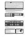
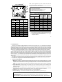
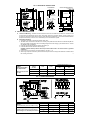
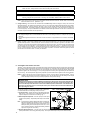
1
KBIC®
Solid State SCR
DC Motor Speed
Controls
®
See table 2 page 4 for KBIC
models covered by this manual
Patented Ultra Fast
CL Circuit Prevents
Demagnetization in
PM Motors
Installation and
Operating
Instructions
Basic KBIC
®
PATENTED
See SAFETY WARNING on page 4
*See Page 3
™
A COMPLETE LINE OF MOTOR DRIVES
©1996 KB ELECTRONICS, INC.
TABLE OF CONTENTS
Section
Page
i.
ii.
iii.
I.
II.
III.
IV.
V.
Safety Warning . . . . . . . . . . . . . . . . . . . . . . . . . . . . . . . . . . . . . . . . . . . . . . . . . . . . . . . . . . . . . . . . . . . . . . . . . . . . 3
Simplified Instructions . . . . . . . . . . . . . . . . . . . . . . . . . . . . . . . . . . . . . . . . . . . . . . . . . . . . . . . . . . . . . . . . . . . . . . . . 3
Introduction . . . . . . . . . . . . . . . . . . . . . . . . . . . . . . . . . . . . . . . . . . . . . . . . . . . . . . . . . . . . . . . . . . . . . . . . . . . . . . . 6
Application Information . . . . . . . . . . . . . . . . . . . . . . . . . . . . . . . . . . . . . . . . . . . . . . . . . . . . . . . . . . . . . . . . . . . . . . 6
Installation Instructions . . . . . . . . . . . . . . . . . . . . . . . . . . . . . . . . . . . . . . . . . . . . . . . . . . . . . . . . . . . . . . . . . . . . . . 7
Adjustments & Control Functions . . . . . . . . . . . . . . . . . . . . . . . . . . . . . . . . . . . . . . . . . . . . . . . . . . . . . . . . . . . . . 10
Switching Circuits . . . . . . . . . . . . . . . . . . . . . . . . . . . . . . . . . . . . . . . . . . . . . . . . . . . . . . . . . . . . . . . . . . . . . . . . . 11
Limited Warranty . . . . . . . . . . . . . . . . . . . . . . . . . . . . . . . . . . . . . . . . . . . . . . . . . . . . . . . . . . . . . . . . . . . . . . . . . . 16
1.
2.
3.
4.
5.
6.
7.
8.
Nominal Trimpot Settings . . . . . . . . . . . . . . . . . . . . . . . . . . . . . . . . . . . . . . . . . . . . . . . . . . . . . . . . . . . . . . . . . . . . 3
Electrical Ratings . . . . . . . . . . . . . . . . . . . . . . . . . . . . . . . . . . . . . . . . . . . . . . . . . . . . . . . . . . . . . . . . . . . . . . . . . . . 4
General Performance Specifications . . . . . . . . . . . . . . . . . . . . . . . . . . . . . . . . . . . . . . . . . . . . . . . . . . . . . . . . . . . 4
Fuse Selection Chart . . . . . . . . . . . . . . . . . . . . . . . . . . . . . . . . . . . . . . . . . . . . . . . . . . . . . . . . . . . . . . . . . . . . . . . 5
Plug-in Horsepower Resistor® Chart . . . . . . . . . . . . . . . . . . . . . . . . . . . . . . . . . . . . . . . . . . . . . . . . . . . . . . . . . . . 5
Minimum Supply Wire Requirements . . . . . . . . . . . . . . . . . . . . . . . . . . . . . . . . . . . . . . . . . . . . . . . . . . . . . . . . . . . 8
Field Connections . . . . . . . . . . . . . . . . . . . . . . . . . . . . . . . . . . . . . . . . . . . . . . . . . . . . . . . . . . . . . . . . . . . . . . . . . . 8
Parts List . . . . . . . . . . . . . . . . . . . . . . . . . . . . . . . . . . . . . . . . . . . . . . . . . . . . . . . . . . . . . . . . . . . . . . . . . . . . . . . . 15
TABLES
FIGURES
1.
2.
3.
4.
5a.
5b.
5c.
6.
2
®
Basic KBIC . . . . . . . . . . . . . . . . . . . . . . . . . . . . . . . . . . . . . . . . . . . . . . . . . . . . . . . . . . . . . . . . . . . . . . . . . . . . . .
Mechanical Specifications . . . . . . . . . . . . . . . . . . . . . . . . . . . . . . . . . . . . . . . . . . . . . . . . . . . . . . . . . . . . . . . . . . .
Connection Diagrams . . . . . . . . . . . . . . . . . . . . . . . . . . . . . . . . . . . . . . . . . . . . . . . . . . . . . . . . . . . . . . . . . . . . . . .
ACCEL Trimpot Adjustment . . . . . . . . . . . . . . . . . . . . . . . . . . . . . . . . . . . . . . . . . . . . . . . . . . . . . . . . . . . . . . . . .
Master/Slave Circuit . . . . . . . . . . . . . . . . . . . . . . . . . . . . . . . . . . . . . . . . . . . . . . . . . . . . . . . . . . . . . . . . . . . . . . .
Dynamic Brake Circuit . . . . . . . . . . . . . . . . . . . . . . . . . . . . . . . . . . . . . . . . . . . . . . . . . . . . . . . . . . . . . . . . . . . . .
Overload Protection . . . . . . . . . . . . . . . . . . . . . . . . . . . . . . . . . . . . . . . . . . . . . . . . . . . . . . . . . . . . . . . . . . . . . . .
Schematic . . . . . . . . . . . . . . . . . . . . . . . . . . . . . . . . . . . . . . . . . . . . . . . . . . . . . . . . . . . . . . . . . . . . . . . . . . . . . . .
5
7
8
10
12
13
13
14
i. SAFETY WARNING!
This product should be installed and serviced by a qualified technician, electrician or electrical maintenance person familiar
with its operation and the hazards involved. Proper installation, which includes wiring, mounting in proper enclosure, fusing or
other overcurrent protection and grounding, can reduce the chance of electric shocks, fires or explosion in this product or
products used with this product, such as electric motors, switches, coils, solenoids and/or relays. Eye protection must be worn
and insulated adjustment tools must be used when working with control under power. This product is constructed of materials
(plastics, metals, carbon, silicon, etc.) which may be a potential hazard. Proper shielding, grounding and filtering of this product
can reduce the emission of radio frequency interference (RFI) which may adversely affect sensitive electronic equipment. If
information is required on this product, contact our factory. It is the responsibility of the equipment manufacturer and individual
installer to supply this safety warning to the ultimate user of this product. (SW effective 11/92)
This control contains electronic Start/Stop and Inhibit circuits which can be used to start and stop the control. However,
these circuits are never to be used as safety disconnects since they are not fail-safe. Use only the AC line for this purpose.
The input circuits of this control (potentiometer, Inhibit) are not isolated from AC line. Be sure to follow all instructions
carefully. Fire and/or electrocution can result due to improper use of this product.
This product complies with all CE directives pertinent at the time of manufacture. Contact factory for detailed
installation instructions and Declaration of Conformity.
ii. SIMPLIFIED INSTRUCTIONS – Read these simplified instructions before operating control. (See Safety Warning.)
1. Be sure input AC line voltage corresponds to control voltage. (See Electrical Rating chart, table 2 p. 4.)
2. Install the correct Plug-in Horsepower Resistor® according to armature voltage and motor horsepower (See chart, p. 5).
3. Recheck connections: AC line to L1 and L2, armature to A+ and A- and Field (Shunt motors only) to F+ and F-. (Note: if
motor runs in improper direction, interchange armature leads.)
4. Nominal trimpot settings are as follows (expressed in % of full CW rotation):
5. It is recommended that both AC line and armature fuses should be installed in this product. (See sec. IID, p. 9.)
TABLE 1 – NOMINAL TRIMPOT SETTINGS (For detailed instruction see Sec. III)
MIN (minimum speed)
15%
CL (current limit/torque)
50%
MAX (maximum speed)
60%
ACCEL (acceleration start)
50%
IR (IR Compensation)
25%
3
TABLE 2 – ELECTRICAL RATINGS
AC Line
Voltage
(VAC) ± 15%
50/60Hz
Model
Number
RATING WITHOUT AUXILIARY HEATSINK
Motor
Voltage
3
(VDC)
Max. AC
Load Current
(RMS Amps)
Max. DC
Load Current
(Avg. Amps)
RATING WITH AUXILIARY HEATSINK
MAX
HP
Max. AC
Load Current
(RMS Amps)
Max. DC
Load Current
(Avg. Amps)
MAX
HP
FIELD VOLTAGE
(Shunt wound
Motor Only)
(VDC)
50, 100
KBIC-120
115
0 - 90
9.0
6.0
0.5
18.0
12.0
1
KBIC-125
115
0 - 90
12.0
8.0
0.75
24.0
16.0
1.5
50, 100
KBIC-240
230
0 - 180
9.0
6.0
1
18.0
12.0
2
100, 200
230
0 - 180
12.0
8.0
1.5
24.0
16.0
3
100, 200
115
0 - 90
230
0 - 180
115 / 230
0 - 90
KBIC-225
1
KBIC-240D
KBIC-240DS2
9.0
6.0
0.5
18.0
12.0
1
9.0
6.0
0.5
18.0
12.0
1
50, 100
2
100, 200
1
100
Notes:
(1) Model KBIC-240D is designed to accept 115 or 230 VAC line input to provide 0 - 130 VDC with a 115 or 230 VAC line and 0 - 220 VDC
with a 230 VAC line.
(2) Model KBIC-240DS is designed to accept 115 or 230 VAC line input to provide 0-130 VDC with a 115 or 230 VAC line. (Also see
Information Sheet A40058)
(3) A higher output voltage can be reached by increasing MAX trimpot setting.
TABLE 3 – GENERAL PERFORMANCE SPECIFICATIONS
Speed Range (ratio) . . . . . . . . . . . . . . . . . . . . . . . . . . . . . . . . . . . . . . 50:1
Load Regulation (% base speed) (0 - full load; 50:1 speed range) . . . . 1*
Line Voltage Regulation (% base speed at full load; 100 - 130 VAC) . 1/2*
Control Linearity (% speed vs. dial rotation) . . . . . . . . . . . . . . . . . . . . . . 2
CL/Torque Range (% full load) . . . . . . . . . . . . . . . . . . . . . . . . . . . . 0 - 300
ACCEL Time Period (0 - full speed) (secs) . . . . . . . . . . . . . . . . . 0.5 - 4.0
MIN Speed Trimpot Range (% full speed) . . . . . . . . . . . . . . . . . . . 0 - 30*
MAX Speed Trimpot Range (% full speed) . . . . . . . . . . . . . . . . . 50 - 110*
IR Compensation Trimpot Range (at specified full load) (volts) . . . . 0 - 24
Maximum Allowable Ambient Temperature at full rating (º C/º F) . . 45/113
Maximum Inrush Start Current (Peak DC amps) . . . . . 3 times CL Setting
PLUG-IN HORSEPOWER RESISTOR®
A Plug-in Horsepower
Resistor ® must be
installed to match the
KBIC® to the motor
horsepower and voltage.
See table 4, p. 5 for the
correct value. Plug-in
®
Horsepower Resistors
are stocked by your
distributor.
CAUTION
Be sure Plug-in
Horsepower
Resistor® is
inserted completely
into mating socket.
*Performance is for SCR rated PM motors only. Lower performance can be expected with other motor types. Factory setting is for 3% load
regulation. To obtain superior regulation, see sec. III E, p. 11.
4
FIG. 1 – BASIC KBIC®
*Note: Specific applications may require a different fuse value than
indicated. This is based on several factors such as ambient temperatures,
duty cycle, motor form factor and CL setpoint.
(1)
(2)
(3)
(4)
FIG. 1 – FEATURES AND FUNCTIONS
Plug-in Horsepower Resistor®
Mounting Holes for Armature and AC Line Fuses
Trimpots: MIN, MAX, ACCEL, IR & CL
Auxiliary Heatsink (optional) (see fig. 2, p. 7)
TABLE 5 – PLUG-IN HORSEPOWER RESISTOR® CHART(1)
Motor Horsepower(2)
Approx.
Motor
Armature Voltage Armature Voltage Current
(DC Amps)
90VDC
180VDC
TABLE 4. FUSE SELECTION CHART*
90 VDC Motor 180 VDC Motor
HORSEPOWER
Approx.
Motor Current
(DC Amps)
Fuse Rating
(AC Amps)
Plug-in
Horsepower
Resistor
Value (Ohm)
Individual
Plug-in
Horsepower
Resistor® P/N
1/100
1/50
0.1
1.0
9833
1/50
1/25
0.2
0.51
9834
1/30, 1/25
1/15
0.35
0.35
9835
1/10
0.5
0.25
9836
1/100
1/50
0.1
2/10
1/20
1/50
1/25
0.2
3/10
1/15, 1/12
1/6
0.8
0.18
9837
1/30
1/15
0.3
1/2
1/10, 1/8, 1/6
1/4
1.3
0.1
9838
1/20
1/10
0.5
3/4
1/4
1/2
2.5
0.05
9839
1/15
1/8
0.7
1
1/3
3/4
3.3
0.035
9840
1/2
1
5.0
0.025
9841
7.5
0.015
9842
2
10.0
0.01
9843
3
15.0
0.006
9850
1/10
1/5
1.0
1/8
1/4
1.3
2
3/4
1/6
1/3
1.7
3
1
1/4
1/2
2.5
4
1/3
3/4
3.3
5
1
5.0
8
7.5
12
2
10.0
15
3
15.0
25
1/2
3/4
1
1
1
1
1
1
Notes:
(1) Motor horsepower and armature voltage must be specified in order
to select correct Plug-in Horsepower Resistor®.
(2) For motor horsepower not indicated use lower value Plug-in
Horsepower Resistor®.
5
iii. INTRODUCTION
®
Thank you for purchasing the KBIC "Standard of the Industry" DC motor speed control. They are designed for applications
demanding good performance, high reliability and low cost. The controls are fabricated with components that have proven reliability,
including MOV transient protection, which is used to protect the power bridge. Integrated circuitry is used to provide an uncomplicated
design with superior load and line voltage regulation. The patented Direct-Fed™ current limit circuit protects the motor and control
against overloads by limiting the maximum level of output current. It also prevents motor failure due to demagnetization of the magnets
of PM motors. Acceleration start (adjustable from 0.5 to 4 seconds) provides a smooth start each time the AC power is applied.
®
®
A unique feature of the KBIC control is the Plug-in Horsepower Resistor . It eliminates the need to recalibrate IR Comp. and CL
when the control is used over a wide range of motor horsepower. Additional versatility is achieved by using the Auxiliary Heatsink
(optional) which is used to double the horsepower rating of each model. The output of the control is a linear function of potentiometer
®
rotation. The KBIC can also be operated in a voltage following mode by supplying an isolated analog signal (0-7 VDC) to the input
terminals P2(+) and F-. If an isolated input signal is not available, the optional Barrier Terminal Board Signal Isolator (SI-5) can be used.
The controls are terminated as standard with Q-D terminals. A Barrier Terminal Board is available which incorporates both line and
armature fuses.
The Inhibit™ circuit (Terminals I1 and I2) is provided to electronically disconnect the armature output voltage. Another standard
®
feature is Auto Inhibit. This circuit prevents false starts and high surge currents when cycling the KBIC control with the AC line.
All models are UL Recognized for the USA and Canada and CE approved.
I.
APPLICATION INFORMATION
®
A. Motor Type – The KBIC is designed for Permanent Magnet (PM), Shunt Wound and Universal (AC/DC) motors. Controls
operated on 115 volt AC inputs are designed for 90 volt SCR rated motors. Controls operated on 230 volt AC inputs are
designed for 180 volt SCR rated motors. Use of higher voltage motors will result in reduction of available MAX speed. Also,
if motor is not an SCR rated type, the actual AC line amperage at full load should not exceed the motor's DC nameplate
rating.
B. Torque Requirements – When replacing an AC induction motor with a DC motor and speed control, consideration must
be given to the maximum torque requirements. The full load torque rating of the DC motor must be equal to, or greater than,
that of the AC motor.
®
C. Acceleration Start – The KBIC contains an adjustable acceleration start feature which allows the motor to smoothly
accelerate from 0-full speed over a time period of 0.5-4 seconds. The "ACCEL" is factory set at 2 seconds.
®
D. Limitation in Use – The KBIC controls are designed for use on machine applications.
E. Armature Switching – Do not switch the armature without taking proper precautions. (See sec. IV, p. 11)
CAUTION
Consult factory before using on constant horsepower applications such as saws or drill presses. Do not use in
explosive atmosphere.
®
Be sure the KBIC is used within its maximum ratings. Follow all installation instructions carefully. (Refer to section II.)
6
FIG. 2 – MECHANICAL SPECIFICATIONS
POTENTIOMETER
3/8
OPTIONAL AUXILIARY HEATSINK
0.982
1/2
0.500
CONTROL
1/4" ROUND
ALUM. SHAFT
5.625
7.000
3/8-32
ANTIBUSHING
ROTATION
PIN
3.110
5.625
6.250
0.125
3
1
1.250
2
.438
1.375
DWG #:D2600-1-00281
II. INSTALLATION INSTRUCTIONS
A.
Location and Mounting – The KBIC® controls should be mounted on a flat surface and located in an area where it will
not be exposed to contaminants such as water, metal chips, solvents or excessive vibration. When mounting in an
enclosure, the air space should be large enough to provide adequate heat dissipation. The maximum allowable ambient
temperature at full rating is 45 ºC/113 ºF. Consult factory if more information is required.
B.
Initial Setup and Wiring.
1. Install proper size Plug-in Horsepower Resistor® (See chart).
2. The KBIC can be connected to a standard 115V or 230V (±15%) 50/60 Hz AC line based on model selected [Be sure
the AC input voltage corresponds to the control voltage rating and the motor rating (e.g. 90-130VDC motor on 115VAC
and 180VDC motor on 230VAC)].
3. Follow the recommended supply wire sizes as per table 6, p. 8.
4. Follow the NEC and other electrical codes that apply.
CAUTION: Separate branch protection must be provided on 240V circuits. Do not fuse neutral or grounded
conductors.
5. Connect control in accordance to connection diagram - See fig. 3, p. 8.
6. When using a step-down transformer (440 VAC to 220 VAC) be sure the VA rating of the transformer is at least 3 times
the VA rating of the motor.
7
TABLE 6
Minimum Supply Wire
Size Requirements
*Minimum Recommended
Wire Size
MINIMUM WIRE SIZE (AWG) Cu only
MAX. MOTOR
CURRENT
(DC AMPS)
MAX. MOTOR
HP 90V
MAX. MOTOR
HP 180V
MAX. 50 FOOT
RUN
MAX. 100 FOOT
RUN
6
0.5
1
16
14
12
1
2
14
12*
16
1.5
3
12
12
FIG. 3 – CONNECTION DIAGRAM
TABLE 7
Field Connections (Shunt-wound Motors Only)
Caution: Shunt-wound motors may be
damaged if field remains energized without
motor rotating for an extended period of time.
8
AC LINE VOLTAGE
FIELD VOLTAGE (VDC)
FIELD CONNECTION
115
100
F+, F-
FIELD TYPE
Full Voltage
115
50
F+, L1
Half Voltage
230
200
F+, F-
Full Voltage
230
100
F+, L1
Half Voltage
WARNING: If control is wired to a transformer, do not switch the primary side of transformer to disconnect power or catastrophic
failure can result. Always disconnect control from secondary side of transformer.
CAUTION: Do not bundle potentiometer connections (P1, P2, P3) and Inhibit™ connections (I1, I2) with AC line or motor wires.
WARNING: Armature Switching. Do not switch the armature in and out of circuit or catastrophic failure will result. If armature
switching is required for dynamic brake or reversing, use model KBRG, KBPB or KBCC-R suffix controls.
NOTE: (Shunt motors only) For 90V DC motors with 50VDC fields and 180VDC motors with 100VDC fields, use half voltage
field connections F+ and L1. (See table 7, p. 8)
C. Voltage Following – All models can be controlled with an isolated analog reference voltage (0-7 VDC) in lieu of the main
speed potentiometer. The voltage is connected to P2 (+) and F-. The control output voltage will linearly follow the input voltage.
The source impedance of the input should be 10K ohms or less. The Min and Max trimpots are rendered inoperative in the
voltage following mode. Use auxiliary trimpots for scaling and to limit the control range. If the input signal is not isolated, or
is a current signal (4 - 20 mA), the KBSI-240D or SI-5 Barrier Terminal Board Signal Isolator must be used. It will allow direct
connection to process controllers and microprocessors.
CAUTION:
1. The voltage feeding P2 and F- must be isolated from the AC line. Do not earth ground P2 or F- to setup a zero or ground
reference.
2. Do not bundle signal wires to P2 and F- with AC line or motor connections. If signal wires are over 18 inches, use shielded
cables.
D. Fusing – The KBIC® has provision for adding a built-in AC line fuse and armature fuse*. The AC line fuse protects the control
against catastrophic failure. If the fuse blows, the control is miswired, the motor is shorted or grounded, or the KBIC® control
is defective. The armature fuse provides overload protection for the motor and control. Choose the proper size armature fuse
and AC line fuse (see fuse chart table 4, p. 5) by multiplying the maximum DC motor amps by 1.7. Armature and AC line fuse
kits are available from your distributor. On domestic 230 Volt AC lines, separate branch circuit protection for each line must
be used. All fuses should be normal blow ceramic 3AG or MDA or equivalent. The Barrier Terminal Kit (optional) contains
prewired AC line and armature fuses. *Contact your distributor.
9
III. ADJUSTMENTS AND CONTROL FUNCTIONS
®
The KBIC is factory adjusted to provide 0 to full speed range using a 5K potentiometer. Minimum and maximum speed trimpots
are provided to change the speed range from other than 0 to full speed. An acceleration start (located directly behind the MIN
trimpot) is factory set to provide motor acceleration from 0 to full speed over a time period of 2 seconds (approx.) each time the
AC power is applied. The current limiting (CL, or torque output) adjustment is factory set to approximately one and a half times
the motor rating. The IR Compensation (IR) is factory adjusted to provide excellent motor regulation under normal operation.
NOTE: In order for the IR comp and CL trimpot settings to be correct, the proper Plug-in Horsepower Resistor® must be
installed for the particular motor and input voltage being used. Do not attempt to change the settings of the trimpots
unless absolutely necessary since they are factory adjusted to near optimum settings.
IMPORTANT NOTE:
Readjusting the ACCEL time will affect the MAX speed and IR Comp. settings which will have to be readjusted (see
this Section). If the ACCEL time is decreased to the minimum time of 0.5 seconds (6 o'clock trimpot position), then
increase the IR trimpot 25% CW rotation and decrease the MAX trimpot 20% CCW rotation. If the ACCEL time is
increased to the maximum time of 4 seconds (full rotation), then decrease the IR and increase the MAX as per
above percentages of rotation.
The following procedure is presented in required order of adjustment.
It should be followed when readjusting all trimpot functions:
FIG. 4 – ACCEL TRIMPOT ADJUSTMENT
A. Acceleration Start – (ACCEL trimpot is located directly behind the
MIN trimpot.) If the ACCEL is to be readjusted to different times,
adjust the trimpot to the desired time according to fig. 4.
B. Maximum Speed Adjustment – Set main speed pot to full speed
(maximum CW position). Adjust MAX speed trimpot to new desired
setting.
Note:
Do not attempt to adjust the MAX speed above the rated motor
RPM since unstable motor operation may occur. For moderate
changes in the MAX speed, there will be a slight effect on the
MIN speed setting when the MIN speed is set at zero. There
may be significant variation in the MIN speed setting if the MIN
speed is at a higher than zero setting.
C. Minimum Speed Adjustment – If a higher than zero speed is desired, readjust the minimum speed by turning the main
speed potentiometer to zero setting (full CCW position). Then adjust the MIN speed trimpot to the desired setting.
10
Note:
The MIN speed adjustment will affect the MAX speed setting. Therefore, it is necessary to readjust the MAX speed after
the MIN speed, and it may be necessary to repeat the sequence until both the MIN and the MAX speeds are set to the
desired levels.
D. Current Limit (CL/Torque Adjustment) – CL circuitry is provided to protect the motor and control against overloads. The
CL also limits the inrush current to a safe level during startup. The CL is factory set to approximately 1.5 times the full load
rating of the motor. (CL trimpot is nominally set to approx. 50% of full CW rotation.)
Note:
The correct value Plug-in Horsepower Resistor® must be installed in order for the CL and IR comp. to operate properly.
Calibration of the CL & IR comp. is normally not required when the proper Plug-in Horsepower Resistor ® is
installed.
To set the CL to factory specifications adjust as follows:
1. Set main speed potentiometer at approximately 30 - 50% CW rotation. Set CL trimpot to full CCW position.
2. Connect a DC ammeter in series with the armature lead.
3. Lock shaft of motor (be sure CL pot is in full CCW position). Apply power and rotate CL pot CW slowly until DC ammeter
reads 1.5 times motor rating (do not exceed 2 times motor rating). Note: Complete this step within 5 seconds to avoid
damaging motor.
Note:
If only an AC ammeter is available, it can be installed in series with AC input line. Follow above instructions; however,
set AC amperage at 0.75 times motor rating.
E. IR Compensation Adjustment – IR compensation is provided to substantially improve load regulation. If the load presented
to the motor does not vary substantially, the IR adjustment may be set at a minimum level (approximately 1/4 of full setting).
The control is factory adjusted to approximately 3% regulation. If superior performance is desired (less than 1% speed
change of base speed from 0 to full load), then the IR comp. should be adjusted as follows:
Note: Excessive IR comp. will cause control to become unstable, which causes motor cogging.
1. Set IR comp. trimpot at approximately 25% of CW rotation. Run motor unloaded at approximately 1/3 speed and record
RPM.
2. Run motor with maximum load and adjust IR comp. trimpot so that the motor speed under load equals the unloaded speed
per step 1.
3. Remove load and recheck unloaded RPM. If unload RPM has shifted, repeat procedure for more exact regulation. The
control is now compensated to provide minimal speed change under large variations of applied load.
IV. SWITCHING CIRCUITS
A. AC Line Switching – The KBIC® can be safely turned "on" and "off" rapidly using the AC Line (no waiting time is required).
Auto Inhibit® circuitry contained in the KBIC® automatically resets critical components each time the AC line is interrupted.
This, along with Acceleration Start and CL, will provide a smooth start each time the AC line is connected.
11
Warning: Do not disconnect and reconnect the Armature with the AC line applied or catastrophic failure will result.
B. Armature Switching – If the armature is to be disconnected and reconnected with AC power applied, the Inhibit Circuit™ must
be simultaneously activated and deactivated. Connect I1 and I2 together to activate the Inhibit Circuit™. See fig. 5B for
dynamic brake circuit.
®
C. Reversing and Dynamic Braking – KB has developed the APRM * which provides anti-plug "instant" reversing and solid state
dynamic braking. The APRM® is built in as standard in all KBCC-R suffix models and in all KBPB™ models. *Patented.
FIG. 5 APPLICATIONS
A. Master/Slave Connections. The KBIC can be used with the KBSI to drive multiple motors:
(a)
(b)
From a single main potentiometer
From a single main motor.
FIG. 5A – MASTER SLAVE CIRCUIT
** connect high side of potentiometer
* A 10K ratio potentiometer is used to control up
to terminal “P” (” QD)
to (10) "slave" motors.
If a 5K ratio
potentiometer is used, up to (5) "slave" motors
can be controlled.
1) Multiple KBIC® controls should be powered
from the same phase AC line.
2) The positive output terminal to each speed
control must be installed with a 1A-600PIV
isolation diode.
12
FIG. 5B – DYNAMIC BRAKE CIRCUIT (Using Inhibit™)
Notes (Dynamic Brake Circuit)
* Choose RB resistance and wattage according to
braking requirements.
** Inhibit™ circuit extinguishes output of control during
brake. When the armature is reenergized, the Inhibit™
releases which allows for a smooth start.
C. Overload Protection with KBAP-240D (P/N 9106) (Optional)
The KBAP-240D is a multipurpose DC Current Sensing Relay and Overload Protector. It is specifically designed for
use with DC motors and speed controls from 1/8 - 3 HP. KBAP-240D operates by sensing current in the armature
circuit. When the preset level is reached, the output relay (RY1) trips. An adjustable time delay (0.2 - 15 secs.) is
incorporated, which eliminates nuisance tripping. Manual or automatic reset is provided at the user's option along
with a LED, which indicates when the preset current level has been reached. When an overload occurs, the KBAP240D can be used to shut the system down, sound an alarm, or initiate corrective action before damage occurs.
Internal Sensing. Wire the KBAP in accordance with the following wiring diagram.
13
V. – LIMITED WARRANTY - KBIC®
For a period of 18 months from date of original purchase, KB will repair or replace without charge devices which our
examination proves to be defective in material or workmanship. This warranty is valid if the unit has not been
tampered with by unauthorized persons, misused, abused, or improperly installed and has been used in accordance
with the instructions and/or ratings supplied. The foregoing is in lieu of any other warranty or guarantee, expressed
or implied, and we are not responsible for any expense, including installation and removal, inconvenience, or
consequential damage, including injury to any person, caused by items of our manufacture or sale. Some states do
not allow certain exclusions or limitations found in this warranty so that they may not apply to you. In any event, KB's
total liability, under all circumstances, shall not exceed the full purchase price of this unit. (rev 4/88)
The information contained in this brochure is intended to be accurate. However, the manufacturer retains the right to make changes in design
which may not be included herein.
KB ELECTRONICS, Inc.
12095 NW 39th Street, Coral Springs, FL 33065 • (954) 346-4900 • Fax (954) 346-3377
Outside Florida Call TOLL FREE (800) 221-6570
A40202