1
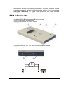
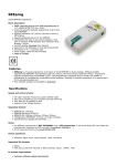
864
42
Introduction
864 is a universal programmer that supports programmable
integrated circuits or devices manufactured in various
technologies. Powerful internal pin-driver electronics controls
logic levels, pull-up/pull-down, clock, ground, one power supply
and two programming supplies and is able to read all 48 pins
independently. This advanced design gives 864 the ability to
handle almost every programmable device in DIL package up
to 48 pins without any adapters and/or family modules. This
design philosophy allows B+K PRECISION to easily add new
devices to the device list, giving you the freedom to implement
the optimum device in your designs.
864 is also a tester of TTL/CMOS logic circuits and various
memories. Furthermore, it can generate user-definable test
pattern sequences. 864 is a true universal and a true low-cost
programmer, providing the best "value for money" in today's
market.
864 works with the IBM PC Pentium compatible or higher,
portable or desktop personal computers. No special interface
card is required to connect to the PC since 864 uses the
standard parallel printer port. The 864 control program also
supports bi-directional protocols for the parallel connection to
the PC printer port providing fast and reliable communication
speed.
The programmer has on-board intelligence and is controlled by
powerful Microcontroller system and support devices. 864 has
been designed for multitasking operating systems and is
able to perform time-critical programming sequences
independently of the PC operating system status and without
being interrupted by any other parallel process running on the
PC. Consequently, 864 works without any problem on systems
running Windows 95/98/Me/NT/2000/XP.
864 performs device insertion test (wrong or backward
position) and contact check (poor contact pin-to-socket) before
it programs any device. These capabilities, supported by
current limit protection and signature-byte check, help prevent
chip damage due to operator error.
Built-in protection circuits help prevent damage of the target
device due to mains supply fluctuations, communication errors
or if the PC operating system fails. In the event of such errors
the 864 performs independently of the PC exactly specified
special sequences so that the target device remains intact. 864
performs self test (diagnostic tests), including verification of
pin-driver voltage/level, for accurate timing of the signals
43
applied to the target device and for reliable communication with
the PC.
864 incorporates optimal PCB design criteria to minimize
unwanted effects at the pins of the target socket (such as
ground-bouncing and supply/programming voltage glitches). All
the inputs of the 864, including the socket, are protected
against ESD and whilst inserted the target device is also
protected against ESD damage.
864 performs programming verification at the marginal level
of supply voltage, which, obviously, improves programming
yield and guarantees long data retention.
Various socket converters are available to handle device in
PLCC, SOIC, PSOP, SSOP, TSOP, TSSOP, TQFP, QFN
(MLF), SDIP, BGA and other packages.
864 programmer is driven by an easy-to-use control program
with pull-down menu, hot keys and on-line help. Selecting of
device is performed by its class, by manufacturer or simply by
typing a fragment of vendor name and/or part number.
Standard device-related commands (read, blank check,
program, verify, erase) are boosted by some test functions
(insertion test, signature-byte check), and some special
functions (autoincrement, production mode - start immediately
after insertion of chip into socket).
All known data formats are supported. Automatic file format
detection and conversion during load of file.
The rich-featured autoincrement function enables to assign
individual serial numbers to each programmed device - or
simply increments a serial number, or the function enables to
read serial numbers or any programmed device identification
signatures from a file.
The software also provides a many informations about
programmed device. As a special, the drawing of all available
packages are provided. The software provide also explanation
of chip labeling (the meaning of prefixes and suffixes at the
chips) for each supported chip.
It is important to remember that in most cases new devices
require only a software upgrade since the 864 has 48 true
pin drivers, which can perform as required under program
control. With our prompt service new devices can be added to
the current list within hours!
44
Advanced design, including protection circuits, original brand
components and careful manufacturing allows us to provide a
one-year warranty on parts and labor for the 864 (limited
25,000-cycle warranty on ZIF socket).
864 elements
48 pin ZIF (Zero Insertion Force) socket
LED indicator power/sleep
LED indicators for work result
YES! Button
Connector for PC <-> 864 communication cable
Power supply connector
Power supply connector
45
Note: Due to low power consumption of 864 in inactive state, it
doesn't require power switch. When the power LED indicator
glows with a low intensity the 864 is in inactive mode.
Connecting 864 to the PC
Switch off PC and programmer. Insert the communication
cable included with your 864 programmer package to a free
printer port on your PC. If your computer is equipped with only
one printer port, substitute the programmer cable for the printer
cable. Connect the opposite cable end to the programmer.
Screw on both connectors to counter-connectors. This is very
important. It may be uncomfortable to switch between printer
cable and programmer cable, though it is not recommended to
operate the 864 programmer through a mechanical printer
switch. Use of an electronic printer switch is impossible. But
you can install a second multi-I/O in your computer, thus
obtaining a supplementary printer port, says LPT2. So your
printer may remain on LPT1 while the programmer on LPT2.
Switch on the PC.
Connect the mains connector of the power supply (or the wallplug power supply itself) to a mains plug, then connect the
mini-DIN connector to the programmer's connector labeled
"12VAC". At this time all 'work result' LEDs (and 'POWER'
LED) light up successive and then switch off. Once the
POWER LED lights with low brightness then the 864
programmer is ready to run.
Next run the control program for 864.
Note: When the PC is switch off and you turn on programmer,
LED maybe not blinking, before programmer maybe
permanent on reset.
Caution! If you don't want to switch off your PC when
connecting the 864, proceed as follows:
• When connecting the programmer to the PC: FIRST insert
the communications cable and THEN the power-supply
connector.
• When disconnecting the programmer from the PC: FIRST
disconnect the power-supply connector and THEN the
communication cable.
From 864's point of view the connecting and disconnecting
sequence is irrelevant. Protection circuits on all programmer
inputs keep it safe. But think of your PC please.
46
Problems related to the 864
interconnection, and their removing
If you have any problems with 864
see section Common notes please.
PC
PC interconnection,
Manipulation with the programmed
device
After selection of desired device for your work, you can insert
into the open ZIF socket (the lever is up) and close socket (the
lever is down). The correct orientation of the programmed
device in ZIF socket is shown on the picture near ZIF socket
on the programmer's cover. The programmed device is
necessary to insert into the socket also to remove from the
socket when LED BUSY light off.
Note: Programmer's protection electronics protect the target
device and the programmer itself against either short or longterm power failures and, partly, also against a PC failure.
However, it is not possible to grant the integrity of the target
device due to incorrect, user-selected programming
parameters. Target device may be not destroyed by forced
interruption of the control program (reset or switch-off PC), by
removing the physical connection to the programmer, but the
content of actually programmed cell may remains undefined.
Don't unplug the target device from the ZIF socket during work
with devices (LED BUSY shine).
Self test and Calibration
If you feel that your programmer does not react according to
your expectation, please run the programmer self test using
Diagnostic POD, enclosed with the standard delivery package.
For optimal results with programmer we recommend you
undertake every 6 months, an extended test and to check the
calibration. See instructions for self test in the Diagnostics
menu of PG4UW.
47
Technical specification
HARDWARE
Socket, pin drivers and DACs
• 48-pin DIL ZIF (Zero Insertion Force) socket accepts both
300/600 mil devices up to 48-pin
• Three D/A converters for VCCP, VPP1, and VPP2, with
controllable rise and fall time and current limitation
• TTL driver provides H, L, CLK, pull-up, pull-down, or tri-state
on all 48 pins
• full support of Low Voltage circuits from 1.8 V up
• autocalibration
DEVICE SUPPORT
Programmer
• EPROM: NMOS/CMOS, 1702*, 2708*, 27xxx and 27Cxxx
series, with 8/16 bit data width, full support for LV series
• EEPROM: NMOS/CMOS, 28xxx, 28Cxxx, 27EExxx series,
with 8/16 bit data width
• Flash EPROM: 28Fxxx, 29Cxxx, 29Fxxx, 29BVxxx, 29LVxxx,
29Wxxx, 49Fxxx series, from 256Kbit to 32Mbit, with 8/16 bit
data width, full support for LV series
• Serial E(E)PROM: 24Cxxx, 24Fxxx, 25Cxxx, 45Dxxx,
59Cxxx, 25Fxxx, 25Pxxx, 85xxx, 93Cxxx, NVM3060, MDAxxx
series, full support for LV series
• Configuration (EE)PROM: XCFxxx, XC17xxxx, XC18Vxxx,
EPCxxx, AT17xxx, 37LVxx
• PROM: AMD, Harris, National, Philips, Signetics, Tesla, TI
• NV RAM: Dallas DSxxx, SGS/Inmos MKxxx, SIMTEK
STKxxx, XICOR 2xxx, ZMD U63x series
• PLD: Altera: MAX 3000A, MAX 7000A, MAX 7000B, MAX
7000S, MAX7000AE
• PLD: Lattice: ispGAL22V10x, ispLSI1xxx, ispLSI1xxxEA,
ispLSI2xxx,
ispLSI2xxxA,
ispLSI2xxxE,
ispLSI2xxxV,
ispLSI2xxxVE, M4-xx/xx, M4A3-xx/xx, M4A5-xx/xx, M4LVxx/xx
• PLD: Xilinx: XC9500, XC9500XL, XC9500XV, CoolRunner
XPLA3, CoolRunner-II
• other PLD: SPLD/CPLD series: AMI, Atmel, AMD-Vantis,
Gould, Cypress, ICT, Lattice, NS, Philips, STM, VLSI, TI
• Microcontrollers 48 series: 87x41, 87x42, 87x48, 87x49,
87x50 series
• Microcontrollers 51 series: 87xx, 87Cxxx, 87LVxx, 89Cxxx,
89Sxxx, 89LVxxx, all manufacturers, Philips 87C748..752
48
series, Philips LPC series, Cygnal/Silicon Laborat. C8051
series
• Microcontrollers
Intel
196
series:
87C196
KB/KC/KD/KT/KR/...
• Microcontrollers Atmel AVR: AT90Sxxxx, ATtiny series
• Microcontrollers ELAN: EM78Pxxx
• Microcontrollers Microchip PICmicro: PIC10xxx, PIC12Cxxx,
PIC16C5x, PIC16Cxxx, PIC17Cxxx, PIC18Cxxx, dsPIC
series
• Microcontrollers Motorola: 68HC11 series (1)
• Microcontrollers National: COP8xxx series
• Microcontrollers NEC: uPD78Pxxx series
• Microcontrollers Scenix (Ubicom): SXxxx series
• Microcontrollers SGS-Thomson: ST6xx series
• Microcontrollers TI: MSP430 series
• Microcontrollers ZILOG: Z86xxx series
• Microcontrollers other: Cypress, EM Microelectronic, Fujitsu,
Goal Semiconductor, Princeton, Macronix, Winbond, Hitachi,
Holtek, Infineon(Siemens), NEC, Samsung, Toshiba, ...
Note:
• Devices marked * are obsolete, programming with additional
module
• For all supported devices see actual Device list
I.C. Tester
• TTL type: 54,74 S/LS/ALS/H/HC/HCT series
• CMOS type: 4000, 4500 series
• static RAM: 6116 .. 624000
• user definable test pattern generation
Package support
• package support includes DIP, PLCC, SOIC, PSOP, SSOP,
TSOP, TSSOP, TQFP, QFN (MLF), SDIP, BGA and other
• support all devices in DIP with default ZIF-48 socket
• support devices in non-DIP packages up to 48 pin with
universal adapter (optional accessory, to be ordered
separately)
• compatible with third-party adapters for non-DIP support
Programming speed
Device
27C010
AT29C040A
AM29F040
PIC16C67
Conditions:
Operation
programming and verify
programming and verify
programming and verify
programming and verify
Time
39 sec
75 sec
165 sec
30 sec
P4, 2,4GHz,ECP, Windows XP
49
SOFTWARE
• Algorithms: only manufacturer approved or certified
algorithms are used.
• Algorithm updates: software updates are available approx.
every 2 weeks, free of charge.
• Main features: revision history, session logging, on-line help,
device and algorithm information
Device operations
• standard:
• automatic ID-based selection of EPROM/Flash EPROM
• blank check
• read
• program
• verify
• erase
• configuration and security bit program
• illegal bit test
• checksum
• security
• insertion test
• contact check
• ID byte check
• special
• production mode (automatic start immediately after device
insertion)
• automatic device serial number incrementation
• statistics
• count-down
Buffer operations
• view/edit, find/replace
• fill/copy, move, byte swap, word/dword split
• checksum (byte, word)
• print
Supported file formats
• unformatted (raw) binary
• HEX: Intel, Intel EXT, Motorola S, MOS, Exormax, Tektronix,
ASCII-space-HEX
• POF (Altera), JEDEC (ver. 3.0.A), for example from ABEL,
CUPL, PALASM, TANGO PLD, OrCAD PLD, PLD Designer
ISDATA etc.
50
PC system requirements
See section Introduction/ PC requirements
GENERAL
• operating voltage 12..15V AC, max.1A or 15..18V DC, max.
1A
• power consumption - max. 12W in active, 1.5W inactive
• dimensions 275x157x47 mm (10.8x6.2x1.9 inch)
• weight (without external adapter) 1.5kg (3.3 lb)
• temperature 5°C ÷ 40°C (41°F ÷ 104°F)
• humidity 20%.80%, non condensing
Package included
• 864 programmer
• connection cable PC-programmer
• diagnostic POD for self test
• anti-dust cover to ZIF socket
• switching power adapter 100..240V AC/15V DC/1A
• user manual
• software
• registration card
• transport case
Additional services
• AlgOR
• free technical support (phone/fax/e-mail).
• free lifetime software update via Web site.
51