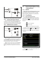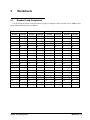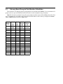
1
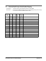
026-1711 Rev 2 06-29-09
Square D Smart Breaker
Panel Control Manual
1640 Airport Road, Suite 104
Kennesaw, GA 31044
Phone: (770) 425-2724
Fax: (770) 425-9319
ALL RIGHTS RESERVED.
The information contained in this manual has been carefully checked and is believed to be accurate. However, Computer Process Controls, Inc. assumes no responsibility for any inaccuracies that may be contained herein. In no event will
Computer Process Controls, Inc. be liable for any direct, indirect, special, incidental, or consequential damages resulting
from any defect or omission in this manual, even if advised of the possibility of such damages. In the interest of continued
product development, Computer Process Controls, Inc. reserves the right to make improvements to this manual, and the
products described herein, at any time without notice or obligation.
Table of Contents
1 OVERVIEW ................................................................................................................................................................... 1
1.1. THE SMART BREAKER SYSTEM ....................................................................................................................................
1.2. BREAKER NUMBERING ON THE SQUARE D MASTER AND SLAVE PANELS ..................................................................
1.2.1. Numbering Double and Triple Breakers...............................................................................................................
1.3. THE SQUARE D POWERLINK BREAKER PANEL ............................................................................................................
1.3.1. Compatible Square D Panels................................................................................................................................
1.3.2. Connection To Master Panel #0 (Master) ............................................................................................................
1.3.3. Networking Square D Master Panel to Square D Expansion Rails......................................................................
1.3.4. Expansion Panel Cable Maximum Length............................................................................................................
1.3.5. Network Panel Addressing....................................................................................................................................
1
1
2
3
3
3
4
4
5
2 E2 MODBUS DIRECT SUPPORT FOR SQUARE D BREAKER PANELS.......................................................... 6
2.1. NETWORK CONNECTION TO E2 ....................................................................................................................................
2.1.1. E2 Termination .....................................................................................................................................................
2.2. E2 SETUP OF SQUARE D BREAKER PANELS .................................................................................................................
2.2.1. Set Up Network Ports............................................................................................................................................
2.2.2. Add and Connect Square D Breaker Panels.........................................................................................................
2.3. SQUARE D APPLICATION SETUP IN E2: SINGLE BREAKER...........................................................................................
2.3.1. Adding Lighting Schedule Application .................................................................................................................
2.3.2. Light Outputs and Proof Inputs Setup...................................................................................................................
6
7
7
7
7
8
8
8
2.3.2.1. Light Outputs Setup ............................................................................................................................................................ 9
2.3.2.2. Proof Inputs Setup .............................................................................................................................................................. 9
2.4. SQUARE D APPLICATION SETUP IN E2: MULTIPLE BREAKER GROUPING .................................................................. 10
2.4.1. Setting Light Outputs .......................................................................................................................................... 10
2.4.2. Proof Inputs Setup for Multiple Breaker Grouping ............................................................................................ 11
3 SQUARE D SMART BREAKER GATEWAY BOARD ......................................................................................... 13
3.1. OVERVIEW ..................................................................................................................................................................
3.2. MOUNTING..................................................................................................................................................................
3.2.1. Environmental Specifications .............................................................................................................................
3.2.2. Square D Breaker Panel Mounting.....................................................................................................................
3.3. POWER WIRING ..........................................................................................................................................................
3.3.1. Square D Smart Breaker Gateway......................................................................................................................
3.4. NETWORKING .............................................................................................................................................................
3.4.1. Wiring the Square D Gateway to a Retail Solutions Site Controller (I/O Network) ..........................................
3.4.1.1.
3.4.1.2.
3.4.1.3.
3.4.1.4.
Wire Connection ...............................................................................................................................................................
Gateway Board I/O Network Addressing .........................................................................................................................
Setting the Baud Rate Dip Switches .................................................................................................................................
Setting the RS485 I/O Termination Jumpers ....................................................................................................................
13
13
13
14
14
14
14
14
15
15
15
15
3.4.2. Gateway with Square D Panel ............................................................................................................................ 16
3.4.2.1. MODBUS Network Termination...................................................................................................................................... 16
3.5. SITE CONTROLLER SOFTWARE SETUP - GATEWAY BOARD ....................................................................................... 16
3.5.1. REFLECS ............................................................................................................................................................ 16
3.5.2. E2 and Einstein ................................................................................................................................................... 16
3.5.2.1. Board and Application Setup ............................................................................................................................................ 16
3.5.2.2. Adding Lighting Schedule Applications........................................................................................................................... 17
3.5.2.3. Proof Inputs and Light Outputs Setup .............................................................................................................................. 17
3.6. SOFTWARE SETUP ....................................................................................................................................................... 18
3.6.1. Smart Breaker Gateway (HHT) .......................................................................................................................... 18
3.6.1.1. HHT Screens..................................................................................................................................................................... 18
Square D Smart Breaker Manual
Table of Contents • 1
3.6.1.2. Configuration .................................................................................................................................................................... 19
3.6.1.3. Status................................................................................................................................................................................. 19
4 TROUBLESHOOTING............................................................................................................................................... 20
5
WORKSHEETS .......................................................................................................................................................... 21
5.1. BREAKER GROUP ASSIGNMENT .................................................................................................................................. 21
5.2. GATEWAY BOARD GROUP TO POINT NUMBER CALCULATION .................................................................................. 22
5.3. GATEWAY BOARD GROUP TO POINT NUMBER MAPPING .......................................................................................... 23
2 • Table of Contents
026-1711 Rev 2 06-29-09
1
Overview
1.1.
The Smart Breaker System
The Smart Breaker products are designed to allow
the Retail Solutions family of site controllers (REFLECS, Einstein, and E2) to command control panels
that activate and deactivate lights. A breaker panel
generally consists of a series of circuit breakers that
are flipped from OFF to ON and from ON to OFF by
commands sent from E2 through MODBUS or a
Square D Smart Breaker Gateway board. Support for
proof checking on individual breakers is also supported.
The Retail Solutions line of Smart Breaker products include E2 direct MODBUS support or a Gateway for interfacing with Square D’s Powerlink G3
breaker panels.
1.2.
Breaker Numbering on the
Square D Master and Slave
Panels
Figure 1-1 shows the numbering for all breaker
slots on the Square D Powerlink panels (24-breaker
panel shown), as they correspond to the breaker numbers mapped to groups in the HHT screen (see Section 3.6.1.2., Configuration). For the master panel
(Panel #0), the odd-numbered breakers are on the
same rail as the power supply, and the even-numbered
breakers are on the opposite rail. For slave panels, the
odd-numbered breakers are on the same rail as the address selector, and the even-numbered breakers are on
the opposite rail. In either case, all breakers are numbered in ascending order from the side closest the
power supply or address selector to the opposite end
of the rail.
The Smart Breaker System
Overview • 1
1.2.1.
Numbering Double and Triple
Breakers
right side of the panel, use its second slot for the control address. For example, if a double breaker is on the
left in slots 3 and 5, the breaker address slot will be 3.
If a double breaker is on the right in slots 4 and 6, the
breaker address slot will be 6.
If double or triple breakers are being used in the
Square D Master and Slave panels, they will be
plugged into more than one slot on the Square D Powerlink panel. However, double and triple breakers
only respond to ON/OFF commands sent to one of its
address slots.
For triple breakers, use the center slot as the breaker address, as this will be the same for the left and
right side of the panel. For both double and triple
breakers, all unused slots should be left unaddressed
(i.e, assigned to Group #0 in the Gateway or unassigned with E2 direct MODBUS control).
Double breakers occupy two slots in a Square D
Panel. If a double breaker is on the left side of the panel use its first slot for the control address, and if on the
Breaker Numbering
For Square D Master Panel
Breaker Numbering
For Square D Slave Panel
POWER
SUPPLY
RX TX
CPU
ADDRESS
SELECTOR
TX RX
CPU
RX TX
CPU
TX RX
CPU
Figure 1-1 - MODBUS Gateway to Square D Panel Wiring
2 • Square D Smart Breaker Manual
026-1711 Rev 2 06-29-09
1.3.
The Square D Powerlink
Breaker Panel
The E2 Square D Smart Breaker system does NOT
require, and cannot communicate with, Powerlink G3
controllers such as the NF500G3, NF1000G3,
NF2000G3, or NF3000G3. If one of these controllers
is present on the master panel, remove it before installing.
1.3.2.
Connection To Master Panel #0
(Master)
Each Square D Smart breaker panel system has at
least one panel that is the “master” panel. The master
panel has a power supply that provides power to turn
the breakers ON and OFF, both for itself and for expansion panels, or “slave” panels. The master panel’s
Square D network address is always #0; however, it is
referred to in the Gateway’s interface as “Panel #1.”
For E2 MODBUS direct connection, a total of up
to eight (8) panels (one “master” panel and seven
“slave” panels) can be addressed per E2, with the
“master”panel always set up as the first panel.
Figure 1-2 - Square D Powerlink Breaker Panel (24-Breaker
Version Pictured)
Square D GATEWAY
RS4850V
RS485+
BLACK
SHIELD
WHITE
NF120PSG3
The Square D Powerlink breaker panels are
driven by an on-board power supply that handles staggered activation of breakers, proof checking and autoreset. Retail Solutions site controllers communicate
with the Square D Powerlink panels via its MODBUS
network connection. The Retail Solutions controller
directly commands the Square D Powerlink panel to
turn its breakers to turn ON or OFF.
To network the master panel to the Square D Gateway, use two-connector shielded cable (Belden #8761
or equivalent). Connect the Gateway’s MODBUS
connector (located in the top right corner of the board)
to the pluggable connector on the bottom side of the
master panel’s power supply (see Figure 1-3).
BELDEN #8761
OR EQUIVALENT
SHIELD
BLACK
WHITE
A Powerlink panel consists of two rails of breakers
consisting of either 6, 9, 12, 15, 18, 21, or 24 breaker
slots each, for a total of 12, 18, 24, 30, 36, 42, or 48
breakers.
1.3.1.
HHT
JACK
Square D
Panel
Power
Supply
(on Panel #0)
Compatible Square D Panels
The E2 Square D Smart Breaker system requires
one “master” panel to be equipped with a Powerlink
G3 power supply module (see Table 1-1 for part numbers).
Square D
Part #
Description
NF120PSG3
Powerlink G3 Power Supply,
120V
NF240PSG3
Powerlink G3 Power Supply,
220/240V
NF277PSG3
Powerlink G3 Power Supply,
277V
Figure 1-3 - MODBUS Gateway to Square D Panel Wiring
For E2 MODBUS direct support the Gateway is
not used. Wire the MODBUS network directly to the
pluggable connector on the bottom side of the master
panel’s power supply (Figure 1-4):
Table 1-1 - Square D Powerlink G3 Power Supplies
The Square D Powerlink Breaker Panel
Overview • 3
MODBUS
NETWORK
BELDEN
8761
Shield
RS485 (-)
RS485 (+)
NF120PSG3
BELDEN #8761
OR EQUIVALENT
To E2 and other
MODBUS Devices
Use Belden #27326 (4-conductor, 18 AWG Class
1 cable) or equivalent to wire the expansion panels to
the MODBUS network. See Figure 1-5.
+
Square D Panel
Power Supply
(on Master
Panel #0)
A
B
NF120PSG3
Square D Panel
Power Supply
(on Master Panel #0)
Figure 1-4 - E2 MODBUS to Square D Panel Wiring
1.3.3.
Networking Square D Master Panel
to Square D Expansion Rails
Locate the address selector on each expansion
panel. The address selector has a four-terminal pluggable connector next to the rotary addressing switch
(Figure 1-5).
BLU
E
ORA
NGE
BLAC
K
RED
BLUE
ORANGE
BLACK
RED
To other
Square D
Slave Panels
Square D
Breaker Panel
Slave Panel
(#1, 2,
and/or 3)
B A - +
In addition to Panel #0 mentioned in Section
1.3.2., Connection To Master Panel #0 (Master), the
Square D Gateway can communicate with expansion
panels, or “slave panels.” Expansion panels must be
wired in series with the master panel and the Square
D Gateway. The E2 MODBUS direct support can
communicate with up to eight (8) Square D breaker
panels (one “master” panel and seven “slave” panels).
To Square D
Gateway or E2
Address Selector
Figure 1-5 - MODBUS Square D Master Panel to Expansion
Panel
1.3.4.
Expansion Panel Cable Maximum
Length
The total amount of wire connecting the Powerlink
master panel to all slave panels is limited based on the
type of power supply being used and the nominal voltage. Table 1-2 lists the power supplies and their corresponding maximum cable lengths.
The maximum cable length does NOT include the
cable connecting the master panel to the Gateway
board or the E2 MODBUS network.
4 • Square D Smart Breaker Manual
026-1711 Rev 2 06-29-09
Power Supply
Part #
Nominal Voltage
Max
Cable
Length
NF120PSG3
120V
400 ft
(122 m)
NF240PSG3
220V
100 ft
(30 m)
240V
400 ft
(122 m)
277V
400 ft
(122 m)
NF277PSG3
Table 1-2 - Square D Powerlink G3 Power Supplies
1.3.5.
Network Panel Addressing
When more than one Square D Smart breaker panel is networked with the Square D Gateway or E2,
each panel must be given a unique network ID on the
MODBUS network. The panel with the power supply
(the master panel) is always automatically addressed
as Panel #0. Expansion panels must be addressed by
setting the rotary dial on the address selector. Each
expansion panel should be numbered in sequence (#1,
#2, and #3).
Powerlink panels have no on-board termination
and must be terminated by placing a 150-ohm resistor, or by using the Retail Solutions terminal block
(P/N 535-2711) between the B and A terminals on the
MODBUS connector (Figure 1-6).
B A - +
Expansion Rail
(End of
MODBUS
Network)
B A - +
Figure 1-6 - Powerlink Panel MODBUS Termination
(Expansion Rail Connector shown)
The Square D Powerlink Breaker Panel
Overview • 5
2
E2 MODBUS Direct Support for Square D
Breaker Panels
E2 PIB COM PORT ASSOCIATIONS
E2 Enclosure (Right Side)
2.1.
Network Connection to E2
Connecting a Square D breaker panel to an E2 unit
requires the E2 to be version 2.71 or above. Contact
Retail Solutions for upgrade information if the controller is a version prior to 2.71.
If you are using a REFLECS, Einstein, or E2 prior
to version 2.71, a Gateway board is required to communicate with the Square D Smart breaker panels.
Refer to section Section 3, Square D Smart Breaker
Gateway Board for more information.
E2 Modem/Expansion
COM Card Mounted
Above PIB
RS232
COM3
Plug-In
Modem
Card
COM6
COM1
RS485
RS485 COM Card
(2 Connectors)
COM4
Serial Device
RS232 Port
POWER INTERFACE BOARD
(PIB)
Serial Device
RS485 COM Port
(2 Connectors)
COM2
Figure 2-2 - Location of E2 COM Ports - E2 PIB Board
MODBUS NETWORK
E2
Square D
Breaker
Panel
TO OTHER
SQUARE D
PANELS
Figure 2-1 - Square D Panel MODBUS Connection Layout
An E2 has up to three COM ports that can be assigned for MODBUS communication (COM2, an
RS485 port on the E2 power interface board, and
COM4 and COM6, which are optional ports requiring
expansion cards). COM ports can only be used for one
function; in other words, if COM2 is set up as the I/O
network, you cannot connect MODBUS devices to
COM2. Ensure your E2 is equipped with an RS485
COM Card (P/N 637-4890) and configured in E2
General Services (I
, Serial tab) to enable COM4 or an E2 Expansion COM Card (P/N 6374871) to enable COM6.
Connect the MODBUS network cable to the threeterminal connector on the COM port you wish to assign as MODBUS. Wire RS485+ to the Square D
power supply B terminal. RS485- to the Square D
power supply A terminal, and the shield cable to the
Square D power supply minus (-) terminal.
If other MODBUS devices are on the same network segment as the Square D breaker panels, they
should be wired prior to the first Square D breaker
panel. This is due to the MODBUS network wire type
change when going from a Square D “master” breaker
panel to a Square D “slave” breaker panel.
6 • Square D Smart Breaker Manual
026-1711 Rev 2 06-29-09
COM port connection field that will be used,
and press D - LOOK UP. From the list
of network types, select MODBUS.
CAUTION: When Square D Breaker Panels
are on the network, any MODBUS devices on
the network cannot have an address of 58. If a
MODBUS device has an address of 58, it will cause the
Square D Breaker Panels to go offline.
2.1.1.
5.
•Baud - Default setting is 19.2k. Leave this
field at the default value.
E2 Termination
If the E2 will be the first device in the daisy-chain,
set the port’s termination jumpers to the TERMINATED & BIASED position (all three jumpers UP);
otherwise, set all jumpers DOWN if not the first device.
2.2.
E2 Setup of Square D Breaker
Panels
2.2.1.
Set Up Network Ports
Four fields will become visible underneath
the COM port connection field, which pertain
to the way the device communicates:
•Data Size - Leave this field at the default
value (8).
•Parity - Leave this field at the default value
(None).
•Stop Bits - Leave this field at the default
value (1).
6.
2.2.2.
Before setting up a Square D breaker panel, the
port on the E2 that has the MODBUS cable connected
must be set up as a MODBUS port.
Press J to save changes and exit.
Add and Connect Square D Breaker
Panels
To enable communications between E2 and the
Square D breaker panels, the devices must be added
and addressed in E2.
1.
Log in to the E2 with Level 4 access.
1.
Log in to the E2 with Level 4 access.
2.
Press I followed by - General Controller Info.
2.
Press I
- Connected I/O
Boards and Controllers.
3.
Press 4+ to open the Serial tab of the
General Controller Info setup screens:
Figure 2-4 - Connected I/O Screen
Figure 2-3 - Serial Communications Manager Screen
4.
This screen will have a “Connection” field
for all COM ports on the E2. Highlight the
E2 Setup of Square D Breaker Panels
3.
4.
On the Connected I/O screen, in a box labeled
Third Party Devices, enter the number of
Square D Panels in the SqD Breaker Panel
number field.
Press J to return to the Network Setup
E2 MODBUS Direct Support for Square D Breaker Panels • 7
menu, then select - Controller Setup
(Figure 2-5).
5.
•No Port - No port is set up in the E2 Serial
Configuration Manager to be a MODBUS
port. Follow the instructions in Section
2.2.1., Set Up Network Ports.
Locate the Square D breaker panels you added to the network list (press 8 and 7 to
scroll through the list). The default name for
a Square D breaker panel begins with a twoletter designator of the model type (SD for
Square D). If desired, enter a new name for
each device in the Name field.
Figure 2-6 - Online Status Screen
2.3.
Square D Application Setup in
E2: Single Breaker
2.3.1.
Adding Lighting Schedule Application
Figure 2-5 - Controller Setup Screen
Each Square D breaker panel is assigned a MODBUS address automatically when it is created. Each
MODBUS panel has two addresses (one for the L rail
and one for the R rail). The addresses start at 232 (displayed under the Node/Board# column in
Figure 2-5) for the first panel (“master” panel) and
234 for the second panel (“slave” panel #1), 236 for
the third panel (“slave” panel #2), up to a total of eight
panels. One “master” and seven “slave” panels.
6.
For each group of breakers to be controlled separately, set up a Lighting Schedule application from
the Add New Application screen.
Press the Ikey to access the Main Menu,
then:
When finished, press J to return to the
Network Setup menu, then press - Online
Status (Figure 2-6). Locate the Square D
breaker panels you set up, and look at each
device’s status in the Status field. You will
see one of the following messages:
•Online - The Square D breaker panel is
communicating normally.
•Offline - The Square D breaker panel is
not communicating, has not been commissioned, is not functional, or is not powered
up. Verify the Square D breaker panel is
powered up, wired correctly, and has the
proper network address, baud rate, and parity (see Section 4, Troubleshooting).
8 • Square D Smart Breaker Manual
1.
Add/Delete Application
2.
Add New Application
Press D - LOOK UP to select Lighting
Schedule. Enter the number of desired applications in
the How Many? field.
2.3.2.
Light Outputs and Proof Inputs Setup
Once the Lighting Schedule applications have
been added, set up the light output and proof input for
each Lighting application. (Proof input setup may be
optional.) The outputs of a Lighting Schedule cell
026-1711 Rev 2 06-29-09
control the breakers on the Square D breaker panels,
and the proof inputs of the Lighting Schedule cell are
the Square D panel breaker status outputs.
2.3.2.1. Light Outputs Setup
1.
Under the Outputs tab, change the LIGHTS
OUTPUT format by pressing C - EDIT
and then 1. Alternate I/O Formats to Controller:Application:Property from the
Board:Point format.
2.
For the Controller property, use D LOOK UP to select the Square D breaker
panel, for the Application property select
lighting panel, and for the Output property select the breaker input number
(BREAKER_IN_X).
Figure 2-8 - Enable Proofing on Setup Tab
If using a single Square D breaker, associate the
proof input (PROOF IN) with the Square D panel
(Figure 2-9) and status of the breaker number from
the More tab in the Lighting application:
Figure 2-7 - Single Breaker Lighting Output Setup in E2
Lighting
2.3.2.2. Proof Inputs Setup
To enable proofing, set Enable Proofing to Yes
for each Lighting application under the Setup tab.
Press B or C to access the Lighting
Schedule from the Home screen depending on whether a BX or CX E2 controller is being used.
Figure 2-9 - Single Breaker Proof Input Setup in E2 Lighting
1.
Formats to Controller:Application:Property
from the Board:Point format.
2.
Square D Application Setup in E2: Single Breaker
Change the PROOF IN format by pressing
C - EDIT and then 1. Alternate I/O
For the Controller property, use D LOOK UP to select the Square D breaker
panel, for the Application property select
lighting panel, and for the Output property select the breaker number (BREAKER_X).
E2 MODBUS Direct Support for Square D Breaker Panels • 9
2.4.
Square D Application Setup in
E2: Multiple Breaker Grouping
NOTE: A Group can contain one or more
breakers as defined by a user. Assigning
multiple breakers to a group allows an entire group of breakers to be turned on or off simultaneously, instead of each individual breaker
being turned on or off separately.
2.4.1.
Setting Light Outputs
1.
To group multiple breakers to a single Lighting application, press C - EDIT and select 2. Set Multiple Outputs.
Figure 2-11 - Multiple Output Setup View
2.
For the Controller property, press D LOOK UP to select the Square D breaker
panel, for the Application property select
lighting panel, and for the Property output select the breaker input number
(BREAKER_IN_X). Repeat for each breaker you wish to group to this Lighting application.
Figure 2-10 - Set Multiple Breakers in E2 Lighting
The Multiple Output Setup screen opens
(Figure 2-11) where you can set up the Controller,
Application, and Property Lighting outputs.
10 • Square D Smart Breaker Manual
026-1711 Rev 2 06-29-09
2.4.2.
Proof Inputs Setup for Multiple
Breaker Grouping
1.
the General Setup and add a name that will
associate the proof input group to the Lighting application.
To enable proofing, set Enable Proofing to
Yes for each Lighting application under the
Setup tab. Press B or C to access
the Lighting Schedule from the Home screen
depending on whether a BX or CX E2 controller is being used.
3.
Set the number of inputs to the number of
breakers in the group.
4.
Under the Comb Ins tab, change the DIG
INPUT1 format by pressing C - EDIT
and then 1. Alternate I/O Formats to Controller:Application:Property from the
Board:Point format.
5.
For the Controller property, press D LOOK UP to select the Square D breaker
panel, for the Application property select
Lighting Panel, and for the Inputs property
select the breaker numbers that are included
in the group.
Figure 2-12 - Enable Proofing on Setup Tab
When grouping multiple breakers to a Lighting application, add a Digital Combiner application for
proofing inputs:
Figure 2-14 - Grouping Inputs in Digital Combiner
6.
Go back to the Lighting application under the
More tab and associate the Lighting group
(Figure 2-15) with the Digital Combiner application:
Figure 2-13 - Digital Combiner For Input Proof Grouping
2.
For grouping, set the combination method to
AND under the Comb Method parameter in
Square D Application Setup in E2: Multiple Breaker Grouping
Panels • 11
E2 MODBUS Direct Support for Square D Breaker
Figure 2-15 - The Digital Combiner Used To Group Inputs
When using the Digital Combiner method above,
the Proof Type must be set to ON Only.
7.
Under the More tab, change the PROOF IN
format by pressing C - EDIT and then 1.
Alternate I/O Formats to Controller:Application:Property from the Board:Point format.
8.
For the Controller property, press D LOOK UP to select the E2 Name, for the Application property select the Digital Combiner that you created, and for the Output
property select OUTPUT.
12 • Square D Smart Breaker Manual
026-1711 Rev 2 06-29-09
3
Square D Smart Breaker Gateway Board
3.1.
Overview
5
9
Proof states for each breaker on the network are
passed to the Gateway Board, which are then combined based on the breaker groupings into a single
digital proof value for the entire group. This combined proof state is fed back to the Retail Solutions
site controller via the board’s “virtual 16AI points”
for purposes of displaying and alarming.
4
11
E2
3
10
MODBUS NETWORK
2
1
EINSTEIN
SMART BREAKER
GATEWAY (SqD)
Square D
Breaker
Panel
TO OTHER
SQUARE D
PANELS
REFLECS
8
1
2
3
4
5
6
7 6
LEGEND
7 Alarm Status LED
8 Dip Switch
9 Power Connector
10 I/O Net Status LED
Receiver Bus Term Jumpers 11 Receiver Bus Status LED
Hand-Held Terminal Jack
RS485 I/O Network
RS485 Receiver Bus Net
I/O Net Term Jumpers
General Status LED
Figure 3-1 - Square D Gateway Layout
Figure 3-2 - Square D Panel Layout
3.2.
Mounting
The Square D Gateway is typically mounted in the
same area as the Square D Breaker panels. The Gateway is designed to fit into a standard 3” snap track
(supplied with the board) or may be mounted in a panel or on stand-offs. Follow the dimensions in
Figure 3-3 for panel mounting.
The Retail Solutions Square D Smart Breaker
Gateway Board serves as an interface between the
Retail Solutions refrigeration and building controllers
(REFLECS, Einstein, and E2) and the Square D Powerlink breaker panels. The Gateway Board connects to
the Retail Solutions controller via the RS485 I/O network (COM A & D on the REFLECS) and behaves
identically to one 16AI input boards and two 8RO
output boards, meaning any of the controller’s lighting schedule applications may be used to control
breakers on the Square D Powerlink panels by addressing them as output points.
The Gateway Board connects to up to four Square
D Powerlink panels via a MODBUS network connection. Within the Gateway Board’s software, breakers
on the Powerlink panels can be grouped together so
that one virtual output point can be used to control
multiple breakers. Up to 16 groups of breakers can be
created for up to four panels of 42 breakers each.
Overview
Figure 3-3 - Gateway Board Mounting Dimensions
3.2.1.
Environmental Specifications
The Square D Gateway should be mounted in an
environment with ambient temperature between
-40°F and 150°F, with a non-condensing relative humidity between 5% and 95%.
Square D Smart Breaker Gateway Board • 13
3.2.2.
Square D Breaker Panel Mounting
Refer to the documentation and diagrams supplied
with your Square D breaker panel(s).
3.3.
Power Wiring
3.3.1.
Square D Smart Breaker Gateway
Input Voltage
24VAC, Class 2, centertapped, 50/60Hz
Power
5VA
Table 3-1 - Gateway Power Requirements
The Square D Gateway requires 24VAC power
from a Class 2 center-tapped transformer.
Figure 3-4 - Pinout for the 56VA (640-0056) and 80VA (6400080) Transformers
Retail Solutions supplies several sizes of centertapped transformers for powering multiple 16AIs,
8ROs, and other RS485 peripheral boards of the Einstein and REFLECS systems.
Refer to your controller’s user manual for information on how to use the center-tapped transformers
listed in Table 3-2 to power multiple RS485 I/O devices.
Figure 3-4 and Figure 3-5 show how to connect
the 56VA and 80VA transformers to the Square D
Gateway power connector.
Three-Board
P/N
Power Rating
Six-Board
640-0056
640-0080
56 VA
80 VA
Table 3-2-Power Ratings for Retail Solutions Transformers
Figure 3-5 - Power Wiring on Square D Gateway
3.4.
Networking
3.4.1.
Wiring the Square D Gateway to a
Retail Solutions Site Controller (I/O
Network)
Each Einstein or REFLECS site controller that
will command a Square D Smart breaker panel must
have a Square D Gateway installed on its RS485 I/O
Network. For Einstein and E2 controllers, this means
the Gateway will be installed on the I/O Network; for
RMCC, BEC, BCU, and other REFLECS products,
the Gateway will be installed on the COM A or COM
D network.
14 • Square D Smart Breaker Manual
026-1711 Rev 2 06-29-09
3.4.1.1. Wire Connection
Using shielded two-conductor network cable
(Belden #8761 or equivalent), connect the RS485 I/O
Network wire to the three-terminal connector on the
Gateway board as shown in Figure 3-6. For further
information about how RS485 networks are configured, refer to your site controller’s user manual.
boards. One board will use the address you enter, and
the second will be the next address number in the sequence. For example, setting this field to 4 will cause
the two virtual 8RO boards to be numbered 4 and 5.
3.4.1.3. Setting the Baud Rate Dip Switches
Dip switches 6 and 7 control the baud rate at which
the Square D Gateway communicates with the site
controller on the RS485 Network. These switches
must be set to the same baud rate setting as the Einstein or REFLECS (usually 9600 baud).
The MODBUS baud rate used by the Gateway
board to communicate with the Square D panels is
fixed at 19200 baud, since this is the only baud rate
used by this device.
Figure 3-6 - Connecting the Square D Gateway to the RS485
Network
3.4.1.2. Gateway Board I/O Network Addressing
NOTE: The network dip switch on the Square D
Gateway board does not set the board number.
Board numbering must be done with a HandHeld Terminal.
A Square D Gateway board behaves on the network as if it were one (1) 16AI board and two (2) 8RO
boards. Though the Gateway board has a set of dip
switches on it labeled “Network Switch,” this switch
is not used to set the board numbering. Board numbering must be done in the Gateway’s software using a
Hand-Held Terminal.
With the Gateway board powered up, plug a HHT
in the board’s HHT jack. When the screen titled “CPC
SQUARED-GW” appears, press the down arrow key
once to access the HHT screen used to set up network
addressing.
16AI ADDR:
8RO ADDR:
1
1
Figure 3-7 - Dip Switch Setting for Square D Gateway Baud
Rate
3.4.1.4. Setting the RS485 I/O Termination Jumpers
As part of a site controller’s RS485 I/O (COM A
or COM D) Network, a Gateway must be terminated
if it is the end device of a daisy chain. Refer to the site
controller’s user manual for information about daisy
chain networks and how they are terminated.
To terminate the Gateway, set the I/O Network
Jumpers to the RIGHT position as shown in
Figure 3-8. To unterminate the Gateway, set the
jumpers to the LEFT position.
Press the RIGHT arrow key to make the cursor appear, and enter the address of the virtual 16AI board
this Gateway will represent.
Press the down arrow key to move the cursor to the
8RO ADDR field. The number you enter in this field
will determine the address of the two virtual 8RO
Networking
Square D Smart Breaker Gateway Board • 15
3.5.
Site Controller Software Setup
- Gateway Board
3.5.1.
REFLECS
Each group set up in the Gateway has its own virtual 8RO and 16AI point command of the relay and
proof feedback (respectively). Refer to your REFLECS controller’s manual for set up instructions.
3.5.2.
E2 and Einstein
3.5.2.1. Board and Application Setup
Figure 3-8 - Square D Gateway RS485 I/O Network Termination
3.4.2.
Gateway with Square D Panel
Connection between the Gateway and the Square
D Panel(s) is achieved through the MODBUS network connector at the top right of the Gateway board
and the network connectors on the Square D panels.
Set up the number of boards (one 16AI and two
8ROs) on the I/O Network from the Connected I/O
screen. Press the Ikey to open the Main Menu
and press:
1.
2.
3.4.2.1. MODBUS Network Termination
3.
NO
TERMINATION
MODBUS
TERM JUMPERS
MODBUS NET
(TO SQUARE D
PANELS)
TERMINATION
System Configuration
Network Setup
Connected I/O Boards and Controllers
If using an Einstein controller, from the Main Status/Home screen, press ((Actions), Network
Status/Setup, and then Connected I/O Boards &
Controllers.
Figure 3-9 - Square D Gateway MODBUS Network Termination
Like the RS485 I/O network, the two end devices
on the MODBUS network must be terminated. Typically, one of the end devices will be the Gateway
board and the other a master or slave panel.
Figure 3-9 shows the location of the MODBUS
termination jumpers on the Gateway board. NonGateway E2 Software Setup (Direct Connection to
E2).
Figure 3-10 - Connected I/O Boards Screen
Add one 16AI and two 8RO boards on this screen,
and press J to save and exit.
16 • Square D Smart Breaker Manual
026-1711 Rev 2 06-29-09
3.5.2.2. Adding Lighting Schedule Applications
For each group of breakers to be controlled separately, set up a Lighting Schedule application from
the Add New Application screen.
Press the Ikey to access the Main Menu, then:
1.
Add/Delete Application
2.
Add New Application
3.
If using an Einstein controller, from the Home
screen or Enhanced Lighting Status screen, press
((Actions), (Setup), and choose the S1:Setup tab. (Note that the Proof tab is S8 and the Outputs
tab is S9).
D - LOOK UP to select Lighting Schedule. Enter the number of desired applications
in the How Many? field.
If using an Einstein controller, from the Home
screen or Enhanced Lighting Status screen, press
((Actions), (Control Appl Setup), and then (Add Control Application). Press '(Look Up) to
select Enhanced Lighting. Press )(Home) to return to the Home screen.
Figure 3-11 - Setup Lighting Control
TRY THIS: When creating a name for your
Lighting application, incorporate the application’s corresponding group number into the
name. For example, PARKLIGHTS01 associates the
parking lot breakers with Group 1.
3.
Under the C1:Setup tab, set Enable
Proofing to Yes. (C8:Proof tab becomes visible once you cursor across the tabs.
See Figure 3-12.)
4.
Press B(Next Tab) or A(Prev Tab) to
cursor over to C8:Proof tab.
3.5.2.3. Proof Inputs and Light Outputs Setup
Once the Lighting Schedule applications have
been added, set up the proof inputs and light outputs
for each Lighting application. The outputs of a Lighting Schedule cell control the breakers on the Square
D panels, and the inputs are the combined proofs of all
the breakers that are part of the group being controlled
by the application.
Proof Inputs Setup
Set up 16AI board inputs in Proof Setup. To enable proofing, set Enable Proofing to Yes for
each Lighting application by accessing the Lighting
Control Setup screen. From the Main Menu:
1.
Press C(Lighting Sched) and select the a
Lighting application.
2.
E(Setup) to go the Setup screen for that
Lighting application.
Site Controller Software Setup - Gateway Board
Figure 3-12 - Lighting Proof Setup Screen
5.
Set Proof Type to ON Only. If the light
circuit is read as open when it should normally be closed, the 16AI board will send a “fail”
input relay to the controller. The Gateway
proofs both ON and OFF so that the user can
Square D Smart Breaker Gateway Board • 17
select the desired proof type as ALL Values, ON Only, or OFF Only. If any breaker within a group fails the proof, the entire
group will fail the proof.
6.
In the PROOF IN input, enter the virtual
board and point address of the proof input on
the gateway for the lighting group.
7.
Set Proof Delay to a minimum of two
minutes. (0:02:00)
8.
Press B(Next Tab) or A(Prev Tab) to
cursor over to C9: Outputs tab.
3.6.
Software Setup
3.6.1.
Smart Breaker Gateway (HHT)
Connect the HHT to the Gateway board via the
HHT jack (refer to Figure 3-1). Use the HHT to assign individual breakers to a particular group.
HHT Keys
F1
Home screen key
F2
Quick access to status information
NOTE: If a breaker is assigned to a group
that is not set up, a proof failure message will
occur.
Left and right arrow keys point
to the desired field to be configured
Up and down arrow keys scroll
through all breakers on panel
screens
Light Outputs Setup
The Lighting Outputs Setup screen is where you
will set up the 8RO board and point numbers for each
group for all Lighting applications.
Refer to Table 5-3 to associate the inputs and outputs with their corresponding group, board and point
numbers.
Function
Cancel
Deletes number you have chosen and changes it to zero, and
cancels overrides on selected
field
Enter
Saves changes (optional - use
the down arrow)
.
Toggles between override ON
and OFF
Toggles between override ON
and OFF
Table 3-3 - 8RO Mapping
3.6.1.1. HHT Screens
The Home screen is the first screen that appears.
Press F1 at any time to return to the Home screen:
Figure 3-13 - Lighting Outputs Setup Screen
For more information on setting up Lighting
Schedules, refer to section 9.7 Lighting Schedules in
the E2 RX Refrigeration and BX HVAC I&O Manual.
18 • Square D Smart Breaker Manual
CPC - SQUARED GW
810-3721
VER: 1.10B05
(PRESS
)
Figure 3-14 - Home Screen
Press the down arrow key to move to the Starting
Board Addresses screen.
026-1711 Rev 2 06-29-09
16AI ADDR:
8RO ADDR:
1
1
BRK
BRK
BRK
PANEL 1
1 GRP
2 GRP
3 GRP
1
1
1
Figure 3-15 - Starting Board Addresses Screen
Figure 3-17 - Panel 1 Breakers to Group Screen
The Gateway emulates one 16AI and two 8ROs on
the I/O Network. Set the 16AI and 8RO addresses using the left or right arrow keys to activate the corresponding fields, and number the boards accordingly.
The 16AI address should be the first unused board
number with a valid range of 1-16. The 8RO should
be the next available 8RO I/O Network address with
a valid range of 1-31.
From this screen you can begin assigning breakers
on panels 1 through 4 to breaker groups. Refer to
Figure 1-1 for a diagram of the Square D Powerlink
panel and the numbered breaker addresses.
For example, if you currently have three 16AIs
and six 8ROs, set the 16AI address to 4 and the 8RO
address to 7. If you add a 16AI and 8RO after the
Gateway, set their addresses as follows: 16AI to 5 and
the 8RO to 9.
NOTE: The address numbers of the Square D
panels do not correspond to what the HHT
Gateway interface calls “panel numbers.” The
master panel is referred to in the HHT interface as
“Panel #1,” even though its network address is zero.
Also, the panels addressed #1, #2, and #3 are referred
to in the interface as Panel #2, Panel #3, and Panel #4
respectively.
Next, arrow down to the Option screen:
OPTION: 3
1= STATUS
2= DIAGS
3= CONFIG
Figure 3-16 - Option Screen
Option No.
Function
1
Status information that can be
overridden. (An asterisk “*” signifies a proof failure)
2
Diagnostics for troubleshooting
3
Configuration settings
Table 3-4 - Option Choices Chart
3.6.1.2. Configuration
Use the left or right arrows to activate the OPTION: field and choose the desired option number.
(Select 3 to start configuring each Panel’s breakers to
groups.) Press the down arrow to move to the next
screen.
Software Setup
Use the left and right arrow keys to configure the
breaker’s group number. Change the group number to
the group you want to associate the breaker with (a
maximum number of 16).
A group number field becomes active when you
see the arrow appear next to the number. Use the
down arrow key to scroll through all 42 breakers on
each of the four panels and set the group numbers as
you scroll through the breakers.
NOTE: If a breaker is assigned to a group
that is not set up, a proof failure message will
occur.
3.6.1.3. Status
From the Option screen, select 1 for Status. The
Status screen shows the status of the 16 groups and
shows the ON or OFF state of each group and any
proof failures (a proof failure is indicated by “*” after
the ON or OFF state). Press the down arrow key to
scroll through the groups. After the groups are displayed, continue pressing the down arrow key to see
the ON or OFF state and any proof failures of each of
the 42 breakers and all panels.
If a group is not assigned or set to zero, a “-” will
appear as the breaker status.
Square D Smart Breaker Gateway Board • 19
ceed 400 ft (100 feet for 220V panels).
OPTION: 1
1= STATUS
2= DIAGS
3= CONFIG
6.
Check Network Termination - The two devices on either end of the MODBUS network
should be terminated, with all other devices
in the daisy chain unterminated. Check jumper settings for all devices on the network.
Figure 3-18 - Option Screen
4
Troubleshooting
Troubleshooting Square D Breaker
Panels and the MODBUS Network
Problem: Square D Breaker Panel Offline
1.
2.
Check Wiring - Verify the Square D breaker
panel is properly connected to the MODBUS
cable. Verify the network polarity is correct
(MODBUS 485+ to Square D terminal B,
MODBUS 485- to Square D terminal A,
MODBUS shield to terminal - ) and there are
no loose wires. If none of the Square D breaker panels are online, check wiring connections on the E2. Check the cable jackets to
make sure all network cable is Belden #8761
or equivalent.
Verify MODBUS Port Setup - Press 6++
on the E2 front panel. Verify COM2, COM4,
or COM6 is set up as a MODBUS port. If so,
verify that the MODBUS cable is connected
to the proper connectors. Verify the COM
port fields (Figure 2-2) are properly set for
ECT MODBUS (19.2k baud, data size=8
bits, Parity=NONE, stop bits=1).
3.
Check Square D Breaker Panel Slave Address Selector Numbering - Verify that the
slave selector matches the “address selector”
parameter under the Devices tab in E2.
4.
Verify Slave Bus Interconnect Cable - For
panels with both L and R rails, verify the
slave bus interconnect cable is connected to
one end to the L and the other to the R. Both
ends of the cable are connected to both the L
and R rails.
5.
Verify 4 Conductor Wiring Between The
Master Panel And Slave Panels - Verify the
B A - + polarity is consistent from master to
slave panels, and the max length does not ex-
20 • Square D Smart Breaker Manual
026-1711 Rev 2 06-29-09
5
Worksheets
5.1.
Breaker Group Assignment
Use the workspace below to assign breakers to groups. If using the Gateway board, refer to Table 5-3 for
group number board and point assignment.
Panel 1 Breakers
Group#
Panel 2 Breakers
Group#
Group#
Panel 3 Breakers
Group#
Group#
Panel 4 Breakers
Group#
Group#
Group#
1
___
22
___
1
___
22
___
1
___
22
___
1
___
22
___
2
___
23
___
2
___
23
___
2
___
23
___
2
___
23
___
3
___
24
___
3
___
24
___
3
___
24
___
3
___
24
___
4
___
25
___
4
___
25
___
4
___
25
___
4
___
25
___
5
___
26
___
5
___
26
___
5
___
26
___
5
___
26
___
6
___
27
___
6
___
27
___
6
___
27
___
6
___
27
___
7
___
28
___
7
___
28
___
7
___
28
___
7
___
28
___
8
___
29
___
8
___
29
___
8
___
29
___
8
___
29
___
9
___
30
___
9
___
30
___
9
___
30
___
9
___
30
___
10
___
31
___
10
___
31
___
10
___
31
___
10
___
31
___
11
___
32
___
11
___
32
___
11
___
32
___
11
___
32
___
12
___
33
___
12
___
33
___
12
___
33
___
12
___
33
___
13
___
34
___
13
___
34
___
13
___
34
___
13
___
34
___
14
___
35
___
14
___
35
___
14
___
35
___
14
___
35
___
15
___
36
___
15
___
36
___
15
___
36
___
15
___
36
___
16
___
37
___
16
___
37
___
16
___
37
___
16
___
37
___
17
___
38
___
17
___
38
___
17
___
38
___
17
___
38
___
18
___
39
___
18
___
39
___
18
___
39
___
18
___
39
___
19
___
40
___
19
___
40
___
19
___
40
___
19
___
40
___
20
___
41
___
20
___
41
___
20
___
41
___
20
___
41
___
21
___
42
___
21
___
42
___
21
___
42
___
21
___
42
___
Table 5-1 - Assign Breakers to Group Numbers
Breaker Group Assignment
Worksheets • 21
5.2.
Gateway Board Group to Point Number Calculation
This worksheet is for mapping breaker group numbers to board and points (Bd:Pt). Up to a maximum of 16
groups can be set up, but an unlimited amount of breakers can be assigned to any given group.
Table 5-2 shows the correlation between the group numbers and the virtual 16AI and 8RO points of the Gateway. Y represents the 16AI address and X represents the 8RO address of the Gateway configured in Section
3.6.1.1., HHT Screens as shown in Figure 3-15.
Light
Schedule
Proof
In
(Bd)
Proof
In
(Pt)
Lights
Output
(Bd)
Lights
Output
(Pt)
Group
16AI
Addr
16AI
Points
8RO
Addr
8RO
Points
1
Y
1
X
1
2
Y
2
X
2
3
Y
3
X
3
4
Y
4
X
4
5
Y
5
X
5
6
Y
6
X
6
7
Y
7
X
7
8
Y
8
X
8
9
Y
9
X+1
1
10
Y
10
X+1
2
11
Y
11
X+1
3
12
Y
12
X+1
4
13
Y
13
X+1
5
14
Y
14
X+1
6
15
Y
15
X+1
7
16
Y
16
X+1
8
Table 5-2 - Mapping Group Numbers to Point Numbers
5.3.
Gateway Board Group to Point Number Mapping
16AI Address = ____ Fill in the Gateway 16AI board address that you set with the HHT.
8RO Address = ____Fill in the Gateway 8RO board address that you set with the HHT for Groups 1-8. For Groups
9-16, use the next consecutive 8RO board address (add 1).
Light
Schedule
Proof
In
(Bd)
Proof
In
(Pt)
Lights
Output
(Bd)
Lights
Output
(Pt)
Group
16AI
Addr
16AI
Points
8RO
Addr
8RO
Points
1
1
1
2
2
2
3
3
3
4
4
4
5
5
5
6
6
6
7
7
7
8
8
8
9
9
1
10
10
2
11
11
3
12
12
4
13
13
5
14
14
6
15
15
7
16
16
8
Group Name
Table 5-3 - Mapping Group Numbers to Point Numbers
Gateway Board Group to Point Number Mapping
Worksheets • 23