1
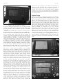
N
The official organ of the United Kingdom Maritime Pilots’Association
ATIO N
CI
E
PIL
O
UNI
•U
ALL
No.285
M
APRIL 2006
•
ED WE F
M A R I TI
AND
DIV
ID
M
WE
TED ST
ED KINGDO
T
I
OTS AS
S
Automatic Identification System (AIS)
TRANSPONDER UPDATE
“Virtual” …
Editorial
The good news this quarter is that the
UKMPA is at last going to be represented
within the group Port Skills and Safety
Limited (PSSL). PSSL took over from the
DfT funded British Ports Industry Training
(BPIT) in 2002 and whereas the UKMPA
had worked closely with BPIT to produce a
comprehensive document detailing National Occupational Standards for Maritime
pilots we were not invited to join the port
led commercial body of PSSL. It has
therefore taken four years of hard work by
both Norman McKinney and Les Cate
along with members of the Section
Committee to finally achieve an invitation
to participate on the group’s activities
relevant to pilots. The reason that this is
important is that PSSL, in conjunction with
some nautical colleges, have produced a
draft Foundation Degree for ports which
will include pilotage and it is therefore
essential that pilots are represented. The
UKMPA has only one agenda within PSSL
and that is safety and we will therefore be
using our membership to convince those
who may wish to reduce standards that it is
in the interests of the whole ports sector
that high standards of training and
qualifications for pilots are maintained in
the interests of ensuring the safety of ships,
port infrastructure and reputations!
John Clandillon-Baker
It is now just over one year since AIS
became mandatory for all SOLAS vessels
over 300 grt and although I must admit
that my prediction that the system would
have difficulty in coping with the amount
of traffic in port areas has been largely
proven wrong there are increasing cases of
ships’ units failing in a variety of functions.
These failures are about to gain in
significance as a result of the
implementation of Class B AIS for non
SOLAS vessels and, from 1st July 2008,
the requirement for new radars to have
AIS integration. It is therefore timely to
identify some of the problems that are
occurring with the existing systems.
… “Reality”
I am aware of three cases where total failure has resulted in vessels having to either send
their units away for repair or having to install a replacement set. This has meant that until
the AIS was repaired or replaced the vessels concerned were navigating without AIS and
were thus invisible to AIS tracking systems. With respect to other failures the most
common on-board malfunction is the misalignment between the gyro heading and the AIS
heading which results in the AIS heading either defaulting to North or the AIS heading
being incorrectly aligned. In the latter case this sometimes results from the unit being
switched off in port and if the heading is different when the unit is switched on again it
does not automatically align with the correct heading but defaults to north or retains the
original shut down heading. Unfortunately, such faults are not readily apparent to those
on board and are usually only identified by reports from other vessels or a VTS centre.
Fixing this alignment problem is also not straightforward on many vessels and I have
recently piloted a vessel where it was necessary to contact a service technician to resolve
this error. As experience is gained then these faults should normally be eliminated by
including the AIS gyro heading alignment on the pre sailing check list, but there is now a
new problem with this in that since the only training that most officers have received is
from the installation engineer, when new crews join who are unfamiliar with a particular
AIS unit they may have no idea how to undertake some operational procedures. This may
seem an unlikely scenario, but I was on one vessel recently which was reported as having
misaligned heading data and the gyro alignment interface was a via a small separate unit
with an adjustment dial tucked away underneath the wheelhouse console. Fortunately the
Mate had witnessed the installation, but this is not the sort of detail that would normally
In This Issue
Editorial:
John Clandillon-Baker
AIS Transponder Update
JCB
Pension News
Debbie Marten
EMPA Report
Letter to the Editor
Chairman’s Report
Joe Wilson,
Vice Chairman
PEC Working Group
MT Stolt Aspiration /
Tug Thorngarth MAIB Report, edited JCB
Mooring Bitts for Towage
Obituary
Insurance Details
Book Review
The Pilotage Act (1910)
2
April 2006
The Pilot
antennas can cause ‘masking’ in some directions and enhanced
sensitivity in other directions. Also, anomalous propagation of
VHF signals during particular climatic conditions can provide a
focusing effect, giving even very distant stations unusual
prominence. For these reasons the inbuilt features of SOTDMA do
not always ensure that closer stations are received in preference to
more distant stations.
Practical Useage
Picture 1. Two of our ships are missing!
be passed on during the usual few hours of a crew change! All this
of course does raise the point that surely in the 21st century,
technology should be able to eliminate such tedious and fiddly
operations!
Another problem which I have observed on some ships’ AIS is
the phenomena whereby AIS data either disappears (picture 1) or
the data defaults to the basic MMSI number. Because these effects
are not universal (other vessels and VTS are tracking the
“missing” target without problems) I have been advised that such
target corruption is most likely to be caused by poorly installed
equipment. However, and this is a problem that may become
serious with the introduction of the Class B AIS, such target loss
could also be caused by what is termed as “garbling” of the signal.
It is therefore of relevance to be aware as to how garbling may
arise and the following explanation is from a paper presented to
the Royal Institute of Navigation NAV05 Conference by Dr Andy
Norris who chairs the Technical Committee of the International
Electrotechnical Committee (IEC) that is responsible for issuing
technical standards for ships’ radio and navigation equipment:
AIS works on Time Division Multiple Access (TDMA)
transmissions. The basis of TDMA is that time is divided up into
discrete ‘slots’ and only one station (base-station, ship-station, etc)
will be transmitting during a particular time slot. For AIS there are
2,250 slots in every minute on each of the two AIS VHF channels,
which are known as AIS 1 and AIS 2. UTC is used as the time
reference. When an AIS Class A station is first switched on it predetermines its transmission slots by ‘listening’ to the existing
traffic. This establishes which slots are free, helped by stations
already ‘on-air’, which broadcast their future slot selection as part
of their transmitted messages. The fact that each station
determines its own slots within an organised regime gives this
technique the name ‘Self Organising TDMA’ (SOTDMA). In busy
areas unused slots become rare and then stations select slots
already in use by the most distant stations. These are readily
calculated because of the positional data contained within the AIS
messages. The organised reuse of slots from distant stations should
make AIS degrade “gracefully” as the number of stations in an
area increases by making the effective range of AIS decrease to
match the increase in station density. The characteristics of the
frequency modulated (FM) signal used by AIS helps in ensuring
that the strong signals from close stations are properly
demodulated in the presence of weaker signals from more distant
stations sharing the same slot. This is known as co-channel
interference rejection. However, if confronted with signals of
similar strength the demodulator becomes confused and ‘garbling”
occurs. In fact there are a number of mechanisms that can make
signals from distant stations similar in strength or even stronger
than some closer stations. For instance, poorly situated AIS
With respect to the type of equipment installed, the overwhelming
majority of vessels are fitted with the minimum required to comply
with carriage regulations! These are small alpha numeric displays
which at the absolute basic level have to display at least three
targets. I have seen such minimal three line units on ships and for
all practical purposes they are totally useless. Other systems cram
a list of many targets into the small display (typically 9cm x 12cm)
which renders them illegible and again these are totally useless.
The more sophisticated units, such as those manufactured by
SAAB and SAILOR, are fortunately the ones most commonly
fitted but due to the small screen size these also have severe
practical limitations in areas where several ships are present,
which of course is when it is likely to be of most benefit! These
intermediate sets offer a choice of display modes, with either a list
of targets being displayed or a by a graphic display similar to a
mini radar picture. On the graphic display (picture 2), selecting a
target for display is so fiddly that again it is impractical and in my
experience around 90% of vessels have the display set to the list
mode.
Picture 2. Selecting targets on the graphic display is fiddly
Picture 3. The target list by range is the normal mode of use
3
The Pilot
April 2006
Again there are several options for listing but the most useful is
the target list selected by range (picture 3) which displays the
MMSI number, the name of the vessel and its range and bearing.
By scrolling down the list a target can be selected and extended
data on the selected vessel can be obtained (picture 4). The
obvious place for sighting such displays is adjacent to the radar
where the bearing and rage of a radar target can be correlated with
the AIS display and a good example is shown in picture 5.
However, on many vessels the AIS is sited wherever there
happened to be some space when the set was delivered and this is
usually remote from the radar and quite frequently in a corner at
the back of the chart table! I have yet to come across any free
standing AIS unit that has an integrated anti collision warning
fitted should another AIS target enter a pre determined danger
zone around the own vessel, although such alarms are usually
present where AIS is integrated into the radar display.
Integrated AIS on radar
Picture 6. Radar with AIS and chart overlay
The integration of AIS onto the radar display is being received
with mixed enthusiasm by those on board using such systems and
much depends on the quality of the equipment and its installation.
Picture 6 shows a high quality display which provided very
accurate tracking with good correlation between the radar and
AIS vectoring although even this equipment revealed some offset
Picture 7. Radar and AIS target offset. Approx. 2 cables!
Picture 4. Extended data
Picture 5. ENC, Radar and IAS
(plus essential coffe mug - pink fluffy dice optional!)
between the radar and AIS targets (picture 7) and on other sets I
have observed offsets of up to 5 cables and this is one aspect of
integration which may cause a watch keeper to make an erroneous
interpretation of a developing situation. Another particularly
annoying “feature” of some AIS / radar integration displays is that
although the AIS function can be switched off, many such displays
that I have come across have had an automatic AIS proximity
alarm which triggers if another AIS vessel enters the radar’s anti
collision guard zone. One unforeseen result of this supposed safety
feature is that even when approaching a vessel at anchor or
moored alongside, the AIS “collision” alarm resounds around the
wheelhouse! The solution? The guard zone is set to zero and the
alarms are set to “mute” thus neatly disabling one of the primary
anti collision functions of the radar!!
One other fact is that I have yet to come across any Master or
Officer of the Watch (OOW) who has been on an AIS course or
received any formal instructions in its use. All knowledge on board
has therefore either been gained from a brief introduction from the
installation engineer or from the user manual. I believe (although
I hope that I am proven wrong again!) that this lack of formal
training is going to be a significant factor in vessel safety as Class
B units and AIS radar integration displays are introduced. These
two developments are designed to provide “additional
information to the OOW to enhance the situational awareness of
a developing situation with respect to collision avoidance”. This
all sounds admirable but the limitations which have been placed
on Class B AIS mean that both SOLAS and non SOLAS vessels
may receive incomplete and inaccurate data! The reason for this is
in the technical specifications of the Class B equipment and again
the following is an edited extract from an article on AIS B
implementation written by Dr Norris for the “Digital Ship” online magazine.
April 2006
AIS B offers leisure and other small vessel users a potentially
valuable tool to enhance maritime safety at an affordable price. It
has been designed to minimise degradation of the AIS network
and will be available in three options.
● The
basic unit is a display-less transmitter for up-mast
mounting to alert the vessel’s presence on SOLAS
vessels’ AIS in the same manner as a radar reflector does
now on radar.
● Intermediate
units have an inbuilt display (similar to the
Class A displays) which, as well as broadcasting ownship position, will enable users to see the positions and
vessel data of all AIS-fitted vessels in their vicinity on the
display.
● At
the top end of the market AIS overlay capability will
be added to radars and electronic chart systems, giving
sophisticated navigational information to the user, vying
with the facilities available on the most comprehensively
fitted SOLAS vessel.
With this prospect of eventual high usage in the leisure sector it is
worthwhile taking a look at some of the possible issues that may
arise with this increased use of AIS.
The Class B transponder transmits at a lower power (2 watts)
than Class A (12.5 watts) thus reducing the effective range of Class
B transmissions and their effect on the network. Also, position
reports are given at a maximum rate of once every 30 seconds, as
opposed to Class A systems, which typically transmit once every
10 seconds and up to every 2 seconds. Importantly, Class B
systems will give priority to Class A transmissions, delaying their
own transmissions if a Class A station is already transmitting. This
is the fundamental aspect of the Carrier Sense (CS) mode of
operation that is used by Class B. Tests have confirmed that the
AIS network is minimally affected even if there are relatively large
numbers of Class B vessels in any area.
Collision avoidance
AIS is considered to be a useful aid to improve situational
awareness but its use as an anti-collision device is not recognised
by the IMO.
The Collision Regulations (COLREGS) are written around the
concepts of visibility (sight) of vessels and the proper use of radar
and have not yet been revised to incorporate any reference to AIS.
However, Rule 5 of the COLREGS (Lookout) does emphasise the
use of ‘all available means’ to make a full appraisal of the situation
and of the risk of collision. It therefore appears that this rule
requires vessels that have AIS fitted to use the system as part of
such an appraisal, but not to take collision avoidance decisions
based solely on AIS data. What is fundamental is that AIS data
should only be used with the full knowledge that data errors are
possible and that not all targets may be transmitting data - an AIS
system may not be fitted or a fault may have developed.
4
The Pilot
Unfortunately, an uninformed Class B user with a reasonable
AIS display may base their own collision avoidance decisions
solely on AIS data thus creating significant problems for SOLAS
vessels.
Information overload?
The confusing excess of data when navigating in waters crowded
with Class B users will render AIS useless for most Class A users
fitted with the MKD. On a radar screen an excessive number of
AIS symbols will make the observation of raw radar data more
difficult and so the display of AIS targets may need to be inhibited
or an AIS target filter enabled. From July 2008 all new navigation
displays capable of showing AIS targets will need to meet IMO
performance standards which require that AIS filters must be
included ‘in order to ensure that the clarity of the total
presentation is not substantially impaired’. Increasingly
sophisticated AIS filters may have to be developed but
unfortunately it is difficult to make filters sufficiently adaptable to
be effective whilst not obscuring possibly dangerous targets.
This article has highlighted some very relevant points and both the
AIS B and radar AIS integration have the potential to create a
dangerously confusing picture to the hapless navigator, especially
in reduced visibility. I have previously identified a major problem
with AIS integration on radar and the addition of Class B AIS into
the already crowded display has the potential to create a
nightmare scenario. In view of the fact that data update
transmissions AIS B vessels are going to be at least 30 seconds
apart and in busy areas may not update at all means that the
information will be historic and therefore totally unreliable and
this, coupled with an automatic collision alarm function has the
potential to create so much information overload as to render the
display unusable (picture 8). Dr Norris’ article refers to filtering
but correctly identifies the problem of actual dangerous targets
then being missed. Couple this with the fact that leisure users are
going to assume that they are being accurately plotted and
carefully tracked by the professional navigators of the “bridge
team” I don’t believe that the word nightmare is at all
inappropriate! As if these factors are not sufficiently worrying
there is a also move by IALA, buoyed by an enthusiasm for enavigation by the shipping Minister and DfT, to introduced AIS
based “virtual” navigation marks to replace the traditional
physical marks! Considering that the original full implementation
date for AIS by IMO was December 2008, which was accelerated
by four years following pressure from the USA’s security agenda, I
personally feel that the AIS has been implemented without a
proper assessment of the practical useage through structured
operator feedback and to now release the system into the leisure
AIS displays
It is of extreme importance to the Class B user to be aware that
there is no statutory requirement for SOLAS vessels to be able to
display AIS targets on a screen merely a requirement to provide a
simple alphanumeric Minimum Keyboard and Display (MKD). To
meet the minimum requirements this display need show no more
than three ships at any one time detailing bearing, range and name
of ship. Therefore Class B users must understand that their vessel
may not be appearing as a ‘bright beacon’ on the displays of the
majority of SOLAS vessels. Although IMO requires all new radars
fitted after 1 July 2008 to have good AIS display capabilities,
existing radars will not have to be upgraded and so it will be many
years before AIS data can be effectively used for navigation on
many SOLAS vessels.
A developing situation.
Will the inclusion of Class B AIS result in information overload?
5
The Pilot
market is sheer folly, not least because it is sure to tempt some
leisure sailors to proceed in restricted visibility when they would
normally remain in the marina. Just in case you may have any
lingering doubts that I am exaggerating, there is already a British
company called NASA Marine manufacturing an AIS receiver
(note no transmitter included!) unit for the leisure market called
“AIS radar”! The product description is as follows:
The Nasa Marine AIS radar is the first stand alone AIS receiver /
plotter specifically designed for the leisure boat market. The display,
with ranges of 1, 2, 4, 8,16 and 32 nautical miles shows AIS carrying
vessels in a format normally associated with conventional radar. A
trail of previous positions clearly chows the relative track of all the
targets on the screen. A box to the right of the screen displays the
speed over the ground, the vessel name, mmsi number and the
latidude (sic) and longitude of any target selected by the user.
April 2006
Chart display and Information System (ECDIS) which can replace
the paper chart folio, the vast majority of ENC’s currently in use
do not meet the stringent specifications of an ECDIS for accuracy
and corrections and come with the warning “Not to be used for
navigation”! It is for this reason that radar has been chosen as the
AIS screen display platform but I believe that with all the different
radars incorporating the manufacturers (usually incorrect) ideas as
to how information is accessed and presented to the user
dangerous confusion will be the inevitable result of the rush to
embrace AIS. However, I have been proven wrong so far so I am
sure that I will be proven wrong again. I hope so!
JCB
My thanks to Dr. Andy Norris for his kind permission to use the
texts included with this article.
Feedback Required
The Future?
The best installations that I have seen are where there is an
Electronic Navigation Chart (ENC) display adjacent to the radar.
The ENC automatically displays all AIS targets and is integrated
with the radar so that any radar targets being plotted are also
displayed on the chart. In this way the watch keeper can
concentrate on using the radar equipment for which he should
have been fully trained but can also refer to the ENC for an
overview of the vesselís position and can monitor and obtain
extended AIS information from this secondary system without
interfering with the familiar radar detail which he has been trained
to use. Unfortunately there are two major problems with this
arrangement. Firstly there is no requirement to carry an ENC and
secondly, in contrast to the still rare officially licensed Electronic
Y-TRONICS
Whilst I was preparing the AIS update
feature I was contacted by a German
company called Y-Tronics who market
AIS hardware units and accessories. One
item which will be of particular interest
to pilots is a “Bluetooth” connector to
remotely link a pilot’s laptop to a vessel’s
AIS pilot plug. Ed Neale from Milford
Haven is going to be testing this
equipment on their pilot docking PDAs
and laptop units so I hope to have a full
report in a future issue.
Weblink:
www.y-tronic.com/english/start_en.htm
JCB
Feedback on experiences with all aspects of AIS are urgently
required and reports should be sent to the dedicated “forum” link
on the Nautical Institute website at: www.nautinst.org/ais/
Pilots are ideally placed to provide valuable input through their
experiences on a wide range of ships in varying environments. All
information received is passed on to the relevant experts who
will use it to identify and resolve operational problems, so please
participate.
Serious errors should also be reported to the MCA on the form
attached to MIN 231.
Other MCA advice on AIS is contained within MGN 277 and
MSN 1975.
AIS Solutions for Pilots
Pilot-AIS Software
Displays AIS data according to IMO regulations on
your laptop with an easy-to-use software tuned
to your requirements.
Wireless Pilot Port Interface
The Bluetooth Pilot Plug connects your
Personal Pilot Unit or laptop without any
wire to the AIS Pilot Port.
Pilot Port Quick Test
The Pilot Port Test Device enables pilots,
PSC officers, surveyors and technicians to
check the cabling of an AIS Pilot Port
within seconds.
http://www.y-tronic.com
email: [email protected]
Y-tronic GbR, Auf Feiser 30, D-54292 Trier, Germany
phone: +49-441-5947751
Bluetooth Pilot Plug