1
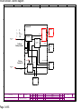
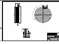
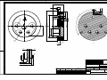
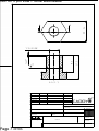
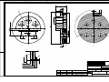
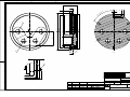
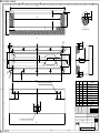
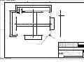
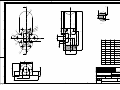
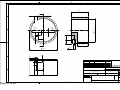
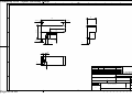
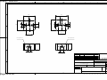
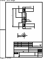
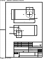
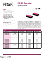
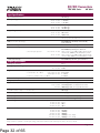
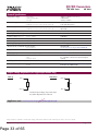
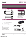
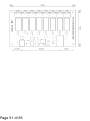
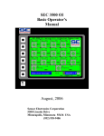
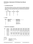
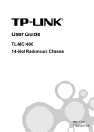
Battery canister - electric diagram 1 2 3 4 5 6 7 8 A A Depth sensor Sick 6038689 Battery Canister 4-20mA Depth B B 1 CRYDOM CMXE60D20 Unregulated 48 V 2 5V BMS fuse 20A 3 1 4 1 Traco TEN 60 +5V supply C Traco TEN 60 +12V supply 4 5 2 24 V 4 C 3 5 46.8 V Traco TEN 60 +24V supply 4 3 3 12 V 1 2 5 9V TSR 1-2490 2 TSR 1-2490 9V D D GND Magnetic Vehicle ON/OFF switch E F E Faculty of Ele ctrical Engine ering and Computing (FER), Department o f Co ntr ol a nd Co mpu ter Eng ineerin g Lab oratory for Un derwater systems a nd techno logies Page 1 of 65 Pro ject: CADDY SYS TE M: HARDWARE SUBJECT: CADDY vehicle Bud dy - Block Drawing NAME DRAWN BY CHECKED BY APPROVED BY. DATE Antonio Vasilijevic 15.01.2014 . SIG . DWG. NO.: B A ISSUE Modified FIRST DRAWN MODIFICA TION DATE NAME SHEET: LAP OST 1-14 01/03 ISSUE: A F Master canister - electric diagram 1 2 3 4 5 6 7 8 A A Acoustic Modem Fiber Tether R2 24V Regulated 3. +, 7. - B C GPS antenna WiFi antenna To/From Battery Canister Regulated supplies Sheet 01/03 A7-E7 48V unregulated 1. 2. 3. 4. 5., 6. 9V 12V 5V 24V GND B Serial 1. Tx from terminal 2. Rx from terminal 4. GND Canister #1 Power Distribution board Ethernet Power Relay board Two power cables 1., 2. 48V 3., 4. GND USB Serial CPU R8, NC, 5V Fiber – Ethernet Converter Advantech IMU Microstrain USB Ethernet Ethernet Power Relay board. R1R6 to thrusters 1-6 C Supply 5V RS485 Thruster motor drives 2(white), 3(pink), 4(green) + 6(blue), 7(white/black), 8(pink/black) - Type: Drivers integrated into the motors, VideoRay design with UNIZG cooler D USB Memory stick Supply 9V Ethernet HUB D 1 (black): RS485 + 5 (orange): RS485 - R1 24V Regulated 3. + 7. - Serial 1. Tx from terminal 2. Rx from terminal 4. GND E Ethernet Supply Serial Ethernet E M DVL BlueTooth for Tablet To/From Canister #2 M 6X F Faculty of Ele ctrical Engine ering and Computing (FER), Department o f Co ntr ol a nd Co mpu ter Eng ineerin g Lab oratory for Un derwater systems a nd techno logies Page 2 of 65 Sheet 03/03 D2 Project: CADDY SYSTEM: HARDWARE SUBJECT: CADDY vehicle Buddy - Block Drawing DRAWN BY CHECKED BY APPROVED BY. NAME DAT Antonio 15.01.2014. E Vasilijevic SIG . DWG. NO.: B A ISSUE Modified FIRST DRAWN MODIFICATION DATE NAM E SHEET: LAP OST 1-14 02/03 ISSUE: A F Vision canister - electric diagram 1 2 3 4 5 6 7 8 A A Canister #2 B 1. 2. 3. 4., 5. 6., 7. 8. 9. 9V 12V 24V GND Battery reset Charge + Charge - Sheet 01/03 A7-E7 B LED Module Supply Ethernet Power Relay board R8 12V CPU Supply Type: INTEL NUC To/From Battery Canister C LED Light Comms FireWire C Stereo Camera Front DC/DC 24/31V To/From Canister #1 D Supply 9V Serial - Tilt Control Ethernet R6, 12 V D TIlt Camera Ethernet HUB Sheet 02/03 E6 Ethernet Ethernet R5, 31 V E E ARIS Sonar F Faculty of Electrical Engineering and Computing (FER), Department of Control and Computer Engineering Laboratory for Underwater systems and technologies Page 3 of 65 Project: SYSTEM: CADDY HARDWARE SUBJECT: CADDY vehicle Buddy - Block Drawing DRAWN BY CHECKED BY APPROVED BY. NAME DATE Antonio Vasilijevic 29.08.2014 DWG. NO.: SIG. B A ISSUE Modified FIRST DRAWN SHEET: DATE NAME LAPOST 1-14 03/03 ISSUE: B F Battery and Vision canister - Cap 1 1 2 3 4 5 6 7 8 9 10 11 12 32 A M5 3 uv r ta po d 120 ° B 12,5 7 10 B 170 160,7 C D E C B-B F B 4,05 G 4,05 R0 ,5 Ime i prezime Milan Markovic Datum Projektirao Razradio Crtao Pregledao H 9,5 Potpis Milan Markovic Objekt: Objekt broj: 3,5 3,9 R. N. broj: Napomena: Materijal: C (2 : 1) I Page 4 of 65 Kopija Sva nekotirana skošenja 1x45° Masa: Naziv: Pozicija: Čep 1 Mjerilo originala 1:1 A2 Listova: Crtež broj: 0 Format: List: 10 20 30 40 50 60 70 80 90 100 Battery canister - Cap 2 1 2 3 4 5 6 7 8 9 10 11 12 55 A 20 25 R19 3 3u v rt a po B d1 20 ° G1/4 M5 12,5 7 10 B 23 C 125 4 170 1 160,7 Y X 38 3 38 54 2 D 35 R19 E B C B-B F 4,05 R0 ,5 4,05 G Ime i prezime Milan Markovic Datum 9,5 H 3,5 Projektirao Razradio Crtao Pregledao 3,9 Objekt: Potpis Milan Markovic Objekt broj: R. N. broj: C (2 : 1) I Page 5 of 65 Napomena: Provrt 1 2 3 4 X LOC -40 -20 20 40 Y LOC 0 -35 -35 0 Dimenzija 14,50 - M16x1.5 14,50 - M16x1.5 14,50 - M16x1.5 14,50 - M16x1.5 Kopija Sva nekotirana skošenja 1x45° Materijal: Masa: Naziv: Pozicija: Čep 2 Mjerilo originala 1:1 A2 Listova: Crtež broj: 0 Format: List: 10 20 30 40 50 60 70 80 90 100 Battery and Master canister - Cylinder 1 2 3 4 5 6 7 8 9 10 11 12 A 170 410 A 60° d po B 6p B rt rov a 5 16 C A 1 B C D B-B (1 : 2) 160 A-A (1 : 2) Elektrostatski prevučeno E Dosjedanje O-ring brtve (fina obrada) 0,50 F 30 2 5 G Ra 0,2 30° 0,25 H Ime i prezime Milan Markovic Datum Projektirao Razradio Crtao Pregledao Potpis Milan Markovic Objekt: Objekt broj: R. N. broj: 90° Kopija Napomena: C (5 : 1) Materijal: Masa: Naziv: I Page 6 of 65 Pozicija: Cijev 1 Mjerilo originala 1:2 A2 Listova: Crtež broj: 0 Format: List: 10 20 30 40 50 60 70 80 90 100 Nut for 9 pin Low Profile Bulkheads Page 7 of 65 A O.K. 24 A 17 27,5 19,5 1x45° 7/16-20 UNF A-A (2 : 1) Datum Projektirao Razradio Crtao Pregledao Ime i prezime Milan Markovic Potpis Milan Markovic Objekt: Objekt broj: R. N. broj: Kopija Napomena: Masa: Materijal: Naziv: Pozicija: Matica Mjerilo originala Crtež broj: Format: Listova: List: Master canister - Cap 1 2 3 4 5 170 7 8 9 10 11 12 C-C (1 : 1) A-A (1 : 1) A D R7 5 2x45° 12,5 C 10 A 6 R12 1 R12 M5 0° 6 od p rta v 6u R3 4 15 50 R3 X 3 160,7 45° Y 1 R6 0 100 117,5 C 20 D 5 11, 5 2 35 B E 17 B A C 32 85 F 4,05 4,05 5 40 +0,25 22 +0,15 1x45° G 0 2,25 R0 ,5 H 3,9 Page 8 of 65 Potpis Milan Markovic Objekt: 3,5 9,5 I Ime i prezime Milan Markovic Datum Projektirao Razradio Crtao Pregledao B (2 : 1) D (2 : 1) Provrt X Y 1 2 3 4 5 -56 -37 -19 19 37 -17,5 -47 -17,5 -17,5 -47 R. N. broj: Dimenzija 10 10 10 10 10 - 7/16-20 7/16-20 7/16-20 7/16-20 7/16-20 Objekt broj: Napomena: UNF UNF UNF UNF UNF Kopija Sva nekotirana skošenja 1x45° Materijal: Masa: Naziv: Pozicija: Čep 3 Mjerilo originala 1:1 Format: A2 Listova: Crtež broj: 0 List: 10 20 30 40 50 60 70 80 90 100 Master canister - Cap 2 1 2 3 4 5 6 7 8 9 10 11 12 55 A 7 R 63 M5 10 23 12,5 B ,5 0 30 2 1 35 3 170 Y 160,7 10 C 3u vrt ap od 120 ° B X 35,5 17 35,5 11,50 30 D 20 11,50 11,50 E C B B-B F 4,05 4,05 R0 G ,5 Ime i prezime Milan Markovic Datum 2,25 9,5 H Projektirao Razradio Crtao Pregledao 3,5 Potpis Milan Markovic Objekt: 3,9 Objekt broj: R. N. broj: Napomena: C (2 : 1) Materijal: I Page 9 of 65 Provrt X LOC Y LOC 1 2 3 -34,6 0 34,6 20 40 20 Dimenzija 14,50 - M16x1.5 14,50 - M16x1.5 14,50 - M16x1.5 Kopija Sva nekotirana skošenja 1x45° Masa: Naziv: Pozicija: Čep 4 Mjerilo originala 1:1 A2 Listova: Crtež broj: 0 Format: List: 10 20 30 40 50 60 70 80 90 100 Vision canister - Cylinder 1 2 3 4 5 6 7 8 9 10 11 12 A 170 300 A 60° d po B 6p B rt rov a 5 16 C A 1 B C B-B (1 : 2) D 160 A-A (1 : 2) Elektrostatski prevučeno E F Dosjedanje O-ring brtve (fina obrada) 2 5 G Ra 0,2 0,50 30 30° Ime i prezime Milan Markovic Datum Projektirao Razradio Crtao Pregledao H Potpis Milan Markovic Objekt: 90° C (5 : 1) Objekt broj: R. N. broj: Kopija Napomena: Materijal: Masa: Naziv: I Page 10 of 65 Pozicija: Cijev 2 Mjerilo originala 1:2 A2 Listova: Crtež broj: 0 Format: List: 10 20 30 40 50 60 70 80 90 100 Vision canister - Cap 2 1 2 3 4 5 6 7 8 9 10 11 12 60 A 7 6 ta 6 R 21 B r uv d po M5 0° 12,5 28 10 B 4 170 1 150 Y 160,7 C X 42 3 42 2 64 D 35 R 21 E B C B-B F 4,05 R0 ,5 4,05 G Ime i prezime Milan Markovic Datum 3,5 Projektirao Razradio Crtao Pregledao 3,9 Objekt: 9,5 H Potpis Milan Markovic Objekt broj: R. N. broj: C (2 : 1) I Page 11 of 65 Napomena: Provrt X LOC Y LOC 1 2 3 4 -50 -25 25 50 0 -43,3 -43,3 0 Dimenzija 18,50 18,50 18,50 18,50 - M20x1.5 M20x1.5 M20x1.5 M20x1.5 Kopija Sva nekotirana skošenja 1x45° Materijal: Masa: Naziv: Pozicija: Čep 6 Mjerilo originala 1:1 A2 Listova: Crtež broj: 0 Format: List: 10 20 30 40 50 60 70 80 90 100 Stereo camera - Front Glass 1 2 3 4 5 6 7 8 8 80 A 80 82 34 34 11,8 29,2 11,8 29,2 6 R1 B 7,50 C 322 D rub zaobliti Ime i prezime Milan Markovic Datum E Projektirao Razradio Crtao Pregledao Potpis Objekt: Objekt broj: R. N. broj: Napomena: Materijal: Kaljeno staklo F Page 12 of 65 Kopija Svi provrti 7,5 mm Masa: Naziv: Pozicija: Mjerilo originala 1:1 Staklo stereo kamere Listova: Crtež broj: 0 Format: List: 10 20 30 40 50 60 70 80 90 100 Stereo camera - housing 1 2 3 4 5 6 7 8 9 10 11 12 B 3 5 8 A 3 324 76 B 11 43 278 B (2 : 1) utor za O-ring 210x4 15 R3 8 40 38 A M6 3 R1 49 40 10 A R1 15 5 R 90 6 7/16-20 UNF D 4 84 2 X M6 8 R8 Y 8 A-A C E 1 3 5 7 9 3 R2 0 7 R1 289 F 12 identična 4 uvrta s obje strane kučišta 30 20 20 12 15 G 30 Uvrt X Y 1 2 3 4 5 6 7 8 9 10 74 16 79 11 79 11 79 11 74 16 16 16 85 85 165 165 245 245 314 314 Projektirao Razradio Crtao Pregledao H Dimenzija 5 - M6 5 - M6 5 - M6 5 - M6 5 - M6 5 - M6 5 - M6 5 - M6 5 - M6 5 - M6 Ime i prezime Milan Markovic Datum 10.07.14. Objekt: Potpis Objekt broj: R. N. broj: Kopija Napomena: svi uvrti iz tablice su jednake dubine Materijal: POM-c (crne boje) Masa: 330 I Page 13 of 65 Naziv: Pozicija: Kučište st. kamere(poliacetal) Mjerilo originala 1:1 Format: A2 Listova: Crtež broj: 0 200-5-001 10 20 30 List: 40 50 60 70 80 90 100 Mono camera - cylinder Page 14 of 65 Mono camera - Cap 1 Page 15 of 65 Mono camera - Cap 2 Page 16 of 65 Tablet - Front glass áá áá áá áá " 8 áá áá á á ! # áá $ á á2 % QTAáY@NAKHSH 0QNIDJSHQ@N 2@YQ@CHN #QS@N 0QDFKDC@N -DMSNQ /AIDJS )LDáHáOQDYHLD -HK@Má-@QJNUHB $@STL 0NSOHR -HK@Má-@QJNUHB /AIDJSáAQNI 2á.áAQNI .@ONLDM@ & Page 17 of 65 +NOHI@ 3UHáOQNUQSHááLL -@SDQHI@K +@KIDMNáRS@JKNáLL -@R@ 8 .@YHU 0NYHBHI@ 0QDCMIDáRS@JKN -IDQHKNáNQHFHM@K@ ,HRSNU@ #QSDèáAQNI &NQL@S ,HRS Tablet - Rear glass áá áá á á á á ! 8 áá áá áá áá áá " áá # $ á2 á áá % QTAáY@NAKHSH 0QNIDJSHQ@N 2@YQ@CHN #QS@N 0QDFKDC@N -DMSNQ /AIDJS )LDáHáOQDYHLD -HK@Má-@QJNUHB $@STL 0NSOHR -HK@Má-@QJNUHB /AIDJSáAQNI 2á.áAQNI .@ONLDM@ & Page 18 of 65 +NOHI@ RUHáUDBHáOQNUQSHááLLáL@MIHáLL -@SDQHI@K +@KIDMNáRS@JKNáLL -@R@ 8 .@YHU 0NYHBHI@ :@CMIDáRS@JKN -IDQHKNáNQHFHM@K@ ,HRSNU@ #QSDèáAQNI &NQL@S ,HRS Tablet - Housing 1 2 3 4 5 6 7 250 A 8 A-A 16,5 A 4,5 R2 26 10 1 R2 0 ,75 7,5 B R1 6 R8 184 168 209,5 227 C 269 16,5 291,5 266 15 R1 7 25 D 4 ,5 5 R2 5 A E Utor za brtvu (O-RING) Ime i prezime Milan Markovic Datum 309 Projektirao Razradio Crtao Pregledao Mentor Objekt: Potpis Milan Markovic Objekt broj: 351 R. N. broj: Kopija Napomena: Materijal: POM-c F Page 19 of 65 Masa: Naziv: Pozicija: Okvir kucista Mjerilo originala 1:2 0 Listova: 128-7-001 Crtež broj: 10 20 30 40 Format: List: 50 60 70 80 90 100 VideoRay PRO4 - Thruster mount 1 2 3 4 5 6 7 8 9 10 11 1,50 A 12 3 R1 5 A B 42,25 1,7 ,5 0 0 1 R 0 R7 ,5 R6 8 R6 95 4,50 6 B (5 : 1) 14,50 C R8 10 4 3 9 17 X LOC Y LOC 1 -20 0 2 20 0 3 -12,5 -9 4 -12,5 9 5 -8,5 -20,9 6 -8,5 20,9 7 8,5 -20,9 8 8,5 20,9 9 12,5 -9 10 12,5 9 4,50 5 PROVRT B R6 E 12 29,35 2 11 1 34 10 Y 11 D 7 DIMENZIJE 5 THRU ALL M6 - 6H THRU ALL 5 THRU ALL M6 - 6H THRU ALL 2,50 7,50 M3 - 6H 6 2,50 7,50 M3 - 6H 6 2,50 7,50 M3 - 6H 6 2,50 7,50 M3 - 6H 6 2,50 7,50 M3 - 6H 6 2,50 7,50 M3 - 6H 6 2,50 7,50 M3 - 6H 6 2,50 7,50 M3 - 6H 6 X R1 5 F 25 A A-A (2 : 1) 27 10 G Ime i prezime Milan Markovic Datum 30 Projektirao Razradio Crtao Pregledao H Potpis Objekt: Objekt broj: R. N. broj: Napomena: Materijal: M16x1.5 I Page 20 of 65 eloksirati Al Kopija 8 komada Masa: Naziv: 56 Pozicija: Montaza motora Mjerilo originala 2:1 Listova: Crtež broj: 0 Format: List: 10 20 30 40 50 60 70 80 90 100 VideoRay Pro4 - Thruster mount cap Page 21 of 65 A 5 6,50 6 3,20 3 A A-A Datum Projektirao Razradio Crtao Pregledao Ime i prezime Milan Markovic Objekt: Potpis Objekt broj: R. N. broj: Napomena: Materijal: Masa: Naziv: Pozicija: Format: Poklopac nosaca Mjerilo originala 1:1 Kopija 6 komada Listova: Crtež broj: List: VideoRay Pro4 - Motor controller heatsink 1 2 3 4 5 A 6 7 8 28 A 6 10 3,5 9 40,50 ,5 R1 R1 ,5 B 7 C 4 M3 9 A 18 46,5 A-A 5 D 4,20 M3 Ime i prezime Milan Markovic Datum Projektirao Razradio Crtao Pregledao E 13 Objekt: Objekt broj: R. N. broj: Napomena: Materijal: Sva skošenja 1x45° Al F Page 22 of 65 Potpis Masa: Naziv: Pozicija: Mjerilo originala 2:1 Kopija 8 komada Hladnjak Listova: Crtež broj: 0 Format: List: 10 20 30 40 50 60 70 80 90 100 VideoRay Pro4 - Motor controller clamp 1 2 3 4 5 6 7 8 A 14 36 2x45° 2x45° B C 2x45° 3 6,50 10 21,4 22 5 4 3 D 5 Ime i prezime Milan Markovic 5 Datum E Projektirao Razradio Crtao Pregledao Objekt: Potpis Objekt broj: R. N. broj: Kopija Napomena: Materijal: Al F Page 23 of 65 8 komada Masa: Naziv: Pozicija: Mjerilo originala 2:1 Format: Spojnica hladnjaka Listova: Crtež broj: 0 List: 10 20 30 40 50 60 70 80 90 100 20 6 17 6,50 M6 12 24 ,5 0 R3 R3 Page 24 of 65 R8 8 VideoRay Pro4 - Thruster flange 38 58 Datum Projektirao Razradio Crtao Pregledao Ime i prezime Milan Markovic Objekt: Potpis Objekt broj: R. N. broj: Napomena: Materijal: Masa: Naziv: Pozicija: Format: Prihvat nosaca motora Mjerilo originala 2:1 Kopija 8 komada Listova: Crtež broj: List: Frame - All POM-C parts Page 25 of 65 Frame - Lock nut 1 2 3 4 5 6 7 8 A 22 10 10 22 M5 M5 20 M5 M5 20 B C 13 13 Varijanta 1 Varijanta 2 M6 12 12 D 6 Ime i prezime Milan Markovic Datum E Projektirao Razradio Crtao Pregledao Potpis Objekt: Objekt broj: R. N. broj: Napomena: Sva skosenja 2x45° Materijal: F Page 26 of 65 Masa: Naziv: Pozicija: Mjerilo originala 2:1 Kopija Po 12 komada obje varijante Format: Listova: Crtež broj: 0 List: 10 20 30 40 50 60 70 80 90 100 Page 27 of 65 90 45 20 M10 15 Frame - DVL hinge 9 5 20 M10 15 20 Datum Projektirao Razradio Crtao Pregledao Ime i prezime Milan Markovic Objekt: Potpis Objekt broj: R. N. broj: Napomena: Sva skosenja 1x45° Materijal: Masa: Naziv: Pozicija: Format: Prihvat DVL obujmice Mjerilo originala 1:1 Kopija 2 komada Listova: Crtež broj: List: Frame - Stereo camera mount 10 6,50 5 20 10 5 1x45° Page 28 of 65 M5 Datum Projektirao Razradio Crtao Pregledao Ime i prezime Milan Markovic Objekt: Potpis Objekt broj: R. N. broj: Napomena: Materijal: Masa: Naziv: Pozicija: Prihvat bumblebee nosača Mjerilo originala (5 : 1) Kopija 4 komada Crtež broj: Format: Listova: List: Frame - Sonar mounting hinge B-B (2 : 1) R1 B 2, 5 M8 30 R3 10 2x45° 5 12,50 B Page 29 of 65 9 M5 9 15 12,50 M5 42,50 Datum Projektirao Razradio Crtao Pregledao Ime i prezime Milan Markovic Objekt: Potpis Objekt broj: R. N. broj: Napomena: Materijal: Masa: Naziv: Pozicija: Prihvat multibeam nosača Mjerilo originala 2:1 Kopija 4 komada Crtež broj: Format: Listova: List: Page 30 of 65 DC/DC Converters TEN 60N Series, 60 Watt CB ing nd e p UL 60950-1 UL 60950-1 Scheme Features ◆ 2” x 1” metal package ◆ Wide 2:1 input voltage range 9–18, 18–36, 36–75 VDC ◆ High efficiency up to 92% ◆ Adjustable output voltage ◆ No minimum load required ◆ Operating temperature range –40°C to +85°C ◆ Input filter to meet EN55022, class A ◆ Remote On/Off ◆ Under voltage lockout ◆ Lead free design, RoHS compliant ◆ 3-year product warranty The TEN 60N series is a family of high performance 60 Watt dc/dc converter modules featuring wide 2:1 input voltage ranges in a six side shielded 2” x 1” metal package with industry standard footprint. Standard features include remote On/Off, over voltage protection, under voltage lockout and short circuit protection. High efficiency across load range and low input current characteristics at no load make these converters the ideal solution for battery-operated systems. Typical applications are in wireless networks, telecom/datacom, industry control systems and measurement equipment. Models Order code TEN 60-1211N TEN 60-1212N TEN 60-1213N TEN 60-1215N TEN 60-1222N TEN 60-1223N TEN 60-2411N TEN 60-2412N TEN 60-2413N TEN 60-2415N TEN 60-2422N TEN 60-2423N TEN 60-4811N TEN 60-4812N TEN 60-4813N TEN 60-4815N TEN 60-4822N TEN 60-4823N http://www.tracopower.com Page 31 of 65 Input voltage range 9 – 18 VDC (12 VDC nominal) 18 – 36 VDC (24 VDC nominal) 36 – 75 VDC (48 VDC nominal) Output voltage 5.0 VDC 12 VDC 15 VDC 24 VDC ±12 VDC ±15 VDC 5.0 VDC 12 VDC 15 VDC 24 VDC ±12 VDC ±15 VDC 5.0 VDC 12 VDC 15 VDC 24 VDC ±12 VDC ±15 VDC Output current max. Efficiency typ. 12‘000 mA 5000 mA 4000 mA 2500 mA ±2500 mA ±2000 mA 12‘000 mA 5000 mA 4000 mA 2500 mA ±2500 mA ±2000 mA 12‘000 mA 5000 mA 4000 mA 2500 mA ±2500 mA ±2000 mA 90.5 % 90.5 % 91.5 % 91.5 % 90 % 90 % 92 % 92 % 92 % 92 % 90 % 90 % 92 % 92 % 92 % 92 % 91 % 91 % Page 1 of 4 DC/DC Converters TEN 60N Series 60 Watt Input Specifications Input current at no load 10 mA typ. Start-up voltage 12 Vin models: < 9.0 VDC 24 Vin models: < 18 VDC 48 Vin models: < 36 VDC Under voltage shut down (lock-out circuit) 12 Vin models: 8.0 VDC typ. 24 Vin models: 16 VDC typ. 48 Vin models: 32 VDC typ. Surge voltage (1 sec.) 12 Vin models: 25 V max. 24 Vin models: 50 V max. 48 Vin models: 100 V max. Conducted noise EN 55022 class Awith external components filter proposal to be adviced ESD (electrostatic discharge) EN 61000-4-2, air ±8 kV, contact ±6 kV, perf. criteria A Radiated immunity EN 61000-4-3, 20 V/m, perf. criteria A Fast transient / surge (with external input capacitor) – external input capacitor 12 & 24 Vin models: 48 Vin models: EN 61000-4-4, ±2 kV, perf. criteria A EN 61000-4-5, ±2 kV perf. criteria A Nippon chemi-con KY 220 µF, 100 V, ESR 48 mOhm and TVS 58V, 3000W peak (SMDJ58A) in parallel Nippon chemi-con KY 220 µF, 100 V, ESR 48 mOhm and TVS 120V, 3000W peak (SMDJ120A) in parallel Conducted immunity EN 61000-4-6, 10 Vrms, perf. criteria A Output Specifications Voltage set accuracy ±1 % Voltage adjustment range (single output models only) 15 & 24 VDC models: +20%, -10% other models: ±10 % Regulation – Input variation Vin min. to Vin max. – Load variation 0 – 100 % single output models: dual output models: – Load cross variation 25 % / 100 % 0.2 % max. 0.5 % max. 1 % max. 5 % max. Minimum load not required Temperature coefficient ±0.02 %/K Ripple and noise (20 MHz bandwidth) Start up time (constant resistive load) 5.0 VDC: 100 mVp-p max. with 10µF/25V X7R MLCC 12 & 15 VDC: 125 mVp-p max. with 10µF/25V X7R MLCC 24 VDC: 200 mVp-p max. with 4.7µF/50V X7R MLCC – Power On 60 ms typ. – Remote On 60 ms typ. Transient response (25% load step change) 250 µs typ. Short circuit protection continuous, automatic recovery Over load protection 150 % of Iout max. typ. hiccup Over-voltage protection (Zener diode, single output models only) 5 VDC models: 12 VDC models: 15 VDC models: 24 VDC models: 6.2 V 15 V 20 V 30 V Capacitive load (max. values) 30’000 µF 5850 µF 3900 µF 2000 µF 3900 µF (each output) 2400 µF (each output) 5.0 12 15 24 ±12 ±15 VDC VDC VDC VDC VDC VDC models: models: models: models: models: models: All specifications valid at nominal input voltage, full load and +25°C after warm-up time unless otherwise stated. http://www.tracopower.com Page 32 of 65 Page 2 of 4 DC/DC Converters TEN 60N Series 60 Watt General Specifications Temperature ranges – Operating –40°C to +85°C (with derating) – Casing temperature +105°C max. – Storage –55°C to +125°C Power derating – Natural convection 2.5 %/K above 50°C – Natural convection with heat sink (optional) 2.25 %/K above 55°C Thermal impedance – Natural convection 10.8 K/W – Natural convection with heat sink (optional) 10.3 K/W Over-temperatur protection at 115°C Humidity (non condensing) 5 – 95 % rel. H Isolation voltage (60 sec.) – Input / Output 1500 VDC Isolation resistance – Input / Output >1 GOhm Isolation capacitance – Input / Output 2’200 pF max. Switching frequency 250 kHz typ. (pulse width modulation PWM) Thermal shock, mechanical shock & vibration MIL-STD-810F – Test conditions www.tracopower.com/products/mil810.pdf Safety standards UL/cUL 60950-1, IEC/EN 60950-1 Safety approvals – UL/cUL (entry pending) www.ul.com -> certifications -> File e188913 Remote On/Off – On: 3.0 ... 12 VDC or open circuit – Off: 0 ... 1.2 VDC or short circuit pin 2 and pin 6 – Off idle current: 3.0 mA Reliability, calculated MTBF (Telcordia SR-332, 50% stress, Ta=40°C) 2.6 Mio. h Environmental compliance – Reach www.tracopower.com/products/reach-declaration.pdf – RoHS RoHS directive 2002/95/EC Output Voltage Adjustment (for single output models only) Trim up Trim down Trim +Vout Rd Ru Trim - Vout Nominal output voltage at open Trim input Ru, Rd for adjustment to be adviced g din n Application note: www.tracopower.com/products/ten60n-application.pdf pe All specifications valid at nominal input voltage, full load and +25°C after warm-up time unless otherwise stated. http://www.tracopower.com Page 33 of 65 Page 3 of 4 DC/DC Converters TEN 60N Series 60 Watt Physical Specifications Casing material copper Baseplate material non conductive FR4 Potting material silicon (UL94V-0 rated) Weight 33 g (1.16 oz) Soldering temperature max. +265°C / 10 sec. Outline Dimensions 3 (0.1) 2.54 5 Pin-Out 6 25.4 (1.0) Bottom View (0.8) 4 (0.4) 2.54 (0.1) 5.6 10.2 45.72 (1.8) Pin Single Dual 1 +Vin (Vcc) +Vin (Vcc) 2 –Vin (GND) –Vin (GND) 3 Remote On/Off 4 +Vout +Vout 5 –Vout Common 6 TRIM –Vout Dimensions in [mm], () = Inch Pin diameter: 1.0 ±0.1 (0.04 ±0.004) Pin pitch tolerances: ±0.25 (±0.01) Case tolerances: ±0.5 (±0.02) (0.22) (0.4) 1 2 20.32 (0.1) (2.0) 10.16 (0.4) (0.2) 10.16 5.08 2.54 50.8 Heat-Sink (Option) Order code: TEN-HS1 (cont.: heat-sink, thermal pad, 2 clamps) Material:Aluminum Finish: Anodic treatment (black) Weight: 17g (0.60oz) without converter Thermal impedance after assembling: 10.3 K/W 56.0 (2.2) max. Heat-sink Thermal pad Clamp Converter Note: Before attaching the heatsink, the product label on converter has to be removed for optimal performance. For volume orders we can supply the converters with heatsink already mounted. Please contact us for a relative quotation. 14.5 (0.57) 16.8 (0.66) max. Dimensions in mm, () = Inch Specifications can be changed without notice! Make sure you are using the latest documentation, downloadable at www.tracopower.com Page 34 of 65 www.tracopower.com Rev. August 5. 2013 Page 4 of 4 DC/DC Converters TSR-1 Series, 1 A Features ◆Up to 96 % efficiency –> No heat-sink required ◆Pin compatible with LMxx linear regulators ◆ SIP-package fitsexisting TO-220 footprint ◆Built in filter capacitors ◆Operation temp. range –40 to +85 °C ◆Short circuit protection ◆Wide input operating range ◆Excellent line / load regulation ◆Low standby current ◆3-year product warranty The new TSR-1 series step-down switching regulators are drop-in replacement for inefficient 78xx linear regulators. A high efficiency up to 96 % allows full load operation up to +60 °C ambient temperature without the need of any heat-sink or forced cooling. The TSR-1 switching regulators provide other significant features over linear regulators, i.e. better output accuracy (± 2 %), lower standby current of 2 mA and no requirement of external capacitors. The high efficiency and low standby power consumption makes these regulators an ideal solution for many battery powered applications. Models Order code Input voltage range TSR 1-2415 4.75 – 32 VDC TSR 1-2418 4.75 – 32 VDC TSR 1-2425 4.75 – 32 VDC TSR 1-2433 TSR 1-2450 TSR 1-2465 9.0 – 32 VDC TSR 1-2490 12 – 32 VDC TSR 1-24120 15 – 32 VDC TSR 1-24150 18 – 32 VDC Output voltage Output current nominal max. Efficiency typ. @ Vin min. @ Vin max. 1.5 VDC 78 % 65 % 1.8 VDC 81 % 68 % 2.5 VDC 87 % 75 % 5.5 – 32 VDC 3.3 VDC 6.5 – 32 VDC 5.0 VDC http://www.tracopower.com Page 35 of 65 9 VDC 12 VDC 24 VDC 90 % 79 % 93 % 84 % 6.5 VDC 94 % 87 % 9.0 VDC 95 % 89 % 1.0 A 12 VDC 95 % 91 % 15 VDC 96 % 94 % Page 1 of 3 DC/DC Converters TSR-1 Series 1A Input Specifications Maximum input current (@ Vin min. and 1 A output current) 1 A No load input current Reflected ripple current 24 V models: 1 mA max. other models: 2 mA max. 150 mA Input filter internal capacitors Output Specifications Voltage set accuracy ±2 % (at full load) Regulation – Input variation 0.2 % – Load variation (10 – 100 %) 0.4 % Overshoot startup voltage 1.0 % max. Minimum load not required Ripple and noise (20 MHz Bandwidth) 1.5 – 6.5 VDC models: 50 mVpk-pk max. 9 – 15 VDC models: 75 mVpk-pk max. Temperature coefficient ± 0.015 % / °C max. Dynamic load response 50% load change (upper half) 150 mV max. peak variation 250 µS max. response time Startup rise time 10 % to 90 % Vout 2 mS Short circuit protection continuous, automatic recovery Current limitation @ 2.5 A typ. Capacitive load 470 µF max. General Specifications Temperature ranges – Operating –40 °C to +85 °C – Storage –55 °C to +125 °C Derating 2.4 %/K above 60 °C Thermal shock acc. MIL-STD-810F Humidity (non condensing) 95 % rel H max. Reliability, calculated MTBF (MIL-HDBK-217F, ground benign) >5’350’000 h @ 25 °C Isolation voltage none Isolation capacity – Input/Output 40 pF typ. Isolation resistance – Input/Output >1‘000 Mohm Switching frequency 500 kHz typ. Physical Specifications Case material non-conductive plastic Potting material epoxy (flammability to UL 94V-0 rated) Package weight 1.9 g (0.07 oz) Soldering profile max. 265 °C / 10 sec. (wave soldering) All specifications valid at nominal input voltage, full load and +25°C after warm-up time unless otherwise stated. http://www.tracopower.com Page 36 of 65 Page 2 of 3 DC/DC Converters TSR-1 Series 1A Outline Dimensions Pin-Out 7.6 (0.30) Bottom view 2.0 (0.08) 0.3 (0.01) 0.5(0.02) 1 +Vin 3 GND 7 +Vout 3 4.1 2 3.3 2.542.54 (0.13) (0.1) (0.1) 10.2 (0.40) (0.16) 1 0.5 (0.02) 11.7 (0.46) Dimensions in [mm], () = Inch Pin pitch tolerances: ±0.25 (±0.01) Pin profile tolerance: ±0.1 (±0.004) Other tolerances: ±0.5 (±0.02) Specifications can be changed any time without notice. Rev. 07/08 Jenatschstrasse 1 · CH-8002 Zurich · Switzerland Tel. +41 43 311 45 11 · Fax +41 43 311 45 45 · [email protected] · www.tracopower.com Page 37 of 65 Page 3 of 3 Datasheet Media Converters & Chassis MC200CM MC210CS MC112CS TL-MC1400 MC220L MC111CS MC100CM MC110CS Overview The Chassis-based Media Converters include a number of independent media converters and a chassis capable of housing up to 14 media converters. You can start with single media converters, each equipped with its own housing and AC power adapter. When you require more room, you can mount a chassis in your equipment rack and install your media converters in the chassis - the media converters can be slid into the chassis. Page 1 Page 38 of 65 www.tp-link.com MC220L The MC220L converts 1000BASE-SX/LX/LH fiber to 1000Base-T copper media or vice versa. It is designed for use with 850nm multi-mode/1310nm single-mode/WDM fiber cable utilizing the LC-Type connector, transmitting data up to 0.55 kilometers or 10 kilometers. What's more, MC220L can work as a stand alone device (no chassis required) or with TP-LINK’s 19” system chassis. Features: Works at 1000Mbps in Full-Duplex mode for both TX port and FX port Supports Auto MDI/MDIX for TX port Provides switch configuration of Force /Auto transfer mode for FX port FX port support hot-swappable Extends fiber distance up to 0.55 km for multi-mode fiber and 10 km for single-mode fiber Easy-to-view LED indicators provide status to monitor network activity easily Specifications: Standards Basic Function Wave Length Interface IEEE 802.3ab, IEEE 802.3z, IEEE 802.3x Full Duplex Flow Control (IEEE 802.3x) Extends fiber distance up to 10km Depend on the used SFP module 1 SFP port 1 1000Mbps RJ45 port (Auto MDI/MDIX) 1000BASE-T: UTP category 5, 5e cable (maximum 100m) EIA/TIA-568 100Ω STP (maximum 100m) Network Media 1000BASE-FX: Multi-mode Fiber LED Indicators PWR, LINK, RX Certifications FCC, CE Dimensions (W x D x H) 3.7 x 2.9 x 1.1 in. (94.5 x 73.0 x 27.0 mm) Operating Temperature: 0°C~40°C (32°F~104°F) Storage Temperature: -40°C~70°C (-40°F~158°F) Environment Operating Humidity: 10%~90% non-condensing Storage Humidity: 5%~90% non-condensing Power Supply Page 5 Page 39 of 65 External Power Adapter, 9V/0.6A or 5V/1A www.tp-link.com www.tp-link.com Page 40 of 65 Datasheet TP-LINK 5-Port Gigabit Easy Smart Switch TL-SG105E Overview The TL-SG105E 5-Port Gigabit Easy Smart switch is an ideal upgrade from an unmanaged switch, designed for small and medium business networks that require simple network management. Network administrators can effectively monitor traffic via Port Mirroring, Loop Prevention and Cable Diagnostics features. To optimize traffic on your business network, TL-SG105E offers both port and tag based QoS to keep latency-sensitive traffic moving smoothly and jitter-free. Additionally, port-based, tag-based and MTU VLAN can improve security and meet more network segmentation requirements. Moreover, with its innovative energy-efficient technology, the TL-SG105E can save up to 75% of power consumption, making it an eco-friendly solution for your business network. Specifications are subject to change without notice. TP-LINK is a registered trademark of TP-LINK Technologies Co., Ltd. Othebrr ands and product names are trademarks or registered trademarks of their respective holders. Copyright @ 2014 TP-LINK TECHNOLOGIES CO., LTD. Arlilg hts reserved. Datasheet Layer 2 Features IGMP Snooping Link Aggregation Port Mirroring Cable Test Loop Prevention VLAN 32 VLANs MTU/Port/Tag VLAN TP-LINK 5-Port Gigabit Easy Smart Switch TL-SG105E Quality of Service Port Based/802.1p Based priority 4 priority queues Rate Limit Storm Control Green Technology Saving power 75% Simple & Effective Management TP-LINK’s Gigabit Easy Smart switch, TL-SG105E offers network monitoring for users to observe traffic behavior. With Port Mirroring, Loop Prevention and Cable Diagnostics features, TL-SG105E can identify and even locate connection problems on your business network. Moreover, administrators can designate the priority of the traffic based on Port Priority and 802.1P Priority, to ensure that voice and video are always clear, smooth and lag-free. Additionally, to improve security and network performance, TL-SG105E supports MTU VLAN, port-based VLAN and 802.1Q-based VLAN functions. TL-SG105E is an upgrade from the plug-and-play Unmanaged Switch, delivering great value while empowering your network and similarly delivering great value to the end user. Recyclable packaging material Easy Smart Configuration Utility Central Management Friendly User Interface Go Green With Your Ethernet You now have the choice to go green when upgrading to a gigabit network! This new generation TL-SG105E 5-Port Gigabit Easy Smart Switch features the latest innovative energy-efficient technologies that can greatly expand your network capacity with much less power. It automatically adjusts power consumption according to the link status and cable length to limit the carbon footprint of your network. Power down Idle Ports When a computer or network equipment is off, the corresponding port of a traditional switch will continue to consume considerable amounts of power. The TL-SG105E can automatically detect the link status of each port and reduce the power consumption of ports that are idle. Power Budget According to Cable Length Ideally, shorter cables would use less power because of less power degradation over their length; this is not the case with most devices as they will use the same amount of power across the cable regardless of whether it is 10 or 50 meters in length. The TL-SG105E analyzes the length of the Ethernet cable connected and adjusts the power usage accordingly, rather than keeping the power consumption in a conventional solution. 24 / 7 Global technical support Details:http://www.tp-link.com/ support/Localesupport.asp German/Austrian/Swiss users are not included www.tp-link.com Page 41 of 65 Ease of Use TL-SG105E is easy to use and manage. Auto MDI/MDI-X crossover on all ports eliminate the need for crossover cables or uplink ports. Auto-negotiation on each port senses the link speed of a network device (either 10, 100, or 1000 Mbps) and intelligently adjusts for compatibility and optimal performance. Its compact size makes it ideal for desktops with limited space while also being Rack-mountable, convenient and safe. Dynamic LED lights provide real-time work status display and basic fault diagnosis. Specifications are subject to change without notice. TP-LINK is a registered trademark of TP-LINK Technologies Co., Ltd. Othebrr ands and product names are trademarks or registered trademarks of their respective holders. Copyright @ 2014 TP-LINK TECHNOLOGIES CO., LTD. Arlilg hts reserved. Datasheet Specifications Hardware Features & Performance Product Picture Model TL-SG105E Physical Features 10/100/1000Mbps RJ45 Ports 5 Power Supply 100-240VAC, 50/60Hz Fan Quantity Fanless Certification CE, FCC Dimensions (W x D x H) 3.9 x 3.9 x 1.0 in. (100 x 98 x 25 mm) Environment Operating Temperature: 0℃~40℃(32℉~104℉); Storage Temperature: -40℃~70℃(-40℉~158℉); Operating Humidity: 10%~90% non-condensing; Storage Humidity: 5%~90% non-condensing Performance Switch Capacity 10Gbps Forwarding Rate 7.4Mpps Mac Address Table 8k Packet Buffer Memory 2Mb Jumbo Frame 16KB Software Features L2 Switching Features Quality of Service(QoS) IGMP Snooping – IGMP Snooping v1/v2/v3 – Supports 128 Groups Link Aggregation – Support static link aggregation – 1 aggregation group, containing 4 ports per group Port Mirroring – One-to-One – Many-to-One Cable Test Loop Prevention Ethernet Protocols IEEE 802.3 10BASE-T IEEE 802.3u 100BASE-TX/FX IEEE 802.3ab 1000BASE-T IEEE 802.3x Flow Control IEEE 802.1q VLANs/VLAN tagging IEEE 802.1p QoS Easy Smart Configuration Utility VLAN Supports up to 32 VLANs simultaneously (out of 4K VLAN IDs) MTU/Port/Tag VLAN www.tp-link.com Page 42 of 65 Support Port Based/802.1p Based priority Support 4 priority queues Rate Limit Storm Control Central Management Friendly User Interface Specifications are subject to change without notice. TP-LINK is a registered trademark of TP-LINK Technologies Co., Ltd. Othebrr ands and product names are trademarks or registered trademarks of their respective holders. Copyright @ 2014 TP-LINK TECHNOLOGIES CO., LTD. Arlilg hts reserved. Datasheet Ordering Information Switch Product Model Description TL-SG105E 5-Port Gigabit Easy Smart Switch Router Product Model Description TL-ER604W SafeStream Wireless N Gigabit Broadband VPN Router www.tp-link.com Page 43 of 65 Specifications are subject to change without notice. TP-LINK is a registered trademark of TP-LINK Technologies Co., Ltd. Othebrr ands and product names are trademarks or registered trademarks of their respective holders. Copyright @ 2014 TP-LINK TECHNOLOGIES CO., LTD. Arlilg hts reserved. ETH008 8 relay outputs at 16A Technical Documentation Overview The ETH008 provides eight volt free contact relay outputs with a current rating of up to 16Amp each. The module is powered from a 12vdc supply which can be regulated or unregulated. The DC input jack is 2.1mm with positive core polarity, DC supplies are required to supply at least 500mA at 12vdc. The relays are SPCO (Single Pole Change Over) types. The normally open, normally closed and common pins are all available on the screw terminals. The ETH008 is fully compatible with the ETHRLY16 and includes the legacy ETHRLY16 command set. The ETH008 has additional features over the ETHRLY16: 1. Full Factory Reset, all ETH008 firmware and settings can be reset to the original state. 2. Firmware updates, firmware in the ETH008 is fully updateable by reflashing the board with our custom windows program. This will be made available in the event of feature updates. 3. New Command Format, the new command format allows for consistent compatibility with future boards. New commands now allow for pulsed control of relays from 100mS to 25.5 seconds. 4. TCP/IP Password Protection, it is now possible to set a password for TCP/IP protection. This is independent of the configuration password. Operating Temperature 40C to +70C LED Indication The ETH008 provides a red LED mounted immediately next to each relay to indicate whether it is in a powered state (LED on), there is also two LED's mounted in the Ethernet connector which will flash with Ethernet traffic. Finally there is green power LED just above the processor. Relay Power Rating If the contact load voltage and current of the relay are in the region enclosed by the solid and dotted lines in the figure below, the relay can perform stable switching operation. If the relay is used at a voltage or current exceeding this region, the life of the contacts may be significantly shortened. Max DC load capacity load type Typical applications Rating AC1 Non inductive or slightly inductive loads 16A @ 250V AC Page 44 of 65 AC15 Control of electromagnetic load (>72VA) 3A @ 120V AC 1.5A @ 240V AC AC3 Control of motor 750W DC1 Non inductive or slightly inductive loads 16A @ 24V DC DC13 Control of electromagnetic 0.22A @ 120V DC loads 0.1A @ 250V DC A full datasheet for the relays used on the ETH008 is here: HF115FD datasheet First Test Having plugged in your 12vdc power supply and Ethernet connection, start up your web browser and type http://eth008 into the address bar, please note this only works in windows. You will be prompted for a password as shown below: The default login is: Username: admin Password: password The ability to change these settings is shown in the configuration section You should now see the following web page: This web page will allow you to switch the relays on and off by clicking the relay buttons (the red/gray circles). It also contains a link to this technical documentation page. Page 45 of 65 Configuration By clicking the configuration link it's possible to configure the ETH008 IP address and subnet mask together with the ability to set a password for entry to control screens. The ETH008 now also offers the option to set a password that will be required to change any of the relay states using TCP IP commands, this is explained in the TCP/IP password section. All settings are saved to memory so be careful to remember the username and password! Default password settings are shown in the picture below. Version 2 now offers a latched outputs option, this will automatically save any permanent output changes (not pulsed) and restore them following power loss. Factory Reset Should it be necessary to reset the ETH008 to its shipped condition then the end two contacts of PL2 (the row of 5 holes near the large chip) on the side nearest the Ethernet connection must be shorted together at board power up. The green LED should then flash as the settings are reset, please wait until the LED finishes flashing and do not remove power during this period. Firmware Updates The firmware is fully updateable by reflashing the board using our custom windows program. The updates currently available are: V3 08/04/2014 DNS and Gateway string lengths corrected in http config page, new latching function added to config and board name now appears correctly on NBNS (WINS) meaning routers display board name. V4 11/07/2014 ASCII messages added in tcp, security now on all http pages, http set output commands added V5 13/08/2014 Fixed ASCII command buffer overruns Using the Ethernet module update: First you need to connect to the board, the program will scan the local network and provide any boards in a list that it can see. Next you will need to specify what port the board is located on, this will be 17494 unless you have changed it in the settings. If there is a TCP/IP password the program will require it to be entered by clicking the password button. Page 46 of 65 Following a successful connection you will now be able to click the update button to select a file Once the file has been opened the programming sequence will now begin, it's fairly short and following it's completion the board will reset (automatically) and the LED will flash quickly while the programming sequence completes. Do not turn the power off in this sequence. ETH008 Command Set The ETH008 has a new and enhanced command set designed to provide consistent expansion and new features. They are sent over TCP/IP on port 17494 (0x4456). This is the default port, it can be changed in the configuration settings. Command dec hex 16 32 33 Action Get Module Info, returns 3 bytes. Module Id (19 for ETH008), Hardware version, Firmware version. Digital active follow with 18 to set relay on, then a time for pulsed output from 1255 20 (100ms resolution) or 0 for permanent Board will return 0 for success, 1 for failure Digital inactive follow with 18 to turn relay off, then a time for pulsed output from 1255 21 (100ms resolution) or 0 for permanent Board will return 0 for success, 1 for failure 10 Page 47 of 65 35 23 Digital set outputs the next single byte will set all relays states, All on = 255 (11111111) All off = 0 Board will return 0 for success, 1 for failure 36 24 Digital get outputs sends a single byte back to the controller, bit high meaning the corresponding relay is powered 58 3A 119 77 120 78 ASCII text commands (V4+) allows a text string to switch outputs, see section below Get serial number Returns the unique 6 byte MAC address of the module. Get Volts returns relay supply voltage as byte, 125 being 12.5V DC 121 79 122 7A Password entry see TCP/IP password Get unlock time see section below 123 7B Log out immediately reenables TCP/IP password protection Digital Active/Inactive This is a 3 byte command: The first byte is the command, 32 (active means on) or 33 (inactive). Second byte is the relay number (18). Third byte is the on time. Set this to zero for untimed operation, or 1255 for a pulse in 100mS intervals (100mS to 25.5 seconds). For example: 0x20 turn the relay on command 0x03 relay 3 0x32 (50) 5 seconds (50 * 100ms) Board will return 0 for success, 1 for failure Note All bytes in a command must be sent in one TCP/IP packet . TCP/IP Password If this option is enabled in the http configuration page then a password will be required to be entered before relay states can be changed. In the following example the password was set to "apple": 0x79 1st byte in frame sent to ETH008 to indicate password entry 'a' (0x61) 2nd byte in frame (ASCII hex equivalent in brackets, full table is available at http://www.asciitable.com/) 'p' (0x70) 3rd byte in frame 'p' (0x70) 4th byte in frame 'l' (0x6C) 5th byte in frame 'e' (0x65) 6th byte in frame These 6 bytes are then transmitted in the same transaction to the ETH008 and if the password is correct then 1 will transmitted back, a failure will send 2. The board will now accept changes from the device that entered the password. If communication becomes idle for more than 30 seconds then the password protection is reenabled. There is also a logout command of 0x7B to enable the protection immediately. Get Unlock Time Returns TCP/IP password protection status: 0 password protection is enabled and password entry is required before changes can be made 1 to 30 seconds until TCP/IP password protection is reenabled. All authorised commands set the timer back to 30 seconds (including this one). 255 TCP/IP password is not enabled. ASCII text commands DOA and DOI (V4+ firmware needed) Following customer request we have added a feature that allows the outputs to be switched using an ASCII string, devices like a Mobotix camera can now switch relays with simple strings. The string for activating output1 for 5 seconds is formatted using comma seperated variables with the following syntax: ":DOA,1,50,password" To break this down ":" (hex 3A) at the start of the string indicates that there is an ASCII message to follow, "DOA" is digital output active, "1" is the output number, then "50" for 5 seconds (50x100ms) and finally the TCP password (if applicable). If I wanted to make output 2 inactive for 3 seconds I would use: ":DOI,2,30,password" To break this down ":" (hex 3A) at the start of the string indicates that there is an ASCII message to follow, "DOI" is digital output inactive, "2" is the output number, then "30" for 3 seconds (30x100ms) and finally the TCP password (if applicable). Assuming no password is used the previous command would simply be: ":DOI,2,30 " TCP/IP Legacy Commands The ETH008 supports the full legacy ETHRLY16 command set. HTML commands DOAx and DOIx (V4+ firmware needed) Another customer requested feature, allowing the digital outputs to be switched by the http get function such as used in some voice over ip phones (VOIP). You can use the http get function to write to the io.cgi file with the following syntax: 192.168.0.200/io.cgi?DOA2=10 This would use the default address (192.168.0.200) and make output 2 active for 1 second. Another example would be to set output 1 inactive for 10 seconds: 192.168.0.200/io.cgi?DOI1=10 You can test these functions by typing them directly into the address bar of most internet browsers. Also be aware that you may need to disable http authentication in the http configuration if your control device does not support it. IP Addresses & DHCP Servers Page 48 of 65 The easiest way to use the ETH008 is to connect it to a network with a DHCP server. In this case the ETH002 will have its IP address assigned automatically by the DHCP server. If there is no DHCP server on the network, then a fixed IP address of 192.168.0.200 is used. To control the ETH008 using this fixed IP address your computer MUST be on the same subnet. The next step is to set your computers IP address to 192.168.0.x where x is in the range of 1 to 255 but not 200 (the ETH008 is there!) or any other used IP addresses on the network. The subnet mask dictates what IP addresses the PC can communicate with, we set this to 255.255.255.0 so the PC can talk to any module with an IP address of 192.168.0.x This image is for a PC running Windows 7. To get to the TCP/IP properties screen, go to: Control Panel>Network and Sharing Center>Local Area Connection>Properties. Select Internet Protocol Version 4(TCP/IPv4) from the scroll box and click Properties. That gets you to the dialog box shown left. Test program and example source code To get the ETH008 up and running in the minimum amount of time we have put together an example program to demonstrate the functionality of the module. We provide the full source code for this program. You may examine this code to see how it works or use it as a starting point for your own application. Visual studio express C# examples The test program is available as Visual C# express ready built installation files here, or as Visual C# express project with source files here. Visual studio express is provided free from Microsoft: http://www.microsoft.com/exPress/download/ Access from the Internet The ETH008 can be controlled over the internet almost as easily as on your local network. Your network will most likely be connected to the internet with a broadband router. This will provide NAT (Network Address Translation) and Firewall services. To access the ETH008 from the internet you will need to open up port 17494 (0x4456) to allow incoming TCP connections. Be careful not to open up any other ports. There are a wide variety of routers and we cannot give details for all of them. If in doubt ask your system administrator for assistance. The following shows how to open up a port on a Netgear DG834 router. Page 49 of 65 After logging on to your routers setup page, the first thing to do is create a new service. Click on the "Services" menu then "Add Custom Service". Enter a name for the service, select TCP and enter the ETH008's port address for both the start and finish ports. Click "Apply". Now go to the "Firewall Rules" menu and click "Add" in the Inbound services section. Select the ETH008 service and ALLOW always. The "Send to LAN Server" IP address is the ETH008's IP address, 192.168.0.99 in the example above but check what it is on your network. Click "Apply" and that's it. The ETH008 is now accessible over the internet. Before you close the routers setup pages, go to the "Router Status" menu and make a note of its ADSL port IP address. This is the routers internet facing IP address. To test this you will need a computer that has its own internet connection and is NOT connected to the same network as the ETH008. Download and run the test program above and select Custom IP. In the popup box enter your routers internet facing IP address. Click on "Try IP" and it will connect you to the ETH008 just as if it were on your own network. Android & iPhone Apps. We have a free app IO network available for Android and iPhone to remotely control your relays, download from Google Play or iTunes. Search for "Devantech" and you will find the app. Board dimensions Page 50 of 65 Page 51 of 65 PCM-3362 Intel® Atom™ N450 PC/104-Plus SBC, VGA, LVDS, Ethernet, USB, COM, SATA, Onboard Flash Features I2C/SMbus Intel® Atom™ N450 1.66 GHz Processor and DDR2 667 MHz SDRAM up to 2 GB RS-422/485 Power in Gigabit Ethernet Supports extended temperature -40 ~ 85° C Standard 96 x 90 mm dimensions and PC/104-Plus expansion connector USB 1/2 LVDS USB 3/4 Onboard 2 GB flash (4 GB optional) Supports SUSIAccess and Embedded Software APIs SATA 2GB flash Software APIs: Watchdog HD Audio GPIO Front Panel I2C Brightness H/W Monitor GPIO Backlight On/Off Utilities: Monitoring ® VxWorks Specifications Processor System Memory Display Ethernet CPU Frequency L2 Cache System Chipset BIOS Technology Max. Capacity Socket Chipset VRAM Graphics Engine LVDS VGA Dual Display Speed Controller Connector Watchdog Timer Storage SATA Onboard Flash USB Serial Internal I/O Expansion Power Environment Physical Characteristics Keyboard/Mouse GPIO I2C Audio PC/104-Plus Slot Power Type Power Supply Voltage Power Consumption (Typical) Power Consumption (Max, test in HCT) Battery Power Management Operational Non-Operational Dimensions (L x W) Weight Height Page 52 of 65 Intel Atom N450 1.66 GHz 1.66 GHz 512 KB Intel Atom N450 + ICH8M AMI 16 Mbit DDR2 667 MHz 2 GB 1 x 200-pin SODIMM Intel Atom N450 1.66 GHz Shared system memory up to 224 MB Intel Gen 3.5 graphic core, DX9 compliant, MPEG2 Hardware Acceleration Single channel 18-bit LVDS up to WXGA 1366 x 768 Supports up to SXGA 1400 x 1060 at 60 Hz VGA+LVDS 10/100/1000 Mbps ICH8M + Intel 82567V (PHY), supports Wake-on-LAN Pin Header Output System Reset Programmable counter from 1 ~ 255 minutes/ seconds 1 SATAII, up to 3.0 GB/s (300 MB/s) 2 GB (Up to 4 GB) 4 x USB 2.0 2 RS-232 from COM1/2, 1 RS-422/485 from COM3 (ESD protection for RS-232: Air gap ±15 kV, Contact ±8 kV) 1 8-bit general purpose input/output 1 Intel High Definition audio interface 1 AT/ATX 5 V ± 5% only to boot up (12 V is optional for LCD inverter and add-on card) 2 A @ +5 V, 5 mA @ +12 V (10.06 Watts) 2.37 A @ +5 V, 7 mA @ +12 V (11.93 Watts) Lithium 3 V / 210 mAH ACPI/ APM 1.2 0 ~ 60° C (32 ~ 140° F) (Operational humidity: 40° C @ 85% RH non-condensing) -40° C ~ 85° C and 60° C @ 95% RH non-condensing 96 x 90 mm (3.8" x 3.5") 0.664 kg (1.46 lb) (with heat-sink) Top side: 14.4 mm, 19.4 mm (Z & Z2); Bottom side: 10.6 mm PC/104 CPU Modules All product specifications are subject to change without notice Last updated : 15-Jan-2014 PCM-3362 Block Diagram VGA connector VGA Intel Atom N450 LVDS connector Single Channel DDRII 667 SODIMM 200-pin up to 2 GB x 4 DMI 18-bit LVDS Onboard Flash 2 GB PATA 1 SATA Ports 300 MB/s 4 USB Ports USB 2.0 BIOS SPI Audio pin header HD Audio GLCI/PCIe x1 Intel 82567V (PHY) I 2C Intel ICH 8 M PCI-104 connector Audio extension module (PCA-AUDIO-HDA1E) PCA9555 PCI to ISA bridge ISA PC/104 Connector SMbus LPC 8-bit GPIO PCI bus Optional PS2 KB/MS 2 RS-232 Super I/O SCH3114 1 RS-422/485 Ordering Information On board Gigabit VGA LVDS Flash Ethernet PCM-3362N-S6A1E Atom N450 SODIMM 2 GB Yes 18-bit 1 PCM-3362N-S6F4A1E Atom N450 SODIMM 4 GB Yes 18-bit 1 PCM-3362Z-1GS6A1E Atom N450 1 GB bundle 2 GB Yes 18-bit 1 PCM-3362Z2-1GS6A1E Atom N450 1 GB bundle 2 GB Yes 18-bit 1 Note: Wide temperature version is bundled with extended temperature grade memory module Note: Passive = fanless; Active = with fan Part No. CPU Memory Packing List Part No. 1700000898 1700003491 1700060202 1703040157 1703060053 1700002332 1703100260 1700071000 1703150102 1701200220 1700017863 9660104000 1960045487T001 1960046618T001 Description PCM-3362 SBC Startup Manual Utility CD VGA cable D-SUB 15P(F)/12P-1.25 mm15 cm AT power cable 1 x 8P-2.0/B4P-5.08 x 2 15 cm Cable 6P-6P-6P PS/2 KB & Mouse 20 cm RS-422/485 W/D-SUB COM 4P 15 cm PS2 cable 6P (MINI-DIN)-6P (Wafer 2.0 mm) 6 cm ATX power cable 20P-13P/8P/3P/3P 13 cm USB cable 2 ports 2.0 mm pitch w/ bracket 26 cm SATA data cable 7p 100 cm SATA power cable B4P-5.08/SATA 15P 10 cm RS-232 x 2 ports 2.0 mm 22 cm LAN cable RJ-45/2 x 5P-2.0 15 cm PC/104 screw and copper post package Heatsink for PCM-3362 (79.66 x 77.97 x 12.22 mm) Heatsink for PCM-3362Z&Z2 series only (79.66 x 77.97 x 17.22 mm) Page 53 of 65 USB 2.0 RS-232 RS-422/485 Expansion 4 4 4 4 2 2 2 2 1 1 1 1 PC/104+ PC/104+ PC/104+ PC/104+ Thermal Solution Passive Passive Passive Passive Operating Temp. 0 ~ 60° C 0 ~ 60° C -20 ~ 80° C -40 ~ 85° C Optional Accessories Quantity 1 1 1 1 1 1 1 1 1 1 1 1 1 1 Part No. 1960047106T001 1653130421 165313222B 165312022B PCA-AUDIO-HDA1E 1700018427 Description Heat spreader (79.66 x 77.98 x 10.32 mm) of PCM-3362 PCI-104 connector 120-pin (Long pin) PC/104 connector 64-pin (Long pin) PC/104 connector 40-pin (Long pin) Audio extension module with bracket Audio cable connecting PCM-3362 and PCA-AUDIO-HDA1E Embedded OS/API Embedded OS/API WinCE Win XPE QNX Linux VxWorks Software API Part No. 2070009692 2070011081 2070010323 205E362000 Description CE 6.0 Pro PCM-3362 V1.3 ENG WinCE 7.0 Pro PCM-3362 V1.0 ENG XPE WES2009 MUI24 6.5 Ubuntu 10.04.1 6.8 SUSI 3.0 SW API for PCM-3362 B:20091015 XP Online Download www.advantech.com/products LORD PRODUCT DATASHEET 3DM-GX3 -25 ® Miniature Attitude Heading Reference System The 3DM-GX3® -25 is a high-performance, miniature Attitude Heading Reference System (AHRS), utilizing MEMS sensor technology. It combines a triaxial accelerometer, triaxial gyro, triaxial magnetometer, temperature sensors, and an on-board processor running a sophisticated sensor fusion algorithm to provide static and dynamic orientation, and inertial measurements. Features & Benefits System Overview Best in Class The 3DM-GX3® -25 offers a range of fully calibrated inertial measurements including acceleration, angular rate, magnetic field, deltaTheta and deltaVelocity vectors. It can also output computed orientation estimates including Euler angles (pitch, roll, and heading (yaw)), rotation matrix and quaternion. All quantities are fully temperature compensated and are mathematically aligned to an orthogonal coordinate system. The angular rate quantities are further corrected for g-sensitivity and scale factor non-linearity to third order. The 3DM-GX3® -25 architecture has been carefully designed to substantially eliminate common sources of error such as hysteresis induced by temperature changes and sensitivity to supply voltage variations. Gyro drift is eliminated in AHRS mode by referencing magnetic North and Earth’s gravity and compensating for gyro bias. On-board coning and sculling compensation allows for use of lower data output rates while maintaining performance of a fast internal sampling rate. For those users, integrators or OEMs who develop their own orientation and navigation applications, the 3DM-GX3® -25 is shipped with a complete Data Communications Protocol guide that provides access to the powerful LORD MicroStrain® Inertial Packet Protocol (MIP). Applications of your own design can readily be developed in any coding language and on any computing platform including microprocessors. The 3DM-GX3® -25 is initially sold as a starter kit consisting of an AHRS+GPS module, RS-232 or USB communication and power cable, software CD, user manual and quick start guide. precise attitude estimations high-speed sample rate & flexible data outputs high performance under vibration and high g Easiest to Use smallest, lightest industrial AHRS available simple integration supported by SDK and comprehensive API Cost Effective reduced cost and rapid time to market for customer’s applications aggressive volume discount schedule Applications Accurate guidance, orientation and positioning under dynamic conditions such as: Inertial Aiding of GPS Unmanned Vehicle Navigation Platform Stabilization, Artificial Horizon Antenna and Camera Pointing Health and Usage Monitoring of Vehicles Reconnaissance, Surveillance, and Target Acquisition Robotic Control Personnel Tracking Page 54 of 65 triaxial gyros triaxial accels sensor signal conditioners triaxial mags multiplexer 5 temperature sensors EEPROM calibration data user settable parameters 16 bit A/D AHRS MCU USB 2.0 RS-232 2009 3DM-GX3® -25 Miniature Attitude Heading Reference System Specifications AHRS Specifications Senror Specifications Attitude and Heading Attitude heading range Accels Gyros Mags 360° about all 3 axes Measurement range ±5 g ±300°/sec ±2.5 Gauss ±0.4 % fs Accelerometer range ±5g standard Non-linearity ±0.1 % fs ±0.03 % fs Gyroscope range ±300°/sec standard In-run bias stability ±0.04 mg 18°/hr Static accuracy ±0.5° pitch, roll, heading typical for static test conditions Initial bias error ±0.002 g ±0.25°/sec Dynamic accuracy ±2.0° pitch, roll, heading for dynamic (cyclic) test conditions and for arbitrary angles Scale factor stability ±0.05 % ±0.05 % ±0.1 % Noise density 80 µg/√Hz 0.03°/sec/√Hz 100 µGauss/√Hz Long term drift eliminated by complimentary filter architecture Repeatability 0.2° Resolution <0.1° Data output rate up to 1000 Hz Filtering sensors sampled at 30 kHz, digitally filtered (user adjustable ) and scaled into physical units; coning and sculling integrals computed at 1 kHz Output modes — ±0.003 Gauss Alignment error ±0.05° ±0.05° ±0.05° User adjustable bandwidth 225 Hz max 440 Hz max 230 Hz max Sampling rate 30 kHz 30 kHz 7.5 kHz max Options Accelerometer range ±1.7 g, ±16 g, ±50 g Gyroscope range ±50°/sec, ±600°/sec, ±1200°/sec acceleration, angular rate, and magnetic field deltaTheta, deltaVelocity, Euler angles, quaternion, rotation matrix General A/D resolution 16 bits SAR oversampled to 17 bits Interface options USB 2.0 or RS232 Baud rate 115,200 bps to 921,600 bps Power supply voltage +3.2 to +16 volts DC Power consumption 80 mA @ 5 volts with USB Connector micro-DB9 Operating temperature -40° C to +70° C Dimensions 44 mm x 24 mm x 11 mm - excluding mounting tabs, width across tabs 37 mm Weight 18 grams ROHS compliant Shock limit 500 g Software utility CD in starter kit (XP/Vista/Win7/Win8 compatible) Software development kit (SDK) complete data communications protocol and sample code Copyright © 2014 LORD Corporation Strain Wizard®, DEMOD-DC®, DVRT®, DVRT-Link™, WSDA®, HS-Link®, TC-Link®, G-Link®, V-Link®, SG-Link®, ENV-Link™, Watt-Link™, Shock-Link™, LXRS®, Node Commander®, SensorCloud™, Live Connect™, MathEngine®, EH-Link®, 3DM®, FAS-A®, 3DM-GX3®, 3DM-DH®, 3DM-DH3™, MicroStrain®, and Little Sensors, Big Ideas.® are trademarks of LORD Corporation. Specifications are subject to change without notice. Page 55 of 65 8400-0033 rev. 003 LORD Corporation MicroStrain® Sensing Systems 459 Hurricane Lane, Suite 102 Williston, VT 05495 USA www.microstrain.com ph: 800-449-3878 fax: 802-863-4093 [email protected] Patent Pending GPS LEA-5 module series locate, communicate, accelerate u-blox 5 GPS and GALILEO receivers Product description The LEA-5 module series brings the high performance of the u-blox 5 positioning engine to the industry standard LEA form factor. These versatile, stand-alone receivers combine an extensive array of features with flexible connectivity options. Their ease of integration results in fast times-to-market for a wide range of automotive, consumer and industrial applications with strict size and cost requirements. 22.4 x 17 x 3 mm Highlights • 50-channel u-blox 5 engine with over 1 million effective correlators • Supports AssistNow Online and AssistNow Offline A-GPS services; OMA SUPL compliant • < 1 second Time-To-First-Fix for hot and aided starts • High immunity to jamming • –160 dBm SuperSense® sensitivity • Hybrid GPS, GALILEO and SBAS (WAAS, EGNOS, MSAS, GAGAN) engine • Accelerated startup at weak signals with KickStart feature • Up to 4 Hz position update rate • Up to 3 serial interfaces: 1 UART, 1 USB, 1 DDC (I2C compliant). 1 SPI planned. • GALILEO-ready (LEA-5H) Features Reset input 1 1 • 3 P • • • 1 1 1 • 1 2.7 - 3.6 3 P • • 1 1 1 • 1 LEA-5Q 2.7 - 3.6 2.4 P 1 1 1 • 3 LEA-5M 2.7 - 3.6 2.4 P 1 1 1 • 2 2.7 - 3.6 LEA-5A Page 56 of 65 • P P = Planned LEA-5S Configuration pin DDC (I2C compliant) 1 SPI • 3 Precision Timing • 2.7 - 3.6 Raw data • LEA-5H Dead Reckoning • Thickness [mm] • Voltage range [V] USB Input / Output UART Antenna Antenna supervisor Function Antenna supply Memory KickStart Size Power save mode Power Programmable (Flash) FW update Series Mechanical data 15 GND 16 RF_IN 17 GND 18 VCC_RF Interfaces GND 14 GND 13 LEA-5 Reserved 12 Top View V_ANT/NC AADET_N/SCS1_N 20 /Reserved 19 V_BCKP 11 RESET_N 10 CFG_COM1/MISO 9 /Reserved 21 NC/MOSI/CFG_COM0 VCC_OUT 8 22 NC/SS_N/Reserved GND 7 23 NC/SCK/CFG_GPS0 VCC 6 24 VDDUSB NC/VDDIO 5 25 USB_DM RxD1 4 26 USB_DP TxD1 3 27 EXTINT0 SCL2 2 28 TIMEPULSE SDA2 1 Serial interfaces 1 UART 1 USB V2.0 full speed 12 Mbit/s 1 DDC (I2C compliant) 1 SPI (planned) Digital I/O Configurable time pulse 1 EXTINT input 1 Reset 1 config. pin (LEA-5A, LEA-5S) Serial and I/O voltages 2.7 to 3.6 V Dimensions 22.4 x 17 x 3 mm Weight 2.1 g Protocols NMEA, UBX binary Receiver performance data Receiver type 50-channel u-blox 5 engine GPS L1 C/A code GALILEO L1 open service (with upgrade) SBAS: WAAS, EGNOS, MSAS, GAGAN 2.7 to 3.6 V Max. update rate 4 Hz (ROM version), 2 Hz (Flash version) Power consumption1 69 mW @ 3.0 V Power Save mode 129 mW @ 3.0 V Eco mode 135 mW @ 3.0 V Max. Performance mode Accuracy Position SBAS 2.5 m CEP 2.0 m CEP Acquisition1 LEA-5H/5S/5Q LEA-5A/5M Backup power 1.4 V to 3.6 V, 25µA Antenna power External or internal VCC_RF Antenna supervision Integrated short-circuit detection and antenna shutdown, open circuit detection is supported with AADET_N input and little external circuitry 29 s 29 s < 1 s < 1 s 32 s 32 s <1s <3s Sensitivity3 LEA-5H/5S/5Q LEA-5A/5M –160 dBm –160 dBm –144 dBm –160 dBm –160 dBm –143 dBm Timing accuracy RMS 99% Granularity 30 ns < 60 ns 21 ns Time pulse Configurable 0.25 to 1000 Hz A-GPS Supports AssistNow Online and AssistNow Offline, OMA SUPL compliant Operational limits Velocity: 500 m/s (972 knots) Altitude: 50,000 m Operating temp. –40° C to 85° C Storage temp. –40° C to 85° C Electrical data Power supply Support products EVK-5H u-blox 5 Evaluation Kit with KickStart suitable for: LEA-5H, LEA-5S, LEA-5Q EVK-5P: u-blox 5 Evaluation Kit with SuperSense® suitable for: LEA-5A, LEA-5M Ordering information LEA-5H-0 Progr. u-blox 5 GPS Module with KickStart LEA-5S-0 ROM-based u-blox 5 GPS Module with KickStart LEA-5A-0 u-blox 5 ROM-based GPS Module LEA-5Q-0 ROM-based u-blox 5 GPS Module with KickStart LEA-5M-0 ROM-based u-blox 5 GPS module Available as samples and tape on reel (250 pieces) Legal Notice u-blox reserves all rights to this document and the information contained herein. Products, names, logos and designs described herein may in whole or in part be subject to intellectual property rights. Reproduction, use, modification or disclosure to third parties of this document or any part thereof without the express permission of u-blox is strictly prohibited. The information contained herein is provided “as is”. No warranty of any kind, either express or implied, is made in relation to the accuracy, reliability, fitness for a particular purpose or content of this document. This document may be revised by u-blox at any time. For most recent documents, please visit www.u-blox.com. Copyright © 2009, u-blox AG www.u-blox.com Page 57 of 65 1 Cold starts: Warm starts: Aided starts2: Hot starts: Tracking: Reacquisition: Cold starts: All SV @ –130 dBm 2 Dependent on aiding data connection speed and latency 3 Demonstrated with a good active antenna 1 Contact us HQ Switzerland +41 44 722 7444 [email protected] China +86 10 68 133 545 [email protected] EMEA +41 44 722 7477 [email protected] Japan +81 3 5775 3850 [email protected] Americas +1 703 483 3180 [email protected] Korea +82 02 542 0861 [email protected] APAC – Singapore +65 6734 3811 [email protected] Taiwan +886 2 2657 1090 [email protected] GPS.G5-MS5-07071-B3 N300 WiFi USB Adapter Data Sheet WNA3100 Performance & Use •Faster downloads and online gaming •Push 'N' Connect – push button security •Connect to a Wireless-G or Wireless-N network The NETGEAR Difference - WNA3100 • Faster downloads • Push ‘N’ Connect—push button security • Convenient cradle for use with desktop PCs • Reliable and compatible • Easy setup with NETGEAR® genie® Overview The NETGEAR N300 WiFi USB Adapter wirelessly connects your notebook or desktop computer to a Wireless-N network for applications such as online gaming and a secure and reliable connection to the Internet. The adapter comes with a convenient cradle for use with desktop PCs. NETGEAR genie® is included for easy installation. With the NETGEAR Push 'N' Connect feature, enjoy a secured wireless Internet connection, at the push of a button. PUSH ‘N’ CONNECT—WPS A secured connection at the push of a button 1 1 STEP 1 STEP 2 STEP 3 Install CD and push the button on the adapter Push the Push ‘N’ Connect button on the router Secure wireless connection Works with devices supporting Wi-Fi Protected Setup® (WPS). Page 58 of 65 PAGE 1 OF 3 N300 WiFi USB Adapter Data Sheet WNA3100 Speed Speed makes all your devices really go. And anyplace you need speed, with NETGEAR you got it. The N300 WIFi USB Adapter delivers N300 Mbps speed. Better WiFi Speed 300 SPEED N300 WIFI—Faster downloads & Internet gaming WiFi Range Homes come in all shapes and sizes. The NETGEAR N300 WiFi USB Adapter boosts WiFi connectivity throughout your home for all your Internet-enabled devices. Better WiFi Range BETTER RANGE - Wireless coverage for small to medium sized homes Ease Of Use NETGEAR genie software on a CD makes it easy to connect to a wireless network. Or, use Push 'N' Connect to add devices to your home network with a push of a button. Simple Network Management PUSH ‘N’ CONNECT—Easy push button WiFi connections (WPS) EASY INSTALL—Includes NETGEAR genie software on a CD for simple installation Applications With the WNA3100 N300 WiFi USB Adapter, connect a laptop to your home network for applications such as online gaming and a secure and reliable connection to the Internet. Page 59 of 65 Ideal Uses Emailing, chatting, surfing, music and video streaming Online gaming PAGE 2 OF 3 N300 WiFi USB Adapter Data Sheet WNA3100 FEATURES ‡ WiFi Technology Speed N150 Up to 150 Mbps† N300 Up to 300 Mbps† N600 Up to 300/300 Mbps† N900 Up to 450/450 Mbps† AC1200 Up to 300/867 Mbps† Range NETGEAR® genie® Secure Connection APPLICATIONS Easy Install Desktop Dock Dual Band 11ac WiFi Email, Chat, Music, Video Online Gaming HD Streaming Multiple HD Streaming ‡ ‡ Some Models Supported Package Contents Warranty System Requirements • N300 WiFi USB Adapter (WNA3100) • 24/7 basic technical phone support for 90 days from date of purchase • Intel® Pentium® class PC • Installation guide Standards • Microsoft® Windows 7, 8, XP®, Vista®: (32/64-bit) • NETGEAR® genie® installation CD • IEEE® 802.11 b/g/n2.4 GHz • Desktop dock • Available USB 1.1 or USB 2.0 slot Physical Specifications • Dimensions: 78 x 24 x 9 mm (3.07 x 0.94 x 0.35 in) • Weight: 12 g (0.43 oz) This product is packaged with a limited warranty, the acceptance of which is a condition of sale. This product has been tested for quality assurance and it or its components may have been recycled. Maximum wireless signal rate derived from IEEE standard 802.11 specifications. Actual data throughput and wireless coverage will vary. Network conditions and environmental factors, including volume of network traffic, interference, and building construction may lower actual data throughput and wireless coverage. NETGEAR makes no express or implied representations or warranties about this product’s compatibility with any future standards. † NETGEAR, the NETGEAR Logo, and NETGEAR genie, are trademarks and/or registered trademarks of NETGEAR, Inc. and/or subsidiaries in the United States and/or other countries. Other brand names mentioned herein are for identification purposes only and may be trademarks of their respective holder(s). Information is subject to change without notice. ©2013 NETGEAR, Inc. All rights reserved. NETGEAR, Inc. 350 E. Plumeria Drive, San Jose, CA 95134-1911 USA, 1-888-NETGEAR (638-4327), E-mail: [email protected], www.NETGEAR.com Page 60 of 65 D-WNA3100-1 PAGE 3 of 3 Page 61 of 65 PRO DUC T B RIEF D54250WYK Intel® NUC Kit MINI CONSUMER I N F R A R E D GIGABIT LAN HDMI* SENSOR USB 3.0 M I N I D I S P L AY P O R T* The Shape that Fits the Future. Ultra Compact. Ultra Impact. A revolution in ultra-compact device design, the new Intel® NUC packs more features into an even slimmer form factor. This fully scalable, computing solution is the smallest possible form factor, complete with the latest 4th generation Intel® Core™ i5 processor. The Intel NUC provides a flexible, customizable engine to drive home theater PCs, media center PCs, and intelligent computing for small spaces, or anywhere else you can imagine. The D54250WYK SKU of Intel NUC has many useful features including four USB 3.0 ports, an infrared sensor, a headphone/microphone jack, and Mini HDMI* and Mini DisplayPort* video interfaces to support a variety of home or small office usages. With that kind of power and size, you’ll rethink what’s possible. Because the only thing more amazing than Intel® technology is what you’ll do with it. Superior processing and graphics The D54250WYK is equipped with the 4th generation Intel® Core™ i5-4250U processor with Intel® Turbo Boost Technology 2.01, automatically allowing processor cores to safely run faster than the base operating frequency for short durations to maximize performance. It also features visibly smart graphics using Intel® HD Graphics 5000 to provide amazing performance and visually stunning graphics for immersive gaming, media editing with Intel® Quick Sync Video, and HD playback with Intel® Clear Video HD Technology (Intel® CVT HD). Advanced technologies Based on the 4th generation Intel® Core™ processor, you’ll get ultra-responsive performance in a highly secure platform. Intel® Rapid Start Technology2 ensures you are quickly up and running, and you’ll stay up to date with Intel® Smart Connect Technology.3 Also, with Intel® Smart Response Technology4 you’ll get SSD-like performance from your Intel NUC-based system. And for peace of mind you’ll get embedded security that helps keep threats out, user identities and credentials safe, and your data protected. Think you know what small can do? Think again. 2 D54250WYK PRODUCT BRIEF Page 62 of 65 Power, Capabilities, and Performance in Four Inches Square H I G H L I G H T E D F E AT U R E S Page 63 of 65 5 Dual rear Panel USB 3.0 ports 6 Intel® Gigabit LAN 7 19V, 65 W DC power connector 8 Dual front panel USB 3.0 ports 9 Consumer infrared sensor 10 Headphone/microphone jack 2 10 8 9 On Back 3 4¨ (11 cm) 1 Intel Core i5-4250U processor 2 Two SO-DIMM sockets for memory expandability up to 16 GB 3 Dual PCIe* mini card connectors for flexible support of wireless and SSD configurations 4 One Mini DisplayPort supporting DP 1.2 and one Mini HDMI port supporting HDMI 1.4a 1 5 4 7 6 4¨ (11 cm) D54250WYK PRODUCT BRIEF 3 Intel® NUC Kit D54250WYK TE C H NI C AL S P E C I FI C AT I O NS PROCESSOR • Intel® Core™ i5 4250U Processor (1.3 GHz with turbo capability to achieve 2.6 GHz, Dual-Core processor with 3 MB smart cache) • Supports Intel® Hyper-Threading Technology • Supports Intel® 64 architecture 5 6 GRAPHICS • Intel® HD Graphics 5000 • One Mini DisplayPort* 1.2 supporting ultra-high definition 4K displays and multiple monitor functionality • One Mini HDMI* 1.4a port PERIPHERAL CONNECTIVITY • Integrated Intel 10/100/1000 Network Connection • Four Super Hi-Speed USB 3.0 ports (two back panel ports and two front ports) FA S T B O OT B I O S • Optimized POST for almost instant-on access to PC from power on S Y S T E M M E M O RY • Dual-channel DDR3L with two connectors for 1600/1333 MHz memory support (16 GB max) H A R D WA R E M A N A G E M E N T F E AT U R E S • Processor fan speed control • Voltage and temperature sensing • Fan sensor inputs used to monitor fan activity • ACPI-compliant power management control I N T E L® P R O 10 /10 0 /10 0 0 NETWORK CONNECTION • Low-power design F R O N T- PA N E L CO N N E C TO R S • Reset, HDD LED, Power LEDs, power on/off International IEC 60950-1 MECHANICAL CHASSIS SIZE • 4.59¨ x 4.41¨ x 1.36¨ E M C R E G U L AT I O N S (C L A S S B) United States FCC CFR Title 47, Chapter I, Part 15, Subparts A, B • 116.6mm x 112.0mm x 34.5mm Canada ICES-003 BOARD SIZE • 4¨ x 4¨ • 101.6mm x 101.6mm BASEBOARD POWER REQUIREMENTS • DC Power 12 - 19 V, 65 W Europe (EMC Directive 2004/108/EC) EN 55022 and EN 55024 • Power Cord Options (Types B, E, and G) Australia/New Zealand EN 55022 E N V I R O N M E N T O P E R AT I N G T E M P E R AT U R E • 0° C to +50° C Japan VCCI V-3, V-4 South Korea KN-22 and KN-24 • Two additional Hi-Speed USB 2.0 ports via internal header E X PA N S I O N C A PA B I L I T I E S • One PCI Express* half-mini card connector7 S T O R A G E T E M P E R AT U R E • -20° C to +70° C M E M O RY V O LTA G E • 1.35 V • One PCI Express full-mini card connector7 R E G U L AT I O N S A N D S A F E T Y S TA N D A R D S Taiwan CNS 13438 SYSTEM BIOS • 64 Mb Flash EEPROM with Intel® Platform Innovation Framework for EFI Plug and Play AUDIO • Intel® HD Audio8 via Mini HDMI 1.4a and Mini DisplayPort 1.2 output supporting 8 channel (7.1) digital audio United States UL 60950-1 International CISPR 22 Canada CAN/CSA-C22.2 No. 60950-1 E N V I R O N M E N TA L C O M P L I A N C E • Advanced configuration and power interface V3.0b, SMBIOS2.5 • Intel® Visual BIOS • 1x SATA port (6 Gb/s) • Intel® HD Audio via stereo analog audio jack (microphone in/headphone out/speaker out) Europe Europe RoHS (Directive 2011/65/EU) Europe (Low Voltage Directive 2006/95/EC) China China RoHS (MII Order #39) EN 60950-1 • Intel® Express BIOS update support 1Requires a system with Intel® Turbo Boost Technology. Intel Turbo Boost Technology and Intel Turbo Boost Technology 2.0 are only available on select Intel® processors. Consult your system manufacturer. Performance varies depending on hardware, software, and system configuration. For more information, visit http://www.intel.com/go/turbo 5Available on select Intel® Core™ processors. Requires an Intel® HT Technologyenabled system. Consult your PC manufacturer. Performance will vary depending on the specific hardware and software used. For more information including details on which processors support HT Technology, visit http://www.intel.com/ info/hyperthreading. 2Requires a select Intel® processor, Intel® software and BIOS update, and a Solid-State Drive (SSD) or hybrid drive. Depending on system configuration, your results may vary. Contact your system manufacturer for more information. 6Requires a system with a 64-bit enabled processor, chipset, BIOS and software. Performance will vary depending on the specific hardware and software you use. Consult your PC manufacturer for more information. For more information, visit http://www.intel.com/info/em64t 3Intel® Smart Connect Technology requires a select Intel® processor, Intel® software and BIOS update, Intel® Wireless adapter, and Internet connectivity. Solid-state memory or drive equivalent may be required. Depending on system configuration, your results may vary. Contact your system manufacturer for more information. 4Intel® Smart Response Technology requires a Intel® Core™ processor, select Intel® chipset, Intel® Rapid Storage Technology software version 12.5 or higher, and a solid state hybrid drive reporting at least 16 GB capacity and supporting SATA-IO hybrid information feature. Depending on system configuration, your results may vary. Contact your system manufacturer for more information. 7System resources and hardware (such as PCI and PCI Express*) require physical memory address locations that can reduce available addressable system memory. This could result in a reduction of as much as 1 GB or more of physical addressable memory being available to the operating system and applications, depending on the system configuration and operating system. 8Requires an Intel® HD Audio enabled system. Consult your PC manufacturer for more information. Sound quality will depend on equipment and actual implementation. For more information about Intel HD Audio, refer to www.intel. com/design/chipset/hdaudio.htm INFORMATION IN THIS DOCUMENT IS PROVIDED IN CONNECTION WITH INTEL® PRODUCTS. NO LICENSE, EXPRESS OR IMPLIED, BY ESTOPPEL OR OTHERWISE, TO ANY INTELLECTUAL PROPERTY RIGHTS IS GRANTED BY THIS DOCUMENT. EXCEPT AS PROVIDED IN INTEL’S TERMS AND CONDITIONS OF SALE FOR SUCH PRODUCTS, INTEL ASSUMES NO LIABILITY WHATSOEVER, AND INTEL DISCLAIMS ANY EXPRESS OR IMPLIED WARRANTY, RELATING TO SALE AND/OR USE OF INTEL PRODUCTS INCLUDING LIABILITY OR WARRANTIES RELATING TO FITNESS FOR A PARTICULAR PURPOSE, MERCHANTABILITY, OR INFRINGEMENT OF ANY PATENT, COPYRIGHT, OR OTHER INTELLECTUAL PROPERTY RIGHT. Intel products are not intended for use in medical, life-saving, or life-sustaining applications. Intel may make changes to specifications and product descriptions at any time, without notice. All products, dates, and figures specified are preliminary based on current expectations, and are subject to change without notice. Availability in different channels may vary. Actual Intel® NUC kit or board may differ from the image shown. Copyright © 2013 Intel Corporation. All rights reserved. Intel, the Intel logo, Intel Inside, Look Inside, the Look Inside logo, and Intel Core are trademarks of Intel Corporation in the U.S. and/or other countries. *Other names and brands may be claimed as the property of others. Page 64 of 65 Printed in USA 1113/JMD/HBD/PDF Please Recycle 329414-003US Look for Intel® NUC with Intel Inside® at www.intel.com/NUC Input voltage: DC 10V-32V. Output voltage: DC12V-35V(adjustable). Output current: 10A (MAX). Input current :16A (MAX) (more than 10A please strengthen heatsink). Output power: natural cooling 100W (MAX), strengthening cooling 150W (MAX) real power. Conversion efficiency: 94% (when Input 19V 2.5A Output 16V, Reference). Output ripple: 2% (MAX). Working temperature: industrial (- 40 ° c to +85 °c) ( environmental temperature, more than 40 degrees, please reduce power to use, or - enhance cooling). Full-Load temperature: 45 degrees. No-load current: 25mA typical. Voltage regulation: ± 0.5%. Load regulation: ± 0.5%. Dynamic response speed: 200uS 5%. Short circuit protection: No (Please install the fuse or protection circuit at input parts). Input Reverse protection: No (Please comply with a reverse protection or connect a diode at input parts.). Page 65 of 65