1
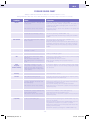
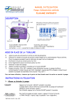
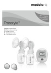
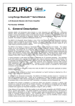
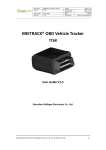
BE-NL DE-AT-CH-LU ES FR-BE-CH-LU IT-CH PT UK-IE INSTRUCTIONS FOR USE For enteral use onl Read this manual before using the pump ZMNL400336_AW.indd 2 3/18/10 3:47:27 PM BE-NL • INHOUD Algemene productinformatie Voorbereiding Service en garantie Gebruiksaanwizing Alarmfuncties en veiligheidsvoorzieningen Onderhoud Problemen en oplossingen Instelmodus Technische specificaties 5 5 5 6 10 10 11 12 14 DE-AT-CH-LU • INHALT Allgemeine Informationen Vorbereitung Service und Gewährleistung Bedienungsanweisung Alarmfunktionen und Sicherheitstechnik Instandhaltung Fehlersuchtabelle Sstemeinstellungen Technische Daten Bestellinformation 15 16 17 17 Introducción 27 Preparación 27 Servicio garantía 27 Instrucciones de funcionamiento 28 Funciones de alarma prestaciones de seguridad 32 Mantenimiento 32 Diagrama de solución de problemas 33 Modo de configuración 34 Especificaciones técnicas 36 FR-BE-CH-LU • CONTENT ZMNL400336_AW.indd 3 42 43 44 45 IT-CH • CONTENUTI Introduzione Preparazione Servizio e garanzia Istruzioni per l’uso Allarmi e funzioni di sicurezza Manutenzione Risoluzione dei problemi Funzione di parametrizzazione Specifiche tecniche 47 47 47 48 52 52 53 54 55 PT • ÍNDICE 22 22 23 24 25 26 ES • ÍNDICE Introduction Précautions d’emploi Service après-vente et garantie Instructions d’utilisation Alarmes et sécurités Entretien Résolutions des problèmes Mode de paramétrage Spécifications techniques 37 37 37 38 42 Introdução 57 Preparação 57 Serviço e garantia 57 Instruções de funcionamento 58 Funções do alarme e características de segurança 62 Manutenção 62 Quadro para soluções e problemas 63 Modo de configuração - Set up 64 Especificações técnicas 65 UK-IE • CONTENT Introduction 67 Preparation 67 Service and Warrant 67 Operating instructions 68 Alarm functions and safet features 72 Maintenance 72 Problem solver chart 73 Set up mode 74 Technical specifications 75 Appendix A: Guidance and manufacturer’s declaration Electromagnetic compatibilit 78 3/18/10 3:47:27 PM Figure 3 Figure 1 a h g d b Figure 4 f e c Figure 2 i Figure 5a k j Figure 5b Figure 5c Figure 5d B A ZMNL400336_AW.indd 4 3/18/10 3:47:31 PM BE-NL POMPSPECIFICATIES: Fig. 1: a Pompdeur b Scherm (LCD) c Toetsenbord d Rotor e Stroomopwaartse druksensor f Stroomafwaartse druksensor g Vake voor pompset h Luchtsensor Fig. 2: i Gebruiksaanwizing j Bevestigingspunt voor paalklem k Aansluiting voor adapter tema h Sensor del aire Fig. 2: i Instrucciones de uso j Receptáculo para el fiador del polo k Toma para la conexión a la unidad cargadora de enchufe Fig. 5a-5d: De pompset vullen en inbrengen DE-AT-CH-LU KOMPONENTENLISTE: Fig. 1: a Pumpentüre b Anzeigefeld (LCD) c Tastatur d Rotor e Vorgeschalteter Drucksensor f Nachgeschalteter Drucksensor g Anschluss für das Pumpsegment h Luftsensor Fig. 1: a Porta b Ecrã (LCD) c Teclado d Rotor e Sensor de pressão ascendente f Sensor de pressão descendente g Receptor para colocação do sistema h Sensor de ar Fig. 5a-5d: Inserción del equipo de bomba FR-BE-CH-LU LISTE DE COMPOSANTS: Fig. 1: a Porte b Ecran (LCD) c Clavier d Rotor e Capteur de pression amont f Capteur de pression aval g Site insertion cassette h Détecteur d’air Fig. 2: i Instructions d’utilisation j Site insertion support k Connexion de l’adaptateur IT-CH ELENCO DEI COMPONENTI: Fig. 4: AC/DC Adapter/Ladegerät Fig. 1: a Sportello pompa b Visualizzatore a cristalli liquidi (LCD) c Tastiera d Rotore e Sensore della pressione in ingresso f Sensore della pressione in uscita g Ricettacolo per l’inserto del set h Sensore dell’aria ZMNL400336_AW.indd 5 Fig. 2: i Instruções de utilização j Receptor para colocação do suporte k Conexão para o carregador Fig. 3: Suporte Fig. 4: Carregador Fig. 5a-5d: Colocação do sistema de alimentação na bomba Fig. 3: Support Fig. 3: Schraubhalterung Fig. 1: a Compuerta de la bomba b Panel indicador (LCD) c Teclado d Rotor e Sensor de presión ascendente f Sensor de presión descendente g Receptáculo para insertar el sis- Fig. 5a-5d: Inserimento del set Fig. 4: Cargador Fig. 4: Chargeur ES LISTA DE COMPONENTES: Fig. 4: Caricabatterie PT LISTA DE COMPONENTES: Fig. 2: i Bedienungshinweise j Anschluss für Schraubhalterung k Buchse für den Netzanschluss Fig. 5a-5d: Einführung des Pumpsegments Fig. 3: Sistema di fissaggio alla piantana Fig. 3: Fiador del polo Fig. 3: Paalklem Fig. 4: Adapter k Connettore per l’alimentatore Fig. 5a-5d: Insertion de la tubulure Fig. 2: i Istruzioni per l’uso j Ricettacolo per il sistema di fissaggio alla piantana UK-IE LIST OF COMPONENTS: Fig. 1: a Pump door b Displa panel (LCD) c Kepad d Rotor e Upstream pressure sensor f Downstream pressure sensor g Receptacle for pump insert h Air sensor Fig. 2: i Instructions for use j Receptacle for pole clamp k Socket for connection to the plug charger unit Fig. 3: Pole clamp Fig. 4: Charger Fig. 5a-5d: Filling and Insertion of the pump set 3/18/10 3:47:32 PM ORDERING INFORMATION Flocare® Infinit™ pump Western Europe corporate code 35676 Flocare® Infinit™ Charger Pole clamp Instructions for use Optional accessories Please refer to our local Nutricia contact for availabilit of Flocare® Infinit™ accessories, as there are: feeding sets, carr bag, PDMS/data cable, nurse call, service suitcase and other. MANUFACTURER Nutricia Medical Devices b.v. Schiphol Boulevard 261 1118 BH Schiphol Airport The Netherlands ZMNL400336_AW.indd 6 3/18/10 3:47:32 PM UK-IE INTRODUCTION • The Flocare® Infinit™ pump is a small, lightweight pump for both portable and bedside use. The pump is based on the rotar peristaltic principle and is intended for enteral use onl. PREPARATION • Check the integrit of the pump. Do not use the pump if it is damaged. If a technical failure occurs or if the pump is dropped, the pump should be checked b a qualified technician. • Do not use the pump in areas where there is a risk of explosions e.g. in the presence of flammable anaesthetics. • If the pump has been stored for an period of time, it should be plugged into the mains to recharge the batter before commencing enteral feeding. The batter will be completel charged after approximatel 6 hours. • The Flocare® Infinit™ pump should onl be used in combination with the appropriate Flocare® Infinit™ pump set! (consult our local Nutricia sales representative for information on availbale pump sets). • This pump operates in an orientation, making it ideal for ambulator use. • Check the position of the feeding tube, as advised b our healthcare professional, before commencing tube feeding. • Pump fed patients should be regularl monitored and supervised. Specific patient groups require consistent and controlled administration of enteral nutrition as well as simultaneous application of medication (e.g. insulin administration). In these cases, regular and frequent checks, as determined b the attending healthcare professional, should be carried out to ensure correct administration of nutrition throughout the therap period. Using the Infinit™ pump’s DOSE function is recommended in these cases (see section “To set a Dose”). • For bedside use, the multi-position pole clamp (figure 3) can be attached to the pump with the screw provided. The pump can be fixed in an position (rotatable in 360°). SERVICE AND WARRANTy The manufacturer recommends an inspection of the pump at an authorised service centre ever 2 ears. Onl authorised personnel should perform service work on Infinit™ pumps. Please contact our local Sales Organisation / Nutricia Subsidiar for all service and repair of pumps (see address at the back of the booklet). Limitations of warrant Solel for the benefit of the original buer/user, Nutricia Medical Devices B.V, warrants all new Flocare® Infinit™ pumps, of its manufacture to be free from defects in material and workmanship, excluding normal wear and tear, and will replace or repair, at its service facilit or other location designated b Nutricia Medical Devices B.V, an Flocare® Infinit™ pump returned to it within thirt-six (36) months of original purchase b the buer/user. Such repair or replacement shall be free of charge. Nutricia Medical Devices B.V warrants to the original buer/user, all repaired or replaced pumps to be free from defects in material and workmanship and will replace or repair such products, at its service facilit or other location designated b Nutricia Medical Devices B.V. Such repair or replacement shall carr a warrant of ninet (90) das from the date of repair or replacement or the balance of the new pumps warrant as described above, whichever is greater. THIS WARRANTy APPLIES ONLy TO FLOCARE® INFINITy™ PUMPS MANUFACTURED By NUTRICIA MEDICAL DEVICES B.V AND IS THE ONLy WARRANTy GIVEN WITH RESPECT TO THE PUMPS. NO WARRANTIES IMPLIED IN LAW, INCLUDING, BUT NOT LIMITED TO THE IMPLIED WARRANTIES OF MERCHANTABILITy AND FITNESS FOR PARTICULAR PURPOSE, SHALL APPLy. NUTRICIA MEDICAL DEVICES B.V WILL BE LIABLE, IN ANy EVENT, ONLy FOR THE PURCHASE PRICE OF THE DEFECTIVE PRODUCT, BUT NOT FOR ANy CONSEQUENTIAL DAMAGES. This Warrant ma not be modified, amended or otherwise changed, except b a written document properl executed b a corporate officer of Nutricia Medical Devices B.V THE WARRANTy IS VOID IF THE FLOCARE® INFINITy™ PUMP IS SUBjECT TO ABUSE, ACCIDENT, ALTERATION, MODIFICATION, TAMPERING, MISUSE OR THE UNAUTHORIZED REPAIR OR SERVICE IN ANy WAy WITHOUT PRIOR AUTHORIZATION FROM NUTRICIA MEDICAL DEVICES B.V. IN ANy EVENT, NUTRICIA MEDICAL DEVICES B.V.’S LIABILITy SHALL NEVER EXCEED THE ORIGINAL PURCHASE PRICE OF THE PUMP AND SHALL NOT EXTEND TO ANy CONSEQUENTIAL LOSS OR DAMAGE. -67- ZMNL400336_AW.indd 69 3/18/10 3:47:42 PM UK-IE OPERATING INSTRUCTIONS INSERTION OF THE FLOCARE® INFINITy™ PUMP SET • Connect the set to the feed container as instructed on the packaging of the Flocare® Infinit™ pump set. Remove the dust cap from the step connector. • The Flocare® Infinit™ pump sets are equipped with an “automatic free-flow protection”, as a consequence the set has no roller clamp. Fill the pump set completel with feed b gentl pinching on the side of the cassette that is marked with a drop (point A on figure 5a) or fill the pump set with help of the pump (see paragraph: filling the pump set). • Open the pump door b pressing up on the lower wall and rotating the door upwards at the same time (see figure 5b). • Position the looped section of the silicone tubing around the rotor. Stretching lightl, (see figure 5c) seat the cassette into the pump (see figure 5d). • Close the pump door. SWITCHING “ON” ON/OFF For proper pump operation, make sure the pump door is closed prior to switching the pump on. Press the “ON/OFF” ke for 2 seconds. The pump beeps and carries out a short self test, showing the pump serial number in 8 digits. Verif that all displa segments and smbols are active as shown in figure 6 (see next page). The pump displas the total volume delivered since the memor was cleared and switches in the hold mode read for programming. SWITCHING “OFF” ON/OFF Press the “ON/OFF” ke and keep it pressed for 2 seconds. A continuous alarm will be heard and the pump switches off. The feeding program (installed parameters) and total volume administered since the last clearance will be retained in the pump’s memor. If the pump shuts down due to low batter voltage, the memor will be retained for 24 hours. “HOLD” MODE START/STOP To temporaril pause the pump, or switch into “hold” mode whilst operating, press the “START/STOP” ke once. Three beeps are heard and the run smbol disappears. The programmed flow rate (ml/h), volume (DOSE=VOL) and the administered volume (ml) are retained. The “hold” mode is used to temporaril stop the flow of feed: • to change the feeding program (installed parameters), • to change the feed container, -68- ZMNL400336_AW.indd 70 3/18/10 3:47:42 PM UK-IE • to administer medication without switching the pump off, • to silence an alarm and correct problems. After 3 minutes a two tone audible alarm sounds and the message “PUSH STRT” appears in the displa. Press “START/STOP” to stop the alarm and to extend the hold mode b a further 3 minutes or press “START/ STOP” twice (3 beeps will be heard) to resume programmed settings. FILLING THE PUMP SET ON/OFF d FILL SET The FILL SET function offered b the Infinit pump is used to fill a (new) feeding set with nutrition (or water as the case ma be). When the FILL SET function runs all alarms are deactivated helping avoid alarms being inadvertentl triggered (e.g. air alarm). The FILL SET function should onl be used to fill an empt (air-filled) feeding set. Use of the FILL SET function at an other time ma cause the pump to incorrectl calibrate. When the FILL SET function is initiated the pump will calibrate to the giving set. When the pump is in the hold mode: Press and hold the “FILL SET” ke for 2 seconds to activate the “FILL SET” maneuver. Release the button as soon as the pump generates a beep and starts pumping at a flow rate of approx. 700ml/h. During this maneuver the message “FILL SET” appears in the displa. The pump will automaticall stop when the Flocare® Pack Infinit™ pump set is completel filled with feed. However this “FILL SET” maneuver can at antime be stopped b pushing the “FILL SET” ke a second time. The pump will return to the hold mode when the “FILL SET” maneuver is complete or stopped. DISPLAy The pump has a liquid crstal displa (L.C.D.) with large alphanumeric characters, smaller smbols, words and a back light. The following information can be found in the displa: • Flow rate (ml/h), volume (ml), is displaed through the large characters. Words below describe what the number relates to (rate, dose or volume). The pump also displas messages, for example “end of dose” will appear when the pump has finished delivering a single feed dose. •The arcs around the run smbol rotate when the pump is running. Figure 6 •The remaining batter capacit (see paragraph: batter operation). •The wall plug smbol indicates that the charger is plugged in. The back light of the displa turns off 10 seconds after the last ke is pressed. The back light will switch on for 10 seconds when the charger is connected to the mains. -69- ZMNL400336_AW.indd 71 3/18/10 3:47:42 PM UK-IE PROGRAMMING THE PUMP • The Flocare® Infinit™ pump can be used for continuous or dose feeding. • Insert the pump set in the pump, switch the pump on and fill the pump set when necessar (see paragraph: filling the pump set). • The displa shows the total volume delivered since the pump was last cleared. • If necessar clear the volume delivered b pressing the “CLR” ke. • The last installed flow rate (ml/h) is now displaed. • The pump is now in the “hold” mode and is read for programming. CONTINUOUS FEEDING ON/OFF d ml/h d +- 400 ml/h 1 ml/h d START/STOP • Adust the flow rate (ml/h) if required b using the “+” or “-” ke. Hold either ke down to change rapidl. • If another parameter is indicated in the LCD, it will be necessar to first press the “ml/h” ke followed b the “+” or “-” ke to set the flow rate. • The flow rate ranges from 1 - 400 ml/h in 1ml increments. • The flow rate slows down and stops shortl at 50 - 125 - 250 ml/h. • Press the “DOSE=VOL” ke and make sure the value is put at 0 ml indicated b the word “CONT”. This means the pump will run in a continuous mode. • Start the pump b pressing “START/STOP”. • The arcs around the word “run” start rotating. • The flow rate (ml/h) is displaed whilst functioning. TO SET A DOSE ON/OFF d ml/h d +- 400 ml/h 1 ml/h d DOSE=VOL d +- 4000 ml 1 ml d START/STOP From the hold mode, with the last flow rate (ml/h) displaed in the LCD: • Set the flow rate b pressing the “+” or “-” ke. If another parameter is displaed: • Press first the “ml/h” ke followed b “+” or “-” ke to adust the flow rate. The flow rate can be set between 1 and 400 ml/h, with increments of 1ml. • Press the “DOSE=VOL” ke and install the volume to be administered with the “+” and “-” ke. The range goes from 1 - 4000 ml, with steps from 1ml. • Start the pump b pressing “START/STOP”. During functioning the following parameters can be found in the displa: • B pressing the “ml/h” ke the “flow rate” is displaed. • B pressing the “INFO” ke the total volume since the memor was cleared will be INFO visualized. When the required volume or dose has been delivered, “END OF DOSE” will appear and the pump will beep (or mute, depending upon the pumps’ configuration (see paragraph: set up mode). -70- ZMNL400336_AW.indd 72 3/18/10 3:47:43 PM UK-IE TO CHANGE THE FEEDING PROGRAM DURING FUNCTIONING • Press the “START/STOP” ke to pause the pump. • Change the program b pressing the required ke (ml/h or DOSE=VOL) and adust using the “+” or “-” kes. • Restart the pump b pressing the “START/STOP” ke again. CLEARING THE MEMORy d All parameters and values can be cleared one after the other in the following wa: • Press “START/STOP” to pause the pump. • Select the parameter that needs to be cleared. • Press the “CLR” ke to clear the memor. The parameter or value returns to its default value: ml/h = 0 ml/h VOL = cont = No dose set. Pump will feed continuousl until feed container is empt or pump is stopped INFO = 0 ml = Volume delivered is cleared In order to keep a clear overview of the dail amount of feed delivered, clear the total volume delivered as each dail feeding schedule is started, as follows: • Switch the pump “ON” START/STOP • Immediatel after the self-test the pump displas total volume delivered. • Press the “CLR” ke. The total volume delivered returns to “0 ml”. • The pump displas the previous programmed flow rate (ml/h). CLR • The pump is in the “HOLD” mode read for programming. • When another feeding program needs to be started, or the pump will be used for another patient, all settings (rate and dose) can be returned to default and the volume delivered can be set at zero b simpl pressing the “CLR” ke and keeping it pressed for 2 seconds. BATTERy OPERATION • The Flocare® Infinit™ pump is equipped with a Lithium-ion batter. • The batter smbol in the displa is automaticall replaced b the plug smbol when the adapter is plugged in. The “fuel gauge” then indicates that the batter is charging b displaing the segments in an ascending low to high pattern starting with the leftmost segment. This pattern continuousl repeats while the pump is charging. • To check the status of the batter, disconnect the charger from the pump and turn the pump on. The bars between E and F (E=Empt, F=Full) represent the “fuel gauge” of the batter. Each bar is approximatel 1/4 of a full batter charge. If 2 bars appear the batter is half full and remaining operating time is approximatel 12 hours at a flow rate of 125 ml/h. • In case of power failure the pump automaticall switches to batter powered operation. • When during functioning the last block is gone, the batter smbol will blink to indicate that there is approximatel 1 hour of charge left. The displa will flash “BATT” ever 3 seconds, alternating with the active displa and the pump will beep ever 2 seconds to remind the user of the low batter charge condition. Plug in the charger to continue to run and recharge the batter. • As the batter level decreases the pump ma not be able to deliver tube feeds at rates greater than 300 ml/h, even though some batter capacit remains. The pump will alarm and indicate “BATT”. If this happens, either -71- ZMNL400336_AW.indd 73 3/18/10 3:47:43 PM UK-IE recharge the batter or select a lower rate to complete the feed ccle. • In case of batter failure, caused b, for example, an excessive temperature condition (which ma resolve itself with time) or b a complete batter failure, the E, F and batter smbol will flash. Turn the pump “off” and contact our healthcare provider or refer the pump to service. CONNECTION TO AN EXTERNAL ALARM SySTEM The power connector at the side of the pump offers the option of connecting the pump to an external alarm sstem or Patient Data Monitoring Sstem (PDMS). • The Flocare® Infinit™ Nurse Call (corporate code 35752) enables connection to an external alarm sstem. This external alarm sstem ma be with open or closed contact. Follow the instructions for use of the Flocare® Infinit™ Nurse Call to connect the pump. • The Flocare® Infinit™ PDMS Cable (corporate code 35776) enables connection to an external PDMS sstem. Follow the instructions for use of the Flocare® Infinit™ PDMS Cable to connect the pump. ALARM FUNCTIONS AND SAFETy FEATURES In case an of the problems listed on the problem solver chart occur, the pump delivers an audible and visual alarm and stops working. The back light of the LCD automaticall switches on. Exception to this is the low batter alarm “BATT”, in this situation the pump continues working. Action in the event of an alarm: Check the tpe of alarm displaed b the large displa characters. • Press the “START/STOP” ke to stop the audible and visual alarm. • Correct the cause of the alarm as described in the table. • Start the pump again b pressing “START/STOP”. The problem solver chart on the next page gives a clear explanation of the alarms. MAINTENANCE Cleaning: • Alwas unplug the pump prior to cleaning to avoid electric shock hazard. • On a regular basis thoroughl clean all surfaces of the pump (including the sensors and rotor) with warm soap water, a 5% bleach solution in water, or a multipurpose disinfectant cleaner. • The Flocare® Infinit™ pump ma be rinsed b holding under a stream of warm, clean water. Do not submerge the pump! • Alwas maintain the rollers on the rotor in a clean state to ensure the spin freel. • The adaptor normall does not require cleaning. When desired, a dr or slightl damp cloth ma be used to clean the outside surface of the adaptor. Make sure the adaptor is disconnected from the wall outlet. Safet notes: • The manufacturer recommends an inspection of the pump at an authorised service centre ever 2 ears. • If an fault occurs during use, or if the pump is dropped, it should be checked b authorised technical personnel prior to use. • Replace the Flocare® Infinit™ pump set ever 24 hours to maintain deliver accurac and prevent the growth of harmful bacteria. Dispose of Flocare® Infinit™ disposable sets properl, as required b local law. • Do not use the Infinit alarm sstems to trigger actions related to secondar (electrical) medical devices (e.g. a volumetric or sringe pump). • Do not use pump functions (e.g. the fill set function) for an other purpose than described in this manual, as this ma cause the pump to incorrectl calibrate. -72- ZMNL400336_AW.indd 74 3/18/10 3:47:43 PM UK-IE PROBLEM SOLVER CHART Alwas follow the instructions below in case a problem occurs. Using methods other than those described ma cause the pump to function incorrectl. Condition NO SET PUSH STRT END OF DOSE Cause Correction • The set is not fitted or wrongl fitted • Stop the alarm b pressing “START/STOP” in the pump. • Insert the Flocare® Infinit™ cassette into the pump as indicated on the blister packaging and close the door. • Restart the pump. • Clean the sensors, reinsert the cassette in the pump and • The pressure sensor area is dirt restart the pump. • The pump has been untouched in hold mode for 3 minutes or more. • Stop the alarm and prolong the hold mode with another 3 minutes b pressing “START/STOP” ke. • Program the pump and start it b pressing the “START/ STOP”. • The pump administered the installed • Turn the pump off b pressing the “ON/OFF” ke dose = volume. and hold it during 2 seconds or • Clear the memor of the total volume administered (see paragraph: clearing the memor), reprogram a new feeding schedule and start the pump b pressing “START/ STOP”. PROG • No flow rate is installed. Flow rate = 0 ml/h • Make sure the correct flow rate is programmed. DOOR • The door is not correctl closed. • Make sure the door is properl closed prior to starting a feeding program. AIR • The air sensor detected an empt pump set. • The air sensor area is dirt. • The feeding set is not inserted correctl. • Replace the empt feeding reservoir and continue feeding. If necessar prime the set. • Make sure the air sensor is clean. • Make sure the feeding set is properl inserted in the pump. BATT the pump remains working • The batter capacit is too low. The pump is not able to deliver highl viscous fluids at high flow rates with the present charge level of the batter. • Connect the adaptor to the pump and mains and charge the pump for approx. 6 hours. During charging the pump can be used. • Batter failure. • Turn the pump “off”, contact our healthcare provider or refer the pump to service. FILL SET • The pump is priming the set. • Press the “FILL SET” ke another time to stop the pump and bring it back in the hold mode. OCC IN • The pump detected an upstream occlusion between the pump and the feeding bag. • Stop the alarm b pressing the “START/STOP” ke. • Remove the feeding set out of the pump and check the permeabilit b flushing the line. • Re-insert the feeding set in the pump and restart. • Clean the sensors, reinsert the cassette in the pump and restart the pump. Batter, “E” and “F” flashing • The pressure sensor area is dirt. OCC OUT OCC OUT (repeated) • The pump detected a downstream occlusion between the pump and the patient. • The pressure sensor area is dirt. • Stop the alarm b pressing the “START/STOP” ke. • Check the permeabilit of the feeding tube b aspirating liquid via the medication port. • Clean the sensors, reinsert the cassette in the pump and restart the pump. • Calibration not et completed on the current feeding set • Stop the alarm b pressing the “START/STOP” ke. • Start the pump b pressing the “START/STOP” ke and let it run onl briefl. • Stop the pump b pressing the “START/STOP” ke insuring that there has been no occlusion out alarm. • Remove the feeding set from the pump and reinsert the feeding set in the pump. • Restart the pump b pressing the “START/STOP” ke. -73- ZMNL400336_AW.indd 75 3/18/10 3:47:43 PM UK-IE Condition Cause Correction LOCK • Onl the current feeding schedule is allowed for this patient. Another feeding program is not allowed b our healthcare professional. • The programming feature is blocked in the set up mode of the pump. Ask our healthcare professional to modif this setting. ER01 - ER99 • The self test detected an electronic error • Turn the pump “off”, make sure the pump door is closed and switch the pump back “on”. If the error persists, contact our healthcare provider or refer the pump to service. No plug smbol visi- • The wall outlet doesn’t work. ble, while the pump • The adaptor is damaged. is connected to the mains. • Connect the pump to another wall outlet. • Contact our healthcare professional or Nutricia subsidiar to replace the adaptor. SET UP MODE The set up mode is used • • • • • to set the alarm level, to lock the kepad, to switch the audible alarm off when a dose is administered, to switch the light of the LCD permanentl on when connected to the mains, to enable connection with a Nurse call or Patient Data Monitoring Sstem (PDMS). This set up mode ma onl be entered b healthcare professionals and authorised personnel trained to use this application of the pump. The patient or his/her relatives without permission of the phsician, dietician, nurse or other licensed practitioner, ma not change the settings of the set up mode. TO SET THE ALARM LEVEL ON/OFF & 2 sec + 2 sec d + - Beep high Beep low Switch the pump “on” while holding the “+” ke down. The pump enters the set up mode. First the alarm level can be set: “BEEP HIGH” (+) or “BEEP LOW” (-) Use the “+” or “-” ke to change the setting from “high” to “low” or from “low” to “high”. TO LOCK THE KEyPAD FILL SET d + - Lock Unlk Press in the set up mode the “FILL SET” ke to switch to the next setting: “UNLK” the kepad (-) or “LOCK” the kepad (+). In the “LOCK” mode the feeding program of the pump can no longer be changed. Use the “+” or “-” ke to change the setting from “lock” to “unlk” or vice versa. -74- ZMNL400336_AW.indd 76 3/18/10 3:47:43 PM UK-IE TO MUTE WHEN DOSE DONE FILL SET d + - Beep when done Mute when done Press in the set up mode the “FILL SET” ke to switch to the next setting: “BEEP WHEN DONE” (+): the pump will give an alarm when the dose is administered or “MUTE WHEN DONE” (-): the pump will not give an alarm after administering the dose. Use the “+” or “-” ke to change the setting from “beep when done” to “mute when done” or vice versa. TO SWITCH LIGHT ON FILL SET d + - Lite on Lite off d ON/OFF 2 sec Press in the set up mode the “FILL SET” ke to switch to the next setting: “LITE ON” (+) the light of the LCD remains on when the pump is connected to the mains. “LITE OFF” (-) the light of the LCD switches off after a few seconds even if connected to the mains. Use the “+” or “-” ke to change the setting from “lite on” to “lite off” or vice versa. TO CONNECT WITH NURSE CALL OR PDMS FILL SET d + - OUTP PDMS OUTP NRSE d ON/OFF 2 sec Press in the set up mode the “FILL SET” ke to switch to the next setting: “OUTP PDMS” (+) to connect with a Patient Data Monitoring Sstem. “OUTP NRSE” to connect with a NURSE CALL sstem. Use the “+” or “-” ke to change to setting from “OUTP PDMS”, to “OUTP NRSE” or “OUTP OFF” and vice versa. Press the “ON/OFF” ke and hold it down for 2 seconds to exit the SET UP mode. The settings are automaticall saved. TECHNICAL SPECIFICATIONS • This Flocare® Infinit™ pump in combination with the adapter and the Flocare® Infinit™ Nurse Call are designed to EN 60601-1-2, EN 61000-3-2, EN 61000-3-3, RTCA DO-160D standards for electromagnetic emissions and immunit and are in compliance with Directive 93/42/EEC. 0344 • IEC 601: Class II Medical Device Directive: Class IIa • Microprocessor controlled • BF Equipment • Charger: input 100-240V AC / 50-60 Hz / 0.4A Max. output 5 V DC 2.4 A • Batter: internal rechargeable Lithium ion batter, 3.6 V DC 2000 mAh • Batter capacit: 24 hours at 125 ml/h • jet waterproof: IPX 5 • IPX 5: Splash water proof: Water ets from an direction shall have no effect on the pump. -75- ZMNL400336_AW.indd 77 3/18/10 3:47:43 PM UK-IE • Dimensions: 140 x 95 x 35 mm • Weight: approx. 392 g • Accurac flow rate: ±5,0% with appropriate Flocare® Infinit™ pump set • Humidit: Operation mode: 30% to 75% noncondensing Storage: 10% to 95 % noncondensing • Temperature: Operation mode: +5°C to +40°C Storage and transportation: -20°C to +65°C • Atmospheric pressure: Operation mode: 70-106 kPa Storage and transportation: 50-106 kPa • Occlusion detection pressure: Upstream occlusion: -34 kPa (tolerance 21 kPa) Downstream occlusion: 83 kPa (tolerane 21 kPa) • Air bubble detection: The amount of air, that must pass the air sensor before the air alarm is activated, varies from 0.5 to 1 ml which relates to an air bubble with an approximate length in the silicone pump segment of 6 - 13 cm. • The Flocare® Infinit™ can safel be operated on commercial aircraft. • The use of other accessories, adaptors and cables than listed within this manual ma result in increased emissions or decreased immunit of the equipment of the Flocare® Infinit™ pump. • Medical electrical equipment needs special precautions regarding EMC and needs to be installed and put into service according to the EMC information provided in the accompaning documents. • Portable and mobile RF communications equipment (cellular telephones) can affect medical electrical equipment. If the Flocare® Infinit™ pump is used adacent to or stacked with other equipment, the pump should be observed to verif normal operation. • In case of pump scrapping, alwas notif our Nutricia sales unit of the pumps serial number. Pump scrapping should alwas occur according to local legislation. -76- ZMNL400336_AW.indd 78 3/18/10 3:47:43 PM -77- ZMNL400336_AW.indd 79 3/18/10 3:47:43 PM APPENDIX A: GUIDANCE AND MANUFACTURER’S DECLARATION ELECTROMAGNETIC COMPATIBILITy Guidance and manufacturer’s Declaration – Electromagnetic emissions ® The Flocare Infinit™ enteral feeding pump is intended for use in the electromagnetic environment specified below. The customer or the user of the Flocare® Infinit™ enteral feeding pump should assure that it is used in such an environment. Emissions test Compliance Electromagnetic environment – guidance RF Emissions CISPR 11 Group 1 The Flocare® Infinit™ uses RF energ onl for its internal function. Therefore, its RF emissions are ver low and are not likel to cause an interference in nearb electronic equipment. RF Emissions CISPR 11 Class B Harmonic emissions IEC 61000-3-2 Class A The Flocare® Infinit™ is suitable for use in all establishments, including domestic establishments and those directl connected to the public low-voltage power suppl network that supplies buildings used for domestic purposes. Voltage fluctuations/ Flicker emissions IEC 61000-3-3 Complies Guidance and manufacturer’s Declaration – Electromagnetic immunit ® ™ The Flocare Infinit enteral feeding pump is intended for use in the electromagnetic environment specified below. The customer or the user of the Flocare® Infinit™ enteral feeding pump should assure that it is used in such an environment. Immunit test IEC 60601 test level Compliance level Electromagnetic environment – guidance Electrostatic discharge (ESD) IEC 61000-4-2 ≤ 6 KV contact ≤ 6 KV contact ≤ 8 KV air ≤ 8 KV air Floors should be wood, concrete or ceramic tile. If floors are covered with snthetic material, the relative humidit should be at least 30%. Electric fast transient/burst IEC 61000-4-4 ≤ 2 KV for power suppl lines ≤ 1 KV for input/ output lines ≤ 2 KV for power suppl lines ≤ 1 KV for input/ output lines Mains power qualit should be that of a tpical commercial or hospital environment. Surge IEC 61000-4-5 ≤ 1 KV differential mode ≤ 1 KV differential mode Mains power qualit should be that of a tpical commercial or hospital environment. Voltage dips, short interruptions and voltage variations on power suppl lines. IEC 61000-4-6 161 Vac for 0,5 s 95 Vac for 100 ms 0 Vac for 10 ms 0 Vac for 5 s 161 Vac for 0,5 s 95 Vac for 100 ms 0 Vac for 10 ms 0 Vac for 5 s Mains power qualit should be that of a tpical commercial or hospital environment. If the user of the Flocare® Infinit™ requires continued operation during power mains interruptions, it is recommended that the Flocare® Infinit™ enteral feeding pump be powered from an uninterruptible power suppl of batter. -78- ZMNL400336_AW.indd 80 3/18/10 3:47:44 PM Recommended separation distances between portable and mobile RF communications euipment and the Flocare® Infinit™ enteral feeding pump The Flocare® Infinit™ enteral feeding pump is intended for use in an electromagnetic environment in which radiated RF disturbances are controlled. The customer or the user of the Flocare® Infinit™ can help prevent electromagnetic interference b maintaining a minimum distance between portable and mobile RF communications equipment (transmitters) and the Flocare® Infinit™ as recommended below, according to the maximum output power of the communications equipment. Rated Maximum output power of transmitter (W) Separation distance according to frequenc of transmitter (m) 150 KHz to 80 MHz 80 MHz to 800 MHz 800 MHz to 2,5 GHz d = 0,12CDP d = 0,12CDP d = 0,23CDP 0,01 0,01 0,01 0,02 0,1 0,04 0,04 0,07 1 0,12 0,12 0,23 10 0,37 0,37 0,74 100 1,17 1,17 2,33 For transmitters rated at a maximum output power not listed above, the recommended separation distance d in metres (m) can be estimated using the equation applicable to the frequenc of the transmitter, where P is the maximum output power rating of the transmitter in Watts (W) according to the transmitter manufacturer. NOTE 1 NOTE 2 At 80 MHz and 800 MHz, the separation distance for the higher frequenc range applies. These guidelines ma not appl in all situations. Electromagnetic propagation is affected b absorption and reflection from structures, obects and people. Guidance and manufacturer’s Declaration – Electromagnetic immunit The Flocare® Infinit™ enteral feeding pump is intended for use in the electromagnetic environment specified below. The customer or the user of the Flocare® Infinit™ enteral feeding pump should assure that it is used in such an environment. Immunit test IEC 60601 test level Compliance level Electromagnetic environment – guidance Portable and mobile RF communications equipment should be used no closer to an part of the Flocare® Infinit™, including cables, than the recommended separation distance calculated from the equation applicable toe the frequenc of the transmitter: Recommended separation distance Conducted RF IEC 61000-4-6 Radiated RF IEC 61000-4-3 3 Vrms 150 KHz to 80 MHz 3 V/m 80 Mhz to 2,5 GHz 3 Vrms 150 KHz to 80 MHz 30 V/m 80 Mhz to 2,5 GHz d = 1,17CDP d = 0,12CDP 80 MHz to 800 MHz d = 0,23CDP 800 MHz to 2,5 GHz Where P is the maximum output power rating of the transmitter in watts (W) according to the transmitter manufacturer and d is the recommended separation distance in metres (m). Field strengths from fixed RF transmitters, as determined b an electromagnetic site surve,a should be less than the compliance level in each frequenc range.b Interference ma occur in the vicinit of equipment marked with the following smbol: NOTE 1 NOTE 2 At 80 Mhz and 800 MHz, the higher frequenc range applies. These guidelines ma not appl in all situations. Electromagnetic propagation is affected b absorption and reflection from structures, obects and people. a. Field strengths from fixed transmitters, such as base stations for radio (cellular/cordless) telephones and land mobile radios, amateur radio, AM and FM radio broadcast and TV broadcast cannot be predicted theoreticall with accurac. To assess the electromagnetic environment due to fixed RF transmitters, an electromagnetic site surve should be considered. If the measurement field strength in the location in which the Flocare® Infinit™ is used exceeds the applicable RF compliance above, the Flocare® Infinit™ should be observed to verif normal operation. If abnormal performance is observed, additional measures ma be necessar, such as reorienting or relocating the Flocare® Infinit™. b. Over the frequenc range 150 KHz to 80 MHz, field strengths should be less than 3 V/m. -79- ZMNL400336_AW.indd 81 3/18/10 3:47:44 PM -80- ZMNL400336_AW.indd 82 3/18/10 3:47:44 PM