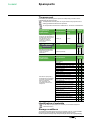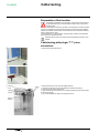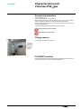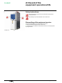
1
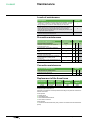
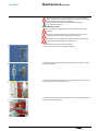
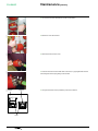
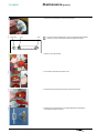
Medium Voltage Distribution
FLUSARC
36 kV - 630 A - 25 kA
Operation - Maintenance
Instructions
www.schneider-electric.com
FLUSARC
Contents
■■ Introduction��������������������������������������������������������������������������������������������������������� 3
□□ Our Service Unit: our specialists, and suitably adapted services������������������ 3
■■ Overview�������������������������������������������������������������������������������������������������������������� 4
□□ Responsibilities���������������������������������������������������������������������������������������������� 4
□□ Particular instructions for operations and interventions on energized equipment4
□□ Other technical notices to be consulted��������������������������������������������������������� 4
□□ Tools (not supplied) required for the operations described in this user manual��� 4
□□ Symbols & conventions���������������������������������������������������������������������������������� 4
■■ Functional Interlocks����������������������������������������������������������������������������������������� 5
□□ Functional mechanical interlocks������������������������������������������������������������������� 5
□□ Interlocks for functions C and T1������������������������������������������������������������������� 5
□□ Interlocks for function CB������������������������������������������������������������������������������� 5
■■ Operating accessories��������������������������������������������������������������������������������������� 6
□□ Reminder for Manual Operations������������������������������������������������������������������� 6
□□ Operating accessories����������������������������������������������������������������������������������� 6
□□ Key locks (optional)���������������������������������������������������������������������������������������� 6
■■ Use of the C function����������������������������������������������������������������������������������������� 7
□□ Opening the earthing switch�������������������������������������������������������������������������� 7
□□ Closing the earthing switch���������������������������������������������������������������������������� 7
□□ Closing the switch disconnector��������������������������������������������������������������������� 8
□□ Opening the switch disconnector������������������������������������������������������������������� 8
■■ Use of the CB function�������������������������������������������������������������������������������������� 9
□□ Opening the earthing switch�������������������������������������������������������������������������� 9
□□ Closing the earthing switch���������������������������������������������������������������������������� 9
□□ Closing the disconnector������������������������������������������������������������������������������ 10
□□ Opening the disconnector���������������������������������������������������������������������������� 10
□□ Closing the circuit breaker����������������������������������������������������������������������������11
□□ Open the circuit breaker��������������������������������������������������������������������������������11
■■ Use of the T1 function������������������������������������������������������������������������������������� 12
□□ Opening the earthing switch������������������������������������������������������������������������ 12
□□ Closing the earthing switch�������������������������������������������������������������������������� 12
□□ Closing the switch disconnector������������������������������������������������������������������� 13
□□ Opening the switch disconnector����������������������������������������������������������������� 13
■■ Maintenance������������������������������������������������������������������������������������������������������ 14
□□ Levels of maintenance��������������������������������������������������������������������������������� 14
□□ Preventive maintenance������������������������������������������������������������������������������� 14
□□ Corrective maintenance������������������������������������������������������������������������������� 14
□□ Replacement of the three fuses������������������������������������������������������������������� 14
□□ Replacement of a fuse��������������������������������������������������������������������������������� 15
□□ Replacement of a signal lamp assembly����������������������������������������������������� 18
■■ Spare parts�������������������������������������������������������������������������������������������������������� 19
□□ The spare part���������������������������������������������������������������������������������������������� 19
□□ Identification of materials����������������������������������������������������������������������������� 19
□□ Storage conditions��������������������������������������������������������������������������������������� 19
■■ Cable testing����������������������������������������������������������������������������������������������������� 20
□□ Preparation of the function��������������������������������������������������������������������������� 20
□□ Cable testing with plugin ”T1” piece connectors������������������������������������������ 20
■■ Characteristics and Volumes of SF6 gas�������������������������������������������������������� 21
□□ General characteristics�������������������������������������������������������������������������������� 21
□□ Filling pressure��������������������������������������������������������������������������������������������� 21
□□ FLUSARC functions������������������������������������������������������������������������������������� 21
■■ At the end of the equipment operational life������������������������������������������������� 22
□□ Safety instructions���������������������������������������������������������������������������������������� 22
□□ Dismantling of the equipment service���������������������������������������������������������� 22
■■ Notes������������������������������������������������������������������������������������������������������������������ 23
2
Products-L4AS-FLUSARC_36-71911-V1-EN
FLUSARC
Introduction
Operations and maintenance may only be carried out by personnel who have
received suitable authorisation for the operations and manœuvres they are
responsible for performing.
If this is not the case, please refer to our Service Unit or Training Centre.
All locking−out operations must be performed according to the safety regulations
currently being in force.
KJA8300
Our Service Unit: our specialists, and
suitably adapted services
■■ Guarantee extension contracts in relation to the selling of new equipment,
■■ Supervision of HVA switchgear installations,
■■ Technical advice, diagnoses of the facilities, expertise,
■■ Maintenance contracts adapted to operational constraints,
■■ Systematic or conditional preventive maintenance,
■■ Corrective maintenance in case of partial or complete failure,
■■ Supply of spare parts.
Contact the Service Unit for diagnoses and advice:
Working hours
Phone No: +39 0377 417 351 7 office hours
Fax: +39 0377 451133
Products-L4AS-FLUSARC_36-71911-V1-EN
3
FLUSARC
Overview
© − Schneider Electric− 2010. Schneider Electric, the Schneider Electric logo and
their figurative forms are Schneider Electric registered trademarks.
The other brand names mentioned within this document, whether they be copyright
or not, belong to their respective holders.
Responsibilities
Our devices are quality controlled and tested at the factory in accordance with the
standards and the regulations currently in force.
Apparatus efficiency and apparatus life depend on the compliance with the
installation, commissioning and operation instructions described in this user manual.
Non respect of these instructions is likely to invalidate any guarantee.
Local requirements especially about safety and which are in accordance with the
indications given in this document, must be observed.
Schneider Electric declines any responsibility for the consequences:
■■ due to the non respect of the recommendations in this manual which make
reference to the international regulations in force.
■■ due to the non respect of the instructions by the suppliers of cables and
connection accessories during installation and fitting operations,
■■ of any possible aggressive climatic conditions (humidity, pollution, etc.) acting in
the immediate environment of the materials that are neither suitably adapted nor
protected for these effects.
This user manual does not list the locking−out procedures that must be applied. The
interventions described are carried out on de−energized equipment (in the course of
being installed) or locked out (non operational).
Particular instructions for operations and
interventions on energized equipment
When commissioning and operating the equipment under normal conditions, the
General safety instructions for electrical applications must be respected, (protective
gloves, insulating stool, etc.), in addition to standard operating instructions.
All manipulations must be completed once started.
The durations (for completing the operations mentioned) given in the maintenance
tables are purely an indication and depend on on−site conditions.
Other technical notices to be consulted
■■ Products-L4-Flusarc-71897-V1-EN - Technical Characteristics
Tools (not supplied) required for the
operations described in this user manual
■■ Flat, thin screwdriver (4) + medium
■■ Leather gloves
Symbols & conventions
06
Code for a product recommended and marketed by Schneider Electric
Tightening torque value.
Example: 1.6 daN.m
Mark corresponding to a key
Caution! Remain vigilant!
Precautions to be taken in order to avoid accidents or injury
Forbidden! Do not do it!
Compliance with this indication is compulsory, non compliance
withthisstipulation may damage the equipment.
Information − Advice
Your attention is drawn to a specific point or operation.
4
Products-L4AS-FLUSARC_36-71911-V1-EN
Functional Interlocks
FLUSARC
Functional mechanical interlocks
The FLUSARC switchgear is equipped with internal mechanical interlocks, called ”functional”, intended to avoid any kind of operating error.
It is necessary to know these interlocks in order to operate the switchgear correctly.
Interlocks for functions C and T1
Position
Switch
disconnector
Earthing switch
Access to fuses
or cables compartment
Switch disconnector
Closed
Open
−
−
Locked open
Free
Not allowed
Dependant on the position of the
earthing switch
Earthing switch
Closed
Open
Locked open
Free
−
−
Free
Locked closed
Access to fuses
Open
Locked open
Locked closed
Access to cables
compartment
Open
Locked open
■■ Free for C function
■■ Locked / closed
for T1 function
−
−
Interlocks for function CB
Circuit
breaker
Position
Closed
−
Circuit breaker
Disconnector
Earthing switch
Locked
(in closed position)
Access cover to
cables compartment
Locked open
Not allowed
Dependant on the position of the
earthing switch
Open
−
Free
Dependant on the position of the
disconnector
Closed
Free
−
Locked open
Not allowed
Open
Open
−
Free
Dependant on the position of the
earthing switch
Closed
Open
Locked open
−
Free
Open
Dependant on the
position of the
disconnector
Free
−
Not allowed
Open
Open
Locked open
Free
−
Disconnector
Earthing switch
Access panel to
the cable
compartment
Products-L4AS-FLUSARC_36-71911-V1-EN
5
Operating accessories
FLUSARC
Reminder for Manual Operations
KJA0300
All movements of the lever must be frank and complete.
KJA0400
Circuit breaker closing spring loading
lever (CB unit)
Operating lever
KJA0700
Closed earth free key
(transformer protection unit)
Open earth free key
(line unit and transformer
protection unit)
6
KJA0600
They are used, in order to prevent any possible wrong operations during the
FLUSARC switchgears use.
Closed earth free key
(line unit)
KJA0800
KJA0500
Key locks (optional)
Open line free key
(line unit and transformer
protection unit)
Products-L4AS-FLUSARC_36-71911-V1-EN
KJB28KK
FLUSARC
Use of the C function
The procedures here following described refer to a line switchgear with
manual closing and opening controls. Should those controls be electric and
remotely controlled, it will be necessary to shift the interlock on the
disconnector control operation, in order to insert the lever, and, if the remote control
is present, it will be necessary to act on the relevant selector, in order to enable the
operation on place.
■■ Disconnector control operation interlock device
KJA85KK
KJA8400
Opening the earthing switch
■■ Insert the operating lever into the earthing switch control.
■■ Grasp the lever with both hands.
■■ Turn the lever counter clockwise, up to reach the end of stroke. The mimic diagram
indicator will turn from the closed earth position
to the open earth position
■■ Extract the operating lever.
Closing the earthing switch
KJA8700
KJA86KK
Before closing the earthing switch, ensure there is no voltage across the
voltage presence signal lamp.
Products-L4AS-FLUSARC_36-71911-V1-EN
■■ Act on the interlock, by shifting it upwards
■■ Insert the operating lever into the earthing switch control.
7
KJA88KK
FLUSARC
Use of the C function (contd.)
■■ Turn the lever clockwise, up to reach the end of stroke. The mimic diagram
indicator will turn from the open earth position to
the closed earth position
■■ Extract the operating lever.
KJA91KK
KJA9000
KJA89KK
Closing the switch disconnector
■■ Act on the interlock, by shifting it downwards
■■ Insert the operating lever into the switch disconnector control.
■■ Turn the lever clockwise, up to reach the end of stroke. The mimic diagram
indicator will turn from the open line position
to the closed line position
■■ Extract the operating lever.
KJA93KK
KJA9200
Opening the switch disconnector
8
■■ Insert the operating lever into the switch disconnector control.
■■ Grasp the lever with both hands.
■■ Turn the lever counter clockwise, up to reach the end of stroke. The mimic diagram
indicator will turn from the closed line position
to the open line position
■■ Extract the operating lever.
Products-L4AS-FLUSARC_36-71911-V1-EN
FLUSARC
Use of the CB function
The procedures here following reported refer to a line switchgear with manual
closing and opening controls. Should those controls be electric and remotely
controlled, it will be necessary to act on the relevant selector, in order to
enable the operation on place.
KJB12KK
KJB1100
Opening the earthing switch
■■ Insert the operating lever into the earthing switch control.
■■ Grasp the lever with both hands.
■■ Turn the lever counter clockwise, up to reach the end of stroke. The mimic diagram
indicator will turn from the closed earth position
to the earth and line open
position .
■■ Extract the operating lever.
Closing the earthing switch
KJB15KK
KJB1400
KJB13KK
Before closing the earthing switch, ensure there is no voltage across the
voltage presence signal lamp.
■■ Act on the interlock, by shifting it upwards.
■■ Insert the operating lever into the earthing switch control.
■■ Grasp the lever with both hands.
■■ Turn the lever clockwise, up to reach the end of stroke. The mimic diagram
indicator will turn from the earth and line open position
to the closed earth
position
.
■■ Extract the operating lever.
Products-L4AS-FLUSARC_36-71911-V1-EN
9
FLUSARC
Use of the CB function (contd.)
KJB18KK
KJB1700
KJB16KK
Closing the disconnector
■■ Act on the interlock, by shifting it downwards.
■■ Insert the operating lever into the disconnector control.
■■ Grasp the lever with both hands.
■■ Turn the lever clockwise, up to reach the end of stroke. The mimic diagram indicator
will turn from the earth and line open position
to the closed line position
.
■■ Extract the operating lever.
KJB21KK
KJB2000
KJB19KK
Opening the disconnector
10
■■ Act on the interlock, by shifting it leftwards.
■■ Insert the operating lever into the disconnector control.
■■ Grasp the lever with both hands.
■■ Turn the lever counter clockwise, up to reach the end of stroke. The mimic diagram
indicator will turn from the closed line position
to the earth and line open position
■■ Extract the operating lever.
Products-L4AS-FLUSARC_36-71911-V1-EN
FLUSARC
Use of the CB function (contd.)
KJB25KK
KJB2400
KJB23KK
KJB22KK
Closing the circuit breaker
The step here following described, relevant to the loading of the closing
spring, must be carried out only if the CB switchgear isn’t provided with a
geared motor for loading the springs.
■■ Load the closing spring, by inserting the lever into the relevant seat and by turning
it counter clockwise, up to hear an acoustic click sound.
■■ The charge/discharge spring indicator will get positioned with the arrow looking
downwards.
■■ Extract the operating lever.
■■ Close the circuit breaker, by acting on the closing pushbutton.
■■ The ”0” (open) position indicator will change to ”I” (closed).
KJB27KK
KJB2600
Open the circuit breaker
Products-L4AS-FLUSARC_36-71911-V1-EN
■■ Open the circuit breaker, by acting on the opening pushbutton.
■■ The indicator will change from position ”I” (closed) to position ”0” (open).
11
FLUSARC
Use of the T1 function
KJA95KK
KJA9700a
KJA94KK
Opening the earthing switch
■■ Act on the door interlock, by shifting it leftwards.
■■ Insert the operating lever into the earthing switch control.
■■ grasp the lever with both hands.
■■ Turn the lever counter clockwise, up to reach the end of stroke. The mimic
diagram indicator will turn from the closed earth position
to the open earth
position
■■ Extract the operating lever.
Closing the earthing switch
KJA96KK
■■ Insert the operating lever into the earthing switch control.
KJA98KK
■■ Act on the interlock, by shifting it upwards
KJA9700
Before closing the earthing switch, ensure there is no voltage across the
voltage presence signal lamp.
12
■■ Grasp the lever with both hands.
■■ Turn the lever clockwise, up to reach the end of stroke. The mimic diagram
to the closed earth position
indicator will turn from the open earth position
■■ Extract the operating lever.
.
Products-L4AS-FLUSARC_36-71911-V1-EN
FLUSARC
Use of the T1 function (contd.)
KJB02KK
KJB0100
KJA99KK
Closing the switch disconnector
■■ Act on the interlock, by shifting it downwards
■■ Insert the operating lever into the switch disconnector control.
■■ Grasp the lever with both hands.
■■ Turn the lever clockwise, up to reach the end of stroke. The mimic diagram
indicator will turn from the open line position
to the closed line position .
■■ Extract the operating lever.
KJB04KK
KJB0300
Opening the switch disconnector
■■ Insert the operating lever into the switch disconnector control.
■■ Grasp the lever with both hands.
■■ Turn the lever counter clockwise, up to reach the end of stroke. The mimic diagram
indicator will turn from the closed line position
to the open line
position
■■ Extract the operating lever.
Products-L4AS-FLUSARC_36-71911-V1-EN
13
FLUSARC
Maintenance
Levels of maintenance
Description
Levels
Operations recommended in the instructions manual ”installation - operation
- maintenance”, carried out by suitably qualified personnel having received
training allowing them to intervene whilst respecting the safety rules.
1
Complex operations, requiring specific expertise and the implementation of
support equipment in accordance with Schneider Electric’s procedures.
These must be carried out by Schneider Electric or by a specialised
technician trained by Schneider Electric when starting the procedures, with
the appropriate specific equipment.
2
All preventive and corrective maintenance, all renovation and reconstruction
work is carried out by Schneider Electric.
3
Preventive maintenance
Preventive Maintenance
Frequency
Recommended operations
Levels
6 years
1
2
3
Verification of the presence and condition of
accessories (levers, etc.)
■
■
■
■
Visual inspection of the exterior (cleanliness,
absence of oxidation, etc.)
■
■
■
■
Cleaning of external elements, with a clean, dry
cloth.
■
■
■
■
Verification of the positioning of the status
indicators (open and closed)
■
■
■
■
Verification of the functioning of the mechanical
control mechanism by making several
manoeuvres
■
■
■
■
Visual surveillance of the general appearance of
connections
■
■
■
■
Corrective maintenance
Corrective Maintenance
Levels
Replacements or modifications
1
2
3
Replacement of the three fuses
■
■
■
Replacement of a signal lamp assembly
■
■
■
Replacement of the three fuses
Intervention
Busbar
Cables
Normal
de-energized
de-energized
Possible
energized
de-energized
Load Break
Switch
Earthing
switch
open
closed
open
closed
Locking out the Functional Unit All locking out operations must be performed according to the particular rules for the
network concerned.
Tools required:
■■ leather gloves
■■ Compartment key
■■ Small, flatheaded screwdriver
■■ Fuse holder cover lever.
Parts required:
■■ 3 fuses with the same reference (verify values in accordance with the transformer
power)
14
Products-L4AS-FLUSARC_36-71911-V1-EN
FLUSARC
Maintenance (contd.)
Before proceeding to carry out the operations for removing/installing the
parts composing the FLUSARC switchgear, be sure that the voltage was cut
out to the primary circuit and to the auxiliary one.
See the corresponding chapter in the Installation Manual for the
characteristics of the fuses.
Replacement of a fuse
For an apparently single phase fault, it is imperative that all 3 fuses be
replaced.
The body of a fuse can become very hot following a short circuit. Take
standard precautions (leather gloves) before starting work.
KJA74KK
KJA7300
KJB06KK
KJB05KK
Whenever changing or fitting a fuse, close the compartment immediately
afterwards to avoid letting dust and humidity enter.
Products-L4AS-FLUSARC_36-71911-V1-EN
■■ Ensure that the function’s earthing switch is closed.
■■ Act on the interlock of the door, by shifting it rightwards.
■■ After unlocking the fuse compartment door handle by the key, rotate the handle
itself counter clockwise.
■■ Fully open the fuses compartment door, in order to restore the correct position of
the rod placed on the fuses compartment door.
■■ Apply the lever to the fuseholder cover and screw into the two holes predisposed
on the cover the two finned screws.
15
Maintenance (contd.)
FLUSARC
KJA75KK
■■ Turn the lever counter clockwise for a fourth of a revolution.
KJA76KK
■■ Extract the cover with the fuse.
KJA7700
■■ Remove the fuse from the cover.
KJA6000
KJA78KK
■■ Insert the new fuse from the striker side on the cover, by paying attention that the
fuse base gets into the spring acting as an interlock.
Interlock
Interlock
No
■■ The figure shows the correct positioning of the cover interlock.
Yes
Cover
16
Products-L4AS-FLUSARC_36-71911-V1-EN
Maintenance (contd.)
FLUSARC
Centering DISC
Clamp
KJA06AKK
KJA74KK
KJA75aKK
KJA76aKK
KJA6200
KJA7900
■■ From the fuse opposite side, insert the centering disc.
Products-L4AS-FLUSARC_36-71911-V1-EN
Striker
For fuses having a limited length, mount on the striker opposite side the
extension, push it up to the end of stroke and tighten the clamp.
■■ Insert the cover with the fuse.
■■ Turn the lever clockwise and lock the cover.
■■ Unscrew the wing screws and remove the lever from the cover.
■■ Close the fuse compartment door by rotating the handle clockwise and
successively locking it by the key
17
FLUSARC
Maintenance (contd.)
Replacement of a signal lamp assembly
Intervention
Busbar
Cables
Normal
de-energized
de-energized
Possible
energized
de-energized
Load Break
Switch
Earthing
switch
open
closed
open
closed
Locking out the Functional Unit
All locking-out operations must be performed according to the particular rules for the
network concerned.
Tools required:
■■ –
Parts required:
■■ Signal lamp assembly.
KJB0700
Before proceeding to carry out the removal/installation operations of the
parts composing the FLUSARC switchgear, be sure that the voltage was cut
off both to the primary circuit and to the auxiliary one.
18
■■ To remove the signal lamp assembly take it by two hands and detach it from the
switchgear. To install the new signal lamp assembly fit the terminals to the proper
holes of the switchgear and press till complete insertion.
Products-L4AS-FLUSARC_36-71911-V1-EN
FLUSARC
Spare parts
The spare part
Describes a part that is designed to replace a corresponding one with a view to
reestablishing the original function.
The replacement of these parts can only be carried out by a person who is
suitably qualified and trained for this operation.
For an explanation of the levels of maintenance, see Levels of maintenance.
Programmed
replacement
This concerns wearing parts,
designed to be replaced after a
predetermined number of uses.
Use: Maintenance stock,
necessary for optimum
maintenance procedures
every 6 years.
Denomination
Fuses (by 3)
Exceptional
replacement
Describes the spare parts or
assemblies whose foreseeable
service life is at least equal to
that of the equipment.
Use: Spare parts or subassemblies conserved in a
safety stock.
20 years
Denomination
Non-Programmed
replacement
Describes spare parts whose
replacement intervenes in the
course of corrective
maintenance.
Replacement
every
Signal lamp assembly
Denomination
Levels
1
2
3
■
■
■
Levels
1
2
3
■
■
■
Levels
1
2
3
Cable strapping
■
■
■
Manometer
■
■
■
Fuse electrode compartment key
■
■
■
Circuit breaker closing spring loading lever
■
■
■
Isolator control operating lever
■
■
■
Upper protective box
■
■
■
Protection relay
■
■
■
Auxiliary contacts
■
■
■
CB unit accessory plate
■
■
■
CB unit rectifier bridge (if installed)
■
■
■
CB unit operation counter
■
■
■
CB unit geared motor for loading springs and
relevant control card (antipumping device)
■
■
■
C unit geared motor
■
■
■
Control card of the C unit disconnector control
■
■
■
Transmission chain of the C unit geared
motor
■
■
■
Toroidal current transformer
■
■
■
Shunt opening release for transformer
protection unit (T1)
■
■
■
Fuse blown signaling microswitch
■
■
■
CB unit shunt opening release kit
■
■
■
CB unit shunt closing release kit
■
■
■
CB unit demagnetization opening solenoid kit
■
■
■
Motorization kit of the CB unit springs’
loading device
■
■
■
Motorization kit of the C unit disconnector control
■
■
■
Identification of materials
For all orders for spare parts, it is necessary to enclose the equipment
characteristics form.
Storage conditions
The components should be stored away from dust, humidity or the sun. In order to facilitate
the search, they must be marked by the Schneider Electric reference number.
Certain components are fragile, they should preferably be stored in their original packaging.
Products-L4AS-FLUSARC_36-71911-V1-EN
19
Cable testing
FLUSARC
Preparation of the function
The operations indicated in this Paragraph must be exclusively carried out
by specialist technicians, in full observance of all the rules in force about
electrical safety.
■■ Before proceeding to execute any operation on the apparatus, make sure that the
vacuum circuit breaker is open and that the opening and closing springs inside the
CB unit are unloaded, that the switch disconnectors are open and that the earthing
switch is positioned on ”earth”.
■■ Before intervening on the apparatus, bring into safety conditions the installation
part on which it is necessary to work
Implement lockout rules in accordance with the regulations specific to each
network.
KJB0800
Cable testing with plugin ”T1” piece
connectors
KJA70KK
KJB0900
■■ Remove the lower protective box.
Terminal
Cover
Capacitive
Insulator
Test kit
rod
■■ Remove the terminal cover from the adapter terminal.
■■ Unscrew the clamping screw of the capacitive insulator and remove it.
■■ Insert the kit rod for executing the test.
■■ Open the earthing switch and carry out the test by following the instructions given
by the test kit supplier.
■■ Act in reverse sequence order for restoring the service.
Adapter
Terminal
20
Products-L4AS-FLUSARC_36-71911-V1-EN
Characteristics and
Volumes of SF6 gas
FLUSARC
General characteristics
Type of Insulating Gas:
Sulphur Hexafluoride (SF6) – iaw IEC 60376.
Each switchgear comprises a tank, filled with SF6 gas, designed as a pressurised,
sealed unit system in accordance with the requirements of IEC 60694.
During the expected operating life and under normal operating conditions the gas
should not need topping up.
The GWP (Global Warming Potential) of the SF6 gas is 22,200.
Never pierce the pressurised tank!
Never attempt to open the tank.
KJA72aKK
Filling pressure
At 20°C the filling pressure is 0.030 MPa.
It contains
greenhouse
fluorine gas
controlled
by kyoto
protocol
Gas filling valve
FLUSARC functions
The loadbreak switches can only be manoeuvred whilst the needle is in the green
sector (to the right) corresponding to ambient temperatures.
Products-L4AS-FLUSARC_36-71911-V1-EN
21
KJA81KK
FLUSARC
At the end of the
equipment operational life
Safety instructions
Do not dismantle the mechanical control mechanism springs without
releasing the device.
Never attempt to open the sealedtank of a Functional Unit.
Dismantling of the equipment service
Consult Schneider Electric for all decommissioning services.
■■ Remove all electrical equipment (coils, motors, etc.).
■■ On disassembly, the materials must be sorted and sent on via the appropriate
recycling channels.
FLUSARC CB
22
Products-L4AS-FLUSARC_36-71911-V1-EN
Appendices
Products-L4AS-FLUSARC_36-71911-V1-EN
Notes
23
© 2010 Schneider Electric - All rights reserved
Schneider Electric
35, rue Joseph Monier
CS 30323
92506 Rueil-Malmaison Cedex, France
RCS Nanterre 954 503 439
Capital social 896 313 776 €
www.schneider-electric.com
Products-L4AS-FLUSARC_36-71911-V1-EN
As standards, specifications and designs change from time to time, please ask for confirmation
of the information given in this publication.
This document has been printed
on ecological paper
Publishing: Schneider Electric
Design: Schneider Electric
Printing:
10-2010