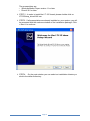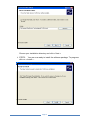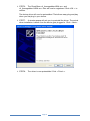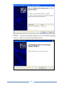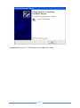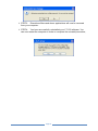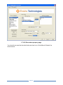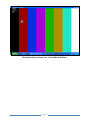
1
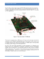
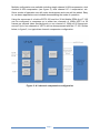
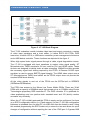
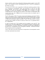
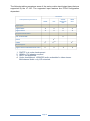
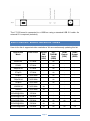
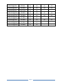
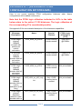
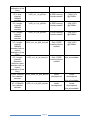
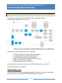
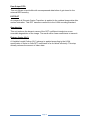
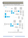
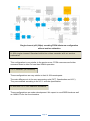
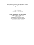
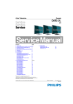
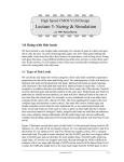
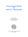
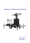
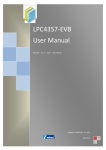
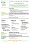
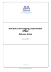
Model: LT-125 USER MANUAL A Lattice ECP3 based HD video compression and decompression evaluation platform. AUGUST 2012 Page 1 TABLE OF CONTENTS Table of Contents .................................................................................................................................... 2 Special handling instructions ................................................................................................................... 3 Introduction .............................................................................................................................................. 4 Notable Features ..................................................................................................................................... 6 HARDWARE Description......................................................................................................................... 7 Hardware Setup ....................................................................................................................................... 9 Supported Video Resolutions ................................................................................................................ 11 SOFTWARE Installation ........................................................................................................................ 13 Downloading the demo and driver application .................................................................................. 13 Installation Procedure ........................................................................................................................ 13 Software Uninstallation ...................................................................................................................... 21 Using the demo ..................................................................................................................................... 23 Appendix A – (Available FPGA Configuration Bitstreams) .................................................................... 26 Appendix B (FPGA Configuration Bitstreams description) .................................................................... 28 H.264 single channel 1080p30 encoder with quarter-pel motion estimation .................................... 28 H.264 dual-channel 1080p30 encoder with full-pel motion estimation .............................................. 32 H.264 single channel 1080p60 encoder with full-pel motion estimation ........................................... 33 H.264 single channel 1080p30 encoder with no motion estimation (Intra Only) ............................... 33 H.264 single channel Standard definition video encoder with no motion estimation ........................ 34 VC-1 encoder (all variants) ................................................................................................................ 34 H.264 and VC-1 four channel decoders ............................................................................................ 34 Further information ................................................................................................................................ 35 Copyright © 2012 Enciris Technologies, SAS. Other companies’ product names that may be used in this document are for identification purposes only and may be trademarks of their respective companies Page 2 SPECIAL HANDLING INSTRUCTIONS The circuit board contains CMOS circuitry that is sensitive to Electrostatic Discharge (ESD). Special care should be taken in handling, transporting, and installing LT-125 circuit board to prevent ESD damage to the board. In particular: Do not remove the circuit board from its protective anti-static bag until you are ready to use it. Handle the circuit board only at grounded, ESD protected stations. Avoid touching the boards circuitry, especially the DDR memories. Page 3 INTRODUCTION The LT-125 is a Lattice Semiconductor ECP3 FPGA based board for the evaluation of Enciris Technologies’ HD and SD video compression and decompression IP. The LT-125 is designed to demonstrate high performance h.264/AVC and VC-1 encoding in FPGA applications. Figure 1. Top view of the LT-125 Board. This board is equipped with an HDMI input, a DVI input with both single and dual link capabilities, and an SMPTE 3G/HD/SD-SDI input. These inputs can be used for one or multiple channel video capture and acquisition. An HDMI output is also provided for display in pass-through or decoding applications. As the LT-125 uses FPGA technology for video processing, it is inherently very flexible and can be configured for a multitude of operations. Enciris Technologies supplies tools to change the LT-125 operating modes by using a choice of different FPGA configurations. The supplied LT-125 configurations are full featured and have additional functionality that is not included in our standard h.264 and VC-1 IP deliverables. Please contact us for more information. Page 4 Multiple configuration are available including single channel H.264 compression, dual channel H.264 compression (see figure 2), dual channel VC-1 compression, etc. Some modes of operation are still under development and more will be added. Easy to use demo applications are included demonstrating the mode of operation. Using the resources of a Lattice ECP3-150 and four 32-bit Mobile DDRs the LT-125 can be configured to compress up to either two channels of 1080p HDTV at 30 frames per second video simultaneously or one channel of 1080p at 60 frames per second. Up to four channels of HDTV can be decompressed with the LT-125. Shown below, in figure 2, is a typical two channel compression configuration. Figure 2. A 2 channel compression configuration Page 5 NOTABLE FEATURES A platform for evaluating Enciris Technologies H.264 and VC-1 video compression and decompression IP. Uses a powerful Lattice ECP3 FPGA with 150 KLUTs for video processing Equipped with a DVI single and dual link video input Equipped with an SMPTE 3G/HD/SD/SDI video input Equipped with an HDMI video input Equipped with an HDMI video output Connects to a host PC via a USB2.0 cable type B Can be completely reconfigured for different modes of operation in seconds. FPGA Configuration bitstreams are uploaded directly via USB. JTAG is not required. Very simple setup Includes a PC based application for quick evaluation and configuration Includes Windows XP/Vista/7 32/64 bit support A simple SDK that includes DirectShow is available for developing custom applications around the LT-125. Page 6 HARDWARE DESCRIPTION Figure 3. LT-125 Block Diagram. The LT-125 evaluation module includes video input and output connectors, a series of video input equalizers and a level shifter, a Lattice ECP3-150 FPGA, DDR memories, a Lattice XP2-8, a USB device controller, power management electronics and a USB device controller. These functions are depicted in the figure 3. When high speed video signal passes through a cable, signal degradation occurs. The LT-125 is equipped with input equalizers to restore video signal quality. ST Microelectronics TMDS equalizers ICs are used for DVI and HDMI inputs. These devices are designed to handle video at rates exceeding 1080p60 and also provide the necessary signal level shifting required by the FPGA. A Gennum 3G-SDI input equalizer is used to assure SMPTE signal integrity. The HDMI video output uses a ST Microelectronics TMDS level shifter as the FPGA output does not provide the required HDMI levels directly. All the video signals in and out of the FPGA use the ECP3s built in SERDES (SERializer/DESerializer). The FPGA has access to four Micron Low Power Mobile DDRs. These are 32-bit DDRs with a capacity of 256Mbits each that operate at up to 133MHz using Enciris Technologies proprietary DDR controller IP. The DDR controller IP is optimized for video applications and can perform both standard burst and 2-D (block) random accesses very efficiently. When the LT-125 is initially powered the FPGA is empty and un-configured. As there is no ECP3 configuration device (i.e. Flash memory) on the LT-125, the configuration bitstream is uploaded from the host PC via USB each time the board is used. Using this method programming the ECP3 takes only a second or two and allows for quick changes of configuration without requiring the use of the JTAG port. A Cypress USB Page 7 device controller receives the configuration bitstream and then sends it to the XP2 which in turn serializes, via SPI, and programs the ECP3. The XP2 is configured at the factory via JTAG. The Lattice XP2 FPGA is also responsible for efficiently transferring packets of data (e.g. compressed, uncompressed video, and parameters) to and from the USB device controller. The LT-125 to host USB transfer rate is limited by the USB bandwidth. In theory the bandwidth is 400 MBits/s but in practice it is often considerably lower. This rarely has any impact on the transfer of compressed video (usually below the 10s of MBits/s) but can severely reduce the transfer rate of uncompressed video. The LT-125 requires 5 VDC. The power requirements depend on how the LT-125 is used. A dual channel system compressing both channels at 1080p30 while acquiring 1080p60 video (frame rate decimation being used) requires about 10 Watts. A 5 VDC 15 Watt wall mount power supply is provided. The LT-125 has a number of efficient switching power supplies on board to meet the FPGA core, IO, peripheral device, etc., requirements. In order to operate the LT-125 software must be installed on the host PC. This includes drivers, and demo applications. The installation procedure is described later in this document. For each LT-125 mode of operation a specific demo application is provided with a corresponding FPGA configuration bitstream. Windows XP/Vista/7 32/64 operating systems are supported. The LT-125 uses no host CPU resources for compression or decompression and as such host requirements are minimal. Page 8 HARDWARE SETUP The simplest usage configuration of the LT-125 evaluation board is shown in the following picture. Figure 4. In this configuration, a camera connects to one of the 3 LT-125 video inputs (up to two cameras can be connected at the same time when dual channel configuration is chosen). The LT125 is also connected to a 5V power supply and to a host computer via USB device cable. To accommodate for the numerous video sources, various low cost, off the passive cable adapters (e.g. HDMI to DVI) might be required. However, the signaling remains compliant with the inputs. The HDMI output normalizes resolution and loops video from any of the inputs through. The physical input/output connectors are shown below. Page 9 shelf, video video video The following table summarizes some of the various video input/output types that are supported by the LT-125. The supported input features are FPGA configuration dependent. Connector HDMI DVI SMPTE 3G/HD/SD1 SDI HDMI OUT Digital SDTV ● ● ● ● Digital HDTV ● ● ● ● Audio/Video Input Features Signal types Physical Connections ● SDI 75 ohm BNC ●1 DVI-D HDMI ●3 ● 2,3 ●4 ●4 ●3 Audio Signals Digital Audio embedded with video 1. 2. 3. 4. ●4 SMPTE in is under development HDMI to DVI adapter required HDCP not supported. Under development. HDMI/SDI audio embedded in video stream. Multichannel audio: only L/R extracted. Page 10 ●4 The LT-125 board is connected to a USB bus using a standard USB 2.0 cable. An external 5V is required (included). SUPPORTED VIDEO RESOLUTIONS Here is the list of supported video resolutions. We are continuously updating this list. Input Video Mode Pixel Clock DVID/H DMI Input (YUV) DVID/HDMI Input (RGB) HDMI Output (YUV) HDMI Output (RGB) 480i59.94 27 MHz - ok - - 576i50 27 MHz - ok - - 480p59.94 27 MHz - ok - - 576p50 27 MHz - ok - - 720p25 74,25 MHz - ok - - 720p59.94 74,25 MHz - ok - - 720p60 74,25 MHz - ok - - 1080i59.94 74,25 MHz ok - - - 1080i60 74,25 MHz ok - - - 640x480@60Hz 25 MHz - - - - 800x600@60 Hz 40 MHz - - - - 800x600@75Hz 50 MHz ok ok ok ok 800x600@85Hz 56 MHz ok ok - - 1024x768@60Hz 65 MHz ok ok ok ok Page 11 1280x768@60Hz 80 MHz ok ok ok ok 1280x960@60Hz 108 MHz ok ok ok ok 1280x960@85Hz 148,5 MHz ok ok - - 1280x1024@60Hz 108 MHz ok ok ok ok 1280x1024@75Hz 135 MHz ok ok ok ok 1280x1024@85Hz 157 MHz ok ok - - 1440x900@60Hz 106 MHz ok ok ok ok 1600x1200@60Hz 162 MHz ok ok - - 1920x1200@60Hz 154 MHz ok ok - - Page 12 SOFTWARE INSTALLATION In order to demonstrate the capabilities of the LT-125 and the Enciris Technologies IP some driver software needs to be installed on a PC running Windows XP/Vista/7 32/64bit operating system. For Windows XP users you must make sure the following prerequisite software is installed, if not already, on your system: Windows Media Player version 11 or later (For VC-1 encoder configuration) Download link: http://www.microsoft.com/windows/windowsmedia/player/download/download.asp x DirectX 9.0 or later Download link: http://www.microsoft.com/downloads/details.aspx?FamilyId=2DA43D38-DB714C1B-BC6A-9B6652CD92A3&displaylang=en All Windows users must have an H.264 decoder on their system. The link below downloads just but one of many available. Any H.264 DirectShow Decoder Filter (For H.264 encoder configuration) Example Download link: http://hax264.sourceforge.net Downloading the demo and driver application See appendix A for a list of available LT-125 configurations. Download the appropriate executable and follow the procedure below. The download link is as follows: http://www.enciris.com/lk/dataf/lt125_h264_driver_v2.14.msi Installation Procedure Please, follow these steps in order to run the software installation for your LT-125 device: STEP 1 : Make sure all prerequisites are installed before starting product installation. Page 13 The prerequisites are: o Windows Media Player version 11 or later o DirectX 9.0 or later STEP 2 : In order to install the LT-125 board, please double-click on LT125Setup_driverXXX.exe. STEP3 : If all prerequisites are already installed on your system, you will be prompted with the welcome window of the installation package. Click « Next » to continue. STEP4 : On the next window you can select an installation directory or stick to the default directory. Page 14 Choose your installation directory and click « Next » STEP5 : You are now ready to install the software package. To progress click on « Install » . Page 15 STEP6 : The DirectShow «lt_framegrabberH264.ax» and «lt_framegrabber1H264.ax« filter will now be registered. Click «OK » to confirm. The device driver will now be preinstalled. That allows easy plug and play when you first plug in your device. STEP7 : A window popup will ask you to preinstall the driver. The actual driver installation is done once the device gets plugged in. Click « Next ». STEP8: The driver is now preinstalled. Click « Finish ». Page 16 STEP9: You have successfully installed your LT-125 software package. Click on « Finish » to continue and reboot your PC. Page 17 STEP10: You can now connect your LT-125 device though USB. STEP11: You will now be prompted with the plug and play wizard of windows asking for device driver installation. On the button box asking to connect to windows update click on « No not this time » and click on « Next » Page 18 STEP12 : Select automatic installation and click « Next » STEP13 : You have successfully installed your device. Click « Finish » to terminate the installation and restart your computer. Page 19 Congratulations. Your LT-125 device is now ready to be used. Page 20 Software Uninstallation To remove the LT-125 software from your computer, please follow these steps: STEP1: execute the application called “Uninstall LT-125 Driver” in the installation directory. You can alternatively chose the uninstall executable from start menu. STEP2: On the next window click “Yes” to confirm that you want to uninstall the software package. Page 21 STEP3: Directshow filters and demo applications will now be removed from your computer. STEP4: You have successfully uninstalled your LT-125 software. You can now restart the computer in order to complete the uninstall procedure; Page 22 USING THE DEMO You may want to run the “LT-125 H.264 SC P30” demo application that is on your taskbar or start menu (as shown below) in order to test the device with the single channel 1080p30 FPGA configuration. Start menu and taskbar entry The application will launch a so called “directshow graph” with a video “Source Filter”, a video “Decoder Filter” and a video “Renderer Filter” as shown below. Note that video decoding usually involves lots of CPU resources. Make sure you configured your video decoder properly Directshow Graph showing H.264 decoding chain If you did not plug any video source yet, you can still test the board by checking color bar test mode on the prompted “DirectShow property page” (See picture below). Page 23 LT-125 Directshow property page You should now see the decoded video preview in an “ActiveMovie Window” as shown below. Page 24 Decoded video preview in an “ActiveMovie Window” Page 25 APPENDIX A – (AVAILABLE FPGA CONFIGURATION BITSTREAMS) Here is our current available FPGA configuration bitstream table. Newer configurations will be added continuously. Note that the FPGA logic utilization indicated in LUTs in the table below refers to the entire LT-125 bitstream. The logic utilization of the corresponding IP is considerably smaller. See appendix B for more detailed description of the bitstreams capabilities. Bitstream Description Name Special Features FPGA Logic utilization in [LUT] H.264 single channel 1080p30 encoder with quarter-pel motion estimation lt125_h264_sc_p30.bit 2 DDR memory blocks needed ~56K LUTs @133MHz H.264 dualchannel 1080p30 encoder with fullpel motion estimation lt125_h264_dc_p30.bit 4 DDR memory blocks needed ~110K LUTs @133MHz H.264 single channel 1080p60 encoder with fullpel motion estimation lt125_h264_sc_p60.bit 4 DDR memory blocks needed Not yet available H.264 single channel 1080p30 encoder with no motion estimation (Intra Only) lt125_h264_sc_p30_ionly Only 1 DDR memory blocks needed Not yet available H.264 single channel Standard definition video encoder with no lt125_h264_sc_sd_ionly Only 1 DDR memory blocks needed Not yet available .bit .bit Page 26 motion estimation (Intra Only) VC-1 dualchannel 1080p30 encoder lt125_vc1_dc_p30.bit 4 DDR memory blocks needed ~110K LUTs @133MHz VC-1 singlechannel 1080p60 encoder lt125_vc1_sc_p60.bit 4 DDR memory blocks needed ~90K LUTs @133MHz VC-1 singlechannel 1080p30 encoder lt125_vc1_sc_p30.bit 2 DDR memory blocks needed ~56K LUTs @133MHz VC-1 singlechannel 1080p30 encoder with no motion estimation (Intra Only) lt125_vc1_sc_p30_ionly.bit Only 1 DDR memory blocks needed ~56K LUTs @133MHz VC-1 singlechannel Standard definition video encoder with no motion estimation (Intra Only) lt125_vc1_sc_sd_ionly.bit Only 1 DDR memory blocks needed Not yet available H.264 1080p30 four channel decoder lt125_h264_4c_p30_dec.bit Under development Under development VC-1 1080p30 four channel decoder lt125_vc1_4c_p30_dec.bit Not yet available Under development Under development Not yet available Page 27 APPENDIX B (FPGA CONFIGURATION BITSTREAMS DESCRIPTION) H.264 single channel 1080p30 encoder with quarter -pel motion estimation This bitstream implements the h.264 video coding standard using the baseline/main/high profile up to level 4.1. Single channel p30 (30fps) encoding FPGA bitstream configuration This bitstream has following features implemented: 133MHz required for 1080p at 30fps compression low compression latency (less than a picture) All resolutions and frame rates supported Large +/-255x255 motion estimation search range Bitrates from 64Kbit/s to 80Mbit/s h.264 baseline profile up to level 4.1 Note that blocks in blue are included in the FPGA bitstream but not in the IP. The building blocks are as follows: DDR Controller 1 and 2 These multiport DDR memory controllers simplify the task of handling multiple data streams in and out of a mobile DDR SDRAM using 2-D transfers. Page 28 DDR Controller 1 handles current picture data whereas DDR Controller 2 takes care of past (already encoded) pictures. NOTE: This module also exists as a standalone IP Motion Estimation/Compensation This is the Motion Estimation (ME) and compensation engine for H.264 video encoder. This block consumes 540 clocks cycles per macroblock. Quarter-pel subpixel block matching is used in order to get the best possible match. The ME covers a search range of 256 horizontal and 256 vertical pixels. NOTE: This module also exists as a standalone IP Crossbar Switch This unit selects one video source and passes it downstream for compression and preview and another video source for the HDMI bypass. Video Front End This unit does a-priori processing on the input video such as Cropping, RGB to YUV4:2:2 colour space conversion and framerate decimation. Video Sync Gen This block does adjustment for certain video modes that are not compatible to HDMI standard. Acquisition Unit This unit stores the YUV4:2:2 video into memory via DDR Controller 1. It also dispatches the video for preprocessing. Color Adjustment Unit The video now enters a preprocessing phase prior to actual compression. The Color Adjustment Unit applies user defined HSBC (Hue, Saturation, Brightness and Contrast) adjustment to the video data. Deinterlacing Unit This is a content/motion adaptive deinterlacing filter for interlaced video content. Downscaling Unit This unit scales down video to any multiple of 16 pixels. The aspect ratio does not need to be preserved during downscaling. Separate downscaling can be performed for the compressed and uncompressed stream. Page 29 Spatial Noise Filter This unit applies non-linear edge preserving noise filtering in the spatial domain in order to remove high frequency salt-and-pepper noise. 4:2:2 to 4:2:0 Color Subsampling This unit does the chroma subsampling. The result of the subsampling is smaller resolution for chroma than for luma, taking advantage of the human visual system's lower acuity for color differences than for luminance. On Screen Display This module implements user defined “on screen text overlay". User can set up to 4 words of 16 characters each. Each word can be placed at user defined position on the frame. It is important to note that the overlay is performed prior to compression and is thus encoded into the encoded stream. If the input video width is greater than 720, large characters (16x32) will be used for OSD, otherwise 8x16 characters are used. User defined characters can also be used instead of the default ASCII character set. NOTE: The preprocessing unit (colour adjustment, deintrelacing, spatial noise filter and color subsampling) also exists as a standalone IP (Enciris Preprocessing IP) Temporal Noise Filter This module applies adaptive filtering to compensate for noise that is detected using motion statistic. Bitrate Controller (BRC) This unit ensures that the user given target bitrate is met according to the chosen BRC policy (CBR, VBR etc…). The quantization level is dynamically adjusted between a minimum and maximum level in order to reduce the dynamic range of the compressed coefficients. This will for example reduce the bitrate while increasing the amount of coding artifacts and vice versa. Parameter and Status Registers This is a configuration unit which ensures that the right programing is applied to the configuration registers. It also reads status registers back to the user via USB bus interface unit. Enc Output FIFO This unit fills an output buffer with compressed data before it get stores to the external DDR memory. Page 30 Raw Output FIFO This unit fills an output buffer with uncompressed data before it get stored to the external DDR memory. DCT/IDCT An integer 4x4 Discrete Cosine Transform is applied to the residual image data after motion estimation. This DCT transform conforms to the H.264 encoding standard. Quantization This unit reduces the dynamic range of the DCT coefficient introducing a nonreversible degradation of the image. The result will be fewer coefficients to transmit. Entropy Coder (VLC) A Variable Length Coding (VLC) scheme is applied according to the H.264 specification in order to code DCT coefficients of a 4x4 block efficiently. This step actually reduces the amount of video data. Page 31 H.264 dual-channel 1080p30 encoder with full-pel motion estimation This core IP implements the h.264 video coding standard using the baseline/main/high profile up to level 4.1. It is basically a duplication of previous IP block except that Full pel motion estimation is applied instead of quarter pel motion search. Dual channel encoding FPGA bitstream configuration Page 32 Bus Interface Muxer 1 and 2 This unit premultiplexes compressed and uncompressed video for each of the two channels prior to actual transmission via USB bus interface. H.264 single channel 1080p60 encoder with full -pel motion estimation From the data flow point of view, this bitstream does not vary much from its 30fps counterpart. Only some FPGA resources are duplicated as shown in the picture bellow. Single channel p60 (60fps) encoding FPGA bitstream configuration H.264 single channel 1080p30 encoder with no motion estimation (Intra Only) This configuration is very similar to the single channel variant except that motion estimation logic as well as one DDR block is removed. Page 33 Single channel p30 (30fps) encoding FPGA bitstream configuration without motion estimation H.264 single channel Standard definition video e ncoder with no motion estimation This configuration is very similar to the previous one. FPGA resources are further narrowed down to allow for less than 66MHz operation. VC-1 encoder (all variants) These configurations are very similar to their H.264 counterparts. The main difference is in the core processing units (DCT, Quantization and VLC). They are modified according to the VC-1 encoder specification. H.264 and VC-1 four channel decoders These configurations are under development. We expect to use 4DDR blocks as well as 140KLUTs for the four decoders. Page 34 FURTHER INFORMATION To contact us for further information on this or any other Enciris Product: Enciris Technologies 42, Avenue de l’Europe 81600 Gaillac France Tel: +33 (0)5 81 18 01 12 Email: [email protected] Web: http://www.enciris.com Page 35