1
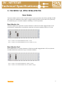
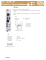
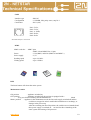
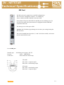
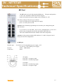
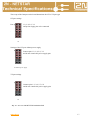
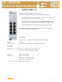
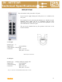
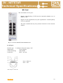
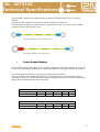
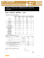
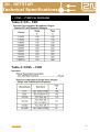
2N - NETSTAR
Technical Specifications
Technical Specifications
2N - NETSTAR
Dear customers,
We thank you for your decision to buy the new 2N® - NETSTAR
communication system made by the Czech producer 2N
Telekomunikace a.s. Prior to starting to use the system, please read
carefully the instructions stated in this User’s Manual. If you use
the system in compliance with the instructions contained herein, it
will not only ensure a proper communication, but it will also help to
save your time and money.
The User’s Manual serves for all types of the 2N® - NETSTAR
Communication System. The basic operation is equal with all
system models, any potential differences are described separately.
Should you have any questions, please address these to your sales
agent, service organisation, or if necessary directly to the producer.
www.2n.cz
2
CONTENT
1.
SYSTEM INSTALLATION ................................ Chyba! Záložka není definována.
1.1. Selection of the Installation Site ........................................................................... 4
1.2. Unwrapping and Control ....................................................................................... 5
1.3. Installation ............................................................................................................. 5
1.3.1. System Installation ............................................................................................. 5
1.3.2. System Connection ............................................................................................ 5
2.
TECHNICAL SPECIFICATIONS ...................... Chyba! Záložka není definována.
2.1. Basic Module ......................................................................................................... 6
2.1.1. Basic Module Lite............................................................................................... 6
2.1.2. Basic Module Profi ............................................................................................. 6
2.2. Extension Module .................................................................................................. 7
2.3. Position and Port Numbering ............................................................................... 8
2.4. CPU Card................................................................................................................ 9
2.5. CPU Card – Extension Module ........................................................................... 11
2.6. SWITCH Card ....................................................................................................... 11
2.7. PRI Card ............................................................................................................... 14
2.8. BRI Card ............................................................................................................... 16
2.9. DVL Card .............................................................................................................. 18
2.10. DIGITAL COMBO Card ........................................................................................ 19
2.11. 4ASL/4AVL Card .................................................................................................. 21
2.12. AVL Card .............................................................................................................. 22
2.13. GSM Card ............................................................. Chyba! Záložka není definována.
2.14. Audio / IO / Relay Card ........................................................................................ 24
2.15. IP Card.................................................................. Chyba! Záložka není definována.
3.
POWER SOURCE ............................................................................................ 28
3.1.
3.2.
3.3.
4.
Power Supply Connection .................................................................................. 28
System Grounding .............................................................................................. 28
Power Supply Backup ......................................................................................... 29
TECHNICAL SPECIFICATIONS II ................................................................... 30
www.2n.cz
3
1. SYSTEM INSTALLATION
Selection of the Installation Site
.
The following aspects shall be taken into consideration while selecting a site for the system
installation:
• Good accessibility:
All interfaces for the connection of the telecommunication interfaces or data network connections, as
well as the switch-on, switch-off and system reset controls are placed on the front side.
• Protection against humidity and extreme temperatures:
The appliance may never be placed close to heat sources (radiators) or places
exposed to direct sunshine. Also places with high humidity (such as
bathrooms and cellars), places with significant temperature fluctuation (next to
doors, windows, air-conditioning), dusty places (workshops, etc.) or places
exposed to aggressive gases (accumulator room, boiler room) as well as
places with intensive vibrations and places exposed to shocks (compressor
rooms, heavy industrial operations) should be avoided. The system should be
installed horizontally.
•
Installation of infrastructure in the building:
The system was designed for installation in a 19“ rack and connection to the structured wiring
infrastructure with termination at a CAT 3 or CAT 5 patch panel. If the infrastructure is already
ready the switchboard installation site is usually given and can not be further changes. The
interface must however be adjusted for the connection via RJ 45 8/8 plugs.
•
GSM signal quality:
If a GSM card is a part of your system (or will become later on), it is necessary to consider that the
cable leading from the GSM card to the GSM antenna is usually 3m long (max. 10m). You should
ensure that within this diameter from the selected system installation site a place with good GSM
signal suitable for placement of the GSM antenna is available. *)
•
Theft protection:
While selecting the installation site the insurance company conditions
well.
should be regarded as
Note: In the areas with very poor GSM signal level or high number of GSM gates the use of internal
(takes the position of a line card) or external GSM splitter is advantageous.
www.2n.cz
4
Unwrapping and Control
If you have not already done so, please check the completeness of the delivery.
The wrapping of the basic or extension module is usually used also for the
transportation of other, separately acquired system components (antennas and other
small additional equipment). These can be checked by matching the items on the
supply list and the ordering numbers stated on all components. Usually, the system is
delivered as tailor made according to the submitted order. The installation set,
electronic documentation on a CD and warranty certificate are a part of the delivery.
The remaining components such as telephone units and other terminals or additional
appliances are delivered separately.
Installation
System Installation
The system is installed into a RACK min. 400 mm deep. The height of each module is 3U – 132 mm.
The system was not designed to be equipped with an active cooling unit, however the producer
recommends in order to achieve a better air ventilation in case of bigger installations (more modules
above each other) to leave a gap of e.g. 1U between the separate modules. For this purpose an
organizer, which at the same time will ensure a better manipulation with the wiring, can be used.
For a shelf installation the system is equipped with 4 stands that create a gap between the shelf and the
module body to ensure sufficient system ventilation.
System Connection
The connection of the system to the telecommunication network is subject to local national regulations
and directives. The interface of the line cards terminates in a RJ45 plug.
Only appliances complying with the basic requirements and further specifications of the directive no.
1999/5/ES (Government Directive No. 426/200 Coll., which stipulates the technical requirements of
radio and telecommunication terminal appliances, in the wording of the later regulations) may be
connected to the internal analogue interface.
The same applies for the connection to the 230 V or 115 V power supply Network, which is subject to
the local and national regulations and directives.
The supplied wiring including an additional connection to the single ground point is used for
connection. If you do not use the additional system grounding, the over voltage protection integrated
in the line cards will not work.
The 2N® - Netstar communication system was designed as digital appliance (TDM circle switching)
with sufficiently powerful processor and LAN connection with integrated VoIP telephony.
www.2n.cz
5
2. TECHNICAL SPECIFIKATIONS
Basic Module
The basic module consists of CPU, Switch Card and 3 system positions with AD bus and IRQ for PRI
and VoIP cards. Furthermore, the module is equipped with 9 positions for line cards. The system may
be extended by up to 4 extension modules containing 11 line card positions.
Basic Module Lite
The Basic Module Lite represents a business alternative of the basic module equipped with an CPU
card, Switch X card that does not enable the connection of extension modules and one AVL card.
Obj. no. 101014 2N NETSTAR BASIC module 8x ASL
Obj. no. 101034 2N NETSTAR BASIC rack basic module 8x AVL
Basic Module Profi
Basic Module Profi is a business alternative of the basic module equipped with a CPU card, Switch
card that enables the connection of up to 4 extension modules.
Obj. no. 101011 2N NETSTAR PRO basic module (empty)
Obj. no. 101031 2N NETSTAR PRO rack basic module (empty)
www.2n.cz
6
Extension Module
The extension module is equipped with an 8-bit CPU, which controls up to 11 analogue line cards.
The following cards are supported: AVL, ASL, GSM and AUDIORELE.
Obj. no. 101016 2N NETSTAR PRO extender analogue only
Obj. no. 101036 2N NETSTAR PRO rack extender analogue only
www.2n.cz
7
Position and Port Numbering
Each card and port is assigned a specific unique HW address.
The address consists of 4 parts and is stated in the form: R:C:B:P, whereas the separate letters stand
for the following:
R – rack
Rack represents the entire system appliance consisting of the basic module and four extension modules
(case), in the current version only one Rack is supported. The rack address is thus 0.
C – case
Covers the basic or one of the four extension modules.
The address of the basic module is 0, the extension modules are assigned addresses from 1 to 4
according to their SWITCH card Connections.
B – board
The separate cards (board) are assigned addresses from left to the right, both in the basic as well as the
extension modules. The address of the first position in the module is 0.
Compared to the extension module, in which the cards are assigned addresses from 0 to 11, the
assigning of addresses in the basic module is governed by predefined rules.
The basic module uses following rules for the card positions and assigning of addresses.
Address 0
Reserved for controlling CPU only (position 1)
– the card address is 0:0:0
Addresses 1,2,3
Reserved for the PRI and VoIP cards (positions 2,3 and 4)
– the cards addresses are 0:0:1, 0:0:2 and 0:0:3
Address 4
Reserved for the SWITCH card (position 5)
– the card address is 0:0:4
Addresses 5, 6,7,9,10,11,13,14,15
The addresses 8 and 12 are skipped. The addresses correspond to the positions 5,6,7,8,9,10,11,12,13
and can be used for any line card. An exception are the positions with the addresses 5, 9 and 13, in
which if you use a BRI or DIGITAL COMBO card the first 2 ports on the card are always NT and
may not be changed.
P – port
The card ports are assigned the addresses from left to the right and from top to the bottom.
The addresses start with 0.
For the purpose of better orientation the PRI, GSM and Audio/IO/Relay cards have the serial numbers
of the ports printed on their front side.
www.2n.cz
8
CPU Card
The card is an inseparable part of the basic module.
- It contains all necessary interfaces needed for the communication with the
system.
-
It is only installed in the basic module, always in the position with the 0 HW
address.
LAN
Interface type
Connection
– Eth T-Base 10/100
– RJ45
Pin1= transit +,
Pin2= transit -,
Pin3= receive +,
Pin6= receive -
LAN interface connection
USB
Interface type
Connection
Physical layer
Power supply
Consumption
– USB 1.1
– 2x USB-A
– Low Speed - 1.5Mbits/s
– 5V
– max. 100mA
USB Host interface Connection
www.2n.cz
9
COM
Interface type
Configuration
Connection
– RS232C
– 115200Bd, 8bit, parity: none, stop bit: 1
– RJ11 (6x6)
Pin1= TxD-,
Pin2= TxD+,
Pin3, 4= GND,
Pin5= RxD+,
Pin6= RxD-
RS 232C interface connection
MMC
MMC cards slot – MMC 7pins
– MMC 4.0 and MMC Plus 13 pins
Buses
– 1-bit (MMC) and 4-bit (MMC4.0 and MMC+)
Power supply
– 3,3V
Reading speed
– up to 22, Mb/s
Writing speed
– up to 18 Mb/s
RES
The Reset button will reboot the entire system.
Maintenance switch
ON position
– appliance switched on
OFF position
– appliance switched off, the position is equipped with a
3s by-pass for the switching into the Maintenance
Mode
Maint. position – appliance in the maintenance mode, the line cards supply switched off and the
card drivers stopped in order to enable their maintenance or exchange, or
changes in the port set-up.
After the switching into the ON position, the card drivers are launched and
their power supply is switched on - no need for the re-launching of the
entire system and starting of all processes.
www.2n.cz
10
CPU Card – Extension Module
.
The card is an inseparable part of the extension module.
-
Contains the proprietary interface for the communication with the
SWITCH card.
-
It is only installed in the extension module, always into the positions
with the 0 HW address.
The SWITCH board connection interface
Interface type
Connection
– proprietary
– RJ45 (8/8)
Maximum connection length 160cm (wiring supplied as a part of the
extender package)
Total interface capacity 88 calls
SWITCH Card
The SWITCH card is an inseparable part of the basic module.
-
It can be supplied in two HW alternatives.
Switch X without the possibility of extension modules connection, standardly supplied
as a part of the Basic Module Lite version.
Switch with the possibility of the connection of up to
4 extension modules.
-
Both card versions are always equipped with 1 PRI interface
and basic connection field that is in charge of the connection
the entire system.
-
www.2n.cz
of call in
It is only used in the basic module and is always installed in the position with 4 as
the HW address.
11
Extender connection interface
Interface type
Connection
– proprietary
– RJ45 (8x8)
Maximum connection length 160cm (wiring supplied as a part of the extender package)
Total interface capacity 124 calls
Ratio capacity of the interface 4x 31 calls
Maximum capacity per 1 extender 88 calls
1x PRI interface
Interface type
Protocol
Connection
– S0 without power supply / NT-TE
– DSS1 – EURO ISDN
– RJ45 with LED control
Pin1, Pin2 = broadcasting couple
Pin4, Pin5 = reception couple
PRI interface connection
The set-up of the Jumpers on the board determines the NT or TE port type
For NT port the pins 1-3, 2-4, 5-7, 6-8 should be
connected
For TE port the pins 1-2, 3-4, 5-6, 7-8 should be
connected.
NT port set-up
TE port set-up
LED control lamp
RED
NO LIGHT
GREEN
www.2n.cz
- port not allowed by the licence
- port allowed by the licence, the line is not connected
- communication interface connected to the 2nd layer
12
Connection field
Type
– ZARLING
Total capacity 512 channels
Maximum number of simultaneous calls up to 172 – according to configuration
Case 1
4
Case 2
Main
Switch
(Zarlink)
Case 31
Case 4
Falc E1
(board 4
SWITCH)
Iom2 0
Iom2 1
Vip11
Iom2 0
Iom2 1
Vip15
Delic0
switch
(board 4
SWITCH)
Delic1
switch
(board 4
SWITCH)
0123
Zarlink
switch
(board 1
QUADE1)
Iom2000
Vip13
Vip14
10 11 12 13
Iom2000
Vip9
Vip10
Omap
Mcbsp
Iom2000
Vip5
Vip7
9
14
0123
Vip6
Omap
DSP
8
Iom2 0
Iom2 1
Delic2
switch
(board 4
SWITCH)
PCM
0,1,2,3
Falc E1 0
Falc E1 1
Falc E1 2
Falc E1 3
board
0,1,2,3
Scheme of the connection field on the SWITCH card.
Installation of the separate cards in the ports 1 to 3 of the Switch card bus if no ZARLIG is used with
the PRI card.
CPU
- 0,1,2,3
Position 1
- 0 on PRI = 1, 1 on PRI = 2, 2 on PRI = 0, 3 on PRI = 3
Position 2
- 0 on PRI = 2, 1 on PRI = 0, 2 on PRI = 1, 3 on PRI = 3
Position 3
- 0 on PRI = 0, 1 on PRI = 1, 2 on PRI = 2, 3 on PRI = 3
Switch - 0,1,2,3
The card ports are marked blue, the Switch buses are marked red.
The CPU card and the SWITCH card are filled 1:1.
If more than 3 ports are occupied on the card or cards in the positions 1, 2 and 3, the PRI cards must
be equipped with another ZARLING connection field. This ensures that the call channels of all ports
are connected to the basic connection field of the SWITCH card.
www.2n.cz
13
PRI Card
The PRI card can be supplied in several HW configurations.
The card can be configured to contain 1, 2 or 4 PRI ports,
with or without included ZARLING connection field.
If more than 3 PRI ports (the SWITCH card PRI port not including) are to be
served by the system, the system needs to be equipped with the ZARLINK
connection field cards.
The factory pre-set of the ports is TE.
Attention: the NS Admin programming tool uses these port settings during the
HW activation.
The card is installed into the position 1, 2 and 3 of the basic module, in between
the CPU and SWITCH cards.
1 to 4 x PRI port
Interface type
Protocol
Connection
– S0 without power supply / NT-TE
– DSS1 – EURO ISDN
– RJ45 with LED control lamp
TE modus
Pin1, Pin2 = reception couple
Pin4, Pin5 = broadcasting couple
NT modus
Pin1, Pin2 = broadcasting couple
Pin4, Pin5 = reception couple
www.2n.cz
14
PRI interface connection
The set-up of the Jumpers on the board determines the NT or TE port type
For NT port the pins 1-3, 2-4, 5-7, 6-8 should be
connected
For TE port the pins 1-2, 3-4, 5-6, 7-8 should be
connected
NT port set-up
TE port set-up
LED control lamp
RED
NO LIGHT
GREEN
www.2n.cz
- port not allowed by the licence
- port allowed by the licence, the line is not connected
- communication interface connected to the 2nd layer
15
BRI Card
-
The BRI card services 8 fully functional BRI ports. The port configuration
is TE or NT, with PPT or MPT line interface support.
On the NT interface the power supply can be switched off - 42V.
The factory settings of the ports are as follows:
- ports 0,2,4 and 6 preset as NT with power supply
- ports 1,3,5 and 7 preset as TE
Attention: the NS Admin programming tool uses these port settings during the
HW activation..
-
if you desire to use the BRI ports for the synchronisation, no line card
position may be skipped between this card and the SWITCH card.
The card is installed into the basic module on the line card position.
Attention: on the positions with the HW addresses 5, 9 and 13 the ports 0 and 1
always have the NT configuration.
8x BRI port
Interface type
Protocol
Connection
– S0 (NT-S/T, LT-T) with phantom power supply - 42V
– S0 (TE-S/T, LT-S) without power supply
– DSS1 – EURO ISDN
– RJ45
TE modus
Pin3, Pin6 = reception couple
Pin4, Pin5 = broadcasting couple
NT modus
Pin3, Pin6 = broadcasting couple
Pin4, Pin5 = reception couple
www.2n.cz
16
The set-up of the Jumpers on the board determines the NT or TE port type
NT port settings
Pins
1-2, 3-4, 5-6, 7-8
and power supply pins to be connected
¨
NT
Settings of the NT port without power supply
Connect pins 1-2, 3-4, 5-6, 7-8
and do not connect the power supply pins
NT without power supply
TE port settings
Connect pins 1-3, 2-4, 5-7, 6-8
and do not connect the power supply pins
TE
Obj. no. 1011118 2N NETSTAR module 8x BRI
www.2n.cz
17
DVL Card
The DVL card contains 8 ports used for the connection of the Star Point digital
telephone sets.
-
the board always contains two sources of power per
each four ports
0,1,2,3 a 4,5,6,7. If there occurs a short-circuit in the wiring (e.g. because
of connection of an analogue phone), the power supply will be
disconnected. After the technical deficiency was repaired, the power
supply source will start to feed power into the ports again.
-
The card is only installed into the position of the line card of the basic
module.
8x DVL port
Connection
Interface type – Upn (NT-U), LAP-S with power supply 48V
Protocol
– Cornet II
– RJ45
Pin4, Pin5 = broadcasting/ reception
DVL interface connection
Obj. no. 1011128 2N NETSTAR module 8x DVL
www.2n.cz
18
DIGITAL COMBO Card
The Digital Combo card consists of 4 BRI ports
and 4 DVL ports used for the connection of the digital telephone sets.
-
The specifications and characteristics of the ports match the
specifications and characteristics of the card itself.
-
If you desire to use the BRI port for synchronisation purposes, no line
card position may be skipped between this card and the SWITCH card.
-
The card is installed into the line card position of the basic module.
Attention: on the positions with the HW addresses 5, 9 and 13 the ports 0
and 1 always have the NT configuration.
4x DVL port
Protocol
RJ45 Connection
Interface type – Upn (NT-U), LAP-S with 48V power supply
– Cornet II
– two conductors, Pin4 and Pin5 = broadcasting/ reception
4x BRI port
Interface type
Protocol
Connection
– S0 (NT-S/T, LT-T ) with phantom power supply -42V
– S0 (TE-S/T, LT-S ) without power supply
– DSS1 - EURO ISDN
– RJ45 - four conductors
Pin3, Pin6 = broadcasting couple
Pin4, Pin5 = reception couple
Obj. no. 1011124 2N NETSTAR module 4x BRI/4x DVL
www.2n.cz
19
The set-up of the Jumpers on the board determines the NT or TE port type
NT port settings
Pins
1-2, 3-4, 5-6, 7-8
and power supply pins to be connected
¨
NT
Settings of the NT port without power supply
Connect pins 1-2, 3-4, 5-6, 7-8
and do not connect the power supply pins
NT without power supply
TE port settings
Connect pins 1-3, 2-4, 5-7, 6-8
and do not connect the power supply pins
TE
www.2n.cz
20
4ASL/4CO Card
The card contains 4 ASL ports and 4 AVL ports.
-
In case of power supply shortage the ASL ports are 1:1 switched to the
AVL ports.
-
We recommend to only connecting the telephone sets, which do not need
additional power supply and are in compliance with the basic
requirements and further respective provisions and stipulations of the
1999/5/ES Directive to the AVL ports.
-
The card can be installed into any line position of the basic or the
extension modules.
4 x CO port
Interface type – U
Signalisation
– reverse polarity, ¨
CLIP reception – FSK, DTMF
Connection
– RJ45 – two-wire
Pin4, Pin5 = a/b wires
ASL interface connection
4x ASL port
Interface type – analogue with power supply -60V
Signalisation
– reverse polarity,
CLIP broadcasting
– FSK, DTMF
Connection
– RJ45 - two-wire
Pin4, Pin5 = a/b wires
Obj. no. 1011224 2N NETSTAR module 4xCO / 4x ASL
www.2n.cz
21
ASL Card
The card contains 8 AVL ports.
-
Support of broadcasting of CLIP into the connected telephone sets via
DTMF or FSK.
-
Support of status signalisation, for pulse signalisation a constant polarity
reverse is generated.
-
The card is installed into any line position of the basic or the extension
modules.
Obj. no. 1011218 2N NETSTAR module 8x ASL
8x ASL port
Interface type – U analogue with power supply - 60V
Signalisation
– reverse polarity,
CLIP broadcasting
– FSK, DTMF
Connection
– RJ45 – two-wire
Pin4 = GND, 0V
Pin5 = -60V
ASL interface connection
www.2n.cz
22
GSM Card
The GSM card can be supplies in several HW configurations.
-
Configuration with 1, 2 or 4 GSM ports (channels)
-
The exchange of the SIM card in the GSM modules is only allowed if the
card power supply is switched off, i.e. if the system is switched to the
maintenance mode or completely switched off.
-
An antenna must be connected to the SMA antenna connection; otherwise
GSM module damage may occur.
-
1x SIM for 1 GSM module is supported
-
The card is installed into any line position of the basic or the extension
modules.
GSM module
Module type
– SIEMENS TC35i, SIEMENS MC39
SIM
Typ karty
www.2n.cz
– SIM small 3V
23
Audio / IO / Relay Card
The card can be supplied in two HW configurations.
-
The card configuration is 2x AUX and 4 x IO/Relay
Or 4 x AUX and 8 x IO/Relay
-
The card is installed into any line position of the basic or the extension
modules.
4 or 8x IO-relay port
Interface type – IO/relay
Port function
– according to chart
Connection
– removable WAGO connector, 8 pins
1port – consisting of a pin couple
2 or 4x AUX port
Connection
Interface type – analogue
– Jack plug 3,5 mm stereo
Pin0 (back ring) = GND,
Pin1 (middle ring) = Right channel
Pin2 (front ring) = Left channel
Input resistance: 160-380 kOhm (type 270kOhm)
Input voltage range: max +-2,223V AC
Output resistance: type 0.25Ohm
Output voltage range: max +-2,223V AC
www.2n.cz
24
Connection
Configuration
1
2
3
4
5
6
7
8
9
Configuration
Description
relay output
without power
supply from NS,
floating
Binary output
without power
supply from NS,
floating
relay output
without power
supply from NS,
floating (inverse
logics)
Binary input
without power
supply from NS
with shortcircuit
possibility,
floating
Binary input
without power
supply from NS
after connection,
floating
Binary input
without power
supply from NS
with shortcircuit
possibility,
grounded
Binary input
without power
supply from NS
to - with shortcircuit
possibility,
floating
Binary input
without power
supply from NS
after connection,
grounded
Binary input
with power
supply from NS
to - after
connection,
floating
www.2n.cz
Inner
NS
Source
NS
Direction
from/ to
OUT
NO
IN
OUT
NO
IN
OUT
NO
IN
OUT
NO
Settings Description
standby:
connected:
standby:
connected:
standby:
connected:
standby:
not conducting (disconnected + a -)
conducting (connected + a -)
not conducting (disconnected + a -)
conducting (connected + a -)
n/a
n/a
detects
connected:
standby:
detects
conducting (connected + a -)
connected:
standby:
not conducting (disconnected + a -)
conducting (connected + a -)
connected:
standby:
connected:
not conducting (disconnected + a -)
n/a
conducting (connected + a -)
standby:
detects
connected:
standby:
connected:
conducting (connected + a -)
conducting (connected + a -)
n/a
standby:
conducting (connected + a -)
connected:
standby:
connected:
detects
n/a
conducting (connected +, - a BGND)
standby:
detects (- grounded to BGND)
connected:
standby:
connected:
conducting (connected +, - a BGND)
n/a
conducting (connected + a -)
standby:
detects
connected:
standby:
connected:
conducting (connected + a -)
conducting (connected +, - a BGND)
n/a
standby:
conducting (connected +, - a BGND)
connected:
standby:
connected:
detects (- grounded to BGND)
conducting (connected + a -)
n/a
standby:
conducting (connected + a -)
connected:
detects
Jumpers
4+6
3+4
1+2
1+3, 4+6
IN
OUT
NO
IN
OUT
NO
1+3, 2+4
1+3, 4+6,
5+7
IN
OUT
ANO
1+2, 3+5,
7+8
IN
OUT
NO
IN
OUT
ANO
1+3, 2+4,
5+7
1+3, 2+4,
7+8
IN
25
Binary input
with power
supply from NS
to + after
connection,
floating
10
OUT
ANO
"=12"
NO
IN
Connection
Configuration
12
13
Configuration
Description
Binary input
with power
supply from NS
to + after
connection,
grounded;; relay
output with
power supply
from NS do +,
grounded
Inner
NS
Source
OUT
16
17
detects
connected:
standby:
connected:
Settings Description
standby:
conducting (connected +, - a BGND)
connected:
standby:
feeds (- grounded to BGND)
conducting (connected +, - a BGND)
Jumpers
IN
ANO
"=13"
NO
www.2n.cz
connected:
standby:
1+3, 2+4,
6+8
1+3, 2+4,
5+7, 6+8
OUT
connected:
standby:
connected:
standby:
detects (- grounded to BGND)
conducting (connected + a -)
feeds (+ grounded to BGND)
conducting (connected + a -)
1+3, 2+4,
5+6, 7+8
IN
IN
15
conducting (connected + a -)
ANO
Binary input
with power
supply from NS
to - after
connection,
grounded;; relay
output with
power supply
from NS to -,
grounded
relay output
with power
supply from NS
to - after
connection,
grounded
Binary input
with power
supply from NS
to -, floating,
after connection
grounded
N/a –
permanent
short-circuit
during
switching
standby:
NS
Direction
from/ to
OUT
14
conducting (connected + a -)
n/a
IN
OUT
11
standby:
connected:
OUT
ANO
connected:
standby:
connected:
standby:
connected:
standby:
detects (+ grounded to BGND)
connected:
standby:
feeds (+ grounded to BGND)
n/a
5+6, 7+8
connected:
standby:
connected:
standby:
n/a
n/a
feeds (+ grounded to BGND)
detects
3+4, 5+6,
7+8
connected:
standby:
connected:
standby:
detects (+ grounded to BGND)
1+2, 3+4,
5+6, 7+8
n/a
IN
OUT
ANO
IN
OUT
ANO
IN
1+2, 3+5,
4+6, 7+8
connected:
26
18
Binary input
with power
supply from NS
to -, floating
OUT
ANO
IN
standby:
feeds to -
connected:
conducting (connected + a -)
standby:
detects against BGND
connected:
conducting (connected + a -)
3+5, 4+6,
7+8
VoIP Card
The VoIP card can be supplies in several HW configurations.
4, 8, 16, 24 or 32 voice channels.
(IEEE 802.3) Ethernet 10/100 FullDuplex
The card is installed into the position 1, 2 and 3 of the basic module, in between the CPU and
SWITCH cards.
www.2n.cz
27
3. POWER SOURCE
ATTENTION!
These parts are connected with the power supply network and operate with a life
dangerous voltage. Any repairs and exchanges of the parts may only be
done by the producer!! Only the following maintenance works are
permitted:
• Safety fuse exchange
• Connecting and disconnecting of the power supply cable
POZOR!
Před manipulací
odpojte od sítě!
•
ATTENTION! Such maintenance works may only be executed while
the system is not connected to the power supply network!!!
Power Supply Connection
The detachable power supply cable is used for the connection to a regular power outlet. If necessary,
the cable may easily be disconnected from the switch-board. In case of the switch-board installation
outside the 19“ rack the power supply cable may be conducted to a power outlet either freely or
through a cable ledge.
•
System Grounding
Of course, the system is also grounded via the power supply network (thanks to the protective earth
conductor – if this is connected to the outlet). However, such grounding is not considered sufficient –
with regard to the danger resulting from the fact that the system may easily be disconnected from the
power supply network (over-voltage stemming from any line may thus easily be spread to the system
chassis and from there to any other line!).
ATTENTION! The system should thus optimally
be connected from the main switchboard through a
yellow-green conductor with a diameter of not less
than 4mm2 to the grounding ledge. In case of
emergency the “earth” should be connected by such
conductor (i.e. non-disconnectedly) to at least the
closest power supply outlet (make sure that the
outlet is connected correctly).
The conductor should be attached to the system
using the earthed connector
(on the backside of
the system panel, marked with the grounding
symbol) that is to be fixed properly. The grounding
should be connected prior to the connection of any
other wiring!!!
www.2n.cz
28
The grounding conductors are supplied with any package containing either basic or extension
modules.
The length of the conductor is for the basic and the extension unit 1500 mm
The ends of the conductor are equipped with a 4 mm diameter eyelet, one end of the basic module
conductor has an 8 mm diameter eyelet.
Grounding conductor of the extension unit
Grounding conductor of the basic unit
•
Power Supply Backup
For the backup of the power supply in case of power shortage an on-line UPS appliance is used. The
UPS is to be connected pursuant to the documentation supplied for the separate types and producers.
The following chart will help you to design an optimal UPS performance.
The values stated in the unconducting chart serve for information only, the consumption and the
performance of the 2N® - NETSTAR system change according to the current operational system load
and the HW configuration of the separate modules.
UPS - 800W / 1000VA
Number of cases
Backup time
1
150 min
2
70 min
3
50 min
4
-
5
-
4
70 min
5
50 min
UPS - 1600W / 2200VA
Number of cases
Backup time
www.2n.cz
1
240 min
2
150 min
3
100 min
29
4. TECHNICAL SPECIFICATIONS
Basic technical specifications
Nominal power supply network voltage
Power supply voltage tolerance
Nominal frequency
Input
Fuse
Recommended power backup source
External backup power source voltage
Max. backup source consumption
Typical operation time with fully charged batteries
Basic unit size
Basic unit weight
Extended unit size
230 V or 115V
+/- 10 %
50 Hz
160
10A
482x133x310 mm (84HPx3U)
12.5 kg
482x133x310 mm (84HPx3U)
Extended unit weight
12.5 kg
Communication interface
LAN
Pin1=transit +, Pin2=transit -,
Pin3= receive +, Pin6= receive -
Signals
Transmission speed
10/100 Mb/s
Interface type
Eth T-Base 10/100
USB
Signals
USB -A
Transmission speed
1,5 Mb/s
Interface type
2xUSB v1.1
RS 232
Pin1= TxD-, Pin2= TxD+, Pin3aPin4= GND,
Pin5= RxD+, Pin6= RxD-
Signals
Transmission speed
115200 Bd
Interface type
RS 232C / 115200Bd,8bit ,parity=noon, stop bit=1
MMC
Signals
MMC 7pins and MMC Plus 13 pins
Transmission speed
up/down 18/22 Mb/s
Interface type
1-bit (MMC) and 4-bit bus
Climate conditions
Temperature range
Relative air humidity
Premises description – basic characteristics
Operational position
www.2n.cz
+5…+45 °C.
Max. 85 % (40 °C) without condensation
standard premises
horizontal
30
Internal lines
600 Ω
Analogue input impedance
Ringing voltage
Line feeding voltage
- 60V
Line current
approx. 25 mA
External lines
600 Ω
Analogue input impedance
SS voltage of closed loop at the I power =?? mA
Maximum loop current
65 mA
SS resistance during pulse
min. 1 MΩ
SS resistance during interruption
Max. 320 Ω
Earth-leakage power when hanged-up
max. 100 µA
2 – 10 kΩ
Ringing impedance
Ringing voltage detection
10 – 25 V
Digital system lines
Input power
- 48V
Call conduction impedance
600 Ω
Number of connectible conductors
2
ISDN BRI
ISDN BRI S0 TE
Interface type - S0 (TE-S/T, LT-S ) – for connection to
VTS
Protocol
DSS1 EURO ISDN with power supply
P-MP (point – several points) – supports MSN
Interface configuration
P-P (point - point) – supports DDI
Connection
4-wires
Connection type
RJ 45
ISDN BRI S0 NT
Interface type - S0 (NT-S/T, LT-T) – inner S0 BUS
Protocol
DSS1 EURO ISDN with power supply
P-MP (point – several points)
Interface configuration
P-P (point - point)
Connection
4-wires
Connection type
RJ 45
ISDN PRI
Interface type
Protocol
Synchronization
Connection
Connection type
www.2n.cz
S0
DSS1 EURO ISDN
Master/Slave
4-wires
RJ 45
31
GSM gate
Standard
GSM900/1800, phase II
Voice transmission
EFR, FR (enhanced full rate, full rate)
Receiver sensitivity
-104 dBm
Transmitter output
Up to 2W during pulse
SMS support
TXT, PDU
SIM card
small , 3V
Antenna connection
SMA
VoIP
Specifications of the DTMF reception selection
Minimum/ maximum level for the assessment of the
lower or higher frequency
According to Q23
Specifications of the DTMF broadcasting selection:
Minimum/ maximum level for the assessment of the
lower or higher frequency
According to Q23
Specifications of the pulse selection broadcasting:
Pulse duration
60 ms
Interruption duration
40 ms
Specifications of the pulse selection reception:
Pulse duration
30 ms to 70ms
Interruption duration
30 ms to 70ms.
FLASH detection
FLASH broadcasting specifications
100 ms
FLASH reception specifications
80 ms…150 ms *
* Preset values, can not be changed
FSK detection
FSK reception specifications
- 40 dB
FSK broadcasting specifications
www.2n.cz
32
Other signal detection
Modem detection specifications
1300 Hz
Facsimile detection specifications
1100 Hz
Dial tone frequency
425 Hz
Dial tone level
-7 dB
Busy tone frequency
425 Hz
Busy tone level
-7 dB
Nominal transmission inhibition:
Analogue – Analogue connection
-7 dB
Analogue – Digital connection
-7 dB
Digital - Digital connection
0 dB
Audio/IO/Relay
Audio
IO
Relay
The rights of the producer to adjust the product specifications in order to improve the characteristics of
the product as compared to the product documentation are reserved.
The product may only be used in compliance with the User’s Manual and for purposes, for which the
product was designed and manufactured.
After the product lifetime was terminated please dispose the product or its parts in compliance with the
valid environmental protection regulations.
www.2n.cz
33
• NSVL8 , NSCOVL FXS - MINIMUM SERIAL RESISTOR
<= 20 OHM
Table 1: NSVL8 , NSCOVL - FXS
www.2n.cz
34
• COVL – 7320F3 SL PACKAGE
Table 2: CO – FXO
Table 3: COVL – FXO
Itsp=max I
www.2n.cz
35
www.2n.cz
36
Výrobce : 2N TELEKOMUNIKACE a.s., Modřanská 621, 143 01 Praha 4
Tel.: +420 261 301 400, fax: +420 261 301 499, e-mail: [email protected]