1
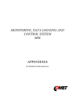
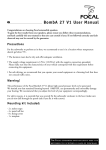
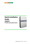
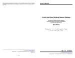
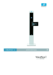
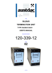
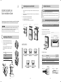
EN
Original Version
SG30KTL/SG30KTL-M
Quick Installation Guide
2
i.
Select the installation location and regulate the clearances of multiple inverters, referring to the
user manual.
ii.
Move the inverter to the installation site with the help of another person or the lifting device by
means of the handles.
iii.
This guide provides a general instruction of the installation procedures of SG30KTL and SG30KTL-M.
3
Mounting Inverter onto the Wall
Install the inverter onto wall as following procedures.
Electrical Connection
Death hazards due to high voltage existing inside the inverter!
Make sure that all the DC and AC cables to the inverter are not live before you start the electrical
work.
Do not turn on the AC side or DC side circuit breaker until all inverter electrical connections have
completed.
a. Fix the backplate on the wall with appropriate fixing sets.
b. Assemble the top cap of the inverter.
c. Mount the inverter onto the backplate and secure it with M4 screws.
Neither the DC positive pole nor the DC negative pole of the PV string is permitted to be grounded.
SG30KTL and SG30KTL-M will be referred to as inverter hereinafter unless otherwise specified.
Attach the backplate to the wall
Hang and secure the inverter
Assemble cap
2
In no case shall this guide substitute for the user manual or related notes on the device.
Make sure to read over, fully understand and strictly follow the detailed instructions of the
user manual and other related regulations before installing the equipment.
Any violation could result in personal death or injury or device damage.
1
i.
ii.
1
Recommended PV Array Open Circuit Voltage(25℃)
3-1 Open the Connection Cabinet
1
Loose the six screws on the front cover of the connection
cabinet and remove the front cover to see the internal
layout of the connection cabinet.
PV input terminals
Unpack the carton and take out all the accessories.
Inspect the inverter for visible damages and check
the completeness of the delivery contents according
to the inner packing list.
Name
Backplate
2
Top cap
3
SG30KTL/SG30KTL-M
4
Documents & Accessories
AC cable gland
DC
Cool air
520
mm
Contact your supplier if any of the contents is missing.
SG30KTL/SG30KTL-M is unavailable if any damage is
detected.
1
Bottom terminals
Communication cable gland
Unpacking and Inspection
No.
700…850V
2
970mm
Hot air
822mm
3-2 Cables Selection
1000mm
600mm
1000mm
600mm
Cable
AC Cable
1
Recommended
conductor size
Conductor size
8AWG...5AWG
8...16mm2
7AWG
10mm2
12AWG...10AWG
4...6mm2
11AWG
4mm2
2
DC Cables
3
RS485 Comm. Cables
Twist-pair type cable or Twist-pair type shielding Ethernet cable
4
Second PE Cable
10AWG…8AWG
600mm
1000mm
600mm
AC cable
6mm2
9AWG
PE
Φ6mm…9mm
L1
L2
11AWG(4mm2)
+
-
L3
18mm
EN-1
EN-2
6mm2
DC cable
7AWG(10mm2)
Φ22mm…27mm
-
7mm
N
EN-3
4
Second PE Connection
Pull the cables and connect L1/L2/L3/N/PE cables ends to
the corresponding terminal blocks.
Item
Description
Remark
A
Screw
M4×12mm
B
Lock washer
-
C
Washer
-
D
Cable socket
-
E
Yellow-green cable
6mm2(9AWG)
Commissioning
Beforestartingtheinverter,makesureallinstallationandconnectionsarecompletedandverified.
Step 1
Step 2
Step 3
*The connection parts are not included in the delivery scope.
Close the external AC circuit breaker.
Rotate DC switch to the “ON” position.
Supported that there is sufficient sunlight and DC power, the inverter begins to initialize and the LCD is
activated to setup the interface. Press buttons to configure initial inverter parameters.
Button
SG30KTL-M
3-4 DC Connection
3-4-1 Selecting PV configuration mode for SG30KTL-M
In the SG30KTL-M, the two PV inputs can be configured
in independent mode or parallel mode. Refer to the user
manual for an appropriate mode selection.
PV configuration mode can be performed by a switch on
the configuration circuit board.
3-7 Communication Connection
120Ω terminating
resistor switch
There are communication cable gland (RS485) at the bottom
of the inverter. Configuration circuit board has two optional
connection terminals: RS485 A/B terminal blocks and RJ45
plug-in terminals, and a 120 Ω terminating resistor switch.
Default
For independence mode: turn the switch ON.
For parallel mode: turn the switch OFF.
Description
Move upwards or downwards, or scroll to set value.
It is referred to as “Press ” hereinafter.
Press for more than two seconds
Return to parent menu or cancel the command.
It is referred to as “Press ESC” hereinafter .
Press for less than two seconds
Move left or right, or turn pages. It is referred to as
“Press ” hereinafter .
Press for more than two seconds
Enter into the sub-screen or confirm the command.
It is referred to as “Press ENTER” hereinafter.
Configuration circuit board
SetLanguage
RS485in RS485out
RS485bus
For SG30KTL, the switch must be set in parallel mode.
Operation
Press for less than two seconds
SetTime
RS485 RJ45
Deutsch
Française
When selecting parallel PV configuration mode, you should
connect DC1+ terminal to DC2 + with a cable of cross-section
not less than 6mm2 and connect DC1- to DC2- on the DC
connection circuit board.
DC1+
DC1-
DC2+
DC2-
Italia
For RJ45 Connection the pins definitions are shown below:
RJ45 plug
Corresponding Between Cables and
Pins:
Pin 1: White-orange;
Pin 2: Orange;
Pin 3: White-green;
Pin 4: Blue;
Pin 5: White-blue;
Pin 6: Green;
Pin 7: White-brown;
Pin 8: Brown.
12345678
3-4-2 Connection DC Cables
RS485+A
Assemble the DC plug-in connectors and connect them to
the bottom terminals.
Check the polarity of the PV input before PV input connection.
RS485-B
Pin 3 and Pin 6 are used for communication.
- Pin 3 to RS485- B
- Pin 6 to RS485+ A
Step 4
Inverter 2
120ohM
ON
Inverter 3
The inverter is equipped with second protective earth
terminal as specified in EN 50178.
A
120ohM
OFF
RS485
B
GND
A
RS485
B
Inverter n
120ohM
OFF
GND
A
RS485-1
RS485
B
120ohM
ON
G
GND
Time:
10:30:55
A
RS485
B
GND
ENTER
DE
FR
IT
ES
AT
AU
CZ
BE
DK
GR_L
GR_IS
NL
PT
CHN
SE
Other
When the initial configuration is completed, inverter will enter
into startup process. Observe the status of LED indicators and
the LCD main screen. If inverter‘s commissioning succeeds, the
“RUN” indicator will be lit and “RUN” will be displayed on the
“State” area.
Perform the following operation to set up the communication
address for the inverter.
Main screen (Press ENTER) →Menu screen(Press ×3) →
Set-param (Press ENTER) →Enter password(111111, Press
ENTER,Press ×3 ) →Com-param (Press ENTER)
Press to move cursor right and Press
value. Confirm by Press ENTER.
Second PE Terminals
P-ac
P[%]
1OO
25.8
E-day 1OO.5
75
5O
E-tot
4976OO
25
State
Run
8
14
2O
kW
kWh
kWh
t
90.1%
2012/01/31 1O:3O
Com-param
Address
OO1
to set the appropriate
The range of communication address is 1...247.
There is a second PE terminal on one side of the inverter.
You may choose to connect PE connection.
EN-4
12/01/31
If inverter’s commissioning fails, the “FAULT” indicator will be lit
and “FAULT” will occur on the display. Press to view “current
fault” information. Refer to the user manual for troubleshooting.
Repeat the above procedures for inverter commissioning.
Step 5
3-6 Second Protective Earth Terminal
Date:
GB
Only qualified personnel are allowed to adjust or setup parameters related to system protection
functions.
Multipleinvertersindaisychain
Inverter 1
ENTER
YY/MM/DD
中文
RJ45port
1---8
Countries
Format:
English
SG30KTL-M
ChooseCountry
Time
Languages
3-8 Completing Installation
Refer to the user manual for detailed instructions!
Inspect before commissioning and reassemble the front cover of the connection cabinet.
The images shown here are indicative only. The actual product may differ.
Specifications are subject to changes without advance notice.
EN-5
EN-6
SG30KTL_SG30KTL-M-QIEN-Ver11-201304 Version:1.1
QIEN F-H-001400
3-3 AC Connection