1
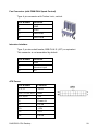
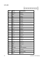
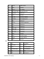
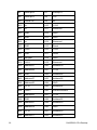
POS Motherboard D425/D525 CPU User Manual We would like to know your opinion on this publication. Please send us a copy of this page if you have any constructive criticism. We would like to thank you in advance for your comments. With kind regards, Your opinion: Wincor Nixdorf International GmbH Documentation RD HWD01 Wohlrabedamm 31 D-13629 Berlin E-Mail: [email protected] Order No.: 01750220414B (POS Motherboard with D425/D525 CPU) POS Motherboard D425/D525 CPU User Manual Edition June 2012 All brand and product names mentioned in this document are trademarks of their respective owners. Copyright © Wincor Nixdorf International GmbH, 2012 The reproduction, transmission or use of this document or its contents is not permitted without express authority. Offenders will be liable for damages. All rights, including rights created by patent grant or registration of a utility model or design, are reserved. Delivery subject to availability; technical modifications possible. Refer to protection notice ISO 16016 Contents Introduction ................................................................................................. 9 Basic Features of the D425/D525 Motherboard ...................................... 10 Processors .................................................................................................. 10 Features ...................................................................................................... 10 Motherboard Specification ....................................................................... 11 Blockdiagram of D425/D525 Motherboard .................................................. 11 Motherboard Mechanical Arrangement ....................................................... 12 Motherboard PCB Dimension...................................................................... 12 External I/O Connector................................................................................ 13 Internal I/O Connector ................................................................................. 13 Jumper Setting ............................................................................................ 14 Power Consumption of D425/D525 Motherboard........................................ 14 Maximum Current Rating for External Peripherals ...................................... 15 Supported Power Modes (Sx) ..................................................................... 15 Thermal Management ................................................................................. 15 CPU Support ............................................................................................... 16 Memory Support.......................................................................................... 16 Graphics Subsystem ................................................................................... 16 System Clock Generator ............................................................................. 17 Fast Ethernet LAN Interface........................................................................ 17 Super I/O Controller .................................................................................... 17 SATA II Interface ......................................................................................... 18 IDE Interface ............................................................................................... 18 CPU Fan and System Fan........................................................................... 18 Audio ........................................................................................................... 19 USB Interface .............................................................................................. 19 Serial Interfaces COM1-5 ............................................................................ 20 Parallel Port................................................................................................. 20 PS/2 Keyboard and Mouse Interface........................................................... 20 Front Panel Interface................................................................................... 20 Cash Drawer Interface ................................................................................ 21 Cash Drawer Interface I/O 310h ............................................................. 21 Intrusion Detect Interface ............................................................................ 21 TPM............................................................................................................. 21 System Beeper............................................................................................ 21 Connector and Pin Assignments ............................................................. 22 External Connectors.................................................................................... 22 PS/2 Keyboard and Mouse Connector.................................................... 22 Fast Ethernet LAN Connector ................................................................. 22 USB Connectors ..................................................................................... 23 COM1 Connector .................................................................................... 23 COM2*-5* Connectors ............................................................................ 24 Type: DSUB-9 pin ................................................................................... 24 VGA Connector ....................................................................................... 25 Audio Connector ..................................................................................... 25 LPT Connector........................................................................................ 26 Connectors and Headers for internal Connection........................................ 27 SATA....................................................................................................... 27 USB Header............................................................................................ 27 Front Panel Interface Connector ............................................................. 28 Cash Drawer Interface Connector........................................................... 28 Fan Connector (with PWM FAN Speed Control)..................................... 29 Intrusion Interface ................................................................................... 29 ATX Power.............................................................................................. 29 PATA IDE................................................................................................ 30 PCI .......................................................................................................... 31 Technical Data ........................................................................................... 35 Changing the Battery ................................................................................ 37 Addendum.................................................................................................. 38 Sleep States............................................................................................ 38 LED LAN (RJ45) ..................................................................................... 38 BIOS Setup................................................................................................. 39 Standard BIOS Version ............................................................................... 39 BIOS Menu Bar....................................................................................... 40 Legend Screen........................................................................................ 40 General Help........................................................................................... 41 Scroll Bar ................................................................................................ 41 Sub-Menu ............................................................................................... 41 Info Screen .................................................................................................. 42 Product Name ......................................................................................... 42 BIOS Version .......................................................................................... 43 MAC Address.......................................................................................... 43 UUID Info ................................................................................................ 43 System, Main board, Power Supply ........................................................ 43 Main Menu................................................................................................... 43 System Time [XX: XX: XX]...................................................................... 43 System Date [XX/XX/XXXX] ................................................................... 44 Advanced Menu........................................................................................... 44 Sub Menu Hardware Monitoring.......................................................... 44 Sub Menu SuperIO Information........................................................... 45 Sub Menu CPU Configuration ............................................................. 46 Sub Menu IDE Configuration............................................................... 47 Sub Menu USB Configuration ............................................................. 49 Sub Menu > Hardware Control ............................................................... 50 Sub Menu North Bridge Configuration ................................................ 53 Boot Menu ................................................................................................... 53 Boot Settings Configuration .................................................................... 54 Bootup Num-Lock [On] ........................................................................... 54 PS/2 Mouse Support [Auto] .................................................................... 54 Security Menu ............................................................................................. 55 Change Supervisor Password ................................................................ 55 Change User Password .......................................................................... 55 Intrusion Detection [Disabled] ................................................................. 55 Exit Menu .................................................................................................... 56 Save Changes and Exit .......................................................................... 56 Discard Changes and Exit ...................................................................... 56 Discard Changes .................................................................................... 56 Load Defaults.......................................................................................... 57 Test Points Codes ....................................................................................... 57 Bootblock Initialization Code Checkpoints................................................... 57 POST Code Checkpoints ............................................................................ 58 Boot Block Beep Codes .............................................................................. 60 POST BIOS Beep Codes ............................................................................ 60 Troubleshooting POST BIOS Beep Codes.................................................. 60 Abbreviations ............................................................................................ 61 User Manual POS Motherboard D425/D525 CPU Introduction This User Manual describes the features of a Motherboard based on the INTEL D425/D525 processor and ICH8M chipset in mITX form factor. This new D425/D525 Motherboard is designed for Wincor Nixdorf’s BEETLE /i8A, BEETLE / SII+ family and BEETLE /mini. D425/D525 Board No Amplifier onboard Cash drawer support onboard Fast Ethernet 100Mbit Target system: B/SII+, B/i8A-3, B/mini D425/D525-CPU-Desktop 9 Basic Features of the D425/D525 Motherboard Processors The features of the motherboard based on the INTEL D425/D525 processor and ICH8M chipset in mITX form factor. Features 10 Intel ATOM processor D425 (single core), 1.8GHz/ Intel ATOM processor D525 (dual core), 1.8GHz Integrated Intel 3rd Gen Graphics Core 1 VGA HDD SATA II interface (2 ports) HDD PATA interface 44 pin for compact flash module Supports chassis fan with automatic PWM speed control Fast Ethernet 100Mbit LAN onboard One DDR3 SDRAM (SO-DIMM) socket, up to 2GB / 800MHz supported One PCI slot supporting SMBUS 5 COM ports (4 ports have the option to be powered COM) 8 USB ports 1 Cash drawer Altera CPLD onboard Intel HD audio controller with microphone, line in and line out connectors NVRAM module support via PCI riser card OS support includes Windows 7 Long term availability for 5 years (Intel embedded roadmap) D425/D525-CPU-Desktop Motherboard Specification Blockdiagram of D425/D525 Motherboard Block Diagram VRD 11 ISL6314 1-Phase PWM Clock REALTEK RTM875T-531 System Power RT8207 RT9018 RT9199 Intel ATOM Processor D425 /D525 DDR3 800 Analog Video (VGA) RGB 1 DDR III SODIMM Module DMI DDRIII PCI Slot 44pin IDE PCI (33MHz, 32bit) HD Audio Link ICH8M PATA IDE PCIe x1 SATA-II 1,2 SATA2 USB Port 1~8 USB2.0 HD Audio Codec ALC262 LAN REALTEK RTL8105E SPI Flash ROM D425/D525-CPU-Desktop LPC SPI Cash Drawer 5M40ZE64 LPC SIO ITE IT8783F 4 COM* 1 COM PS/2 KEYBOARD LPT 11 Motherboard Mechanical Arrangement Motherboard PCB Dimension D425/D525 motherboard (including I/O shield) follows mITX standard and therefore PCB mechanical dimension is 170mm x 170mm. 12 D425/D525-CPU-Desktop External I/O Connector External I/O connectors are arranged as illustrated here: LAN/USB K/M/USB AUDIO VGA LPT COM1 Interface Connector-Type COM1 9 pin D-sub male LPT 25 pin D-sub female Keyboard, Mouse, USB 6 pin Mini Din + stacked dual USB series A LAN, USB RJ45 Ethernet + stacked dual USB series A VGA 15 pin HDD-sub female AUDIO Line Out 3,5 mm female AUDIO Line In 3,5 mm female AUDIO Microphone 3,5 mm female Internal I/O Connector Interface Connector-Type DDR3 SO-DIMM 1pcs 204 pin micro edge connector PATA IDE 1pcs 44 pin header, 2mm (425 only) Hard disk (SATA) 2pcs 7 pin Standard SATA headers 3.3V, 5V, 12V Supply ATX 20 pin power connector USB port 4-8 2pcs 2x5 pin headers, 2.54 mm D425/D525-CPU-Desktop 13 COM* 2-5 4pcs 2x7 pin headers (2.0mm shrouded) FAN 2pcs 4 pin PCI 1x standard PCI connector Front panel 1pcs 2x6 pin header, 2.54mm Chassis intrusion 1pcs 3 pins header (2.0mm shrouded) Cash drawer 1pcs 6 pins header (2.0mm shrouded) Jumper Setting Jumper Connector-Type Setting JP1 CMOS clear 1-2 default, 2-3 CMOS clear Power Consumption of D425/D525 Motherboard D425/D525 motherboard is powered by 3.3V, 5V, 5Vstby, 12V and -12V from a standard ATX power supply. The maximum current is specified as follows, this does not include external connected peripherals. 14 Voltage I max P 3.3V 1A 3.3W 5V 1A 5W 5VSB 0.5A 2.5W 12V 1.5A 18W -12V 0.1A 1.2W D425/D525-CPU-Desktop Maximum Current Rating for External Peripherals Interface Voltage I max Powered COM (COM 2-5 total) 5V 1A Powered COM single port 5V 0.3A Powered COM (COM 2-5 total) 12V 1A Powered COM single port 12V 0.6A USB, single port 5V 0.5A USB, all ports total 5V 2A PS/2 5V 0.5A DVI, VGA 5V 0.1A Supported Power Modes (Sx) D425/D525 Motherboard supports power states S0, S3, S4 and S5. Wake up events from sleep states are supported from USB ports, COM1 ring indicator, internal CMOS clock, PS2 Keyboard and Ethernet. Power management supports ACPI 3.0 and APM1.2. Thermal Management st D425/D525 Motherboard supports 2 FAN connectors. The 1 FAN connector nd is reserved for CPU fan. The 2 FAN connector is connected to power supply fan and detects it’s rotating speed. Supported CPUs and it’s TDP and maximum junction temperature: CPU TDP Idle power Max Tj D425 10W 4W typ. 100 °C D525 13W 4.8W typ. 100 °C ICH8M 3W 2W D425/D525-CPU-Desktop 15 CPU Support Due to the fact Atom CPU comes in a BGA package it is soldered to PCB and can not be changed. Processor Core Clock Speed Footprint Max TDP D425 1 1.8GHz FCBGA559 10W D525 2 1.8GHz FCBGA559 13W Memory Support The motherboard has one SO-DIMM socket supporting single channel, unbuffered, no ECC DDR3 SDRAM. Memory size of 1GB and 2GB. DIMM Capacity DRAM Device Technology DRAM Organization Ranks 1GB 1GB 64M X 16 2 2GB 2GB 128M X 16 2 1GB 1GB 128M X 8 1 2GB 2GB 256M X 8 1 The motherboard supports the following memory features: 667 / 800 MHz unbuffered SDRAM SO-DIMM Non-ECC 1.5V voltage rating BIOS automatically detects memory type, size, and speed If higher frequency memory modules than 800MHz are used, the frequency will be limited to 800MHz automatically. Graphics Subsystem Graphics support is via the internal graphics accelerator of the D425/D525 processor to provide single display. 16 D425/D525-CPU-Desktop Main features of integrated GPU are: ® Intel Dynamic Video Memory Technology support 4.0, up to 384MB Directx 9 compliant Pixel Shader v2.0 400 MHz render clock frequency Intel Clear Video Technology MPEG2 Hardware Acceleration ProcAmp ® ® ® The analogue VGA port utilizes an integrated 350MHz RAMDAC capable of driving a standard progressive scan monitor resolution up to 2048 x 1536 at 60Hz. Signal Voltage level R,G,B 0.7VP-P @75OHM HSYNC, VSYNC 5.0V DDC CHANNEL OPEN DRAIN, 5.0V TOLERANT System Clock Generator The clock generator is conforming to CK505 specification and made by nd Realtek RTM875T-531. As 2 source ICS9LPRS511 is available. Fast Ethernet LAN Interface Fast Ethernet LAN interface is provided through PCI-e based Ethernet Controller by Realtek RTL8105E. Super I/O Controller Super I/O controller IT8783 from ITE provides the following functions: Five 16C550 UARTs PS/2 keyboard and mouse controller Two automatic fan speed controller D425/D525-CPU-Desktop 17 Two tachometer inputs Hardware monitor SATA II Interface The ICH8M has three integrated SATA host controller that supports independent DMA operation and data transfer rates up to 3.0Gb/s. SATA Port ICH8M Usage on Motherboard Port #0 Port #1 Port #2 On-board connector Not connected On-board connector IDE Interface D425/D525 Motherboard provides a standard PATA IDE 44 pin interface intended for CF interface. CPU Fan and System Fan D425/D525 motherboard supports automatic fan speed control by pulse width modulation (PWM, 4pin fan connector). If a 3 pin fan is used (BEETLE /mini) there is no rpm control. The 2nd CPU fan connector FAN2 is indented to sense power supply fan. System FAN connector Used as BEETLE /SII+ FAN1 Not used FAN2 Power supply FAN1 Not used FAN2 Power supply FAN1 CPU fan FAN2 Not used BEETLE /i8A BEETLE /mini 18 D425/D525-CPU-Desktop Audio An INTEL HD Audio Link is provided thru ICH8M. It is used with a Realtek HD Audio Codec ALC662 providing a low cost solution. In case of EOL the ALC262 is prepared for AVL use. Supported interfaces are: Line-out Mic-in Line-in USB Interface The ICH8M contains two EHCI compliant host controller that support USB high speed signalling. High speed USB 2.0 allows data transfers up to 480Mb/s. The ICH8M also contains five UHCI controller that support USB full speed and low speed signalling. EHCI ICH8M Port Connection on Motherboard 0 USB1 connector pin 1,3,5,7 1 USB1 connector pin 2,4,6,8 2 USB2 connector pin 1,3,5,7 3 USB2 connector pin 2,4,6,8 4 PS/2 / USB connector upper port 5 PS/2 / USB connector lower port 6 LAN / USB connector lower port 7 LAN / USB connector upper port 8 Not used 9 Not used D425/D525-CPU-Desktop 19 Serial Interfaces COM1-5 D425/D525 Motherboard provides five serial ports. COM1 is the standard serial interface. On the DSUB-9 pin male connector all signals are available including the modem signals RI and DCD. The I/O assignments of the powered serial ports (COM2* to COM5*) deviate from the standard as it is equipped with system voltage of +5V and +12V instead of the signals RI and DCD. These serial ports are routed to 2x7 pin headers (2.0mm shrouded) and to DSUB-9 pin female connectors (via cables). All serial ports comply with RS-232 signalling level voltage. Parallel Port D425/D525 motherboard supports a parallel port according to IEEE1284. PS/2 Keyboard and Mouse Interface The keyboard and mouse controller is part of the Super I/O chip. The PS/2 interface is available on a Mini DIN connector. Front Panel Interface The motherboard provides a front panel interface, supporting the following features: 20 Power ON/OFF button Reset button Status LED, showing Active (Green), Standby (Green, flashing), Shutdown (Red), HDD Activity (Amber, flashing) System beeper D425/D525-CPU-Desktop Cash Drawer Interface Cash Drawer Interface I/O 310h This Cash Drawer interface is provided thru a 6pin shrouded header. From this header a cable goes to the power supply where the cash drawer output is located. Reading of I/O address 310h gets back status of cash drawer and power button. A 1 indicates an open cash drawer. A 0 indicates a closed or not connected cash drawer. 7 6 5 CD2 CD1 PB 4 x 3 x 2 x 1 x 0 x Writing a 1 to address 310h bit 6 or 7 initiate a 500ms active low signal on the cash drawer output 1 or 2. Writing 1 to both bits at the same time is not supported by hardware. In this case both outputs stay inactive. Intrusion Detect Interface D425/D525 Motherboard supports an intrusion detect interface. This is a 3pin shrouded header. TPM D425/D525 Motherboard is prepared for TPM IC. This feature is not assembled. System Beeper D425/D525 Motherboard supports a system beeper interface connector. This is part of the front panel interface. D425/D525-CPU-Desktop 21 Connector and Pin Assignments External Connectors PS/2 Keyboard and Mouse Connector ConnectorType: Mini-DIN Female Pin Number Function 1 KB Data 2 GND 3 +5V 4 KB Clock 5 MS Data 6 MS Clock Fast Ethernet LAN Connector Type: RJ45 connector (Stacked LAN + USB Connector) 22 Pin Number Function 1 Bi-directional Pair A+ 2 Bi-directional Pair A- 3 Bi-directional Pair B+ 4 Not used 5 Not used 6 Bi-directional Pair B- 7 Not used 8 Not used D425/D525-CPU-Desktop USB Connectors Type: Stacked USB Type A Connector, male (Stacked LAN + USB Connector) Pin Number Function 1 Fused +5V 2 USB D- 3 USB D+ 4 GND COM1 Connector Type: DSUB-9 pin, male Pin Number Function 1 DCD - Data Carrier Detect 2 RXD - Serial Data In 3 TXD - Serial Data Out 4 DTR - Data Terminal Ready 5 GND 6 DSR - Data Set Ready 7 RTS - Request To Send 8 CTS - Clear to Send 9 RI - Ring Indicator D425/D525-CPU-Desktop 23 COM2*-5* Connectors Connector type: 2x7 pin header JST B14B-PHDSS or similar Pin Number Function 1 +5V 2 GND 3 DCD - Data Carrier Detect 4 GND 5 CTS - Clear to Send 6 DTR - Data Terminal Ready 7 RTS - Request To Send 8 TXD – Serial Data Out 9 DSR - Data Set Ready 10 RXD - Serial Data In 11 RI - Ring Indicator 12 GND 13 +12V 14 GND Type: DSUB-9 pin Female (Tyco P/N: 5747844-4) 24 Pin Number Function 1 +12V 2 RXD - Serial Data In 3 TXD - Serial Data Out 4 DTR - Data Terminal Ready 5 GND 6 DSR - Data Set Ready 7 RTS - Request To Send 8 CTS - Clear to Send 9 +5V D425/D525-CPU-Desktop VGA Connector Type: DSUB-15 pin, DSUB-15 female Pin Number Function 1 RED 2 GREEN 3 BLUE 4 n.c. 5 GND 6 GND 7 GND 8 GND 9 +5V 10 GND 11 n.c. 12 DDC SDA 13 HSYNC 14 VSYNC 15 DDC SCL Audio Connector Type: Stacked Audio Jack Port Number Function Top Line out Middle Line In Bottom Microphone In D425/D525-CPU-Desktop 25 LPT Connector 26 Pin Number Function 1 /STROBE 2 D0 Data Bit 0 3 D1 Data Bit 1 4 D2 Data Bit 2 5 D3 Data Bit 3 6 D4 Data Bit 4 7 D5 Data Bit 5 8 D6 Data Bit 6 9 D7 Data Bit 7 10 /ACK Acknowledge 11 Busy 12 PE Paper End 13 SEL Select 14 /AUTOFD Autofeed 15 /ERROR Error 16 /INIT Initialize 17 /SELIN Select In 18-25 GND D425/D525-CPU-Desktop Connectors and Headers for internal Connection SATA Type: 7 pin SATA connector, LD180F-S16P (Foxconn) or equivalent. Pin Number Function 1 GND 2 TXP 3 TXN 4 GND 5 RXN 6 RXP 7 GND USB Header Type: 2x5 pin headers, 2.54mm pitch. Pin Number Function 1 +5V 2 +5V 3 D- 4 D- 5 D+ 6 D+ 7 GND 8 GND 9 Key 10 GND D425/D525-CPU-Desktop 27 Front Panel Interface Connector Type: 2x6 pin header, 2.54mm pitch Pin Number Function 1 Power switch + 2 Reset switch + 3 Power switch - 4 Reset switch - 5 Power LED + 6 Speaker - 7 Power LED - 8 Coding Key 9 HDD LED + 10 GND 11 HDD LED - 12 Speaker + Cash Drawer Interface Connector Type: 6 pin shrouded header 28 Pin Number Function 1 +5V 2 CD out 1 3 CD status 1 4 CD out 2 5 CD status 2 6 nc. D425/D525-CPU-Desktop Fan Connector (with PWM FAN Speed Control) Type: 4 pin connector with Friction Lock, vertical. Pin Number Function 1 GND 2 +12V 3 FAN RPM 4 FAN PWM Intrusion Interface Type: 3 pin shrouded header, B3B-PH-K-S (JST) or equivalent. This connector is not assembled by default. Pin Number Function 1 GND 2 Intrusion input 3 n.c. ATX Power Pin Number Function 1,2,11 +3.3V 3,5,7,13,16,16,17 GND 4,6,19,20 +5V 8 Power ok 9 5V SB 10 +12V 12 -12V 14 PSON D425/D525-CPU-Desktop 29 PATA IDE 30 Pin Name Description 1 /RESET Reset 2 GND Ground 3 DD7 Data 7 4 DD8 Data 8 5 DD6 Data 6 6 DD9 Data 9 7 DD5 Data 5 8 DD10 Data 10 9 DD4 Data 4 10 DD11 Data 11 11 DD3 Data 3 12 DD12 Data 12 13 DD2 Data 2 14 DD13 Data 13 15 DD1 Data 1 16 DD14 Data 14 17 DD0 Data 0 18 DD15 Data 15 19 GND Ground 20 KEY Key 21 DMARQ DMA Request 22 GND Ground 23 /DIOW Write Strobe 24 GND Ground D425/D525-CPU-Desktop 25 /DIOR Read Strobe 26 GND Ground 27 IORDY I/O Ready 28 SPSYNC:CSEL Spindle Sync/CS 29 /DMACK DMA Ack. 30 GND Ground 31 INTRQ Interrupt Request 32 /IOCS16 IO ChipSelect 16 33 DA1 Address 1 34 PDIAG Passed Diagnostics. 35 DA0 Address 0 36 DA2 Address 2 37 /IDE_CS0 (1F0-1F7) 38 /IDE_CS1 (3F6-3F7) 39 /ACTIVE Led driver 40 GND Ground 41 +5VL +5 VDC (Logic) 42 +5VM +5 VDC (Motor) 43 GND Ground PCI B1 -12V A1 TestReset B2 TestClock A2 +12V B3 GND A3 TestModeSelect B4 TestDataOutput A4 TestDataInput B5 +5V A5 +5V B6 +5V A6 Interrupt A D425/D525-CPU-Desktop 31 32 B7 Interrupt B A7 Interrupt C B8 Interrupt D A8 +5V B9 PRSNT1# A9 nc. B10 nc. A10 +VI/O B11 nc. A11 Reserved B12 GND A12 GND B13 GND A13 GND B14 nc. A14 Reserved B15 GND A15 Reset B16 Clock A16 +VI/O B17 GND A17 Grant B18 Request A18 GND B19 +VI/O A19 Reserved B20 Address31 A20 Address30 B21 Address29 A21 +3.3V B22 GND A22 Address28 B23 Address27 A23 Address26 B24 Address25 A24 GND B25 +3.3V A25 Address24 B26 C/BE3 A26 InitDeviceSelect B27 Address23 A27 +3.3V B28 GND A28 Address22 B29 Address21 A29 Address20 B30 Address19 A30 GND B31 +3.3V A31 Address18 B32 Address17 A32 Address16 D425/D525-CPU-Desktop B33 C/BE2 A33 +3.3V B34 GND A34 CycleFrame B35 InitiatorReady A35 GND B36 +3.3V A36 TargetReady B37 DeviceSelect A37 GND B38 GND A38 Stop B39 Lock A39 +3.3V B40 ParityError A40 SMB clock B41 +3.3V A41 SMB data B42 SystemError A42 GND B43 +3.3V A43 PAR B44 C/BE1 A44 Address15 B45 Address14 A45 +3.3V B46 M66EN/Ground A46 Address13 B47 Address12 A47 Address11 B48 Address10 A48 GND B49 GND A49 Address9 B52 Address8 A52 C/BE0 B53 Address7 A53 +3.3V B54 +3.3V A54 Address6 B55 Address5 A55 Address4 B56 Address3 A56 GND B57 GND A57 Address2 B58 Address1 A58 Address0 B59 +5V A59 +5V B60 Acknowledge64-bit A60 Request64-bit D425/D525-CPU-Desktop 33 34 B61 +5V A61 +5V B62 +5V A62 +5V D425/D525-CPU-Desktop Technical Data Microprocessor Intel ATOM Processor D425 (single core), 1.8GHz Intel ATOM Processor D525 (dual core), 1.8GHz Supported Systems BEETLE /SII+, BEETLE /i8A, BEETLE /mini Architecture mITX form factor Chipset ICH8M, supporting SATA II controller, USB UHCI and EHCI controller, Interrupt controller, DMA controller, LPC interface, RTC, SMBUS host interface, PCI, Intel High Definition Audio interface, SPI Super I/O IT8783, supporting 5 UARTS, PS/2 keyboard and mouse interface, LPT, automatic fan speed controller, hardware monitor Ethernet Controller PCI-e based Realtek RTL8105E (10/100MBit), PXE Wake On Feature Wake-on-LAN, Wake-on-time, Wake-on-USB, Wake-on-PS/2, Wake-on-modem Sound Controller Audio Codec with line out, line-in and mic-in connectors in I/O shield Cash Drawer onboard CPLD for cash drawer, additional 6 pin JST connector for direct connection to cash drawer integrated in power supply NVRAM supported thru PCI riser card Main Memory 1x SO-DIMM, 1GB up to 2GB DDR3 SDRAM technology, based on 1Gb / 2Gb technology, unbuffered non-ECC running at 667 or 800MHz BIOS SPI Flash, 8Mb, AMI BIOS, with customization for BEETLE systems, PnP 1.1, ACPI, DMIsupport Keyboard PS/2 connection onboard in I/O shield, supporting Y-cable for Mouse support D425/D525-CPU-Desktop 35 36 Serial Interfaces COM1 onboard in I/O shield, DSUB-9 pins male connector, all other onboard 2x7 pin headers supporting powered COM LPT onboard in I/O shield, supporting SPP, EPP, ECP USB USB2.0, up to 8 ports. USB 1, 2 – 2 ports stacked connector, series A in I/O shield (together with PS/2), USB 3,4 – 2 ports stacked connector, series A in I/O shield (together with LAN), all other – Internal 2x5 pin headers Status Display supports LED (ON, Standby, OFF, HDD) activities, power and reset button (front panel connector) HDD, ODD connection SATA II interface (3.0Gb/s) and 44 pin RM2 standard PATA PCI slot 32bit, 33MHz, PCI2.2, with riser card support and SMBUS Video out VGA only Battery for RTC and Super-I/O, Type: CR2032, 220mAh Fuses poly switches for +5V of powered COM, all USB (2 ports sharing one fuse), PS/2, VGA, +12V of powered COM I/O Shield Connectors stacked USB and PS/2 keyboard + mouse, VGA, stacked USB and LAN, standard COM1, audio (MIC in, line in, line out), LPT Internal Connectors 1x DDR3 SO-DIMM socket, 2x internal SATA connector, 1x HDD/CF IDE docking connector, 2x USB (2 ports each), 4x powered COM 2x7 pin headers, 2x 4 pin fan connector supporting fan speed control thru PWM, front panel interface, cash drawer interface, header for intrusion detect Board Dimension 170.0mm x 170.0 mm D425/D525-CPU-Desktop Changing the Battery The BEETLE POS systems are equipped with a lithium battery on the motherboard (see page 13) to ensure data retention, the time and the setup parameters. The battery should be changed approximately every five years. When inserting the new battery, make sure the polarity is correct. This is marked in the socket. Incorrect replacement of the battery may lead to the danger of explosion. The battery is located in a socket on the Motherboard. To gain access to the battery, proceed as described in the according chapters of your BEETLE User Manual. See: http://www.wincor-nixdorf.com/internet/site_EN//EN/Support/Downloads/ POSLotterySystems/Manuals/manuals_node.html The lithium battery must be replaced only by identical batteries or types recommended by Wincor Nixdorf International. You can return the used batteries to your Wincor Nixdorf International sales outlet. Batteries containing harmful substances are marked accordingly. The chemical denotations are as follows: CD = Cadmium; Pb = Lead, Li = Lithium. This symbol on a battery tells you that batteries containing harmful substances must not be disposed of as household waste. Follow the country specific laws and regulations. Within the European Union you are legally bound to return these batteries to the service organization where you purchased the new battery. The setup parameters must be reset each time the battery has been changed. D425/D525-CPU-Desktop 37 Addendum Sleep States S0 Normal operation (“On”) S3 Suspend to RAM / “Stand By” S4 Suspend to Disk / “Hibernation” S5 Soft Off LED LAN (RJ45) Left LED Right LED 38 Off 10 Mbit Constantly green 100 MBit Constantly yellow Connection to network Blinking yellow Data transfer D425/D525-CPU-Desktop BIOS Setup The D425/D525-CPU main board is equipped with an AMI BIOS chip that contains the ROM Setup information of your system. This chip serves as an interface between the processor and the rest of the main board components. This section explains the information contained in the Setup program and tells you how to modify the settings according to your system configuration. Even if you are not prompted to use the Setup program, you might want to change the configuration of your system in the future. For example, you may want to enable the Security Password Feature or make changes to the power management settings. It will then be necessary to reconfigure your system using the BIOS Setup program so that the system can recognize these changes and record them in the CMOS RAM or the FLASH ROM. All setup data is stored in a non volatile memory (CMOS RAM). When you remove the CMOS battery all parameters will be lost. Standard BIOS Version The BIOS ROM of the system holds the Setup utility. When you turn on the system, it will provide you with the opportunity to run this program. This appears during the Power-On Self Test (POST). Press <F2> to call the Setup utility. If you are a little bit late pressing the mentioned key, POST will continue with its test routines, thus preventing you from calling Setup. If you still need to call Setup, reset the system by pressing <Ctrl> + <Alt> + <Del>. You can also restart by turning the system off and then on again. But do so only if the first method fails. If you like to change the boot order only once, you can press the <F10> key during the POST is running. At the end you will see a Pop-Up window with all the devices the system is finding. With the keys <UP> and <DOWN> you select the boot device. The Setup program has been designed to make it as easy as possible. It is a menu-driven program, which means you can scroll through the various sub-menus and make your selections among the predetermined choices. D425/D525-CPU-Desktop 39 When you invoke Setup, the main program screen will appear. Read more about the Setup entries on the following pages. Because the BIOS software is constantly being updated, the following BIOS screens and descriptions are for reference purposes only and may not reflect your BIOS screens exactly. BIOS Menu Bar The top of the screen has a menu bar with the following sections: INFO Use this menu for information only MAIN Use this menu to make changes to the basic system configuration. ADVANCED Use this menu to enable and make changes to the advanced features. BOOT Use this menu to configure the default system device used to locate and load the Operating System. SECURITY Use this menu to enable a supervisor or user password and Intrusion Detection. EXIT Use this menu to exit the current menu or specify how to exit the Setup program. To access the menu bar items, press the right or left arrow key on the keyboard until the desired item is highlighted. Legend Screen The right frame displays the key legend. The keys in the legend frame allow you to navigate through the various setup menus. The following table lists the keys found in the legend with their corresponding alternates and functions. 40 D425/D525-CPU-Desktop Navigation Key(s) Description of Functions or (keypad arrows) Select the menu item to the left or right. or (keypad arrows) Moves the highlight up or down between fields. + (plus key) - (minus key) Change field contents. <Tab> Jumps from one field to the next. <F1> Opens a general Help Screen with extended informations. <F10> Saves changes and exits Setup. <Esc> Opens a windows to select between exit and return to setup General Help In addition to the Item Specific Help window, the BIOS setup program also provides a General Help screen. This screen can be called from any menu by simply pressing <F1>. The General Help screen lists the legend keys with their corresponding alternates and functions. Scroll Bar When a scroll bar appears to the right of a help window, it indicates that there is more information to be displayed that will not fit in the window. Use <PgUp> and <PgDn> or the up and down keys to scroll through the entire help document. Press <Home> to display the first page, press <End> to reach the last page. To exit the help window, press the <Enter> or <Esc> key. Sub-Menu Note that a right pointer symbol “” appears left of certain fields. This pointer indicates that a sub-menu can be launched from this field. A submenu contains additional options for a field parameter. To call a sub-menu, simply move the highlight to the field and press <Enter>. D425/D525-CPU-Desktop 41 The sub-menu then will appear immediately. Use the legend keys to enter values and move from field to field within a sub-menu just as you would do within a menu. Use the <Esc> key to return to the main menu. Take some time to familiarize yourself with each of the legend keys and their corresponding functions. Practice navigating through the various menus and sub-menus. If you accidentally make unwanted changes to any of the fields, use the set default hot key <F9>. While moving around through the Setup program, note that explanations appear in the Item Specific Help window located to the right side of each menu. This window displays the help text for the currently highlighted field. Info Screen When the Setup program is accessed, the following info screen appears: Product Name: BIOS Version: D425-CPU-STANDARD WN STD xx/yy mm/dd/yyyy MAC-Address: UUID Info: 00-21-05-16-EE-B2 FF-FF-FF-FF-FF-FF-FF-FF FF-FF-FF-FF-FF-FF-FF-FF System: ###---------------------------------------------------------------------------- Mainboard: -------------------------------------------------------------------------------- PwrSupply: -------------------------------------------------------------------------------- This screen is for information only. There is nothing that could be changed within Setup. All information is intended to facilitate the support of your system. Product Name This text is fixed for your mainboard with standard BIOS. This board is also called “D425-CPU-STANDARD”. 42 D425/D525-CPU-Desktop BIOS Version The BIOS version is displayed in the release format xx/yy, followed by date of release in international format. MAC Address The Ethernet MAC-Address of the Onboard LAN Controller is displayed at this line if [Enabled]. UUID Info A UUID is an identifier standard used in software construction, standardized by the Open Software Foundation. The intent of UUIDs is to enable distributed systems to uniquely identify information without significant central coordination. System, Main board, Power Supply The default placeholders may be replaced by specific data from factory, describing configuration, serial number etc. for each device. Main Menu System Overview Processor Intel (R) Atom(TM)2 CPU D425 Speed : 1800MHz Count : 1 @ 1.80GHz System Memory Size :2038MB System Time System Date [08:14:46] [10/31/2011] System Time [XX: XX: XX] Sets your system to the time that you specify (usually the current time). The format is hour, minute, second. Valid values for hour, minute, and second are: Hour: (00 to 23), Minute: (00 to 59), Second: (00 to 59). Press <Enter> to terminate every entry value and reach the next position. On the upper right frame find the keys listed to modify the values. D425/D525-CPU-Desktop 43 System Date [XX/XX/XXXX] Sets your system to the date that you specify (usually the current date). The format is month, day, year. Valid values for month, day and year are: Month: (1 to 12), Day (1 to 31), Year: (up to 2079). Advanced Menu Advanced Settings Hardware Monitoring SuperIO Information WARNING: Setting wrong values in below sections may cause system to malfunction. CPU Configuration IDE Configuration USB Configuration Hardware Control North Bridge Configuration Sub Menu Hardware Monitoring Hardware Monitoring 44 CPU Temperature Sensor Board Temperature Sensor 55°C/131°F 39°C/102°F CPU Speed PSU Speed N/A N/A CPU Core +1.50V +3.30V +5.00V +12.0V - 12.0V +1.05V VBAT 1.152 V 1.488 V 3.376 V 5.134 V 12.032 V -11.475 V 1.040 V 3.024 V D425/D525-CPU-Desktop CPU/Board Temperature Sensors [xx °C/xxx °F] The onboard hardware monitor is able to detect the motherboard and CPU temperatures (for supported processors only). Fan_CPU / PSU Speed [xxxx rpm] The onboard hardware monitor is able to detect the CPU fan speed and the power supply (PSU) fan speed in rotations per minute (rpm). Several Voltages [xx.x V] The onboard hardware monitor is able to detect the voltage output by the onboard voltage regulators. VBAT This Value shows the current state of CMOS Battery. A discharged battery will reported during the POST. Please change the battery according to the chapter “Changing the Battery”, see 29. Sub Menu SuperIO Information Display Ite8783 Super IO Configuration Serial Port1 Address Serial Port1 IRQ Serial Port2 Address Serial Port2 IRQ Serial Port3 Address Serial Port3 IRQ Serial Port4 Address Serial Port4 IRQ Serial Port5 Address Serial Port5 IRQ [3F8] [4] [2F8] [3] [3E8] [10] [2E8] [10] [2F0] [5] Parallel Port6 Address Parallel Port Mode ECP Mode DMA Channel Parallel Port IRQ [378] [ECP] [DMA3] [IRQ7] This setup screen shows the programmed values of the 5 onboard legacy serial ports and 1 parallel port. This is an on-screen information only (no options). D425/D525-CPU-Desktop 45 Sub Menu CPU Configuration Configure advanced CPU settings Manufacturer: Intel Intel (R) Atom(TM)2 CPU D425 Frequency :1.80GHz FSB Speed :800MHz Cache L1 :24 KB Cache L2 :512 KB Ratio Actual Value :9 Max CPUID Value Limit Execute-Disable Bit Capability Hyper Threading Technology Intel (R) SpeedStep (TM) tech Intel (R) C-STATE (TM) tech Enhanced C-States @ 1.80GHz [Disabled] [Enabled] [Enabled] [Disabled] [Enabled] [Enabled] The first lines lists information about the installed CPU. You can use this screen to select options for the CPU Configuration. The content of the CPU configuration setup screen varies depending on the installed processor. On the upper right frame you can see a short description of each changeable setup point. Max CPUID Value Limit Allows you to determine whether to limit CPUID maximum value. Set this item to [Disable] for Windows XP operating system, set this item to [Enabled] for legacy operating system. Configuration options: [Disabled] [Enabled] Execute-Disable Bit Capability Enable or disables Intel Execute Disable Bit function. This function may enhance protection for the computer, reducing exposure to viruses and malicious buffer overflow attacks when working with supporting software. Configuration options: [Disabled] [Enabled] Hyper Threading Technology Allows you to determine whether to enable the multi-threading function when using an Intel CPU that supports multi-threading technology. This feature only works for operating systems that supports multi-threading technology. Configuration options: [Disabled] [Enabled] 46 D425/D525-CPU-Desktop Intel (R) SpeedStep (TM) tech Allows you to determine whether to enable the SpeedStep function when using an Intel CPU that supports SpeedStep technology. This feature only works for operating systems that supports this technology. Configuration options: [Disabled] [Enabled] Intel (R) C-STATE (TM) tech Allows you to determine whether to enable the C-State technology function when using an Intel CPU that supports this technology. This feature reduces the internal CPU-Speed when system is in IDLE state. Configuration options: [Disabled] [Enabled] Enhanced C-States Allows you to determine whether to enable the Enhanced C-State technology function when using an Intel CPU that supports this technology. This feature reduces the internal CPU-Speed and disables the internal cache when system is in IDLE state. Configuration options: [Disabled] [Enabled] Sub Menu IDE Configuration IDE Configuration ATA/IDE Configuration Legacy IDE Channels [Compatible] [SATA Pri, PATA Sec] Primary IDE Master Primary IDE Slave Secondary IDE Master Secondary IDE Slave [Not Detected] [Not Detected] [Not Detected] [Not Detected] IDE Detect Time Out (Sec) [35] The onboard printed SATA port numbers have the following references to the setup entries: - SATA1 Primary IDE Master - SATA3 Primary IDE Slave ATA/IDE Configuration Configuration options: [Disabled] [Compatible] D425/D525-CPU-Desktop 47 [Compatible] With this option the second line below changed the text to: <Legacy IDE Channels> With this option the user has the choice to toggle between three IDE modes. SATA Only, SATA Primary, PATA Secondary or PATA only Primary IDE Master/Slave & Secondary IDE Master/Slave Primary IDE Slave Device :Hard Disk Vendor :TOSHIBA MK1637GSX Size :160.0GB LBA Mode :Supported Block Mode :16Sectors PIO Mode :4 Async DMA :MultiWord DMA-2 Ultra DMA :Ultra DMA-5 S.M.A.R.T. :Supported Type: LBA/Large Mode Block (Multi-Sector Transfer) PIO Mode DMA Mode S.M.A.R.T. 32Bit Data Transfer [Auto] [Auto] [Auto] [Auto] [Auto] [Auto] [Enabled] Note: Before attempting to configure a hard disk drive, make sure you have the configuration information supplied by the manufacturer of the drive. Incorrect settings my cause your system not to recognize the installed hard disk. To allow the BIOS to detect the drive type automatically, select [Auto]. Type [Auto] Select [Auto] to automatically detect an attached SATA drive. If automatic detection is successful, the correct values will be filled in for the remaining fields on this sub-menu. If automatic detection fails, your hard disk drive may be too old or too new. You can try to update your BIOS or to enter the SATA drive parameters manually. For special cases you can select a drive type here. The options are [Not Installed] [Auto] [CD/DVD] [ARMD] LBA/Large Mode [Auto] LBA (Logical Block Addressing) is a method of addressing data on a disk drive. The options are [Auto] [Disabled] 48 D425/D525-CPU-Desktop Block (Multi-Sector Transfer) [Auto] This option sets the block multi sector option. If [Disabled] the data transfer from and to the device occurs one sector at a time. If [Auto] is selected all data transfer will be done with multiple sectors at a time. The options are [Auto] [Disabled] PIO Mode [Auto] This option lets you set a PIO (Programmed Input/Output) mode for the IDE device. Modes 0 trough 4 provides successively increased performance. Configuration options: [Auto] [0] - [4] DMA Mode [Auto] This field can increase the performance like the PIO Mode entry, two Configuration options: [Auto] [SWDMAx] [MWDMAx] [UDMAy] (x=0-2, y=0-5) S.M.A.R.T. [Auto] Self-Monitoring Analysis and Reporting Technology (S.M.A.R.T.) feature can help to predict impending drive failure. This feature allows your system to report read/write errors of the hard drive and to issue warnings when a third party hardware monitor utility is installed. Configuration options: [Auto] [Enabled] [Disabled] 32Bit Data Transfer [Enabled] This field sets the 32-bit data transfers option. Configuration options: [Disabled] [Enabled]. IDE Detect Time Out (Sec) This field selects the time out value for detecting ATA/ATAPI devices. Sub Menu USB Configuration USB Configuration Module Version – 2.245-14.4 USB Devices Enabled : 1 Mouse Legacy USB Support USB 2.0 Controller Mode BIOS EHCI Hand-Off D425/D525-CPU-Desktop [Enabled] [HiSpeed] [Enabled] 49 Legacy USB Support [Enabled] This motherboard supports Universal Serial Bus (USB) devices. Normally if this option is not enabled, any attached USB mouse or USB keyboard will not become available until a USB compatible operating system is fully booted with all USB drivers loaded. When this option is enabled, any attached USB mouse or USB keyboard can control the system even when there is no USB drivers loaded on the system. If you like to use a USBFloppy disk or a USB CD-ROM device for booting, you have to enable this setup point and after detecting of this USB device from the BIOS, you have to switch the boot order to the appropriate device. In the AUTO mode is the USB support switched off, when no Legacy USB device was found. Configuration Options: [Disabled] [Enabled] [Auto] USB 2.0 Controller Mode [HiSpeed] This option can reduce the transfer rate of a USB Hispeed device to Fullspeed. Configuration Options: [HiSpeed] [FullSpeed] BIOS EHCI Hand-Off [Enabled] This entry is useful for the EHCI handling in some Windows operating systems like Windows XP. Mostly this option must be enabled. Configuration Options: [Enabled] [Disabled] Sub Menu > Hardware Control Hardware Configuration 50 Reset Config Data [No] Audio Controller LAN Controller PXE Boot ROM [Enabled] [Enabled] [Disabled] Display Output to COM3 Com-Port 5 Parallel Port Address Parallel Port Mode ECP Mode DMA Channel Parallel Port IRQ [No] [Enabled] [378] [ECP] [DMA3] [IRQ7] After Power Failure USB+PS/2 Wakeup from S3/S4 Wake on Ring [Last State] [Enabled] [Disabled] D425/D525-CPU-Desktop Reset Config Data [No] [Yes] erases all configuration data in NVRAM (Non Volatile RAM) area and create a new table of hardware resources. Configuration Options: [No] [Yes] If you are facing problems after adding or removing any hardware components to the system it might be wise to select the [Yes] option once. This allows the BIOS to reconfigure available hardware resources. Audio Controller [Enabled] Setting item to [Enable] will allow the onboard High Definition Audio to operate properly. Setting item to [Disabled] will remove the onboard audio controller from PCI config space. Configuration Options: [Enabled] [Disabled] LAN Controller [Enabled] This point switches physical ON or OFF the Onboard LAN Controller. The PXE Boot ROM will be loaded, when the option PXE Boot ROM in the next line is enabled. Configuration Options: [Disabled] [Enabled] Display Output to COM3 [No] Some systems may be configured without a full screen display, just using a small display connected to the COM3 serial port. [Enabled] will redirect diagnostic information during PowerOnSelfTest to this serial port, giving control about the system to smaller displays as well. Configuration Options: [No] [Yes] COM-Port 5 This option switches physical ON or OFF the COM-Port 5. Configuration Options: [Disabled] [Enabled] Parallel Port Address This option switches the Parallel Port Adresses. Configuration Options: [Disabled] [387] [278] [3BC] After choosing an address the port mode and IRQ are available. After Power Failure [Last State] Select whether you want your system to be rebooted after power has been interrupted. [Power off] leaves your system off and [Last State] reboots your system if it was active before power loss. Is the key [Power On] selected, the system will startup anytime power is available. D425/D525-CPU-Desktop 51 Configuration options: [Power off] [Follow AC/Power] [Last State]. In mode [Power On] the front button is disabled. This means that there is no way to force down the system pressing the front button for more than four seconds, avoiding accidental shutdown. USB+PS/2 Wakeup from S3/S4 [Enabled] You may select to power some devices during Standby- or Hibernate-Mode, to enable them to wake up the system. Configuration Options: [Enabled] [Disabled] Wake-on Modes Please note that you have to shut down the system in power saving modes by OS before you can use Wake-on modes. Switching off the system by mainpower switch or frontbutton-override will not initialize system wakeup functions. See following table, which wakeup events are available from different power states: Front Button LAN Modem (Note1) Time PS/2 USB (Note2) Standby (S3) Hibernate (S4) Soft off (S5) Yes Yes Yes Yes Yes Yes Yes Yes Yes Yes Yes Yes Yes Yes Yes Yes No No Note 1: “Yes” is valid only, if the option <Wake on Ring> is [Enabled]. Note 2: “Yes” is valid only, if option <USB Device Wakeup from S3/S4> is [Enabled]. Wake On Ring [Disabled] This allows enabling or disabling power up the BEETLE when the modem receives a call while the BEETLE is in Soft-Off or Hibernate mode. NOTE: The BEETLE cannot receive or transmit data until the system and applications are fully running, thus connection cannot be made on the first try. Turning an external modem off and then back on while the BEETLE is off causes an initialization string that will cause the system to power on. Configuration options: [Disabled] [Enabled]. 52 D425/D525-CPU-Desktop Sub Menu North Bridge Configuration North Bridge Chipset Configuration PCI MMIO Allocation: 4GB to 3072 Initiate Graphic Adapter [IGD] DVMT Mode Select DVMT/FIXED MEMORY [DVMT Mode] [Maximum DVMT] Initiate Graphic Adapter This option enable an internal or an external graphic device. Configuration options: [IGD] for internal graphic device and [PCI/IGD] for an external graphic device. DVMT Mode Select This option enable the dynamic video memory technology. This allow the system to share fixed or dynamic video memory with the system memory. Configuration options: [DVMT Mode] [Fixed Mode] Choose the shareable memory size with the option DVMT/FIXED Memory. Configuration options: [128],[256],[Maximum DVMT] Boot Menu The Boot Menu enables you to set the order of bootable devices to a regular base. Pressing the function key <F10> while POST is running will change the boot order only once. You will see a Pop-Up window listing all devices the system is able to boot from. Select the boot device with keys <Up> and <Down>. Press <Enter> key to start the selected device booting. Please select Boot Device USB Network Boot Settings Scan Disk U3 Cruzer Micro 8.0 IBA GE SLOT 0200 v 1353 Boot Settings Configuration st 1 Boot Device nd 2 Boot Device rd 3 Boot Device th 4 Boot Device Hard Disk Drives D425/D525-CPU-Desktop [Not Installed] [Not Installed] [SATA: TOSHIBA MK163] [Network:IBA GE Slo] 53 Hard Disk Drives st 1 Drive nd 2 Drive [SATA:TOSHIBA MK163] [USB:B4F SLIM] ‘N’ Boot Device These menu entries are used to specify the boot sequence from the available devices. Every boot device (from 1 till 4) specifies a device group. The groups are Removable, Optical, Hard Disk, and ROM Devices from top to bottom. Is more than one identical device added, an additional menu point below the boot devices will be visible. Inside of this group you specify the boot order of the identical devices. Below you can see the contents of the Hard Disk Drives. So, the boot order will be: st 1 SATA: TOSHIBA, nd 2 USB:B4F SLIM rd 3 Network: IBA GE Boot Settings Configuration Boot Settings Configuration Quick Boot Bootup Num-Lock PS/2 Mouse Support [Enabled] [On] [Auto] Quick Boot [Enabled] Allows the BIOS to skip some tests during the POST is running. This will decrease the time needed to boot the system. Configuration Options: [Enabled] [Disabled] Bootup Num-Lock [On] Select the Power-On state for Numlock of an attached keyboard. Configuration Options: [On] [Off] PS/2 Mouse Support [Auto] Select the PS/2 Mouse Support of the System. Configuration Options: [Auto] [Enabled] [Disabled] 54 D425/D525-CPU-Desktop Security Menu Security Settings Supervisor Password: Not Installed User Password :Not Installed Change Supervisor Password Change User Password Intrusion Detection Case Status [Disabled] [Closed] Change Supervisor Password This field allows you to set the password. Highlight the field and press <Enter>. Type a password and press <Enter>, you can type up to eight alphanumeric characters. Symbols and other characters are ignored. To confirm the password, type the password again and press <Enter>. The password is now set to [Enabled]. This password allows full access to the BIOS Setup menu. To clear the password, highlight this field and press <Enter>. The same dialog box as above will appear. Press <Enter> and the password will be set to [Disabled]. Change User Password This field allows you to set the password. Highlight the field and press <Enter>. Type a password and press <Enter>, you can type up to eight alphanumeric characters. Symbols and other characters are ignored. To confirm the password, type the password again and press <Enter>. The password is now set to [Enabled]. This password allows full access to the BIOS Setup menu. To clear the password, highlight this field and press <Enter>. The same dialog box as above will appear. Press <Enter> and the password will be set to [Disabled]. Intrusion Detection [Disabled] If the system cover is removed and the Intrusion Detection is [Enabled], the system stops during the next reboot or power up process and display a D425/D525-CPU-Desktop 55 warning message. After this warning the boot process stops and the user has to go into the BIOS setup which resets the open case detection automatically. Additionally is a viewing point of the case open switch below the enable/disable entry point placed. This message will signalize the actual case open status directly. Configuration Options: [Disabled] [Enabled] Exit Menu Exit Options Save Changes and Exit Discard Changes and Exit Discard Changes Load Defaults Once you have made all your selections from the various menus in the Setup program, you should save your changes and exit Setup. Select Exit from the menu bar to display the following menu. Save Changes and Exit Once you have finished making selections, choose this option from the Exit menu to ensure the values you selected are saved to the CMOS RAM. The CMOS RAM is sustained by an onboard backup battery and stays on even when the BEETLE is turned off. Once this option is selected, a confirmation is asked. Select [Ok] to save changes and exit. Discard Changes and Exit This option should only be used if you do not want to save the changes you have made to the Setup program. If you have made changes to fields other than system date, system time, and password, the system will ask for confirmation before exiting. Discard Changes This option doesn’t save the changes at all like the entry ‘Discard Changes and Exit’. After [Ok], the cursor is jumping up to ‘Save Changes and Exit. 56 D425/D525-CPU-Desktop Load Defaults This option allows you to load the default values for each of the parameters on the Setup menu. When this option is selected or if <F9> is pressed, a confirmation is requested. Select [Ok] to load default values. You can now select Exit Saving Changes or make other changes before saving the values to the non-volatile RAM. Test Points Codes At the beginning of each POST routine, the BIOS outputs the test point error code to I/O port address 80h. Use this code during trouble shooting to establish where the system failed and what routine has been performed. Bootblock Initialization Code Checkpoints POST Code (Hex) D0 D1 D2 D3 D4 D5 D6 D7 D8 Description Early Boot Strap Processor initialization like microcode update, frequency and other CPU critical initialization. Early chipset initialization is done. Early super I/O init is done including RTC and keyboard controller. NMI is disabled. Perform keyboard controller BAT test. Save power-on CPUID value in scratch CMOS. Go to flat mode with 4 GB limit and GA 20 enabled. Verify the boot block checksum. System will hang here if checksum is bad. Disable CACHE before memory detection. Execute full memory sizing module. Start memory refresh and do additional chipset initialization. Re-enable CACHE. Test base 512 KB memory. Adjust cache first 8 MB and set stack. Bootblock code is copied from ROM to lower system and control is given to it. BIOS now executes out of RAM. Copies BIOS from ROM to RAM for faster access. Perform main BIOS checksum and updates recovery status accordingly. If BIOS recovery is necessary, control flows to the recovery module. Restore CPUID value back into register. The Bootblock-Runtime interface module is moved to system memory and control is given to it. The Runtime module is uncompressed into memory. CPUID information is stored in memory. D425/D525-CPU-Desktop 57 D9 DA DC Store the Uncompressed pointer for future use in PMM. Copying Main BIOS into memory. Leaves all RAM below 1 MB Read-Write including E000 and F000 shadow areas but closing SMRAM. Restore CPUID value back into register. Give control to BIOS POST. System is waking from ACPI S3 state. POST Code Checkpoints POST Code (Hex) 03 04 05 06 07 08 0A 0B 0C 0E 13 20 24 2A 2C 2E 31 33 37 58 Description Disable NMI, Parity, Video for EGA, and DMA controllers. Init BIOS, POST Runtime data area. Also init BIOS modules on POST entry and GPNV area. Init CMOS Check CMOS diagnostic byte to determine if battery power is OK and CMOS checksum is OK. If the CMOS checksum is bad, update CMOS with power-on default values and clear passwords. Init data variables that are based on CMOS setup questions. Init both 8259 compatible PICs in the system. Init the interrupt controlling hardware and interrupt vector table. Do R/W test to CH-2 count reg. Init CH-0 as system timer. Enable IRQ-0 in PIC for system timer interrupt. Fixes CPU POST interface calling pointer. Initializes the CPU. The BAT test is being done on KBC. Program the keyboard controller command byte after auto detection of KB/MS is done. Init the 8042 keyboard controller. Detects the presence of PS/2 mouse. Detects the presence of keyboard in KBC port. Testing and initialization of different input devices. Also, update the kernel variables. Uncompress all available BIOS logo and Silent logo modules. Early POST init of chipset registers. Relocate System Management Interrupt vector for all CPU in the system. Uncompress and init any platform specific BIOS modules. Init different devices through DIM Detection and init of the video adapter installed in the system that have optional ROMs. Initializes all the output devices. Allocate memory for ADM module and uncompress it.Give control to ADM module for initialization. Activate ADM module. Init the silent boot module. Set the window for displaying textinformation. Displaying sign-on message, CPU information, setup key message, and any OEM specific information. D425/D525-CPU-Desktop 38 39 3A 3B 3C 40 52 60 75 78 7C 84 85 87 8C 8D 8E 90 A1 A2 A4 A7 A9 AA AB AC B1 C0 C1 C2 C5 C6 Initializes different devices through DIM. Init DMA-1 & DMA-2 Init RTC date/time. Test for total memory installed in the system. Also, check for F2 or ESC keys to limit memory test. Display total memory in the system. Mid POST initialization of chipset registers Detect different devices (parallel ports, serial ports, and coprocessor in CPU, etc.) successfully installed to the system and update the BDA, EBDA, etc.. Updates CMOS memory size from memory found in memory test. Allocates memory for Extended BIOS Data Area from base memory. Programming the memory hole or any kind of implementation that needs an adjustment in system RAM size if needed. Initializes NUM-LOCK status and programs the KBD typematic rate. Initialize INT-13 and prepare for IPL detection. Initialize IPL devices controlled by BIOS and option ROMs. Generate and write contents of ESCD in NVRAM. Log errors encountered during POST. Display errors to the user and gets the user response for error. Execute BIOS setup if needed / requested. Check boot password if installed. Late POST initialization of chipset registers. Build ACPI tables. Program the peripheral parameters. Enable NMI. Initialization of system management interrupt by invoking all handlers. Clean-up work needed before booting to OS. Takes care of runtime image preparation for different BIOS modules. Initializes the Microsoft IRQ Routing Table. Display boot option popup menu. Displays the system configuration screen if enabled. Initialize the CPU before boot, which includes the programming of the MTRRs. Wait for user input at config display if needed. Uninstall POST INT1Ch vector and INT09h vector. Prepare BBS for INT19h boot. Init MP tables. End of POST initialization of chipset registers. De-initializes the ADM module. Save system context for ACPI. Prepare CPU for OS boot including final MTRR values. Early CPU init start disable Cache, init Local APIC. Set up boot strap processor for Information. Set up boot strap processor for POST. Enumerate and set up application processors. Re-enable cache for boot strap processor. D425/D525-CPU-Desktop 59 C7 00 Early CPU init exit. Passes control to OS Loader (typical INT19h). Boot Block Beep Codes Number of Beeps 1 2 3 4 5 7 10 11 12 13 Description No Media present. ‘BIOS.ROM’ file not found in root directory. Insert next device if multiple devices are used for recovery. Flash Programming successful. File read error. No Flash EPROM detected. Flash Erase error. Flash Program error. ‘BIOS.ROM’ file size error. BIOS.ROM image mismatch (file layout does not match image present in flash device). POST BIOS Beep Codes Number of Beeps 1 3 6 7 8 Description Memory refresh timer error. Base memory read/write test error Keyboard controller BAT command failed General exception error (processor exception interrupt error) Display memory error (system video adapter) Troubleshooting POST BIOS Beep Codes Number of Beeps 1, 2 Constant 60 Description Intrusion sensor is activated No memory module included. D425/D525-CPU-Desktop Abbreviations ADM BIOS CMOS CPLD CPU DIMM DMA DVMT DVI EBDA ECP EHCI ESCD EPP FSB GPNV ICH IDE IGD IPL LAN LBA MAC MTRR MP NVRAM P-ATA PCI PnP POS POST PWM RAM RI ROM RS D425/D525-CPU-Desktop AMI Display Manager Basic Input and Output System Complementary Metal Oxide Semiconductor Complex Programmable Logic Device Central Processing Unit Dual Inline Memory Module Direct Memory Access Dynamic Video Memory Technology Digital Video Interface Extended BIOS Data Area Extended Capabilities Port Enhanced Host Controller Interface Extended System Configuration Data Enhanced Parallel Port Front Side Bus General Purpose Non-Volatile (RAM) I/O Controller Hub Integrated Drive Electronics Internal Graphic Device Initial Program Load (Device) Local Area Network Logical Block Addressing Media Access Control Memory Type Range Register Multiple Processors Non-volatile Random Access Memory Parallel AT Attachment (old version of hard disk interface) Peripheral Component Interconnect Plug and Play Point of Sales Power On Self Test Pulse Width Modulation Random Accessible Memory Ring Indicator Read Only Memory Retail Systems 61 SATA SMB SMRAM SPI TDP TPM UHCI USB UUID VGA 62 Serial AT Attachment System Management Bus System Management RAM Serial Peripheral Interface Thermal Design Power Trusted Platform Module Universal Host Controller Interface Universal Serial Bus Universal Unique IDentifier Video Graphics Array D425/D525-CPU-Desktop Wincor Nixdorf International GmbH D-33094 Paderborn Order No.: 01750220414B