1
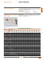
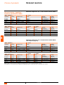
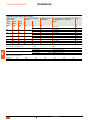
Varplus2 capacitors
installation guide
2006
Contents
Reactive power
Power definition
3
Electrical network pollution
Choice of compensation type
Choice of detuned reactor tuning frequency
4
6
2
Control and monitoring system
Physical and electrical control
Safety delay
7
9
3
1
Choice of products
Varplus2 capacitors
Detuned reactors
Varlogic power factor controllers
Contactors
10
14
17
19
Cubicle installation
Varplus2 capacitors
Detuned reactors
21
22
Ventilation system
Classic and comfort range
Harmony range
Derating for an ambient temperature 50 °C
23
24
25
Choice of protective devices
Circuit breakers – Fuses
26
7
Choice of cables
Power and auxiliary circuits
28
8
Customer installation recommendations
Current transformers and C/K
Varpact solution
29
31
9
28 avril 2006
1
4
5
6
1
2
28 avril 2006
Reactive power
Power definition
Network characteristics
Network voltage and frequency are the basic factors that determine the size
of an LV compensation cubicle. The reactive power Q varies according to
the squared voltage and the frequency.
Q = U2 x C x ω
C = capacitance
ω = 2 πf
f = network frequency
It is calculated:
b either from the electricity bills, to avoid paying for the reactive energy
b or from tan ϕ and a target tan ϕ’.
DB109689
Calculation of the reactive power
to be installed
where:
Q = reactive power
U = network voltage
Compensation schematic diagram:
Qc = Pa (tg ϕ - tg ϕ').
kvar installation calculation table
Before
Capacitor power in kvar to be installed per kW of load to increase the power factor (cos ϕ) or tan ϕ to
compensation a given value
tg ϕ
1.33
1.30
1.27
1.23
1.20
1.17
1.14
1.11
1.08
1.05
1.02
0.99
0.96
0.94
0.91
0.88
0.86
0.83
0.80
0.78
0.75
0.72
0.70
0.67
0.65
0.62
0.59
0.57
0.54
0.51
0.48
cos ϕ
0.60
0.61
0.62
0.63
0.64
0.65
0.66
0.67
0.68
0.69
0.70
0.71
0.72
0.73
0.74
0.75
0.76
0.77
0.78
0.79
0.80
0.81
0.82
0.83
0.84
0.85
0.86
0.87
0.88
0.89
0.90
tg ϕ
cos ϕ
0.75
0.80
0.584
0.549
0.515
0.483
0.450
0.419
0.388
0.358
0.329
0.299
0.270
0.242
0.213
0.186
0.159
0.132
0.105
0.079
0.053
0.026
0.59
0.86
0.733
0.699
0.665
0.633
0.601
0.569
0.538
0.508
0.478
0.449
0.420
0.392
0.364
0.336
0.309
0.282
0.255
0.229
0.202
0.176
0.150
0.124
0.098
0.072
0.046
0.020
0.48
0.90
0.849
0.815
0.781
0.749
0.716
0.685
0.654
0.624
0.595
0.565
0.536
0.508
0.479
0.452
0.425
0.398
0.371
0.345
0.319
0.292
0.266
0.240
0.214
0.188
0.162
0.136
0.109
0.083
0.054
0.028
0.46
0.91
0.878
0.843
0.809
0.777
0.744
0.713
0.682
0.652
0.623
0.593
0.564
0.536
0.507
0.480
0.453
0.426
0.399
0.373
0.347
0.320
0.294
0.268
0.242
0.216
0.190
0.164
0.140
0.114
0.085
0.059
0.031
0.43
0.92
0.905
0.870
0.836
0.804
0.771
0.740
0.709
0.679
0.650
0.620
0.591
0.563
0.534
0.507
0.480
0.453
0.426
0.400
0.374
0.347
0.321
0.295
0.269
0.243
0.217
0.191
0.167
0.141
0.112
0.086
0.058
0.40
0.93
0.939
0.904
0.870
0.838
0.805
0.774
0.743
0.713
0.684
0.654
0.625
0.597
0.568
0.541
0.514
0.487
0.460
0.434
0.408
0.381
0.355
0.329
0.303
0.277
0.251
0.225
0.198
0.172
0.143
0.117
0.089
0.36
0.94
0.971
0.936
0.902
0.870
0.837
0.806
0.775
0.745
0.716
0.686
0.657
0.629
0.600
0.573
0.546
0.519
0.492
0.466
0.440
0.413
0.387
0.361
0.335
0.309
0.283
0.257
0.230
0.204
0.175
0.149
0.121
0.33
0.95
1.005
0.970
0.936
0.904
0.871
0.840
0.809
0.779
0.750
0.720
0.691
0.663
0.634
0.607
0.580
0.553
0.526
0.500
0.474
0.447
0.421
0.395
0.369
0.343
0.317
0.291
0.264
0.238
0.209
0.183
0.155
28 avril 2006
0.29
0.96
1.043
1.008
0.974
0.942
0.909
0.878
0.847
0.817
0.788
0.758
0.729
0.701
0.672
0.645
0.618
0.591
0.564
0.538
0.512
0.485
0.459
0.433
0.407
0.381
0.355
0.329
0.301
0.275
0.246
0.230
0.192
0.25
0.97
1.083
1.048
1.014
0.982
0.949
0.918
0.887
0.857
0.828
0.798
0.769
0.741
0.712
0.685
0.658
0.631
0.604
0.578
0.552
0.525
0.499
0.473
0.447
0.421
0.395
0.369
0.343
0.317
0.288
0.262
0.234
0.20
0.98
1.131
1.096
1.062
1.030
0.997
0.966
0.935
0.905
0.876
0.840
0.811
0.783
0.754
0.727
0.700
0.673
0.652
0.620
0.594
0.567
0.541
0.515
0.489
0.463
0.437
0.417
0.390
0.364
0.335
0.309
0.281
0.14
0.99
1.192
1.157
1.123
1.091
1.058
1.007
0.996
0.966
0.937
0.907
0.878
0.850
0.821
0.794
0.767
0.740
0.713
0.687
0.661
0.634
0.608
0.582
0.556
0.530
0.504
0.478
0.450
0.424
0.395
0.369
0.341
0.08
1
1.334
1.299
1.265
1.233
1.200
1.169
1.138
1.108
1.079
1.049
1.020
0.992
0.963
0.936
0.909
0.882
0.855
0.829
0.803
0.776
0.750
0.724
0.698
0.672
0.645
0.620
0.593
0.567
0.538
0.512
0.484
3
1
Electrical network pollution Choice of compensation type
Devices using power electronics (variable speed drives,
rectifiers, UPS, arc furnaces, fluorescent lamps, etc.) circulate
harmonic currents in electrical networks. Such harmonics can
interfere with the operation of many devices. Capacitors are
highly sensitive to harmonics. A high level of harmonic
pollution causes capacitors to overheat and age prematurely
(breakdown).
Different types of compensation must be chosen according to
the power of the harmonic generators.
2
DB109690
Compensation solution can be of three types (classic, comfort, harmony),
depending on the level of network harmonic pollution.
It can be selected as follows:
b according to the Gh/Sn ratio
Example 1
U = 400 V
P = 450 kW
Sn = 800 kVA Gh = 50 kVA
Gh
-------- = 6,2 %
Classic range
Sn
V
DB109691
Sn: apparent power of the transformer.
Gh: apparent power of harmonics-generating receivers
(variable speed motors, static converters, power
electronics, etc.).
Qc: power of the compensation equipment.
U: network voltage.
Example 2
U = 400 V
P = 300 kW
Sn = 800 kVA Gh = 150 kVA
·
Gh
-------- = 18,75 %
Sn
V
Comfort range
Example 3
U = 400 V
Sn = 800 kVA
Gh
-------- = 50 %
Sn
Harmony range
P = 100 kW
Gh = 400 kVA
V
b according to the percentage of total harmonic current distortion THD(I)
measured.
(1) Beyond 50 %, a harmonic filtering study is required.
S
THD ( I ) × ------- < 5 %
Sn
V
Classic range
S
5 % < THD ( I ) × ------- < 10 %
Sn
V
Comfort range
S
10 % < THD ( I ) × ------- < 20 %
Sn
V
Harmony range
Sn = apparent power of the transformer.
S = load in kVA at the transformer secondary at the time of measurement.
Note: harmonics must be measured at the transformer secondary, at maximum load
and without capacitors.
The apparent power at the time of measurement must be taken into account.
4
28 avril 2006
Electrical network pollution Choice of compensation type
Customer needs
Below table describes typical solutions used in several types of activities.
Very frenquently
Usually
Occasionally
In any case, it is recommended to make measurements at site in order to
validate the final solution.
Classic
Comfort
Gh/Sn y 5 %
Pollution rate
Industry
Food and beverage
Textile
Wood
Paper
Printing
Chemical - pharmac
Plastic
Glass - Ceramic
Steel making
Metallurgy
Automotive
Cement
Mines
Reffinery
Micro-electronic
Tertiary
Banks - insurances
Supermarkets
Hospitals
Stadium
Amusement parks
Hotels - Offices
Energy & Infrastructures
Sub-station
Water distribution
Internet farm
Wind mills
Railways
Airports
Subway
Harbours
Tunnels
2
Harmony
15 % < Gh/Sn y 25 % 25 % < Gh/Sn y 50 %
28 avril 2006
5
Electrical network pollution Choice of detuned reactor tuning
frequency
General
DB109692
The detuned reactors (DR) are designed to avoid any amplification of the
harmonics present on the network and to protect the capacitors (it
corresponds to our Harmony range).
The detuned reactors generate an overvoltage at the
capacitor terminals. Capacitors of at least 480 V must be used
for a 400 V network.
2
Technical data
DB109693
Choice of tuning
The tuning frequency fr corresponds to the resonance frequency of
the L-C assembly.
1
fr = ------------------2π LC
We also speak of tuning order n.
For a 50 Hz network:
fr
n = ---------------50 Hz
DB109694
b the tuning frequency chosen must ensure that the harmonic current
spectrum range is outside the resonance frequency
b it is essential to ensure that no remote control frequencies are disturbed.
The most common tuning orders are 3.8 or 4.3 (2.7 is used for 3rd order
harmonics).
Curve: impedance module at point A
DR, 400 V, 50 Hz tuning frequency selection table
Harmonic generators (Gh)
Three-phase
Variable speed drives, rectifiers, UPS, starters
Remote control frequency (Ft)
Without
165 < Ft y 250 Hz 250 < Ft y 350 Hz Ft > 350 Hz
Tuning frequency
135 Hz
190 Hz
215 Hz
Tuning frequency
135 Hz
135 Hz (1)
-
190 Hz
-
215 Hz
-
Single-phase (Gh > 10 % Sn)
Discharge lamps, electronic ballast lamps, fluorescent
135 Hz
135 Hz
lamps, UPS, variable speed drives, welding machines
Single-phase Gh: power of single-phase harmonic generators in kVA.
(1) A tuning frequency of 215 Hz can be used in France with a remote control frequency of 175 Hz.
135 Hz
Concordance between tuning frequency, tuning order and relative
impedance (50 Hz network)
Tuning frequency (fr) Tuning order
Relative impedance
(n = fr/f)
(P = 1/n2) in %
135 Hz
190 Hz
215 Hz
6
2.7
3.8
4.3
28 avril 2006
13.7 %
6.92 %
5.4 %
Control and monitoring
system
Physical and electrical control
The Varlogic power factor controllers continually measure the reactive
power of the system and switch the capacitor steps ON and OFF to obtain
the required power factor. Their ten step combinations enable them to
control capacitors of different powers.
Step combinations
1.1.1.1.1.1
1.2.3.3.3.3
1.1.2.2.2.2
1.2.3.4.4.4
1.1.2.3.3.3
1.2.3.6.6.6
1.1.2.4.4.4
1.2.4.4.4.4
1.2.2.2.2.2
1.2.4.8.8.8
These combinations ensure accurate control, by reducing:
b the number of power factor correction modules
b labour.
Optimising the control in this way generates considerable financial benefits.
Explanations
Q1 = Power of the first step
Q2 = Power of the second step
Q3 = Power of the third step
Q4 = Power of the fourth step
etc.
Qn = Power of the nth step (maximum 12)
3
Examples
1.1.1.1.1.1 :
1.1.2.2.2.2 :
1.2.3.4.4.4 :
1.2.4.8.8.8 :
Q2 = Q1, Q3 = Q1, …, Qn = Q1
Q2 = Q1, Q3 = 2Q1, Q4 = 2Q1, …, Qn = 2Q1
Q2 =2Q1, Q3 = 3Q1, Q4= 4Q1, …, Qn = 4Q1
Q2 = 2Q1, Q3 = 4Q1, Q4= 8 Q1, …, Qn = 8 Q1
Calculating the number of electrical steps
The number of electrical steps (e.g. 13)
Depends on:
b the number of controller outputs used (e.g. 7)
b the chosen combination, according to the power of the various steps
(e.g. 1.2.2.2).
Number of electrical steps
Combinations Number of controller outputs used
1
2
3
4
5
6
7
8
9
10
11
12
1.1.1.1.1.1…
1.1.2.2.2.2…
1.2.2.2.2.2…
1.1.2.3.3.3…
1.2.3.3.3.3…
1.1.2.4.4.4…
1.2.3.4.4.4…
1.2.4.4.4.4…
1.2.3.6.6.6…
1.2.4.8.8.8…
9
16
17
22
24
28
30
31
42
55
10
18
19
25
27
32
34
35
48
63
11
20
21
28
30
36
38
39
54
71
12
22
23
31
33
40
42
43
60
79
1
1
1
1
1
1
1
1
1
1
2
2
3
2
3
2
3
3
3
3
3
4
5
4
6
4
6
7
6
7
4
6
7
7
9
8
10
11
12
15
5
8
9
10
12
12
14
15
18
23
28 avril 2006
6
10
11
13
15
16
18
19
24
31
7
12
13
16
18
20
22
23
30
39
8
14
15
19
21
24
26
27
36
47
7
Control and monitoring
system
Physical and electrical control
Example
150 kvar 400 V 50 Hz
Solution 1: physical control 10 x 15 kvar
15 + 15 + 15 + 15 + 15 + 15 + 15 + 15 + 15 + 15 ; sequence : 1.1.1.1.1.1
b 10 physical steps
b 10 contactors
b 12-step controller.
Labour, high cost: non-optimised solution.
Solution 2: electrical control 10 x 15 kvar
15 + 30 + 45 + 60 = 10 x 15 kvar electrical; sequence: 1.2.3.4
b 4 physical steps allowing for 10 different powers
b 4 contactors
b 6-step controller.
Optimisation of the compensation cubicle.
Possible powers (kvar)
3
Physical steps
15
30
15
b
30
45
b
60
b
75
(v)
90
b
105
b
135
150
b
(v) Other possible combinations.
b
b
b
b (v)
b
b
b
45
60
(v)
b
b
b
(v)
b
b
(v)
(v)
(v)
b (v)
b
b
Other solutions
10 x 15 kvar electrical
Sequence: 1.1.2.2.2 : 15 + 15 + 30 + 30 + 30 + 30 kvar.
Sequence: 1.1.2.3.3 : 15 + 15 + 30 + 45 + 45 kvar.
8
28 avril 2006
Control and monitoring
system
Safety delay
The Varplus capacitors have an internal discharge resistor that reduces the
voltage to 50 V in 1 minute after disconnection from the network.
It is essential that the discharge time be observed to prevent the capacitors
and contactors from ageing prematurely.
Automatic capacitor bank
The safety delay of the Varlogic controller must be set to a minimum of
60 seconds.
When the supply to the contactors is separate or different from the supply
to the controller, the control circuit must be wired to ensure that the
discharge time (60 s) of the capacitor is observed (for example the
contactors and the controller must be disconnected at the same time).
Fixed capacitor bank
In the case of manually controlled capacitors, there must be a system to
ensure that no capacitor can be connected more than once in less than
1 minute.
28 avril 2006
9
3
Varplus2 capacitors
Varplus2 modular capacitors allow by their
different assembly combination to cover many
power ratings (kvar) depending
on the voltage (V), frequency (Hz)
and harmonic pollution level of the network.
Classic range (Gh/Sn y 15 %)
PB100058
Choice of products
Varplus2 IP00.
Varplus2
400 V (kvar) 415 V (kvar)
Reference
5
5.5
51311
6.25
6.5
51313
7.5
7.75
51315
10
10.75
51317
12.5
13.5
51319
15
15.5
51321
20
21.5
51323
Assembly advised
25
27
2x
51319
30
31
2x
51321
40
43
2x
51323
50
53.5
2x
51321 + 51323
55
58.5
2x
51323 + 51321
60
64.5
3x
51323
65
3x
51323 + 51311
Maximum mechanical assembly: 4 capacitors and 65 kvar.
Assembly > 65 kvar: see conditions to respect in Varplus2 user manual.
DB109695
Technical data
4
DB109696
Example of Varplus2 IP00 assembly.
DB109697
Varplus2 accessories.
Weight of Varplus2 2.1 kg.
b capacitor rated voltage: 415 V, 3-phase 50 Hz
b HQ protection system built into each single phase element
v high current fault protection by HRC cartridge fuse
v low current fault protection by combination of single phase internal
overpressure device with the HRC fuse
b capacitance value tolerance: -5, +10 %
b insulation level:
v withstand 50 Hz 1 minute: 4 kV
v impulse wave withstand 1.2/50 µs: 15 kV
b voltage test: 2.15 Un (rated voltage) for 10 s
b maximum permissible overloads at service voltage network as per
IEC 60831 1/2:
v current: 30 % permanently
v voltage: 10 % (8 hours over 24 hours)
b with internaly fitted discharge resistors: residual voltage less than 50 V
in 1 minute
b total losses: less than 0.5 Watt/kvar (discharge resistors included)
b temperature class D (+55 °C):
v maximum: 55 °C
v average over 24 hours: 45 °C
v average over 1 year: 35 °C
v maximum: -25 °C
b colour:
v elements RAL 9005
v base and cover RAL 7030
b standards: IEC 60831 1/2, CSA 22-2 N°190, UL 810
b execution: indoor
b protection:
v IP00 without cover (option)
v IP20 or IP42 see accessories
b no earth connection is needed
b terminals: 3 M8 rods allowing 360° cable connection (without cover).
Accessories for Varplus2
Reference
1 set of 3-phase copper bars for connection and assembly of 2 and 51459
3 capacitors
1 set of protective cover (IP20) and cable glands (IP42) for 1, 2 and 51461
3 capacitors
Installation
All positions are convenient except vertical one with connecting terminals
upside down. Fixing holes for M6 screws.
A kit to replace Varplus by Varplus2 is available (ref. 51298).
10
19 mai 2006
Varplus2 capacitors
Varplus2 modular capacitors allow by their
different assembly combination to cover many
power ratings (kvar) depending
on the voltage (V), frequency (Hz)
and harmonic pollution level of the network.
Comfort range (15 % < Gh/Sn y 25 %)
PB100058
Choice of products
Varplus2 IP00.
Capacitors rated 480 V are necessary.
Varplus2
Usefull powers
Rated values
400 V (kvar) 415 V (kvar)
440 V (kvar) 480 V (kvar) Reference
5
5.5
6.1
7.2
51325
6.25
6.5
7.6
9
51327
7.5
8
8.8
10.4
51329
10
11
13
15.5
51331
12.5
13.5
14.3
17
51333
15
16.5
19.1
22.7
51335
Assembly advised
20
23
2x
51331
25
25
2x
51333
30
34
2x
51335
45
51
3x
51335
60
68
4x
51335
Maximum mechanical assembly: 4 capacitors and 62/68 kvar 400/415 V.
Assembly > 62 kvar: see conditions to respect in Varplus2 user manual.
DB109695
Technical data
DB109696
Example of Varplus2 IP00 assembly.
DB109697
Varplus2 accessories.
b capacitor rated voltage: 480 V, 3-phase 50 Hz
b HQ protection system built into each single phase element
v high current fault protection by HRC cartridge fuse
v low current fault protection by combination of single phase internal
overpressure device with the HRC fuse
b capacitance value tolerance: -5, +10 %
b insulation level:
v withstand 50 Hz 1 minute: 4 kV
v impulse wave withstand 1.2/50 µs: 15 kV
b voltage test: 2.15 Un (rated voltage) for 10 s
b maximum permissible overloads at service voltage network as per IEC
60831 1/2:
v current: 30 % permanently
v voltage: 10 % (8 hours over 24 hours)
b with internaly fitted discharge resistors: residual voltage less than 50 V
in 1 minute
b total losses: less than 0.5 Watt/kvar (discharge resistors included)
b temperature class D (+55 °C):
v maximum: 55 °C
v average over 24 hours: 45 °C
v average over 1 year: 35 °C
v minimum: -25 °C
b colour:
v elements RAL 9005
v base and cover RAL 7030
b standards: IEC 60831 1/2, CSA 22-2 No190, UL 810
b execution: indoor
b protection:
v IP00 without cover
v IP20 or IP42 see accessories
b no earth connection is needed
b terminals: 3 M8 rods allowing 360° cable connection (without cover).
Accessories for Varplus2
Weight of Varplus2 2.1 kg.
Reference
1 set of 3-phase copper bars for connection and assembly of 2 and 3 51459
capacitors
1 set of protective cover (IP20) and cable glands (IP42) for 1, 2 and 3 51461
capacitors
Installation
All positions are convenient except vertical one with connecting terminals
upside down. Fixing holes for M6 screws.
A kit to replace Varplus by Varplus2 is available (ref. 51298).
19 mai 2006
11
4
Varplus2 capacitors
Varplus2 modular capacitors allow by their
different assembly combination to cover many
power ratings (kvar) depending
on the voltage (V), frequency (Hz)
and harmonic pollution level of the network.
Comfort range (25 % < Gh/Sn y 50 %)
PB100058
Choice of products
Capacitors rated 480 V will be used with detuned reactor.
Varplus2
Usefull powers
tuning order
400 V (kvar) 415 V (kvar)
2.7
6.5
7
(135 Hz - 13.7 %)
12.5
13.5
Assembly advised
25
27
50
54
Rated values
440 V (kvar) 480 V (kvar) Ref
6.7
8
51337
13
15.5
51331
Usefull powers
tuning order
400 V (kvar) 415 V (kvar)
3.8 (190 Hz - 6.92 %) 6.5
7
or
7.75
8.25
4.3 (215 Hz - 5.4 %) 10
11
12.5
13.5
16.5
17.75
Assembly advised
25
27
30
31.25
Rated values
440 V (kvar) 480 V (kvar) Ref
7.6
9
51327
8.8
10.4
51329
11.8
14
51345
14.3
17
51333
19.1
22.7
51335
2 x 51331
2 x 51335 +
51333
Maximum mechanical assembly: 4 capacitors and 50/54 kvar 400/415 V.
Assembly > 50 kvar: see conditions to respect in Varplus2 user manual.
DB109695
Varplus2 IP00.
2 x 51333
51333 +
51335
3 x 51335
50
53.25
Maximum mechanical assembly: 4 capacitors and 65 kvar 400/415 V.
Assembly > 65 kvar: see conditions to respect in Varplus2 user manual.
4
DB109696
Example of Varplus2 IP00 assembly.
DB109697
Varplus2 accessories.
Weight of Varplus2 2.1 kg.
Technical data
b capacitor rated voltage: 480 V, 3-phase 50 Hz
b HQ protection system built into each single phase element
v high current fault protection by HRC cartridge fuse
v low current fault protection by combination of single phase internal
overpressure device with the HRC fuse
b capacitance value tolerance: -5, +10 %
b insulation level:
v withstand 50 Hz 1 minute: 4 kV
v impulse wave withstand 1.2/50 µs: 15 kV
b voltage test: 2.15 Un (rated voltage) for 10 s
b maximum permissible overloads at service voltage network as per IEC
60831 1/2:
v current: 30 % permanently
v voltage: 10 % (8 hours over 24 hours)
b with internaly fitted discharge resistors: residual voltage less than 50 V in
1 mn
b total losses: less than 0.5 Watt/kvar (discharge resistors included)
b temperature class D (+55 °C):
v maximum: 55 °C
v average over 24 hours: 45 °C
v average over 1 year: 35 °C
v minimum: -25 °C
b colour:
v elements RAL 9005
v base and cover RAL 7030
b standards: IEC 60831 1/2, CSA 22-2 No190, UL 810
b execution: indoor
b protection:
v IP00 without cover
v IP20 or IP42 see accessories
b no earth connection is needed
b terminals: 3 M8 rods allowing 360° cable connection (without cover).
Accessories for Varplus2
Ref.
1 set of 3-phase copper bars for connection and assembly of 2 and 3 capacitors51459
1 set of protective cover (IP20) and cable glands (IP42) for 1, 2 and 3 capacitors51461
Installation
All positions are convenient except vertical one with connecting terminals
upside down. Fixing holes for M6 screws. A kit to replace Varplus by
Varplus2 is available (ref. 51298).
12
19 mai 2006
Varplus2 capacitors
525 / 550 V - 50 Hz range for DR application,
400 / 415 V network.
Maximum ambient temperature: 50 °C
Maximum altitude: 1000 m
25% < Gh/Sn y 50% (see chapter 6 p 25)
Classic range (Gh/Sn y 15 %)
PB100058
Choice of products
DB109695
Varplus2 IP00.
Varplus2
Usefull powers 480 V (kvar) Rated values 525 V (kvar)
12.5
15
Usefull powers 525 V (kvar) Rated values 550 V (kvar)
Reference
51383
Reference
10.5
12.3
16.4
Assembly advised
21
24.6
32.8
49.2
59.7
51351
51353
51357
11.5
13.5
18
23
27
36
54
2 x 51351
2 x 51353
2 x 51357
3 x 51357
3 x 51357 + 51351
59
2 x 51351 + 51357
65.6
72
4 x 51357
Maximum mechanical assembly: 4 capacitors and 66/72 kvar 525/550 V.
Assembly > 66 kvar: see conditions to respect in Varplus2 user manual.
Polluted and highly polluted network (15 % < Gh/Sn y 50 %)
Capacitors rated 690 V will be used with detuned reactor 190/215 Hz,
135 Hz turning order on request.
Technical data
DB109696
Example of Varplus2 IP00 assembly.
DB109697
Varplus2 accessories.
Weight of Varplus2 2.1 kg.
b capacitor rated voltage: 550 V, 3-phase 50 Hz for slightly polluted network
b HQ protection system built into each single phase element
v high current fault protection by HRC cartridge fuse
v low current fault protection by combination of single phase internal
overpressure device with the HRC fuse
b capacitance value tolerance: -5, +10 %
b insulation level:
v withstand 50 Hz 1 minute: 4 kV
v impulse wave withstand 1.2/50 µs: 15 kV
b voltage test: 2.15 Un (rated voltage) for 10 s
b maximum permissible overloads at service voltage network as per IEC
60831 1/2:
v current: 30 % permanently
v en tension : 10 % (8 h sur 24 h)
v voltage: 10 % (8 hours over 24 hours)
b with internaly fitted discharge resistors: residual voltage less than 50 V
in 1 minute
b total losses: less than 0.5 Watt/kvar (discharge resistors included)
b temperature class D (+55 °C):
v maximum: 55 °C
v average over 24 hours: 45 °C
v average over 1 year: 35 °C
v minimum: -25 °C
b colour:
v elements RAL 9005
v base and cover RAL 7030
b standards: IEC 60831 1/2, CSA 22-2 N°190, UL 810
b execution: indoor
b protection:
v IP00 without cover
v IP20 or IP42 see accessories
b no earth connection is needed
b terminals: 3 M8 rods allowing 360° cable connection (without cover).
Accessories for Varplus2
1 set of 3-phase copper bars for connection and assembly of 2 and 3
capacitors
1 set of protective cover (IP20) and cable glands (IP42) for 1, 2 and 3
capacitors
Ref.
51459
51461
Installation
All positions are convenient except vertical one with connecting terminals
upside down. Fixing holes for M6 screws. A kit to replace Varplus by
Varplus2 is available (ref. 51298).
19 mai 2006
13
4
Choice of products
Characteristics
PB100059
The detuned reactors (DR) are designed to
protect the capacitors and prevent
amplification of the harmonics present on
the network.
Detuned reactors
Detuned reactor for 400 V - 50 Hz network
Tuning order: 4.3 (215 Hz)
Power restored by
the assembly reactorcapacitor
6.25 kvar/400 V - 50 Hz
12.5 kvar/400 V - 50 Hz
25 kvar/400 V - 50 Hz
50 kvar/400 V - 50 Hz
100 kvar/400 V - 50 Hz
I1 (A)
Power losses
(W)
Ref.
L (mH)
4.71
2.37
1.18
0.592
0.296
9
17.9
35.8
71.7
143.3
100
150
200
320
480
51573
52404
52405
52406
52407
I1 (A)
Power losses
(W)
Ref.
L (mH)
6.03
3
1.5
0.75
0.37
9.1
18.2
36.4
72.8
145.5
100
150
200
300
450
51568
52352
52353
52354
51569
I1 (A)
Power losses
(W)
Ref.
L (mH)
12.56
6.63
3.14
1.57
0.78
9.3
17.6
37.2
74.5
149
100
150
200
400
600
51563
51564
51565
51566
51567
Tuning order: 3.8 (190 Hz)
Power restored by
the assembly reactorcapacitor
6.25 kvar/400 V - 50 Hz
12.5 kvar/400 V - 50 Hz
25 kvar/400 V - 50 Hz
50 kvar/400 V - 50 Hz
100 kvar/400 V - 50 Hz
Tuning order: 2.7 (135 Hz)
4
Detuned reactor.
Power restored by
the assembly reactorcapacitor
6.25 kvar/400 V - 50 Hz
12.5 kvar/400 V - 50 Hz
25 kvar/400 V - 50 Hz
50 kvar/400 V - 50 Hz
100 kvar/400 V - 50 Hz
Characteristics
b
b
b
b
b
b
b
b
b
v
v
v
b
three-phase, dry, magnetic circuit, impregnated
cooling: natural
degree of protection: IP00
insulation class: H
standards: IEC 60289, EN 60289
rated voltage: 400/415 V three-phase 50 Hz
tuning order (relative impedance): 4.3 (5.4 %); 3.8 (6.9 %); 2.7 (13.7 %)
inductance tolerance per phase: - 5, +5 %
2
]
maximum constant current: Imp = [ ( 1, 1 ⋅ I 1 ) 2 + I 32 + I 52 + I72 + I 11
Imp = 1.31 . I1 for 4.3 tuning
Imp = 1.19 . I1 for 3.8 tuning
Imp = 1.12 . I1 for 2.7 tuning
harmonic current spectrum
As a % of the current of the
fundamental (I1)
Current I3
Current I5
Current I7
Current I11
b
b
b
b
b
14
Tuning
order 4.3
2%
69 %
19 %
6%
Tuning
order 3.8
3%
44 %
13 %
5%
Tuning
order 2.7
6%
17 %
6%
2%
insulation level: 1.1 kV
thermal withstand Isc: 25 x Ie, 2 x 0.5 second
dynamic withstand: 2.2 Isc (peak value)
dielectric test 50 Hz between windings and windings/earth: 3.3 kV, 1 min
thermal protection restored on terminal block 250 V AC, 2 A.
28 avril 2006
Choice of products
Detuned reactors
Operating conditions
DB109698
b
b
b
b
b
use: indoor
storage temperature -40 °C, +60 °C
relative humidity in operation: 20 to 80 %
saline mist withstand: 250 hours
operating temperature/altitude:
Altitude
(m)
1000
> 1000, y 2000
Minimum
Maximum
(°C)
0
0
(°C)
55
50
Highest average over any
period of:
1 year
24 hours
40
50
35
45
Detuned reactor.
Installation
b forced ventilation required (see chapter 6 page 24)
b vertical detuned reactor winding for better heat dissipation
b electrical connection:
v to a screw terminal block for 6.25 and 12.5 kvar detuned reactors
v to a drilled pad for 25, 50 and 100 kvar detuned reactors
b 470 V capacitors must be used with the detuned reactors in the case of
a 400/415 V, 50 Hz network
b as the detuned reactor is fitted with thermal protection, it is recommended
that the normally closed dry contact be used to disconnect the step in the
event of overheating.
Dimensions
Tuning order: 4.3 (215 Hz)
Power restored by the Fixing centre
detuned reactor/
distance
capacitor assembly
(mm)
6.25 kvar/400 V - 50 Hz 110 x 87
12.5 kvar/400 V - 50 Hz 205 x 110
25 kvar/400 V - 50 Hz
205 x 110
(1)
50 kvar/400 V - 50 Hz
100 kvar/400 V - 50 Hz 205 x 120
Maximum dimensions
(mm)
H
W
D
230
200
140
230
245
140
230
240
140
270
260
160
330
380
220
Weight
(kg)
8.6
12
18.5
25
42
Tuning order: 3.8 (190 Hz)
Power restored by the Fixing centre
detuned reactor/
distance
capacitor assembly
(mm)
6.25 kvar/400 V - 50 Hz 110 x 87
12.5 kvar/400 V - 50 Hz 205 x 110
25 kvar/400 V - 50 Hz
205 x 110
(1)
50 kvar/400 V - 50 Hz
100 kvar/400 V - 50 Hz 205 x 120
Maximum dimensions
(mm)
H
W
D
230
200
140
230
245
140
230
240
140
270
260
160
330
380
220
Weight
(kg)
8.5
10
18
27
42
Tuning order: 2.7 (135 Hz)
Power restored by the Fixing centre
detuned reactor/
distance
capacitor assembly
(mm)
6.25 kvar/400 V - 50 Hz 110 x 87
12.5 kvar/400 V - 50 Hz 205 x 110
25 kvar/400 V - 50 Hz
205 x 110
(1)
50 kvar/400 V - 50 Hz
100 kvar/400 V - 50 Hz 205 x 120
(1) 205 x 120 or 205 x 130 mm.
28 avril 2006
Maximum dimensions
(mm)
H
W
D
230
200
140
230
245
145
230
240
140
270
260
160
330
380
220
Weight
(kg)
9
13
22
32
57
15
4
Choice of products
Detuned reactors
Detuned reactor / capacitor /
contactor combination tables
Maximum temperature 40 °C and maximum altitude 2000 m
480 V capacitors
Qc 400 V
6.25 kvar
12.5 kvar
25 kvar
50 kvar
100 kvar
fr = 135 Hz
Qc 480 V
Capacitor ref.
DR ref.
8 kvar
15,5 kvar
31 kvar
62 kvar
124 kvar
51337 x 1
51331 x 1
51331 x 2
51335 x 2 + 51333
51335 x 4 + 51333 x 2
51563 x 1
51564 x 1
51565 x 1
51566 x 1
51567 x 1
480 V capacitors
Qc 400 V
6.25 kvar
12.5 kvar
25 kvar
50 kvar
100 kvar
fr = 215 Hz
fr = 190 Hz
Qc 480 V
Capacitor ref.
DR ref.
DR ref.
9 kvar
17 kvar
34 kvar
68 kvar
136 kvar
51327 x 1
51333 x 1
51333 x 2
51335 x 3
51335 x 6
51573 x 1
52404 x 1
52405 x 1
52406 x 1
52407 x 1
51568 x 1
52352 x 1
52353 x 1
52354 x 1
51569 x 1
4
Specific
contactors
LC1-DFK11M7 x 1
LC1-DFK11M7 x 1
LC1-DMK11M7 x 1
LC1-DWK12M7 x 1
-
Standard
contactors
LC1D12 x 1
LC1D25 x 1
LC1D38 x 1
LC1D95 x 1
LC1D115 x 1
Specific
contactors
LC1-DFK11M7 x 1
LC1-DFK11M7 x 1
LC1-DMK11M7 x 1
LC1-DWK12M7 x 1
-
Standard
contactors
LC1D12 x 1
LC1D25 x 1
LC1D38 x 1
LC1D95 x 1
LC1D115 x 1
Maximum temperature 50 °C and maximum altitude 1000 m
(see chapter 6 page 25)
550 V capacitors
Qc 400 V
6.25 kvar
12.5 kvar
25 kvar
50 kvar
100 kvar
fr = 135 Hz
Qc 550 V
Capacitor ref.
DR ref.
10,5 kvar
21 kvar
40,5 kvar
81 kvar
162 kvar
51363 x 1
51363 x 2
51353 x 3
3 x 51357 + 2 x 51353
9 x 51357
51563 x 1
51564 x 1
51565 x 1
51566 x 1
51567 x 1
550 V capacitors
Qc 400 V
6.25 kvar
12.5 kvar
25 kvar
50 kvar
100 kvar
fr = 215 Hz
fr = 190 Hz
Qc 550V
Capacitor ref.
DR ref.
DR ref.
11,5 kvar
23 kvar
46 kvar
90 kvar
180 kvar
51351 x 1
51351 x 2
1 x 51357 + 2 x 51353
5 x 51357
10 x 51357
51573 x 1
52404 x 1
52405 x 1
52406 x 1
52407 x 1
51568 x 1
52352 x 1
52353 x 1
52354 x 1
51569 x 1
Specific
contactors
LC1-DFK11M7 x 1
LC1-DGK11M7 x 1
LC1-DPK11M7 x 1
LC1-DWK12M7 x 1
Standard
contactors
LC1D12 x 1
LC1D25 x 1
LC1D40 x 1
LC1D95 x 1
LC1F185 x 1
Specific
contactors
LC1-DFK11M7 x 1
LC1-DGK11M7 x 1
LC1-DPK11M7 x 1
LC1-DWK12M7 x 1
Standard
contactors
LC1D12 x 1
LC1D25 x 1
LC1D40 x 1
LC1D95 x 1
LC1F185 x 1
Note: LC1D contactors not incorporating a preinstalled resistor can be used with detuned reactors.
The inductance of the detuned reactor limits the energising current to a value that can be accepted by the contactor.
16
28 avril 2006
Choice of products
PB100056
The Varlogic N controllers permanently
measure the reactive power of the
installation and control connection and
disconnection of capacitor steps in order to
obtain the required power factor.
PB100057
Varlogic NR6/NR12
DB109699
Varlogic NRC12
Varlogic power factor controllers
Technical data
b general data
v Modbus communication option NRC12
v operating temperature: 0…60 °C
v storage temperature: -20° C…60 °C
v colour: RAL 7016
v standard:
- EMC: IEC 61326
- electrical: IEC/EN 61010-1.
v panel mounting
v mounting on 35 mm DIN rail (EN 50022)
v protection class in panel mounting:
- front face: IP41
- rear face: IP20.
- display:
- NR6, NR12 type: backlighted screen 65 x 21 mm
- NRC12 type: backlighted graphic screen 55 x 28 mm.
- languages: English, French, German, Portuguese, Spanish
v alarm contact
v temperature internal probe
v separate contact to control fan inside the power factor correction bank
v access to the history of alarm.
b inputs
v phase to phase or phase to neutral connection
v insensitive to CT polarity
v insensitive to phase rotation polarity
v current input:
- NR6, NR12 type: CT… X/5 A
- NRC12 type: CT… X/5 A et X/1 A.
b outputs
v potential free output contacts:
- AC : 1 A/400 V, 2 A/250 V, 5 A/120 V
- DC : 0,3 A/110 V, 0,6 A/60 V, 2 A/24 V.
b settings and parameters
v target cos ϕ setting: 0,85 ind…0,9 cap
v possibility of a dual cos ϕ target (type NRC12)
v manual or automatic parameter setting of the power factor controller
v choice of different stepping programs:
- linear
- normal
- circular
- optimal.
v main step sequences:
1.1.1.1.1.1
1.2.3.3.3.3
1.2.2.2.2.2
1.2.4.4.4.4
1.2.3.4.4.4
1.1.2.3.3.3
1.1.2.2.2.2
1.2.4.8.8.8
v personalized sequences for NRC12 type
v delay between 2 successive switch on of a same step:
- NR6, NR12 type: 10 … 600 s
- NRC12 type: 10 … 900 s
v step configuration programming (fixed/auto/disconnected) (NRC12 type)
v 4 quadrant operation for generator application (NRC12 type)
manuel control for operating test.
Dimensions
Varlogic N
Varlogic NR6, NR12, NRC12
Varlogic NR6/NR12
Varlogic NRC12
Dimensions (mm)
H
L
D1
D2
Weight
(kg)
150
150
70
80
60
70
1
1
150
150
28 avril 2006
17
4
Choice of products
Type
Varlogic power factor controllers
Number of step
output contacts
Supply voltage (V)
network 50-60 Hz
Measuring
voltage (V)
ref.
NR6
6
110-220/240-380/415
110-220/240-380/415
NR12
12
110-220/240-380/415
110-220/240-380/415
NRC12
12
110-220/240-380/415
110-220/240-380/415-690
52448
52449
52450
ref.
52451
52452
Varlogic N accessories
Communication RS485 Modbus set for NRC12
Temperature external probe for NRC12 type. In addition to internal proble, allows measurement at the hotest point inside the capacitor bank.
Better tuning of alarm and/or disconnection level.
Information supplied
Cos ϕ
Connected steps
Switching cycles and connected time counter
Step configuration (fixed step, auto, disconnected)
Step output status (capacitance loss monitoring)
Network technical data: load and reactive currents, voltage, powers (S, P, Q)
Ambient temperature inside the cubicle
Total voltage harmonic distortion THD (U)
Total current harmonic distortion THD (I)
Capacitor current overload Irms/I 1
Voltage and current harmonic spectrum (orders 3, 5, 7, 11, 13)
History of alarms
Alarms
Low power factor
Hunting (unstable regulation)
Abnormal cos ϕ
Overcompensation
Overcurrent
Voltage low
Overvoltage
Overtemperature
4
Threshold
< 0.5 ind or 0.8 cap
NRC12
b
b
b
b
b
b
b
b
b
b
b
b
b
b
b
b
Action
NR6/NR12
NRC12
message and alarm contact
message and alarm contact
message and alarm contact
message and alarm contact
message and alarm contact
message and alarm contact
message and alarm contact
message and alarm contact
fan switch
message and alarm contact
message and alarm contact
message and alarm contact
message
message
message
b
b
b
b
b
b
b
b
b
b
b
b
b
b
b
b
b
b
b
b
b
b
b
b
b
disconnection (2)
disconnection
disconnection
disconnection
disconnection
disconnection
disconnection
disconnection
(2)
(2)
(2)
(2)
(2)
(2)
(2)
b
b
DB109700
> 115 % I1
< 80 % Uo within 1 s
> 110 % Uo
θ u θo (θo = 50 °C max)(1)
θ u θo - 15 °C
Total harmonic distortion
> 7 % (1)
Capacitor current overload (Irms/I 1) > 1.5 (1)
Capacitor capacitance loss
- 25 %
Low current
< 2,5 %
High current
> 115 %
Under voltage
5 % Uo
Uo: input voltage (measurement)
(1): alarm threshold values can be modified according to the installation
(2): capacitor steps are automatically reconnected after fault clearance and a safety delay
18
NR6/NR12
b
b
b
28 avril 2006
Choice of products
Contactors
DB109701
General
Capacitor control is accompanied by transient operating conditions
resulting from the capacitor load which, amongst other things, generates a
very high overcurrent equivalent to a short-circuit of short duration.
The use of standard contactors may compromise the safety of persons and
installations.
Telemecanique contactors for capacitor control
The LC1-D•K contactors are specially designed for capacitor control.
They are fitted with a contact block allowing the current to pass on closing
and with damping resistors limiting the current on energisation.
This technology, which is unique, has been patented.
DB109702
Personal safety
The contactors cannot be operated manually.
The contactors are fitted with covers for protection against direct contact.
Safety of installations
The damping resistors are disconnected after the capacitor current
energising peak. A faulty contactor pole therefore does not allow the
permanent current to flow through the resistor and prevents it from burning.
Simplicity and durability
LC1-D•K contactors are a ready-to-use solution that does not require the
installation of shock coils.
Their durability is far greater than that of conventional solutions
(300,000 operating cycles at 400 V).
Note: if specific contactors cannot be used to control the capacitors, then energising
current limiting reactors must be used. Please consult the contactor manufacturer.
Note: LC1D contactors not incorporating a preinstalled resistor can be used with
detuned reactors.
The inductance of the detuned reactor limits the energising current to a value that
can be accepted by the contactor.
28 avril 2006
19
4
Contactors
Choice of products
References and maximum power ratings (1)
Power ratings
temp. y 55 °C
220 V
400 V
240 V
440 V
Instantaneous auxiliary
contacts
Tightening torque
on end-piece
Nm
1.2
1.2
1.7
1.7
1.9
1.9
2.5
2.5
5
5
9
660 V
690 V
kvar
6.5
kvar
12.5
kvar
18
"F"
1
6.5
15
24
1
10
20
30
1
15
25
36
1
20
25
40
30
40
60
48
58
92
1
1
1
"O"
1
2
1
2
1
2
1
2
2
2
2
Basic reference no. to which the control Weight
voltage reference no. should be
added (2)
kg
LC1-DFK11••
LC1-DFK02••
LC1-DGK11••
LC1-DGK02••
LC1-DLK11••
LC1-DLK02••
LC1-DMK11••
LC1-DMK02••
LC1-DPK12••
LC1-DTK12••
LC1-DWK12••
0.43
0.43
0.45
0.45
0.6
0.6
0.63
0.63
1.3
1.3
1.65
(1) The power values in the above table are valid for the following conditions:
Prospective peak energising current
LC1-D•K
Maximum rate
LC1-DKF/DKG/DLK/DMK/DPK
240 operating cycles/hour
LC1-DTK/DWK
100 operating cycles/hour
Electrical durability at nominal load
4
200 In
LC1-DKF/DKG/DLK/DMK/DPK
400 V
300000 operating cycles
LC1-DTK/DWK
690 V
300000 operating cycles
(2) Control circuit voltage (••) :
Tension (V)
110
220
230
240
380
400
415
50/60 Hz
F7
M7
P7
U7
Q7
V7
N7
Other voltages: contact us.
20
28 avril 2006
Varplus2 capacitors
Cubicle installation
Fixing and installation
DB109717
b the capacitors must be installed in well ventilated rooms or enclosures to
ensure that they do not exceed the temperature category limits (see chapter
4, page 10 and chapter 6)
b whatever the installation conditions, the capacitors can be installed in any
position but upside down, like you can see on the drawings.
b capacitors mounted one above the other inside an enclosure should be
at least 25 mm apart
b for a lightning withstand of 25 kV, there should be at least 15 mm between
the rear panel and any metal part.
DB109716
Right.
Assembly until 130 kvar
There are 3 conditions to respect:
b adapted bus bar section is expected to connect the capacitor assemblies
shown below
b minimum space of 25 mm is expected between 2 groups of capacitors
(see following figure)
b according to "Ventilation" chapter, specific precautions must be taken in
order to not exceed temperature category of -25 °C/D inside the cubicle.
DB109719
DB109688
Right.
5
DB109687
Right.
DB109703
Wrong.
28 avril 2006
21
Cubicle installation
Detuned reactors
Temperature rise stresses
DB109704
The detuned reactors should be mounted in the upper part of the cubicle to
avoid overheating the installed switchgear.
In the case of a correction switchboard with detuned reactors, a separate
column should be specifically reserved for the reactors.
Detuned reactors require forced ventilation (see page 24).
Note: under no circumstances may the detuned reactors be fitted beneath the
capacitors.
Example of capacitor banks with detuned reactors
(DRs).
5
Location of the detuned reactors
DB109705
To ensure proper ventilation, the DR windings must be vertical.
Installation distance
DB109706
The minimum distances illustrated opposite must be observed for insulation
purposes and to prevent overheating.
22
28 avril 2006
Ventilation system
The ventilation rules given in this manual
are valid under normal operating conditions.
They ensure that the temperatures within
the cubicles do not exceed the maximum
temperatures to which the components can
be subjected.
The rules provide for an average delta T of
10 to 15 °C between the outside and inside
of the cubicle.
Classic and comfort range
Normal operating conditions to IEC 60439-1
b
b
b
b
b
maximum temperature in the electrical room: 40 °C
average temperature over 24 hours in the electrical room: 35 °C
average annual temperature in the electrical room: 25 °C
minimum temperature: -5 °C
maximum altitude: 2000 m.
The following rules apply to Varplus2 capacitors for
classic and comfort solutions.
DB109707
Ventilation rules
Capacitors, contactors, fuses and electrical connections dissipate heat:
2.5 W/kvar.
The following ventilation rules must therefore be complied with:
b the air within the cubicle must flow upwards.
It is recommended that extractor fans be fitted on top of the cubicle.
b the cross-section of the top air outlet must be at least 1.1 times the crosssection of the bottom air outlet
b the openings must be compatible with the safety rating (IP)
b there should be at least 100 mm between the fan and the modules or
components
b the air inlet at the bottom air intake grille must not be obstructed or
restricted by a component or module.
Applications
The ventilation rules apply to cubicles with the following dimensions:
b height H = 2000 mm
b width W = 600 mm minimum
b depth D = 400 mm minimum
b and power less than or equal to 405 kvar 400 V - 50 Hz per column.
Reactive power
(kvar at 400 V - 50 Hz)
Type of
ventilation
Air inlet
Min. air flow
(m3/hour)
Cubicle safety rating (IP) y 3X
Power y 100 kvar
Natural
Power 100 to 200 kvar
Natural
Power > 200 kvar
Forced
200 cm2
400 cm2
-
u 0.75 times the
power in kvar
Cubicle safety rating (IP) > 3X
All power values
Forced
-
u 0.75 times the
power in kvar
28 avril 2006
23
6
Ventilation system
Harmony range
Design using Varplus2 capacitors
and detuned reactors (DR)
Normal operating conditions to IEC 60439-1
The ventilation rules given in this manual
are valid under normal operating conditions.
They ensure that the temperatures within
the cubicles do not exceed the maximum
temperatures to which the components can
be subjected.
The rules provide for an average delta T of
10 to 15 °C between the outside and inside
of the cubicle.
b
b
b
b
b
maximum temperature in the electrical room: 40 °C
average temperature over 24 hours in the electrical room: 35 °C
average annual temperature in the electrical room: 25 °C
minimum temperature: -5 °C
maximum altitude: 2000 m.
The following rules apply to Varplus2 capacitors
associated with detuned reactors (Harmony range).
Ventilation for capacitor banks with detuned reactors
DB109707
This equipment must always include a forced ventilation system.
The DRs must be installed:
b in a separate enclosure
b or in the same enclosure as the capacitors, but in a separate
compartment, or possibly above the capacitors.
The part of the enclosure containing the capacitors must be ventilated
according to the standard capacitor bank rules, see page 23.
The part of the enclosure containing the DRs must be ventilated according
to the dissipated power.
The minimum air flow must be: F = 0.3 x Ps
(Ps = power dissipated by the DRs).
Example
250 kvar 400 V DR capacitor bank, tuning 190 Hz,
in 1 x 50 kvar + 2 x 100 kvar:
b DR compartment: forced ventilation
Ps = 300 + 2 x 450 = 1200 W
F = 0.3 x Ps = 0.3 x 1200 = 400 m3/h
b capacitor compartment: forced ventilation
(cubicle: 600 x 400 x 2000)
fan rate: 0.75 x 250 = 187.5 m3/h.
6
24
28 avril 2006
Ventilation system
Derating for an ambient
temperature 50 °C
Compensation installation can be provided for the following operating
conditions:
b maximum temperature in the electrical room: 50 °C
b average temperature over 24 hours in the electrical room: 45 °C
b average annual temperature in the electrical room: 35 °C
b minimum temperature: -5 °C
b maximum altitude: 1000 m.
The following precautions must be taken:
bventilation must be forced, irrespective of the power, and the ventilation
rate increased by 25 % (see the rules on pages 23 and 24):
v classic and comfort installation consisting of modules or capacitors:
rate (m3/h) = 0.75 x Q (kvar) x 1.25, whatever the power of Q
v harmony installation consisting of components (capacitors + DR):
- capacitor compartment rate: see rule point 1
- DR compartment rate: (m3/h): 0.3 x Ps x 1.25
b the capacitor voltage must be higher than that normally required
(minimum 10 % higher than that specified by the normal dimensioning
rules)
b the DR temperature sensor must be connected so that the step can be
disconnected if the temperature is too high
b the contactors must be derated, the operating current must be increased
by 10 % with respect to the maximum constant current of the step.
Example: 30 kvar 400 V step, classic range, rated current = 43.3 A:
Imp = 1.36 x 43.3 = 58.9 A.
At a maximum ambient temperature of 50 °C, the contactor must be able to
accept a current of 58.9 x 1.1 = 65 A
b the cables must be appropriate for a current of at least 1.5 times the rated
current of the capacitor at a minimum temperature of 60 °C.
Summary
400/415 V 50 Hz network
Gh/Sn y at 15 %
Comfort capacitors (480 V)
15 % < Gh/Sn y 25 % 25 % < Gh/Sn y 50 %
550 V capacitors
550 V capacitors
+ DR from the catalogue
6
28 avril 2006
25
Circuit breakers – Fuses
Capacitor bank protection
by means of a circuit breaker
Their rating must be chosen to allow the thermal protection to be set to:
b 1.36 In for classic range
b 1.5 In for comfort range
b 1.12 In for harmony range: 2.7 tuning
b 1.19 In for harmony range: 3.8 tuning
b 1.31 In for harmony range: 4.3 tuning
DB109708
Choice of protective
devices
The short-circuit (magnetic) protection setting thresholds must allow the
energising transients to pass through:
10 x ln for classic, comfort and harmony ranges.
In= Qc/ (1.732 x Un)
Example 1
150 kvar / 400 V - 50 Hz - classic range
150000
In = -------------------- = 216 A
400 3
Thermal protection: 1.36 x 216 = 294 A
Magnetic protection > 10 In = 2160 A.
Example 2
150 kvar / 400 V - 50 Hz - harmony range (4.3 tuning)
In = 216 A
Thermal protection: 1.31 x 216 = 283 A
Magnetic protection > 10 In = 2160 A.
Capacitor bank protection
by means of fuses
Type Gg HBC fuses must be used with the following ratings:
b classic range: 1.4 In
b comfort range: 1.6 In
b harmony range: 1.4 In.
DB109709
Example 1
150 kvar / 400 V - 50 Hz – comfort range
In = 216 A
Fuse rating u 1,6 x 216 u 346 A
Exemple 2
150 kvar / 400 V - 50 Hz - harmony range
In = 216 A
Fuse rating u 1,4 x 216 u 302 A
The fuse rating immediately above the calculated value must be used.
7
26
28 avril 2006
Choice of protective
devices
Circuit breakers – Fuses
Step protection by means of fuses
Type Gg HBC fuses must be used with the following ratings:
b classic and comfort ranges: 1.6 In
b harmony range: 1.5 In.
DB109710
Note: when 2 steps are protected by the same set of fuses, the coefficients are:
b 1.4 In for classic and harmony steps
b 1.6 In for comfort steps.
Protection of the transformer
supplying the auxiliaries
Use of a transformer to supply the auxiliaries
The transformer must be sufficiently powerful to supply the contactor coils
(drive and holding), the controllers and other energy-consuming devices
(fans, lamps, etc.).
Table showing the choice of protective devices at the
transformer primary for transformers with an inrush current of
25 In (primary voltage 400 V)
Power
VA
63
100
160
250
400
630
800
1000
Primary In
A
aM fuse
A
Circuit breaker
Curve B
0.16
0.25
0.4
0.62
1
1.57
2
2.5
1
1
1
2
4
4
4
6
1
1
1
2
2
3
4
6
Table showing the choice of protective devices at the
transformer secondary (secondary voltage 230 V single-phase)
Power
VA
Secondary In
A
63
0.27
100
0.43
160
0.70
250
1.09
400
1.74
630
2.74
800
3.49
1000
4.35
(1) No overload protection provided.
28 avril 2006
gG fuse
A
Circuit breaker
Curve C
0.5 (1)
0.5
1
1
2
4
4
4
0.5 (1)
0.5
0.75
1
2
3
4
4
7
27
Choice of cables
Power and auxiliary circuits
Step power cables
Flexible, rigid or semi-rigid copper cables are generally used inside the
switchboard.
A U 1000 V cable (insulation 1000 V) is recommended.
For a working voltage that is less than half the insulation voltage of the
cable, i.e. < 500 V, these cables are considered to be class 2.
They can therefore be flanged directly onto metal supports without the use
of an insulating material.
The cable cross-section must be compatible with:
b the current to be carried
b the ambient temperature around the conductors.
Dimensioning rules:
b the ambient temperature in the electrical room must not exceed 40 °C:
the cables must be appropriate for a current of at least 1.5 times the
capacitor current at a temperature of 50 °C
b the ambient temperature in the electrical room must not exceed 50 °C:
the cables must be appropriate for at least 1.5 In at a temperature of 60 °C.
Auxiliary circuits
Unless otherwise stated in the specifications, the following cable crosssections are recommended for the auxiliary wiring:
b 1.5 mm2 for the auxiliary voltage circuits
b 2.5 mm2 for the auxiliary current circuits.
Capacitor bank connection cables
Dimensioning current
The cables must be appropriate for a current of at least 1.5 In.
Cross-section
It must be compatible with:
b the ambient temperature around the conductor
b the method of installation (trunking, duct, etc.).
See the cable manufacturer's recommendations.
Recommended cable cross-sections (U1000 R02V cables)
For capacitor connections at an ambient temperature of 35 °C.
Power (kvar)
230 V
15
20
25
30
40
50
60
80
90
100
120
135
165
180
200
240
8
28
400 V
Cross-section (mm2)
Cu
Al
25
30
45
60
75
90
110
135
150
180
200
240
275
300
360
400
6
10
16
25
35
50
70
95
120
2 x 50
2 x 70
2 x 70
2 x 95
2 x 120
2 x 150
2 x 185
28 avril 2006
16
16
25
35
50
70
95
2 x 50
2 x 70
2 x 70
2 x 95
2 x 150
2 x 150
2 x 185
2 x 240
2 x 300
Current transformers and C/K
Customer installation
recommendations
Installation recommendations
DB109711
b the CT current transformer must be installed upstream of the installation
to be compensated
b the controller voltage should be set between L2 and L3 and the CT to
phase L1
b the capacitor bank wiring diagram should be designed to ensure that the
time required to discharge the capacitors is observed (minimum 1 minute),
for example in the event of a loss of contactor auxiliary voltage
b if the installation comprises two or more supply transformers, a summing
CT that will take all the energy consumed by the installation into account
must be provided. The ratio to be used to calculate the C/K is the sum of
the ratios of the various measuring CTs
b if the installation includes a generator set, a contact will disconnect the
capacitor bank in the event of generator set operation.
The best method is to use it to cut off the supply to the controller.
DB109713
DB109712
Measuring current on phase L3
DB109715
Connecting two transformers in parallel
9
28 avril 2006
29
Customer installation
recommendations
Current transformers and C/K
Calculation of the response current C/K for power factor
controllers
All the Ct.A, Ct.B, Ct.C and Ct.D current transformers must have
the same ratio (same primary and secondary 5 A).
C = current of the first capacitor bank step.
K = current transformer ratio.
Assumptions
b transformer 1 = transformer 2 = 1600 kVA
b network: 400 V 50 Hz
b capacitor bank A = 300 kvar 400 V, 5 x 60 kvar
b capacitor bank B = 250 kvar 400 V, 5 x 50 kvar
Calculation of the current transformer ratio
Transformer rated current: 160000/400/1.732 = 2310 A.
The transformer primary current must therefore be greater than 2310 A.
A transformer with a primary current of 2500 A should therefore be used.
The transformer secondary current must be 5 A.
We therefore obtain: Ct.A = Ct.B = Ct.C = Ct.D = 2500/5 A.
Choice of summing current transformers
Ct.E = Ct.F = (5 + 5)/5 A.
Calculation of C/K for capacitor bank A
Ca = first step current = 60000/400/1.732 = 86.6 A.
Ka = (Ct.A primary + Ct.C)/5 = 1000.
Ca/Ka= 86.6/1000 = 0.086.
Calculation of C/K for capacitor bank B
Cb = first step current = 50000/400/1.732 = 72 A.
Kb = (Ct.B primary + Ct.D primary)/5 = 1000.
Cb/Kb = 72/1000 = 0.072.
9
30
28 avril 2006
Customer installation
recommendations
Varpact solution
PB100061
Save time, Save money!
Schneider Electric can offer you a simple prewired solution : the Varpact
power correction modules.
It allows you to do your cubicle installation much quicker and easier.
The Varpact modules form a prewired subassembly designed for fittings in
power factor correction cubicles.
There are single modules (with one contactor) and double modules (with 2
contactors).
Varpact classic without bus bars
It covers all the need you can have, depending of the pollution rate on the
network (see chapter 2 p 4):
b Varpact classic
b Varpact comfort
b Varpact harmony
PB100062
As you can see on the pictures besides, all the modules can be assembled
with or without busbars, depending of your choice.
Varpact modules benefits
Varpact means " simplicity ":
b complete range according to network pollution level
b easy installation in all cubicles type
Varpact means " peace of mind ":
b fully tested before dispatch
b includes protection against direct contacts
PB100063
Varpact classic with bus bars
PB100064
Varpact harmony without bus bars
9
Varpact harmony with bus bars
28 avril 2006
31
Notes
32
28 avril 2006
Rectiphase
399, rue de la Gare
74370 Pringy
France
Tél : +33 (0)4 50 66 95 00
Fax : +33 (0)4 50 27 24 19
http://www.schneider-electric.com
http://www.merlin-gerin.com
http://www.schneider-electric.co
ART816860
CFIED206099EN
As standards, specifications and design change from time to time, always ask for confirmation
of the information given in this publication.
Printed on recycled paper.
Création, published by: Schneider Electric - Ameg
Photos : Schneider Electric
Printed by:
04-2006
© 2006 - Schneider Electric - All rights reserved
Schneider Electric Industries SAS