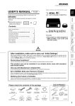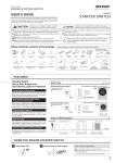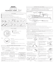
1
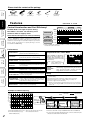
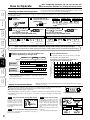
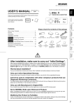
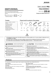
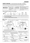
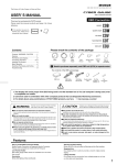
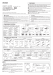
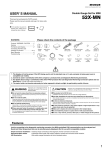
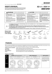
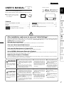
(THC As of June, 2015 No.16)
USER’S MANUAL (
Product Number :
THC
)
Throttle Controller
THROTTLE CONTROLLER
Please read this manual carefully and keep it for future reference.
Product
+
Features
●If this product is given to another
user, make sure to include this
User’ s Manual.
Connecting The Wires ……………………… 3 〜4
procedure 2
Installing The Product / Part Names …………… 4
Initial Settings (Degree of Acceleration Setting) …… 5
Installing
The Product
procedure 1
procedure 3
How to Operate……………………………………………… 6〜7
Troubleshooting ………………………………………………… 7
Overview of Change Characteristics…………………………… 8
Connecting
The Wires
Contents
Before Using / WARNING / CAUTION …………………………1
Contents ………………………………………………………… 2
Features……………………………………………………………2
Before
Using
3 drive・COMPACT
Thank you for purchasing PIVOT product.
After having installed this product, make sure to make settings for your car’ s special characteristics by carrying out the “Initial
Settings” on Page 5. If the “Initial Settings” are not carried out, a Check Engine Light may go on. Also, the unit will remain in
NORMAL Mode even if the Mode is switched.
How to
Operate
Worried about Installation?
Initial
Settings
After installation, make sure to carry out “Initial Settings”.
If you are worried about carrying out wiring or other installation procedures please consult your dealer.
Only use 3-drive Specialized Harness.
Using another type of harness will cause troubles and failure; use only the 3-drive specialized harness.
Only use with Manufacturer’s Original ECU.
Set to NORMAL Mode upon Removal of Product.
nor
When uninstalling the product, make sure to return it to
(NORMAL) Mode before carrying out any work. Reconnecting this product in
a different mode may cause the Check Engine Light to come on.
TroubleShooting
Do not install this product if the ECU is not the original one or when a sub-ECU is being used.
Modifying this Product is Forbidden.
WARNING
Improper use or disregard
of these war nings may
result in the injury or death
of people.
CAUTION
Improper use or disregard
of these war nings may
cause injury to persons,
damage the product and/or
other things.
●When making initial settings make sure
to stop the engine and place in Parking
or Neutral. It is dangerous to carry out
these settings while the engine is
running.
●Do not work in areas where there is
ex c e s s i ve ex h a u s t . D u e t o ve h i c l e
exhaust emission poisoning or fire may
result in a damage to humans.
●Do not crush the cable. Please be
careful that the cable does not
get crushed by the seat rail or car
door steel plate, nor cut by any
shar p steel plate as this may
cause a poor connection or an
electric short leading to fire or
other danger.
●While driving DO NOT operate
switches or pay prolonged
attention to the display; it is
extremely dangerous.
●Make sure that all wiring and
fastening down of the product
does not interfere with driving
nor be done in such a way as
to cause poor connections.
● P I VOT C o r p o ra t i o n a c c e p t s n o
responsibility, in any manner whatsoever,
for damage and/or trouble to your vehicle
or product, nor for any accidents that are
the result of the misuse of this product.
●Please confirm that the type of vehicle
you wish to install into is listed in the “List
of Specialized Harnesses by Car Model
for 3-drive · COMPACT” .
●When installing this product, we
recommend that if technical knowledge
becomes necessary please consult a
qualified mechanic.
●If the device is improper ly
installed or settings have been
improperly made a Check Engine
Light may go on.
●Do not use electrotap.
●Wir ing should be carr ied out
using the attached “cut connector” or by soldering, make sure to
securely insulate all wiring parts
with insulation tape, and confirm
that no wires are sticking out.
●Please wipe with a soft dr y
cloth (a lens cloth).
●Please do not use alcohol or
benzine.
This may cause damage to the
painted surface or cracks in
the plastic.
● D o n o t , i n a n y m a n n e r,
process, take apart, or make
changes to this product.
Control
Features
Under no circumstances should modifications or changes be made to this product. Doing so may cause damage not only to the product,
but to the car and the operation of the car in which it is installed.
1
Black
Extension
Cord
Main Unit
[60×22×55 (D) mm]
Double-sided
Tapes
[25×35mm] ×2
Cut
Connectors
×4
Zip tie
×2
User’s Manual
(This Book)
Features
Features
Before
Using
Please check the contents of the package
SPORTS & ECO
TroubleShooting
Control
Features
Select the kind of response to match your driving.
3-drive・COMPACT enables changing the response for
electronic throttle car models and gives you, the driver, the
freedom to select the type of acceleration response you need or
desire: quick acceleration for speedy dr iving to slower
acceleration for ECO-driving. SPORTS
MODE
7
6
NORMAL
5
4
3
2
1
1
ECO
2
3
4
5
Good
RESPONSE
Bad
Good
FUEL
EFFICIENCY
ROAD GRIP
Bad
Slippery
(during acceleration)
No slip
※ Even in ECO Mode, if rapid acceleration is carried out over and over again
fuel efficiency will not increase.
Performance
SPORTS MODE
High response for sporty situations.
(ideal for circuit, mountain driving, etc...)
ECO MODE
Low response for Eco-driving situations.
(perfect for city and fuel conscious driving)
NORMAL MODE
Standard Performance.
ACCELERATION
MONITOR
Displays the amount of pressure on the accelerator and helps to prevent poor fuel efficiency due to
over acceleration.
3 MODES
12 STEPS
One-touch selection between 3 modes and 12 steps.
(SPORTS Mode = 7 steps, ECO Mode = 5 steps)
Improved Results in ECO Mode
3-drive・COMPACT in ECO Mode
reduces the output signal at full
throttle to 80% of that when using
a standard unit, hence increasing
fuel efficiency.
Graph = Comparison of Change for
3-drive・COMPACT and FLAT.
(SUZUKI SWIFT (ZC31S))
Throttle Opening (%)
How to
Operate
Initial
Settings
Installing
The Product
Connecting
The Wires
Control Acceleration and Fuel Efficiency!
SPORTS Mode is for higher response driving.
ECO Mode is for better fuel efficiency, more
comfort or when on slippery roads.
100
FLAT Ec5
50
COMPACT
Ec5
0
50
100
Degree of Acceleration (%)
Stable balanced control is possible by running the
“Initial Settings” program after having finished installation; this will help reduce troubles caused by
voltage differences found in each car model.
INITIAL
SETTINGS
MODE
This compact all-in-one body makes it possible to
COMPACT
install in out of the way places such as storage box
ALL-IN-ONE BODY or near the steering wheel.
Safety
Select from three modes in which to star t the
MODE MEMORY engine: “Same as Last” Mode, “Normal” Mode or
+ SAFETY START in “Safety” Mode which restarts the engine in SP3
mode when the setting is SP4 or above.
1. Prevents sudden starts by reverting to same response as under
normal setting.
2. Normal Control when in Reverse. (wiring where necessary)
3. Returns to Normal in case of faulty wiring or circuitry. ※1
4. Discrete 2 Signal Control for Safety.
EASY
INSTALLATION
※1 When using the Diagnostic Monitoring Connector for running
tests, disconnecting the OBD connector will not cause any harm
to the car.
Easy installation using the specialized model
specific harness. (sold separately)
Examples of Throttle Opening
Throttle Opening (%)
100
= Air Intake
90
SP 7
80
Nor
nor
70
60
50
W
40
30
Degree of
Acceleration
e.g. 40 %
Ec5
20
10
0
NORMAL Mode
10
20
30
40
·SUZUKI SWIFT(ZC31S)
ECO Mode (Ec5)
Throttle Opening
Throttle Opening
50%
18%
0%
SPORTS Mode (SP7)
Throttle Opening
87%
0%
0%
50 60 70 80 90 100
Degree of Acceleration (%)
SP7= MAX. SPORTS Mode (7 steps) W = For models with wire-type throttle
Ec5 = MAX. ECO Mode (5 steps)
nor = Standard Performance
2
= Throttle Valve
※ Fine tune control with 7 steps for SPORTS Mode and 5 for ECO Mode.
※ In some car models with a Valvematic engine, control is carried out by the
exhaust valve rather than the throttle valve.
procedure
1
Connecting The Wires
Accelerator Connector
Passage of over
Only disconnect the accelerator
connector after having waited
15
Turn the key to OFF
at least 15 minutes from the time
that the key was turned OFF.
minutes
LOCK
(OFF)
When installing, make sure to use the correct Specialized Harness for your model of car.
Connect to Power
(0.5m)
OBD
Connector
Accelerator
Main Unit
Point of
Installation
Accelerator Connector
Connect to Power
【Data】Placement Diagram for Diagnostic Monitoring Connector
Connect the OBD Connector with
key switch OFF.
⑧
⑥
④
Connector
on the Car
TOYOTA
NISSAN
HONDA
MITSUBISHI
BMW,MINI
Connect to the
Diagnostic
Monitoring Connector.
Main Unit
⑦⑩
②
③
⑤
①
MAZDA
SUBARU
② ④ ⑤ ⑥ ⑧ ⑨ SUZUKI
②③④⑤
DAIHATSU
②③④⑤
VW,AUDI
①②③④⑦
②④⑩
①②③④⑤⑦
②③
②④
②③④⑤
②③④
【Reference 1】Notes about using the OBD Connector.
If you unable to get a grip
on the distended portions.
Point of
Installation
2
CAUTION
With some car models it may be difficult
to get a good grip on the connector.
In such cases, use
a zip tie to push or
pull the connector.
Do not pull on the wires
when trying to remove the
connector; the wires may
become disconnected.
Control
Features
M a ke s u r e t o gr i p t h e
distended portions when
pulling it out or inserting it.
TroubleShooting
※When using the Diagnostic Monitoring Connector for running tests,
disconnecting the OBD connector will not cause any harm to the car.
How to
Operate
⑨
①By the accelerator pedal
②At the right foot of the driver seat
(with lid)
③At foot of driver seat in the center
④At the left foot of the driver seat
(with lid)
⑤At the right side of the center console
⑥At the right foot of the passenger seat
⑦Behind the panel by the steering
(with lid)
⑧At the left foot of the passenger seat
⑨At the left side of the center console
⑩Panel to right of steering wheel
(upper part of small storage box)
Initial
Settings
1
2
※2 If the cable in not long enough, use the
extension cable “THC-EC (sold separately
for ¥1,500)”.
Only disconnect after having waited
at least 15 minutes from the time
that the key was turned OFF.
Point of
Installation
※1 If a separate device is already connected to
the Diagnostic Monitoring Connector, it is
possible to connect the cable directly to the
power source.
Installing
The Product
Special Model
Specific Harness
(sold separately)
1
Point of
Installation
Connect to the Diagnostic
Monitoring Connector.
※2
6P Connector
Connecting
The Wires
※1
(1.0m)
(0.5m)
Features
Disconnect
the connector
Depending on the type of vehicle, if the connector is disconnected
before the ECU power is switched OFF the Check Engine Light
may go on. (How to Turn Off the Check Engine Light ⇒ Page 7)
Basic Wiring
Accelerator
Before
Using
Preparation for Wiring
If Power comes from Other Source
If the diagnostic monitoring connector cannot be used for safety purposes when the key is ON under normal conditions please follow the
wiring directions as written below.
1
Cut the black and red
wires coming from
the OBD connector
and wire separately
as necessary.
2
Cut
Normal Power (Permanent 12V)
Red
Red
Main Unit
Main Unit
Black
Black
OBD
Connector
Earth
= Use Cut Connector (included)
Display OFF linked to ECU
IGN (12V with key ON)
Display OFF linked to key
3
By wiring to reverse, it is possible when in SPORTS Mode to automatically
switch to NORMAL Mode when the gear is put into R (Reverse).
About Wiring for Reverse
Wiring place: Backup Light Signal
Before
Using
Usually there is no need to wire to
reverse.
Usually when using reverse the degree of acceleration is
at most about 10%; in this range there is hardly any
change so it is not necessary to wire for using reverse.
Connecting
The Wires
Features
Wiring Method
Pull out the black wire from the
black tube in which the wires are
bundles and cut off the insulation
t u b e a t t h e t i p. C o n n e c t t h e
supplied extension wire to the cut
off black wire and wire to signal for
the backup light.
Main
Unit
Black wire for
Backup light signal
Initial
Settings
Installing
The Product
Main Unit
【Reference 2】How to use the Connectors
2
Pe e l o f f o f t h e v i n y l
cover at the end of the
product’s wire.
How to
Operate
Wrap around
both wire coils.
TroubleShooting
Other company’s
navigation systems
or back cameras
Male sleeve
Wire
When using a
different company’s
navigation system
do not wire to the
reverse cable.
= Use Cut Connector
(included)
Main Unit
4
Male Connector Connect the male connector to the end of
the cable.
5 Crimp these places
Crimp down with crimpers to make sure that
the inner wires are firmly connected to the inner
part of the connector and that the cable section
is connected to the outer part of the connector.
6
Af fix the male sleeve to the places as
mentioned above.
10 mm
Remove about 10 mm
of the cable casing.
3
Turn back the tip of the
wires.
N OT E: A f te r c o n n e c t i n g t h e m a l e a n d
female connectors, make sure to firmly twist
the male sleeve inside the female sleeve.
Installing The Product
2
(How to Install)
Affix with double-sided tape to
a position which is easy to
see and which allows for easy
operation.
(Example of Installation)
Please be sure to bundle away
all wires with tape, etc…
On the steering
column cover
It is ver y dangerous to pull tangled wires by
force or allow tangled wires to interfere with
driving.
Main Unit
Control
Features
= No wiring
Normal
Earth
Pull the cable through
the male sleeve.
2
Insulate with vinyl tape.
NOTE: When cr imping,
please use crimpers or use
pliers to bend and then
solder together.
3
procedure
1
5
10 mm
Optional connector
of the car maker’s
original navigation
system
【Reference 3】How to use the Male Connectors
Close tightly with cut
connector.
Pe e l o f f o f t h e v i n y l
cover at connection.
When the reverse signal is
input, no matter which mode it
is in the dot will light up; only
when in SP Mode will it switch
to NORMAL Mode.
Backup light
= Use Cut Connector
(included)
4
10 mm
N (Neutral) = 0 V
If wiring to the optional connector of the
genuine navigation system
Black wire
for Remote Control
Cut off
or
R (Reverse) = 12 V
Black
Extension
Cord
(included)
Black tube
1
P (Parking)
If wiring to the backup light
signal
Reverse
switch
Check Wiring
When key is ON (engine not running)
and in
Double-sided
tape (Included)
Clean to remove
oil and dust.
Center console
Under Cover
Part Names
1 UP Switch
2 DOWN Switch
4 SET Switch
● For Settings
● For Adjusting the Change Ratio for
each Mode.
● For Mode Settings when Restarting
the Engine.
3 Display
4
● Mode Display
● Degree of Acceleration Display (10 - 100%)
● Settings Displays
5 MODE Switch
●For Switching Modes
Turning off the Display
※This product is interlocked with the ECU (engine computer) power.
Depending on the model of car, the display may remain on for up to 15
minutes even after the engine has been turned off; this is normal. (For
connection using the OBD connector or for connection to Normal Power)
procedure
Initial Settings
3
(Degree of Acceleration Setting)
Make sure to carry out these settings.
Initial
Settings
Initial
Settings
●This operation sets the car’ s accelerator
characteristics into the controller unit.
●If the “Initial Settings” are not carried out,
the unit will remain in NORMAL Mode
even if the mode is switched.
● If this settings have been improperly
made a Check Engine Light may go on.
Features
When installing into a
different car
Before
Using
When installing for
the first time
Before making the “Initial Settings”
2. Make settings with the key in the ON position (engine not running) and the gear in P (Parking) or N (Neutral).
【Making the Settings】
Operational Procedure
Key ON.
Operational Procedure
With the accelerator at 100%,
press the SET switch.
7
(Engine not running)
(nor Display)
ON
START
STOP
Without braking,
press down twice
nor will be displayed
for 1 second
If nor does not appear,
press the MODE switch
until nor appears.
Blink
(100 Display)
Once the display changes to
100 release the accelerator.
8
(100 Display)
Press until
“0” appears
Count down from 5 to 0
after the cAr blink.
3
When “0” appears
release the SET switch.
SET
Release
(e.g.) ※1
(nor Display)
9
Setting Completed
If the device is re-installed into a different vehicle,
make sure to carry out these settings again.
Voltage Display
(e.g. = L1.5)
4
Pedal is not pressed down.
(Release the accelerator to 0%)
After having finished settings and the battery or wires have been disconnected it is
not necessary to carry out “Initial Settings”.
※1
(e.g.)
Voltage Display
0%
Press the SET switch.
SET Press
Set to
0%
Pedal is completely
pressed down.
(Press in on the accelerator to
100%)
(nor Display)
Press down on pedal
(SEt Display)
(100 Display)
※1
(e.g.)
※Depending on characteristics of the accelerator or on how the
accelerator is stepped on the display may read “A99” (99%)
Voltage Display
100%
(e.g. = H4.5)
If7
is
displayed at 7
Control
Features
6
Do not press in on pedal
TroubleShooting
5
(e.g. = L1.5)
※ If the display is incorrect start again
from step 2 above.
How to
Operate
Check the Settings
Make sure to carry out
this operation.
Press the SET switch for
12 seconds or longer to
change the display to “0”.
SET
100 %
Initial
Settings
2
(SEt Display)
Set to
SET Press
ENGINE
or
Main Unit Display Area
Installing
The Product
1
Main Unit Display Area
Connecting
The Wires
1. Make settings only after having completed all wiring (connector installation).
If after the “Err” is shown the display returns
to as shown in 4 (“L1.5” or so on), it means
that the degree of acceleration settings have
not been confirmed properly. Re-do the
settings from step 4 .
※1 The values shown in the display will vary depending on the type of car.
5
After completing operations do not turn the key OFF
for at least two seconds. The settings will not be saved.
How to Operate
It is possible to switch between NORMAL, ECO and SPORTS Modes, as well as, switch
the change ratios respectively within ECO and SPORTS Modes.
Before
Using
Switching the Mode and Change Ratio
In SPORTS Mode the larger the number the stronger the response will be and in ECO Mode the larger the number the weaker the response (less
fuel consumption) will be.
Key ON.
1
Features
START
MODE Press
When Switching Modes 2
3
NORMAL Mode
ECO Mode
Press
※ For safety, when changing modes always go through
(NORMAL) one time.
and
is displayed,
UP DOWN
the ratio will change with
each pressing of the UP/DOWN switch.
Switching the Change Ratio for ECO Mode
UP
UP
UP
DOWN
DOWN
DOWN
DOWN
(-30%)
(-40%)
Press
Switching the Change Ratio for SPORTS Mode
UP
Greatest Change
Ratio (-50%)
SPORTS Mode
When Switching Modes 2
and
is displayed,
UP DOWN
the ratio will change with
each pressing of the UP/DOWN switch.
Connecting
The Wires
Installing
The Product
The mode will change
with each pressing of the
MODE Switch.
2
(Engine Start)
Smallest Change
Ratio (-10%)
Smallest Change
Ratio (+10%)
(+20%)
Greatest Change
Ratio (+50%)
(+30%)
Even if the mode is switched the respective change ratio settings will not be changed.
Initial
Settings
For more details about the modes for when restarting the engine see Page 7 [Mode Settings for when Restarting the Engine].
SPORTS
MODE
7
6
5
NORMAL
4
3
2
1
1
ECO
2
3
4
5
Good
RESPONSE
Bad
TroubleShooting
Good
FUEL
EFFICIENCY
Bad
※ECO Mode increases fuel efficiency over normal conditions by suppressing
rapid acceleration; if rapid acceleration is purposefully carried out fuel
efficiency will be reduced.
Control
Features
※The changes in response will be greater as the vehicle’s power is greater.
The changes within each mode will be controlled
smoothly without perceptible steps.
Acceleration output signal based on amount of
pressure placed on accelerator pedal
Acceleration Output Signal
(at degree monitor)(%)
How to
Operate
Basic Control Features
Examples of changes in fuel consumption and
response depending on change ratios
100
90
80
S
P7
SP
7
70
60
50
40
Ec5
Ec5
30
20
10
0
10
20
30
40
50
60
70
80
90
100
Amount of pressure placed on the accelerator pedal(%)
Displays the amount of pressure placed on the accelerator pedal. (output signal)
Degree of Acceleration Monitor
[10 - 100%, 1% unit]
●Degree of Acceleration Monitor shows the rate of acceleration output to the ECU where 0 represents
the pedal not being pressed in and 100 equals when the pedal is fully pressed down.
●The display will show when degree is above 10%.
※When in ECO Mode, even if the accelerator is stepped on a full 100% the output signal will only be 80%.
※Depending on characteristics of the accelerator or on how the accelerator is stepped on the display may
read up to 99%.
USE
1
Check acceleration during ECO driving
2
100%
0%
ECO
Check acceleration during regular driving
Please use to check the degree of acceleration for any type of
driving, not just ECO Mode.
6
USE
3
Check control status
With the key in the ON position and
under NORMAL Mode press in the
pedal until it reaches 40% (A40), if the
mode is changed to SP7 the display
should read 67% (A67) and if placed in
Ec5 the display should change to 20%
(A20).
[See the above Graph of “Basic Control
Features” ]
※The actual display may differ slightly.
e.g. 40 %
USE
-
=
To ensure reduced fuel consumption during acceleration
t h e d e gr e e o f a c c e l e ra t i o n
should be between 15% and
25%. To further improve results
use ECO Mode when wishing
to save fuel.
Degree of Acceleration (output) 20%
Press down on pedal.
In NORMAL Mode
40%
Switch mode to
SP7
Switch mode to
Ec5
Mode Settings for when Restarting the Engine [Safety Start Settings]
Select from three modes in which to start the engine: “Same as Last Mode, “Normal” Mode or “Safety” Mode.
Display
Name
Status at Engine Restart
Lock
Operational Procedure
1
Setting into
SPORTS Mode.
2
Press the SET switch
until the current setting
will be displayed.
NORMAL Mode.
Normal
When the key is turned OFF and
Safety Mode SPORTS Mode had been set at SP4 or
higher it will automatically change to SP3.
SET
The mode will change
with each pressing of
the UP/DOWN switch.
START
Press
UP
Starts same as
UP
DOWN
UP
(Normal)
Safety
Mode
DOWN
4
START
last time.
If no operation is carried
out for 5 seconds, the
display returns to show
the mode.
5
Changes Automatically
Setting Completed
Trouble
●Poor connection of OBD connector.
●If wiring has been direct to power the red and
black wires may have been improperly wired or
there is a poor connection.
●Poor connection of Specialized Harness.
●The Specialized Harness being used is incorrect.
Please reconfirm whether wiring and connections are correct
or not.
A Check Engine Light in vehicle
has gone on.
The accelerator connector or Specialized Harness
was disconnected with the key switch in the ON
position or within 15 minutes after having turned the
key to OFF.
Re-connect the disconnected connector and and follow the
directions “How to Turn Off the Check Engine Light” as bellow
to turn off the lamp.
The “Initial Settings” have not been properly carried
out.
Make the settings by following the directions under
“Initial Settings” found on Page 5 of this Manual, and follow the
directions “How to Turn Off the Check Engine Light” as below
to turn off the lamp.
While making “Initial Settings” an
appears in the display.
The “Initial Settings” have not been properly carried
out.
Make the settings by following the directions under
“Initial Settings” found on page 5 of this Manual.
Even if the mode is changed,
the changes cannot be felt.
The “Initial Settings” have not been properly carried
out.
Make the settings by following the directions under
“Initial Settings” found on page 5 of this Manual.
The engine seems to stall easily.
The change ratio under ECO Mode is too great.
Set the change ratio under ECO Mode to a smaller value.
The wiring to reverse was carried out improperly or
there is a bad connection.
Please reconfirm whether wiring and connections are correct
or not.
The unit is connected to the reverse wire of a
navigation system from another company.
Follow the instructions for wiring to reverse found in the User’s
Manual (⇒Page 4).
The back up lights have been changed to LED
lamps.
●Replace the back up lights with the original lights.
●Do not carry out wiring for Reverse Gear.
The mode and/or the setting can
not be saved.
The key was has been turned OFF immediately after
having finished the settings or changing the mode.
After having made settings or changing the mode, wait for at
least two seconds before turning the key OFF.
The engine has been turned
OFF but the display remain on.
This product is interlocked with the ECU (engine computer) power. Depending on the model of car, the display may
remain on for up to 15 minutes even after the engine has been turned off; this is normal.
When in reverse,
(dot blink) does not appear in the
display.
Note
Control
Features
The key switch is set to ON but
the display will not light up.
TroubleShooting
Possible Solutions
How to
Operate
Possible Causes
Initial
Settings
Troubleshooting
Installing
The Product
last time.
Starts same as
(Lock)
DOWN
START
● In NORMAL or ECO-Mode when key is turned OFF
OFF
The current setting will
be displayed.
Connecting
The Wires
3
and starts.
OFF
(e.g.)
Long press
the switch
(Factory setting = NORMAL Mode)
● In SPORTS Mode when key is turned OFF
Changes automatically
Blink for
5 seconds
Features
About Safety Mode
If the change ratio for SPORTS Mode has been set at SP4 or higher,
when the key is turned OFF, to improve safety the ratio will be
changed to SP3 when the engine is restarted.
The change ratio in SPORTS Mode will automatically changed from
SP4 or higher to SP3 even if when the key is turned OFF the unit is in
NORMAL Mode or ECO Mode.
OFF
Main Unit Display Area
Before
Using
Change Ratios and Modes when Key is
turned OFF.
How to Turn Off the Check Engine Light.
If the Check Engine Light comes on due to some operational mistake, please follow the directions below to turn it off.
①Under normal conditions, start and stop the engine several times.
②If that does not turn off the lamp, disconnect the cable from - terminal of the battery for about 10 minutes.
③If that does not turn off the lamp, please consult your local car dealer and have them turn it off.
Check Engine
Light is ON
7
0
SP7
W
Nor
nor
10
20
30
SP7
40
50
60
70
80
100
90
80
70
60
50
40
30
20
10
0
90 100
SP6
Nor
nor
10
20
30
Degree of Acceleration (%)
W
Nor
nor
10
20
30
SP4
40
50
60
70
80
100
90
80
70
60
50
40
30
20
10
Initial
Settings
How to
Operate
Throttle Opening (%)
0
SP1
0
90 100
10
20
30
70
80
90 100
SP5
W
Nor
nor
10
20
30
40
10
20
30
60
70
80
SP1 - 3
SP4 - 7
SP5
40
50
60
70
80
90 100
Degree of Acceleration (%)
SP3
50
W
Nor
nor
100
90
80
70
60
50
40
30
20
10
0
90 100
SP2
W
Nor
nor
10
20
30
Degree of Acceleration (%)
W
nor
60
SP3
Degree of Acceleration (%)
100
90
80
70
60
50
40
30
20
10
50
0
Throttle Opening (%)
0
SP4
40
SP6
100
90
80
70
60
50
40
30
20
10
Degree of Acceleration (%)
Throttle Opening (%)
100
90
80
70
60
50
40
30
20
10
W
Throttle Opening (%)
100
90
80
70
60
50
40
30
20
10
Throttle Opening (%)
Connecting
The Wires
Example of Changes in SPORTS Mode
Throttle Opening (%)
Installing
The Product
※Data are actual measurements for operations using a Swift Sports engine. ※Wire Type beginning at 3% is for when bypassing device.
※Characteristics will differ slightly depending upon make and model of car.
※W = For models with wire-type throttle
nor = Standard Performance
Throttle Opening (%)
Features
Before
Using
Overview of Change Characteristics
SP2
40
50
60
70
80
90 100
Degree of Acceleration (%)
= Condition similar to wire throttle (degree of acceleration at app. 10 - 35%)
= Above + high throttle (degree of acceleration at around or above 35%)
SP1
40
50
60
70
80
90 100
Degree of Acceleration (%)
Control
Features
0
W
Nor
nor
Ec1
10
20
30
40
Ec1
50
60
70
80
100
90
80
70
60
50
40
30
20
10
0
90 100
W
Nor
nor
Ec2
10
20
30
Degree of Acceleration (%)
0
W
Nor
nor
Ec4
10
20
30
40
50
Ec4
60
70
80
90 100
50
60
70
80
90 100
100
90
80
70
60
50
40
30
20
10
0
W
nor
Nor
Ec3
10
Degree of Acceleration (%)
Throttle Opening (%)
Throttle Opening (%)
100
90
80
70
60
50
40
30
20
10
40
Ec2
Throttle Opening (%)
100
90
80
70
60
50
40
30
20
10
Throttle Opening (%)
Throttle Opening (%)
TroubleShooting
Example of Changes in ECO Mode
100
90
80
70
60
50
40
30
20
10
0
W
Nor
nor
Ec5
10
Degree of Acceleration (%)
20
30
40
50
60
20
30
40
50
Ec3
60
70
80
90 100
Degree of Acceleration (%)
Ec1 - 5
= Low Acceleration
(for all degrees of acceleration)
Ec5
70
80
90 100
Degree of Acceleration (%)
※ Our products have already been recognized as our Industrial Property or are in the process of receiving Industrial Property status.
※ We plan in the near future to take all possible legal measures to protect against unfair competition from look-alike products using
similar designs, regulating characteristics, circuitry and circuitry layout.
※ We strictly prohibit the unlicensed use of the PIVOT trademark and the unauthorized use of PIVOT User’s Manual.
8
PIVOT CORPORATION
87-3, Shimookada Okada, Matsumoto-shi, Nagano, 390-0313 Japan TEL0263-46-5901